EP1357735A1 - Data coding method and device, and data coding program - Google Patents
Data coding method and device, and data coding program Download PDFInfo
- Publication number
- EP1357735A1 EP1357735A1 EP01272871A EP01272871A EP1357735A1 EP 1357735 A1 EP1357735 A1 EP 1357735A1 EP 01272871 A EP01272871 A EP 01272871A EP 01272871 A EP01272871 A EP 01272871A EP 1357735 A1 EP1357735 A1 EP 1357735A1
- Authority
- EP
- European Patent Office
- Prior art keywords
- template
- image
- data
- compression
- pixels
- Prior art date
- Legal status (The legal status is an assumption and is not a legal conclusion. Google has not performed a legal analysis and makes no representation as to the accuracy of the status listed.)
- Withdrawn
Links
- 238000000034 method Methods 0.000 title claims abstract description 220
- 238000007906 compression Methods 0.000 claims abstract description 85
- 230000006835 compression Effects 0.000 claims abstract description 83
- 238000005457 optimization Methods 0.000 claims abstract description 42
- 230000002068 genetic effect Effects 0.000 claims abstract description 39
- 238000000137 annealing Methods 0.000 claims description 5
- 238000012545 processing Methods 0.000 abstract description 34
- 238000013144 data compression Methods 0.000 abstract description 21
- 230000009189 diving Effects 0.000 abstract 1
- 230000002708 enhancing effect Effects 0.000 abstract 1
- 210000000349 chromosome Anatomy 0.000 description 72
- 230000008569 process Effects 0.000 description 72
- 238000004364 calculation method Methods 0.000 description 43
- 230000006837 decompression Effects 0.000 description 23
- 230000035772 mutation Effects 0.000 description 23
- 239000000872 buffer Substances 0.000 description 21
- 108090000623 proteins and genes Proteins 0.000 description 21
- 238000011156 evaluation Methods 0.000 description 20
- 238000010191 image analysis Methods 0.000 description 18
- 230000015654 memory Effects 0.000 description 17
- 230000006870 function Effects 0.000 description 15
- 238000005520 cutting process Methods 0.000 description 13
- 238000004458 analytical method Methods 0.000 description 10
- 238000005516 engineering process Methods 0.000 description 10
- 230000005540 biological transmission Effects 0.000 description 8
- 238000010586 diagram Methods 0.000 description 8
- 238000013473 artificial intelligence Methods 0.000 description 7
- 230000003044 adaptive effect Effects 0.000 description 6
- 239000013598 vector Substances 0.000 description 6
- 238000010219 correlation analysis Methods 0.000 description 5
- 238000000605 extraction Methods 0.000 description 5
- 230000015556 catabolic process Effects 0.000 description 4
- 238000006731 degradation reaction Methods 0.000 description 4
- 238000009826 distribution Methods 0.000 description 4
- 239000003086 colorant Substances 0.000 description 2
- 230000000295 complement effect Effects 0.000 description 2
- 238000007796 conventional method Methods 0.000 description 2
- 238000001514 detection method Methods 0.000 description 2
- 238000009792 diffusion process Methods 0.000 description 2
- 230000006872 improvement Effects 0.000 description 2
- 239000011159 matrix material Substances 0.000 description 2
- 239000000203 mixture Substances 0.000 description 2
- 230000000306 recurrent effect Effects 0.000 description 2
- 238000010187 selection method Methods 0.000 description 2
- 230000035945 sensitivity Effects 0.000 description 2
- 230000001133 acceleration Effects 0.000 description 1
- 230000006978 adaptation Effects 0.000 description 1
- 230000009194 climbing Effects 0.000 description 1
- 238000007405 data analysis Methods 0.000 description 1
- 230000000694 effects Effects 0.000 description 1
- 239000000284 extract Substances 0.000 description 1
- 238000007730 finishing process Methods 0.000 description 1
- 238000011423 initialization method Methods 0.000 description 1
- 239000002932 luster Substances 0.000 description 1
- 238000010801 machine learning Methods 0.000 description 1
- 238000010606 normalization Methods 0.000 description 1
- 238000002360 preparation method Methods 0.000 description 1
- 230000009467 reduction Effects 0.000 description 1
- 238000002407 reforming Methods 0.000 description 1
- 238000000611 regression analysis Methods 0.000 description 1
- 230000002441 reversible effect Effects 0.000 description 1
- 238000005070 sampling Methods 0.000 description 1
- 238000002922 simulated annealing Methods 0.000 description 1
- 230000004083 survival effect Effects 0.000 description 1
- 238000012546 transfer Methods 0.000 description 1
Images















Classifications
-
- H—ELECTRICITY
- H04—ELECTRIC COMMUNICATION TECHNIQUE
- H04N—PICTORIAL COMMUNICATION, e.g. TELEVISION
- H04N1/00—Scanning, transmission or reproduction of documents or the like, e.g. facsimile transmission; Details thereof
- H04N1/41—Bandwidth or redundancy reduction
- H04N1/411—Bandwidth or redundancy reduction for the transmission or storage or reproduction of two-tone pictures, e.g. black and white pictures
- H04N1/413—Systems or arrangements allowing the picture to be reproduced without loss or modification of picture-information
- H04N1/417—Systems or arrangements allowing the picture to be reproduced without loss or modification of picture-information using predictive or differential encoding
-
- H—ELECTRICITY
- H03—ELECTRONIC CIRCUITRY
- H03M—CODING; DECODING; CODE CONVERSION IN GENERAL
- H03M7/00—Conversion of a code where information is represented by a given sequence or number of digits to a code where the same, similar or subset of information is represented by a different sequence or number of digits
- H03M7/30—Compression; Expansion; Suppression of unnecessary data, e.g. redundancy reduction
-
- H—ELECTRICITY
- H04—ELECTRIC COMMUNICATION TECHNIQUE
- H04N—PICTORIAL COMMUNICATION, e.g. TELEVISION
- H04N1/00—Scanning, transmission or reproduction of documents or the like, e.g. facsimile transmission; Details thereof
- H04N1/41—Bandwidth or redundancy reduction
- H04N1/4105—Bandwidth or redundancy reduction for halftone screened pictures
-
- H—ELECTRICITY
- H04—ELECTRIC COMMUNICATION TECHNIQUE
- H04N—PICTORIAL COMMUNICATION, e.g. TELEVISION
- H04N1/00—Scanning, transmission or reproduction of documents or the like, e.g. facsimile transmission; Details thereof
- H04N1/46—Colour picture communication systems
- H04N1/52—Circuits or arrangements for halftone screening
Definitions
- the invention provides a method to optimize the position pattern of pixels surrounding said pixel fast and accurately when it is referred, in order to improve efficiency of data compression.
- a predictive data coding method data compression efficiency increases as the accuracy in prediction of each pixel value becomes higher.
- the prediction accuracy can be raised by increasing the number of pixels that are referred in the prediction process. A pixel that is referred in the prediction process will be notified as "a reference pixel" hereafter.
- the prediction accuracy can be raised also by optimizing the position pattern of reference pixels.
- Figure 2 shows a position pattern of reference pixels in the JBIG ( J oint B i-level I mage Experts G roup) coding architecture.
- JBIG J oint B i-level I mage Experts G roup
- JBIG is the international standardization body for bi-level image coding where each pixel of an image takes only a binary value of either "one" or "zero”.
- the position pattern of reference pixels mentioned above will be referred as a "template” hereafter.
- the square with hatches shows the noticed pixel
- squares p1 to p9 and the square "A" show reference pixels.
- the pixel denoted by A is called an AT (adaptive template) pixel
- this pixel is allowed to move to any arbitrary position among nearly 256 x 256 pixel positions depicted in the figure.
- the AT pixel position is restricted to move to one of the eight squares with a cross as shown in the figure, since it is very difficult and it requires much calculation cost to find the most appropriate position for the AT pixel among vast number of possible positions.
- a method that uses surrounding pixels having the strongest correlation with the noticed pixel is recommended as the AT pixel position determination method.
- the number of coincidence between the value of the noticed pixel and the value of a pixel at one of the positions surrounding the noticed pixel is counted for each pixel in the two-level image, and when the counting results satisfy a specified condition during the compression procedure, pixels at the surrounding position having larger coincidence numbers are included in the new template as reference pixels, in order of coincidence number value.
- the proposed method has a problem that the processing speed is extremely slow.
- This problem arises from the implementation of a genetic algorithm.
- a population consisting of a plural number of solution candidates is first prepared, each candidate is evaluated and then a new population is generated based of the evaluation results.
- This first calculation cycle is carried out to obtain the first generation of the solution, then, recurrent similar calculation cycles are carried out to obtain each new generation until a specified finishing condition is satisfied. Consequently, this method requires evaluation time expressed by (the size of the population) x (the number of the generations).
- the calculation time required for optimizing the template in this method becomes (the size of the population) x (the number of the generations) times larger than the calculation time without optimizing. For example, if the size of the population is 30 and the generation number is 100, then, the calculation time required for optimizing the template in this method becomes 3,000 times larger than the calculation time without optimizing.
- the purpose of this invention is to solve such problems in predictive coding as mentioned above, or to provide a method of adaptively adjusting a template (a position pattern of reference pixels) in order to obtain always high data compression rate for various kinds of image information.
- the process of this invention is characterized in that (a) the inputted image is divided into several areas based on the local feature resemblance, (b) the prediction accuracy is increased through optimization of the template for each divided area by using a database, by analyzing data and by using an artificial intelligence engine with an accelerator and (c) the database is renewed by using the result of the optimization in order that the compression efficiency and the calculation speed can be further increased in the next recursive process of optimization.
- the first characteristic, (a), of the invention method is explained first.
- To divide the inputted image information appropriately into several areas means to divide the image into several areas each of which is homogeneous within it and heterogeneous to areas outside of it.
- By dividing the image in this way it becomes possible to use the same template within one area unconditionally.
- the one-path method There are two different ways of determining how to divide the image, the one-path method and the two-path method.
- the two-path method the whole image is inputted first in order to be analyzed for determining how to divide it, and then each area is inputted according to the division.
- This method provides a precise division way since information for the whole image is utilized, but on the other hand the processing speed becomes lower, since the method requires data input twice.
- the one-path method on the contrary, the division way is determined successively during the image data input. The method cannot always provide the optimum division since it cannot reflect the features of the whole image, but it can provide a faster processing speed.
- This invention is based on the one-path method, and the image data is inputted along the luster direction. The inputted data is analyzed line by line in order to appropriately divide the image into areas. Details of dividing method and actual procedures will be shown later in the embodiment explanation.
- the second characteristic, (b), is explained next.
- a template with higher accuracy is generated in this invention through statistical processing and through analysis, assuming the dithering type used for generating the image to be compressed. Additionally, it is possible not only to increase the efficiency of the compression in coding, but also to reduce drastically the time required for determining the template, by using a database in which relationship between the assumed dithering type and the template is stored. Furthermore, by adaptively matching the template obtained through the above-mentioned process to the image pattern utilizing an artificial intelligence engine such as a genetic algorithm, a renewed template that can be used for further increasing the accuracy of prediction can be obtained. Also, speed up in template generation is realized at the same time, by extracting a portion of the image without damaging image features in the large view.
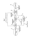
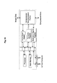
- Figure 6 is a block diagram of the transmitting side of the image transmission system in the first embodiment example of this invention.
- Image data 1 that is inputted through the image input line 2 is stored temporally in the image buffer 3 in Fig. 6.
- the stored image data is sent to the block decider 6, the context generator 5, the template generator 8 and the compression coder 11 through the image data signal line 4, based on the block information provided by the block decider 6.
- the block decider 6 divides inputted image data into blocks by features, so that the following processes can be carried out by each block in order to raise the efficiency in compression coding.
- Image data is inputted into the block decider 6 through the image data signal line 4, the way of image division (the size and the position of each block) is decided by the decider 6 and outputted through the block information signal line 7.
- the way of image division can be otherwise decided or controlled by an external means instead of the block decider 6, by using the block decider control signal that is provided through the block decider control signal line 17.
- the template generator 8 determines the optimum template that can contribute to the maximum compression rate for the inputted image data.
- the image data through the image data signal line 4 and the compressed data through the compressed data signal line 12 are inputted to the template generator 8.
- the compressed data is used as a measure for fitness of the generated template. Compression coding by using an externally determined template is also possible, by forcefully designate the template from an external means through the template generator control signal line 16.
- the context generator 5 generates a pattern of values of reference pixels, or a context, in the image data that is inputted through the image data signal line 4.
- a context is defined as a vector consisting of a string of pixel values, where each position of the pixel is specified by the template.
- a shift register In the template of Fig. 15(a), for example, pixel positions p1, p2 and p3 are set in a line in this order. When this template is shifted to the right by one bit, then the value of position p2 comes to position p1, and the value of position p3 comes to position p2. This means that pixel values that should be newly inputted from the memory are only pixel values for p3 and p4, if a three-bit shift register corresponding to p1 to p3 is used to express a part of template. Consequently, it becomes possible to speed up the processing time since memory address calculation times are reduced.
- the compression coder 11 carries out compression coding of image data that are inputted through image data signal line 4 by using the context inputted through the context signal line 10, in order to generate the compressed data.
- the compression-coded data combiner 13 adds the template that is used to generate said compressed data and the block information that is used as the basis of compression coding to the compressed data, so as to generate the compression-coded data 15.
- the compression-coded data combiner 13 receives the block information through the block information signal line 7, the template through the template signal line 9 and the compressed data through the compressed data signal line 12, respectively. It is also possible to input attribute information concerning the image data (image resolution, the line number used, the screen angle, the name of the system that has generated the data and its version number, the date of generating the image data, etc.) from an outside apparatus to the compression-coded data combiner 13 through the attribute information input line 18, in order to record them in the header portion of the compression-coded data 15.
- the attribute information concerning the image data are inputted from an outside apparatus to the compression-coded data combiner 13 through the attribute information input line 18, and recorded in the header of the compression- coded data, although this attribute information input is not mandatory.
- the image data 1 to be compressed is inputted to the image buffer 3 through the image data input line 2.
- the image data 1 is then transferred to the block decider 6 through the image data signal line 4. Since the size of the image (vertical and horizontal sizes) can be known after this transfer, this size information is sent to the compression-coded data combiner 13 through the block information signal line 7, and then recorded in the header of the compression-coded data 15.
- the way of how to divide the image into blocks is calculated by the block decider 6. It is not necessary to calculate the optimum way of division by the block decider if divided blocks are already determined as is the case of character blocks or photograph blocks in a newspaper space, for example.
- the processing speed can be expedited in this case, by inputting the space configuration information to the block decider 6 through the block decider control information line 17. Otherwise, higher compression efficiency can be expected if more detailed block division is carried out by using the space configuration information as the basis of the division. This method is explained in detail later.
- the block division information determined by the process explained above is sent to the image buffer 3, and the image data is then sent to the template generator 8 by each block.
- the optimum template is calculated for each block according to the process flow chart shown in Fig. 8. This calculation process is explained later. It is not necessary to optimize the template for a character area where characters with a small font are crowded, since it is already known that the template with the configuration where reference pixels are crowded around the noticed pixel, as shown in Fig. 1(a), works effectively in this case. Thus, in such a case where the optimum template is already known as mentioned above, the template is unilaterally determined by the template generator control signal that is conveyed on the template generator control signal line 16.
- the respective context is extracted for each pixel during scanning the block-divided image data that is sent from the image buffer 3 through the image data signal line 4, by using the template that is determined by the template generator 8.
- the compressed data is generated by using each pixel of the block-divided image data that is sent from the image buffer 3 through the image data signal line 4, and by using each context that is obtained through the process explained above.
- the obtained compressed data is sent to the compression-coded data combiner 13 through the compressed data signal line 12, combined with the block information that is sent from the block decider 6 through the block information signal line 7 and with the template that is sent from the template generator 8 through the template signal line 9, and then linked together as compression information for each block so as to be outputted as the compression-coded data 15 to the receiver side through the compression-coded data output line 14.
- the compressed data generated by the compression coder 11 is sent also to the template generator 8 in order to be used in the compression rate calculation that is carried out in the process of template optimization by the template generator 8.
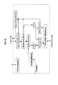
- Figure 7 shows a block diagram of the receiving side of the image transmission system in the first embodiment example of this invention.
- the data analyzer 22 separates the compression information (the block information, the template and the compressed data) of each compressed block and the header portion from the compression-coded data 20 that is inputted through the compression-coded data signal line 21, and then outputs the template and the compressed data according to the block information.
- the context generator 27 recovers the pattern of reference pixel values (the context) in the decoded data that is inputted through the decoded data signal line 29, by using the template that is inputted through the template signal line 25.
- the compression decoder 26 decodes the compressed data inputted through the compressed data signal line 24 to obtain the decoded data, by using the context that is inputted through the context signal line 28.
- the expanded data composer 30 receives the decoded data from the compression decoder 26 via the compression data signal line 29, and configures the inputted decoded data blocks by using the block information that is sent from the data analyzer 21 through the block information signal line 23 in order to compose the expanded data that is to be outputted to an external apparatus through the expanded data output line 28.
- the compression-coded data 20 enters in the data analyzer 22 through the compression-coded data signal line 21.
- the detailed format of the compression-coded data 20 is explained later by using Fig. 24.
- the data analyzer 22 analyzes the compression-coded data 20 and extracts the header portion and the compression information (the block information, the template and the compressed data) separately.
- the attribute information of the original image that is recorded in the header portion is sent to the expanded data composer 30 and used as the header of the expanded data as it is. Since the size of the original image (vertical and horizontal sizes) is always recorded in the header portion also, the expanded data composer can recover the complete original image data as the expanded data, by using this size information.
- the compressed data is sent from data analyzer to the compression decoder 26 through the compressed data signal line 24, while the template corresponding to said compressed data is sent to the context generator 27 through the template signal line 25.
- the compression decoder 26 receives the context from the context generator through the context signal line 28, decodes the compressed data by using this context and then outputs the decoded data through the decoded data signal line 29.
- the decoded data is sent to the context generator 27, where the context is regenerated from the decoded data by using the template.
- the expanded data composer 30 inputs the decoded data from the compression decoder 26 through the decoded data signal line 29, and re-configure the decoded data that is divided into blocks like a patchwork, in order to compose the expanded data as the recovered original image data.
- the expanded data is outputted to an external apparatus through the expanded data output line 28.
- Figure 34 shows an example of realizing the core technology of this invention using hardware.
- the image data compression hardware using the technology of this invention consists of a processor, the main memory, several registers and the compression/decompression portion. Functions of each element in the image data compression hardware in case of image compression are explained in the following.
- the processor decides block division, generates template and interfaces with the host computer.
- the main memory stores the program for block division decision, the program for template generation and the template that is found out.
- Each register is used for interfacing between the processor and the compression/decompression portion.
- the compression/decompression portion generates the context, carries out compression coding and composes the compression-coded data. Composition of the compression-coded data may be carried out by the external computer, otherwise.
- each element in the image data compression hardware in Fig. 7 in case of data decompression is explained in the following.
- the processor is used almost only for data analysis of the data header portion of the compressed data and for interfacing with the host computer, in case of data decompression.
- the main memory stores the data analyzing program that is carried out by the processor.
- Each register works as the interface between the processor and the compression/decompression portion.
- the compression/decompression portion regenerates the context, carries out compression decoding and composes the expanded data. Composition of the expanded data may be carried out by the external computer, otherwise.
- the image data compression hardware using the technology of this invention mentioned above is explained next in the following.
- information such as the size and resolution of the image that is to be compressed and that is stored in the host computer is sent to the processor and the compression/decompression portion in the image data compression hardware.
- the compression/decompression portion records such information data as mentioned above in the header portion of the compression-coded data.
- the processor decides the block division way and optimize the template by using the information data, through cooperation with the compression/decompression portion.
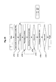
- Figure 8 shows a flowchart of operation procedures for the adaptive template optimization method of this invention realized by software. General flow of the procedures is explained first, and then details for each procedure will be explained.
- the image division step s1 is carried out first for the input image data in preparation for compression coding by each area having a similar feature. Division of the whole image into blocks at one stage and may be one choice and this is considered as two-path processing, while processing where a part of the image is once divided into blocks and the remaining portion of the image is divided into blocks later may be the other choice and this is considered as one-path processing. The latter processing is explained here.
- the template optimization step s2 for each divided block is carried out. After template optimization is finished for all of divided image blocks that are generated by the step s1, division into blocks for remaining image portion and template optimization for each divided block are carried out until the process reaches the ending edge of the image.
- Figure 9 shows the image division process (s1) for block decision.
- image data is inputted recurrently line by line into the image memory of the compression/decompression portion shown in Fig. 35, until the processor detects the ending edge of the block. Detection of the block ending edge is carried out as shown in the following.
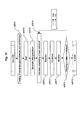
- Figure 10 shows the flow chart of the horizontal division step s12.
- step s121 all of the run lengths that are the numbers of continued pixels with the same color are recorded during the recurrent line by line image scan.
- the feature value of the line under scan is calculated.
- the recorded run lengths are used for division in the vertical direction, and the feature value is used for division in the horizontal direction.
- the average run length or the KL (Kullback-Leibler) information volume based on the simultaneous probability density (probability for every pixel that can be referred to take the same value as the noticed pixel) is used as the feature value.
- the feature value of the presently noticed line and the feature value of the line just before the presently noticed line are compared (s122). If the difference between them exceeds a predetermined value, then a decision is made that lines up to just one line before the noticed line belong to the same block. Detection of the block ending edge is thus carried out. When the line scanning reaches the image ending edge, this edge becomes the block ending edge even the decision threshold is not exceeded.
- Fig. 15(a) Let four pixels, p1 to p4, in Fig. 15(a) be all the pixels that can be referred, and the meshed square in the same figure be the noticed pixel. Also, let the second line in Fig. 15(b) be presently noticed line.
- the probability for each reference pixel to take the same value as the noticed pixel is first calculated by scanning the noticed line, as Fig.15(c) to Fig. 15(e) show. In Fig.15(c), only the pixel p3 has the same value as the noticed pixel. Reference pixels p1 and p4 are considered as not taking the same value as the noticed pixel, since they are out of the defined data area.
- More accurate feature comparison can be possible, if not only the feature value of the line just before the noticed line but also the feature values of all lines from the line of the block starting edge to the line just before the noticed line are calculated, and the average, the moving average or the weighted average of these feature values is used, instead of the simple feature value of the line just before the noticed line, for the comparison with the feature value of the noticed line.
- MDL Minimum Description Length
- AIC Akaike's Information Criterion
- Figure 11 shows the procedure of the division in the vertical direction (s13).
- candidates for vertical division position are selected first. By referring to the run lengths of the same color in each line that have been recorded at the step 121, candidates for vertical division position can be selected for each line.
- Figure 33 shows an example of an image block with the width of 16 pixels and the height of 8 lines.
- eight positions of (a), (c), (d), (f), (i), (I), (n) and (o) are candidate positions for vertical division.
- four positions of (b), (f), (j) and (n) become the candidate positions for vertical division in the second line.
- each of all selected candidate positions is checked whether it is to be used as an actual vertical division position or not.
- a method similar to the decision by majority is used for this purpose. Let a predetermined standard rate be 0.8 as the threshold for selection. Seven lines among eight lines in Fig. 33 have a break of a run at position (b). This means that 7/8, or higher than 0.8, of all lines support the vertical division position of (b), so that (b) is selected as the actual vertical division position for the noticed block. Similarly, (f) and (n) are selected as actual vertical division positions for the block, because all lines have the break of a run at these positions (the rate for selection decision is 1.0).
- the minimum run length is 1 and candidate positions for vertical division are selected as the break of run with the run length larger than 1 in the above example
- the minimum run can be set as a larger value than 2.
- the minimum run length becomes smaller, the number of vertical division becomes larger, since the sensitivity of selecting vertical division positions among candidates becomes higher.
- the minimum run length becomes larger, the number of vertical division becomes smaller, since the sensitivity of selecting vertical division positions among candidates becomes lower.
- vertical division does not occur when the minimum run length is set to a value larger than 2.
- Template optimization for each block (s2) is carried out after the block decision procedure is finished.
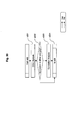
- the calculation procedure of the template optimization is shown in Fig. 28.
- the database is looked up at the step s21 in the figure for an appropriate template.
- the template that is obtained for each block by the seeking that will be explained later is also recorded in the database in the memory 8M shown in Fig. 6.
- the procedure jumps to the step s28 (s26). If no appropriate registered templates can be found at the database looking up, then the procedure goes to the image analysis step s22. At this step, a template that is suitable for the image data is obtained by a statistic process or by a simple equation calculation referring to data features such as periodicity. Then, by using this template obtained by the step s22 as the key for looking up, the database is looked up again (s27). No matter whether the looking up result is that the same template is recorded in the database or not (s27), the procedure goes to the step s28 where decision is made whether the seeking for the optimum template should be carried out or not.
- step s28 decision is made whether the seeking for the optimum template should be carried out or not. The criterion of this decision is explained later. If the decision that the template seeking should not be carried out, then the procedure goes to the step s25 and the template optimization is finished.
- template optimization by using an exploratory method based on Artificial Intelligence is carried out.
- the template obtained by the template seeking is stored in an appropriate area of the database.
- the stored template is used at the database looking up that is already explained, in order to obtain a template with higher accuracy at higher speed.
- the template optimization procedure explained above is carried out for all of divided image blocks that have been generated by the block division procedure that is already explained. It is possible to carry out template optimization only for some of divided image blocks as representatives and to simply apply the obtained templates for other divided blocks in order to expedite processing speed. It is also possible to omit the image analysis and the template seeking, if further expedition in processing is required.
- FIG. 29 shows the processing flow at the step 21 of database looking up.
- the attribute information is collated with the registered contents at the step 211.
- Figure 16 shows an example of the database structure of templates. The name of the system that has generated the image data to be coded, its version number, resolution of the image data, the line number and the screen angle are used as keys for looking up in this example, and a registered template of which attribute exceeds a prescribed threshold is selected as the appropriate template.
- the image analysis result (the input template) in Fig. 16 is the key used for database looking up carried out again at the step 27 in Fig. 28, and is not used at this moment. If a template matched to the divided image block is found at the database looking up of the step s21, then the procedure jumps from the step 26 to the step 28 where a decision is made whether the template seeking should be done or not.
- the criterion of this decision can be (a) whether the compression rate is higher than a predetermined threshold or not, or (b) whether the sum of the correlation amplitude (this term is explained later) of each pixel in the template is larger than the predetermined threshold value or not, as compared to the case where a standard template is used. Although the criterion (a) is used usually, the criterion (b) can be used for expediting the processing speed as much as possible.
- JBIG and JBIG2 standard architectures The default template in JBIG and JBIG2 standard architectures is used as the standard template.
- the template that matched second best at the database looking up step, or the template finally adapted for a block already processed can be also used as the standard template.
- this decision step it is possible to use an image that is cut out from a portion of the noticed block, or to use an image that is thinned out by line or by column from the original block according to a predetermined rule, in order to reduce the time required for calculation.
- template seeking is carried out at the step s23. If a decision is made that template seeking should not be made, then the procedure goes to the step s25 to finish the template optimization. Template seeking will be explained later in detail.
- Figure 30 shows the process flowchart of the image analysis.
- dither analysis is tried first. If dither analysis succeeds, the image analysis process is terminated by this. If it didn't succeed, then correlation analysis is carried out to terminate the image analysis process.
- Dither analysis utilizes the periodicity that arises from the dither matrix used for generating the dither image.
- the procedure of dither analysis is explained in the following. First, correlation amplitude between the noticed pixel and each of all pixels that can be referred is calculated. Next, a pixel that has the strongest amplitude of correlation with the noticed pixel is selected among pixels surrounding the noticed pixel with a distance larger than the predetermined value from the noticed pixel.
- the image to be coded is a dither image that is generated by using dither matrices
- two pixels having strong amplitude of correlation between them are placed at vertices of squares with a specific side length and a specific angle to the scanning line, so that the probability is very high that the distance and the direction from the noticed pixel to a selected pixel satisfy the relationship shown by Fig. 18(a).
- the hatched square is the noticed pixel
- the crossed square is the pixel that has the strongest amplitude of correlation with the noticed pixel among pixels surrounding the noticed pixel with a distance from the noticed pixel larger than the predetermined value
- blank squares are other pixels that are supposed to have strong amplitude of correlation with the noticed pixel from the relationship explained above.
- n the number of reference pixels that configures a template
- n the number of reference pixels that configures a template
- Figure 18(b) shows such an example of the area where the pixels within it can be referred is too small to include enough number of ideally placed pixels.
- the number "n" of reference pixels is 16
- the blank squares without suffixes near the noticed pixel in Fig. 18(b) are selected as reference pixels in order to complement the shortage in number of reference pixels.
- the resultant template cannot work effectively for a natural image, since the adopted reference pixels are gathering to close to each other.
- Dither analysis is finished by finishing processes explained above.
- the dither matrices are known beforehand, calculation of ideal placement of pixels can be omitted, since periodicity and correlation patterns can be clearly obtained from the matrices.
- correlation analysis is carried out at the step s223 in Fig. 30.
- all pixels that compose the divided image blocks are scanned in calculating correlation amplitudes, it is possible to reduce the processing speed by simplifying this calculation. This can be done by scanning only every pixel after several ones, by scanning only every line after several ones, or by scanning only a portion of the image region. For further expediting the calculation, scanning can be limited within a portion of the divided image block.
- step s223 In the correlation analysis of the step s223, all amplitudes of correlation between the noticed pixel and each pixel within the area where the pixel can be referred are calculated. Then, n-pieces of pixels are selected from them in order of stronger correlation, to be used as the initial template when the template consists of n-pieces of pixels. The image analysis process is finished when this selection is finished.
- a selection criterion based simply on the correlation amplitude is used for an image with very strong high frequency components, the selected reference pixels are concentrated in the area around the noticed pixel, as shown in Fig. 1(a). It has been already stated that a template consisting of such reference pixels as these is effective for a character image, but is not effective for a natural image. Thus, it is necessary to scatter widely the position of reference pixels around the noticed pixel, while keeping using a method to select reference pixels simply from ones with strong correlation amplitudes.
- Fig. 17(a) One method to realize this requirement is explained by using Fig. 17(a).
- the hatched square is the noticed pixel
- blank squares are pixels with the correlation amplitude of zero (%)
- squares with a number is pixels with the correlation amplitude of that number (%).
- a template is assumed to consist of three reference pixels. In the case where reference pixels are selected by correlation amplitudes only, those pixels having correlation amplitudes of 100(%), 90(%) and 80(%) compose the template.
- a different template can be generated if the correlation amplitude of a pixel adjacent to the one selected as a reference pixel is forcefully reduced by some amount at each selection.
- the third reference pixel to be selected should be the pixel with the correlation amplitude of 70 (%) in the figure.
- the image analysis result (the input template) is used as the key for the look up (see Fig 16), and a registered template that satisfies the predetermined threshold is outputted.
- template seeking of the step s23 in Fig. 28 is explained.
- template seeking of the step s23 consists of two staged processes.
- a genetic algorithm s231 is executed using the template obtained by the image analysis of the step s21 as the initial template, in order to optimize the template.
- the obtained template is further adjusted by local template seeking of the step s232 in the figure, to finish the step s23.
- a general genetic algorithm assumes that a virtual biological population consisting of individuals having genes exists in a predetermined environment, and that an individual who adapts itself to the given environment better can live longer and can have a higher possibility to have its own descendant.
- the genes of a parental individual are inherited to its child through the process called the genetic operation.
- the genetic operation Through evolution of genes and the biological population by repeating such generation alternation as mentioned above, the number of individuals having higher adaptability to the environment comes to seize the major part of the population.
- Crossover and mutation that occur in actual biological reproduction are also used as genetic operation in the genetic algorithm.
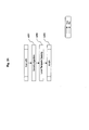
- Figure 12 is a flowchart to show a rough procedure of a genetic algorithm explained above.
- the chromosome of each individual are determined at the step s2311. That is, the contents of data and the way of transferring the contents from the parental individual to the child individual are determined first.
- a i S are determined as a set of integers, real numbers within a given range or a line of simple symbols, according to the nature of the subject.
- alphabets from “a” to “e” are the genes.
- An assembly of symbolized genes as shown in this example composes the chromosome of an individual.
- a calculation method for adaptability that expresses how each individual adapts itself to the environment is determined.
- the method is determined so that as the estimation function value of the variable for the given subject becomes higher (lower), the adaptability of the corresponding individual becomes higher (lower).
- the process is determined so that an individual having higher adaptability can have a higher probability to survive or to make a descendant. Inversely, this process is designed so that an individual having lower adaptability should extinct, deeming that the individual is not adapting itself to the environment properly.
- This method reflects the principle of natural selection in evolutionism. Adaptability is a measure of superiority of an individual in terms of possibility of survival.
- the subject to be encountered is a complete black box at the beginning of seeking, so that what an individual is desirable is totally unknown. It is therefore usual to generate an initial biological population by using random numbers.
- the initial biological population is generated by using random numbers at the step s2313 in Fig. 12, after starting the process at the step s2312. If some knowledge on the seeking space is already acquired, the population may be generated around individuals that are supposed to have high estimation values. Here, the total number of individuals generated is called the individual number of the population.
- step 2314 adaptability of each individual in the biological population is calculated at the step 2314 based on the method decided at the step 2311. Then, at the step 2315, individuals that are to become the base of the next generation are picked up by selection. But selection merely raises the percentage of individuals having the presently highest adaptability among the existing population, without generating any newly sought points. Thus, crossover and mutation that are operations explained in the following are carried out.
- two individuals as a pair are randomly picked up at a predetermined occurrence frequency from the new generation individuals that are generated through selection, and a child chromosome is generated by reforming chromosomes of the picked up pair (crossover).
- the probability that crossover occurs is called the crossover rate.
- the individual generated by crossover inherits the features of the two parental individuals. By the process of crossover, variety in chromosomes of an individual is deepened, and thus evolution occurs.
- a gene of an individual is changed at a predetermined probability at the step s2317 (mutation).
- the probability of mutation occurrence is called the mutation rate. It sometimes happens in actual biological environment that the contents of a gene of an individual are rewritten at a low probability. It should be noted that if the mutation rate is set too high, features of the individual that are inherited from its parents would be lost and the result would be nearly the same as the result of seeking randomly in the seeking space.
- step 2318 whether the newly generated population satisfies the specified evaluation criterion for finishing seeking or not is examined.
- the criterion depends on the subject, but some typical examples may be;
- the seeking is finished when one of above criteria is satisfied, and the individual that has the highest adaptability among the biological population at that time becomes the solution of this optimization subject. If the finishing condition is not satisfied, seeking is continued as the process is returned to the step s2314 of adaptability calculation for each individual.
- Figure 20 shows a method of expressing a gene in the invention.
- the figure shows an example where the number of reference pixels that compose a template is n and the area that can be referred is the region consisting of 256 x 256 pixels.
- n the number of reference pixels that compose a template
- the area that can be referred is the region consisting of 256 x 256 pixels.
- the size can be arbitrarily predetermined.
- a chromosome is divided into n pieces of portions each of which corresponds to one reference pixel. Each portion is further divided into two parts, each of which determines the x coordinate and the y coordinate, respectively. Since the size of the area that can be referred is 256 in both the x direction and the y direction in the example, each of the two parts can be expressed by 8 bit binary numbers.
- the coordinates of a reference pixel can be expressed by using Gray coded numbers, instead of using simple binary numbers. Also, it is possible to express a chromosome by using integers that show the coordinate of a reference pixel, instead of using binary numbers of 1 or 0, or instead of using Gray codes. In Fig. 20(b), for example, both the x-coordinate and the y-coordinate take values of ⁇ 0, ----, 255 ⁇ .
- the initial template is determined for each of divided image block by using an analytic method.
- This initial template is embedded in the population of individuals, in order to compose the population of initial individuals.
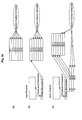
- Figure 26 shows schematic drawings to show examples of how to embed the initial template into the individual population that consists of six chromosomes.
- Figure 26(a) shows a method to initialize all of chromosomes randomly, and is the same as an ordinary genetic algorithm.
- Figure 26(b) shows a method where a master chromosome is generated as the chromosome expression of the initial template, this master chromosome is copied to the first chromosome in the individual population and the rest of five chromosomes are randomly initialized.
- the master chromosome can be copied not only to the first chromosome in the population but also to arbitral number of chromosomes in the individual population.
- Figure 26(c) shows a schematic drawing to show an example of this copying method.
- three chromosomes are mutated from a master chromosome
- the first chromosome of the individual population is copied from the master chromosome
- the second to the fourth chromosomes are copied from three chromosomes that are mutated from the master chromosome, respectively, and only the rest of two chromosomes are randomly initialized.
- the master chromosome can be copied to a plural number of chromosomes in the individual population and the number of chromosomes that are obtained by mutation of the master chromosome can be arbitrarily determined. These variations can be controlled by setting parameters.
- the reciprocal of the size of the compressed data that is obtained by the compression coding of the input image data using the template that the individual determines is used. For example, if the image data is compressed to 1 K bytes, the value of adaptability becomes 1/(1 x 1024).
- the degradation in accuracy of the evaluation function can be reduced by shifting the area to be thinned out or cut out, for each generation.
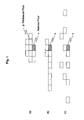
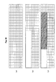
- the cutting out region is shifted by one bit in both vertical and horizontal directions for each generation.
- Most of the (m-1) x (m-1) region that is the major portion of the cut out region of the present generation overlaps the region that is cut out from the region of the parental generation (The hatched portion in Fig. 3). Therefore, the probability is high that the chromosome (the template) evaluated as superior in the parental generation is also evaluated as superior in the child generation.
- the region wider by (2 x m -1) bits is used for the evaluation as compared to the case without shifting the region.
- reduction of accuracy in the evaluation function caused by the cutting out of the region can be prevented, since wider regions can be used for the evaluation by repeating the process mentioned above.
- the shift value is one bit in the above-explained example, a wider area can be used for evaluation if a shift value is set to larger bits, which results in smaller degradation in the accuracy of the evaluation function. Instead, since the area that overlaps the parental generation's area becomes smaller, a lower seeking speed results. For this reason, the shift value should be altered according to the size of the cutting out area.
- the degradation in accuracy of the evaluation function can be further reduced.
- the cutting area is too small as compared to the size of the objective divided image block, it takes much time to shift the cutting out area in order to include the whole block for scan.
- the thinning out method is excellent in that it can maintain the statistic features in the large view, although relationship between adjacent pixels is missed. So that, when both of these two methods are used together, not only the weak points of them are be complemented each other, but also degradation of the evaluation function accuracy can be reduced much, by using a smaller size cutting out region and by expanding the thinning out interval.
- the size of the cutting out region is set to 256 bits x 256 bits and the shifting bit size is set to one bit in the embodiment example of this invention.
- the thinning out spacing is set to (H / 256) in the vertical direction and (W / 256) in the horizontal direction, where H and W denote sizes of the cutting out region in the vertical and horizontal directions, respectively.
- the offset (the position of the first scanning line) is shifted randomly by one bit both in the vertical and the horizontal directions, in order to reduce bias in sampling.
- the entropy can be used as the evaluation function, in stead of the size of the compressed data. Since minimizing the entropy is equivalent to minimizing the size of the compressed data from the stand point of the information theory, they are not distinguished ideally. Cutting out or thinning out that are explained above may be used also in calculating the entropy.
- selection of an individual at the probability that is proportional to its adaptability is repeated by times of the individual number of the population (roulette selection). A new individual population is formed by this step.
- Other selection methods such as tournament selection or ranking selection may be also used.
- Fig. 21(a) the method shown in Fig. 21(a) is applied to two parental individuals A and B that are picked up randomly from the parental population.
- This method is called the one-point crossover that is characterized as a portion of one chromosome starting at a random coordinate position in the chromosome is interchanged as a block with the portion of the other chromosome starting at the same coordinate position.
- Ch1 and Ch2 are the parental chromosomes A and B, respectively, in case of Fig. 21(a).
- the two chromosomes are crossed over at a randomly chosen crossover point shown as CP in the figure, which is the point between the second gene and the third gene.
- a chromosome pair picked up randomly from the population at crossover has the same gene structure, one of the chromosomes of the pair is mutated in order to avoid slowing down of the template seeking speed. Mutation is explained in detail later.
- a chromosome contains a number of blocks having meaningful information with 16bit length as shown in Fig. 20(b). So, by setting the probability of choosing the crossover point from other points than each gap between two adjacent blocks low, the probability that a meaningful information block is broken by crossover is expected to become low, resulting in speed up of template seeking.
- template seeking tends to converge rapidly at the initial stage, since the probability of generating a new information block by crossover becomes small by the above-mentioned process.
- it is effective to set the probability of the crossover point to be selected at a point other than a gap between any two adjacent information blocks to a large value at the early stage of seeking, and to set this probability to a small value as alternation of generations progresses, in order that all of the possible crossover points should be selected at the same probability at last.
- This method can be applied not only to the one-point crossover, but also to other crossover schemes such as the two-point crossover, the multi-point crossover and the uniform crossover.
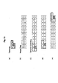
- Fig. 4(a) An example is shown by a template in Fig. 4(a).
- the square marked by the symbol "?” shows the noticed pixel, and the hatched squares mean reference pixels.
- a template expressed by these reference pixels is shown in Fig. 4(b) in the chromosome expression, where each number shows each of information blocks, and crossover points (CP) are limited at a gap position between any two adjacent information blocks.
- the chromosome shown by Fig. 4(c) is another chromosome having the same template (a set of reference pixels) as the one in Fig. 4(b). If these chromosomes are crossed over at the CP of the gap position between second and third information blocks, then two new chromosomes generated by crossover become totally different each other and totally different from their parents, which results in a slower seeking speed.
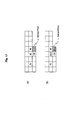
- Figure 5(c) shows the result of the one-point crossover using the CP at the gap position between the second and the third information blocks.
- the two partial chromosomes thus picked up and crossed over are finally returned to the respective original chromosomes, as the result shown in Fig. 5(d).
- the length of the two picked up partial chromosome is null at crossover based on the template expression as is explained above, it means that the original two chromosomes express the same template. In such a case, only one of the two chromosomes will be mutated, in order to avoid slowing down in seeking speed caused by same templates included in one population, as explained previously.
- the mutation is explained in the following.
- Mutation used here after crossover is a process that reverses values of all genes in all chromosomes at a predetermined mutation rate.
- Figure 21(b) shows an example of mutation. In this example, the value of the second gene in the chromosome Ch5 is reversed as the result of mutation at a given mutation rate.
- Mutation can be carried out not bit-wise but information block-wise.
- the value of each information block takes a positive integer number between 0 and 65535, since each information block consists of 16 bits.
- a value of ⁇ (1 + ⁇ ) is added to or subtracted from each information block value at a predetermined mutation rate.
- the effect of mutation becomes weaker and the template seeking speed by the GA (genetic algorithm) is improved.
- a too small ⁇ value results in convergence at an early stage of template seeking, which means failing in obtaining a good template.
- a large ⁇ value can avoid undesired early convergence in template seeking, it reduces seeking speed.
- seeking speed at the later seeking stage can be expedited, avoiding unwanted convergence at the early seeking stage.
- Mutation process explained above can be applied to each of the x-coordinate and the y-coordinate that compose each information block, separately. By doing this, further detailed adjustment of mutation becomes possible.
- This method is to pick up the most superior individual and to pick up another individual randomly from a population, to generate two child individuals by crossover and then mutate one of the child individuals, and to replace the most inferior individual in the initial population with the mutated child individual.
- This method has a feature that it hardly falls into a local optimum solution, since only one individual in each generation is replaced. Seeking speed can be further accelerated, by allowing the replacement only when adaptability of the individual generated by crossover and mutation exceeds adaptability of the most inferior individual in the parental population.
- a so-called blind-seeking method such as the evolution strategy, the hill-climbing method, the annealing method, the taboo seeking or the greedy algorithm can be used instead of using the genetic algorithm.
- the hill climbing method and the annealing method can provide fast processing speed although seeking capability is not such excellent as the genetic algorithm provides.
- Either of the compressed data size and the entropy can be used as an evaluation function for any of above-mentioned blind seeking methods.
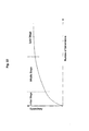
- the genetic algorithm is a very powerful seeking method, it has a problem that seeking speed becomes slower at the last stage of seeking reaching near to the optimum solution or to a local solution.
- the adaptability increasing rate becomes smaller as alternation of generations proceeds from the initial stage to the middle stage, and almost no improvement is made in the last stage.
- the final adjustment is made on the best template that is obtained by the genetic algorithm, by using the hill-climbing method. By introducing this adjustment, the total seeking speed can be expedited, since the time consuming last stage of seeking in the genetic algorithm can be skipped.
- the database is used when experimental knowledge on the image data to be compression coded is already known and the template is decided without carrying out the image analysis step s22 nor the template seeking step s23.
- the image generating procedure based on a dithering method is specifically determined by the manufacturer of the software program, having the manufacturer-specific characteristic in generating a dither matrix, for example.
- a manufacturer-specific characteristic is not opened by the manufacturer for utilization by others in general, by accumulating the results of template seeking into the database as is done in the embodiment of this invention, the accumulated knowledge can be re-used as important clues in deciding the optimum template for a new image.
- the template seeking step s23 in Fig. 28 is carried out by using the information that is registered in the database as an initial value, it is possible sometimes to find a better template.
- Figure 13 is a flow chart to show an operation of the template database renewal step 24 in Fig. 28.
- the template database that has the structure shown in Fig. 16 is looked up to find out whether a template that is generated by the same image generating system and that has the same resolution, scanning line number and the screen angle as those of the noticed template is already registered or not.
- the present template that has been obtained newly by the template seeking is registered in the template database as a new data, and then the step s24 is finished.
- the step s24 is finished.
- this template is the one that is optimized by the template optimization step by using the initial template obtained by the template database looking up or not is examined. If it is, then this template replaces the already registered template at the step s243, since it can be expected that this template is superior to the already registered one in terms of quality.
- superior in quality means that a higher compression rate can be attained by using this template for the predictive coding.
- the optimum template for each divided block can be obtained by processes explained heretofore. Actual compression process for each block is started then.
- the necessary portion of the image data that is divided into a block is cut out and sent to the reference buffer shown in Fig. 35.
- the size of the necessary portion means the height as the line number from the noticed pixel position to the furthest pixel position in the vertical direction and the width as the distance from the noticed pixel position to the furthest pixel position in the horizontal direction.
- the context that is the vector data consisting of reference pixel values, is extracted from the reference buffer based on the template.
- the extracted context and the noticed pixel value are sent to the MQ-Coder (C) via the following FIFO and the compressed data is calculated.
- the MQ-Coder (D) in Fig. 35 is the MQ-coder for decompression.
- the MQ-coder (C) for compression and the MQ-coder (D) for decompression are implemented as separate devices in order to realize high-speed processing easily. Only one MQ-coder that can execute both compression and decompression may be used in order to minimize the gate numbers in the LSI, since it is theoretically possible for the MQ-coder to carry out reversible operation.
- the structure and processing procedures of the MQ-coder are clearly defined by the international standardization body on the JPIG2 algorithm. Also, other entropy coding apparatuses such as the QM-coder or the Johnson coder than the MQ-coder can be used.
- the region that is shifted by one bit is cut out next and sent to the reference buffer, the context is extracted and the calculation of compression at the MQ-coder (C) is carried out. The same procedure is repeated until the end of the image is reached.
- the image region that is shifted by one bit to the right direction from the left edge of the image is cut out to be sent to the reference buffer, and the above-mentioned procedure is repeated until the lower edge of the image block is reached.
- Acceleration in processing speed by using pipe-line processing can be realized as preparing two reference buffers and operating them in parallel alternately.
- the operation is explained by using Fig. 36. It is assumed that the size of the image block is as shown in Fig. 36(a). If the region of reference pixels that is accessible by the noticed pixel is set as 8 pixels x 4 lines in this example, the size required for the following process by the context extractor becomes 8 pixels x 4 lines at the minimum. So that the required size of the reference buffer is 4 lines in height and any pixels more than 8 in width. Here, in the figure, the width is set to 16 pixels.
- the upper left corner of the image block (the blank rectangular in Fig. 36(b)) is written into the first reference buffer. Since the width of this reference buffer is 16 pixels that is twice as large as the size required for extracting the context, the number of contexts that can be extracted is eight by repeating extraction calculation with one bit shifting eight times. During eight times of context extraction calculation, the area that is shifted by eight bits (the hatched rectangular in Fig. 36(c)) is written into the second reference buffer. Just after the first reference buffer finishes providing data of areas necessary for eight times of context extraction calculation, the second reference buffer starts provision of the area data with 8 bit shift without interruption. By alternating above-mentioned processes in turn, the time required for writing the area data into the reference buffers can be almost fully hidden.
- Figure 32 shows a block diagram of the hardware for image data compression that introduced parallel processing as much as possible in order to accelerate operation speed for compression and decompression.
- the configuration of compression/decompression units in the figure are equivalent to the whole configuration of Fig. 35 except that the former does not include either of the image data memory and the control register.
- a DMA processor is used for carrying out fast transmission of image data and compressed data to and from an external host computer by using the DMA (Direct Memory Access) transmission scheme.
- DMA Direct Memory Access
- the features of parallel processing are in that it divides forcefully the image data stored in the image memory into several regions in the vertical direction, and in that it compresses each of them independently in parallel. Since the example of Fig. 32 employs double parallel processing, the time required for compression and decompression is reduced to a half. If n sets of image memories, compression/decompression units and compressed data I/O FIFO are used, then the processing speed can be increased by n times, since the n-multiple processing becomes possible.
- Fig. 32 the two image memories are looked as if they are only one continuous memory by the image input FIFO. The image data is therefore written into these two memories line by line successively.
- Image block division and template optimization for image compression can be carried out for each vertically divided image region independently. Or otherwise, it can be configured as image block division and template optimization for image compression are carried out by the same processes as are used in the first embodiment of the invention, regarding the vertically divided image region as one big block, and only data compression is carried out for each image region in parallel and independently. A higher compression rate can be expected for the former method, while faster processing is realized by the latter method.
- the predictive adaptive coding and decoding methods explained by the first and second embodiment examples of the invention can be realized easily by a computer, by recording programs that execute such predictive adaptive coding and decoding methods explained heretofore into a hard disk, a flexible disk, a CD-ROM, a DVD-ROM or one of all other recording devices, and by reading the programs from the recorded device into the computer.
- the predictive adaptive coding program executes the following processes as the flowchart in Fig. 23 shows;
- the execution method where data for the whole image is inputted once, block division is executed then and compression coding is carried out for each divided block may be used (two-path method), instead of using the execution method where data input and block division are carried out simultaneously as shown in the first embodiment of the invention (one-path method), since it is generally easy to have enough memory capacity than to have enough hardware processing speed.
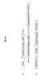
- Figure 24(a) is a modeling figure to show a data formatting example of the compression-coded data in a case where the image data to be compressed is divided into n pieces of blocks.
- One unit of the compression-coded data is consisting of the header portion and n portions of compression information for each image block.
- the header portion the sizes of the image data to be compressed (the vertical size and the horizontal size), image resolution, the line number, the screen angle, the name of the image generating system, its version number and others.
- Figure 24(b) shows a structure example of the compression information unit for the i -th image block, which is consisting of the block header that records the block size and the block position (block information), the template used for compression coding of the corresponding image data, compressed data and the ending mark to show the tail of the i -th compression information unit.
- the decoding program executes the following processes as the flowchart in Fig. 23 shows;
- This invention can be applied to any ordinary two-level images including character images, line images, two-level images coded by the dithering method, the error diffusion method or any of other methods, and any other two-level images including any combinations of them.
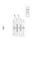
- the invention can be applied to multi-level images also, by converting a multi-level image to a number of two-level images, by using the bit slicing technology or the image width expanding technology. Bit slicing is explained by using Fig. 27(a) as an example, where each pixel of an image is expressed by 8 bits as the small boxes in the figure show.
- Bit slicing is the method to break down one image consisting of these 8 bit pixels (the large box in the figure) to eight images consisting of one bit pixels that are broken out from only the first bits to only the eighth bits of original 8 bit pixels (eight planes in the figure).
- bit slicing an image containing high frequency components is converted to images containing lower frequency components. Since compression of an image containing high frequency component is generally difficult, each of multi-level pixel values can be converted to alternating binary coded numbers (Gray codes) before bit slicing, in order to avoid this difficulty. If the original image consists of a limited number of colors, further efficient bit slicing can be realized by converting the order of the bit row according to correlation between colors.
- Image width expanding is explained by using Fig. 27(b) as an example, where each pixel of an image is expressed by 256 levels (8 bits) as the same as shown in Fig. 27(a).
- Image width expanding is the method to expand the width of the two-level image virtually up to eight times as large, and break down each pixel that composes the eight-level image into a segment of bits placed on the line of the virtually expanded two-level image, as shown in Fig. 27(b).
- the data coding method of this invention can be applied to any arbitral data whereof any correlation exists between bits such as a text file and a data file in any software application systems, although the image data is used as the input data in the embodiment examples of the invention explained heretofore.
- the same template can be used unconditionally within an image information block by dividing the inputted image information into respectively homogeneous blocks. Also, flexible optimization of the template becomes possible by appropriate image division into blocks, making it possible to raise accuracy in estimating pixel values for each divided image block, which results in compression efficiency improvement as a whole.
- a template with higher accuracy can be generated by carrying out statistic processes and analysis assuming the dithering method used for generating the image to be compressed. Furthermore, not only raising the compression efficiency, but also reducing time required for template decision can be attained by the invention, by using a database that stores relationship between the used dithering method and the template generated.
- a template that can contribute to higher prediction accuracy can be obtained by applying an artificial intelligence technology such as the genetic algorithm to adaptively adjust the basic template that is obtained by the above-mentioned method, according to the pattern of the image.
- Speed up of template decision can be also realized at the same time by cutting out a portion of the image without impairing image features in a large view.
Landscapes
- Engineering & Computer Science (AREA)
- Multimedia (AREA)
- Signal Processing (AREA)
- Theoretical Computer Science (AREA)
- Compression Of Band Width Or Redundancy In Fax (AREA)
- Compression, Expansion, Code Conversion, And Decoders (AREA)
- Image Analysis (AREA)
Abstract
A data compression method using a template, in which a template optimizing means using an artificial intelligent technique (such as a genetic algorithm) applied to segments defined by diving input data into uniform segment units contributes to enhancing the prediction accuracy, data is compressed using the results of optimization, and a database is updated to improve the compression efficiency and speed of the subsequent processings. By updating a database by using an optimized template, a template for improving the prediction accuracy is obtained quickly without applying any artificial intelligent technique. <IMAGE>
Description
In relation to a predictive data coding method typically for coding of image
information wherein prediction of the value of a pixel in said image information is
carried out by using the status of pixels that surround said pixel and wherein said
image information is coded by using the result of said prediction, the invention
provides a method to optimize the position pattern of pixels surrounding said pixel
fast and accurately when it is referred, in order to improve efficiency of data
compression.
In a predictive data coding method, data compression efficiency increases
as the accuracy in prediction of each pixel value becomes higher. The prediction
accuracy can be raised by increasing the number of pixels that are referred in the
prediction process. A pixel that is referred in the prediction process will be notified
as "a reference pixel" hereafter. The prediction accuracy can be raised also by
optimizing the position pattern of reference pixels.
Figure 2 shows a position pattern of reference pixels in the JBIG (Joint
Bi-level Image Experts Group) coding architecture. Here, JBIG is the international
standardization body for bi-level image coding where each pixel of an image takes
only a binary value of either "one" or "zero". The position pattern of reference
pixels mentioned above will be referred as a "template" hereafter.
In Fig. 2, the square with hatches shows the noticed pixel, and squares p1
to p9 and the square "A" show reference pixels. Among these 10 reference pixels,
the pixel denoted by A is called an AT (adaptive template) pixel, and this pixel is
allowed to move to any arbitrary position among nearly 256 x 256 pixel positions
depicted in the figure. In most image coding systems using JBIG coding
architecture, however, the AT pixel position is restricted to move to one of the
eight squares with a cross as shown in the figure, since it is very difficult and it
requires much calculation cost to find the most appropriate position for the AT
pixel among vast number of possible positions. In the JBIG recommendation
document, a method that uses surrounding pixels having the strongest correlation
with the noticed pixel is recommended as the AT pixel position determination
method.
In compression coding of images such as characters or figures, using a
template wherein all reference pixels are placed close to the noticed pixel is
generally effective for improving accuracy of prediction (see Kato, et al : An
Adaptive Markov Model Coding Method for Two-level Images using Dynamic
Selection of Reference Pixels, IEICE Transactions, volume J70-B, number 7). For
this reason, the above-mentioned JBIG recommended template works effectively
in predicting the value of the noticed pixel with high accuracy, resulting in a high
data compression rate.
In compression coding of natural images, however, higher prediction
accuracy can be obtained in many cases by placing reference pixels at scattered
positions in a wider area of the image. In this case, how to place reference pixels
in scattered positions depends largely on the nature of the image. In a two-level
image that is coded by using the cluster type dithering, for example, a higher
compression rate cannot be obtained unless the reference pixel position
distribution reflects not only features resulting from the image nature but also the
periodical features resulting from dithering, since pixels with strong correlation
periodically appear in the image when dithering is applied. Since an image
generated by one of other dithering types, such as the vortex type, the Bayer type
or the error scattering type, has also features peculiar to each coding method
used, it is necessary to use a specific template corresponding to the coding
method used, in order to attain higher data compression efficiency.
Unfortunately, however, when a bi-level coded natural image is given, it is
very difficult to know which type of dithering has been used for coding that image.
Furthermore, it is almost impossible to generate an optimum template through
simple calculation, considering features arising from the pattern of the image. This
is the reason why so many architectures to realize high data compression rate in
image coding have been proposed.
For example, in the method proposed by Kato et al. of Utsunomiya
University or in the method proposed in USP 5023611 by Lucent Technologies
Inc., the number of coincidence between the value of the noticed pixel and the
value of a pixel at one of the positions surrounding the noticed pixel is counted for
each pixel in the two-level image, and when the counting results satisfy a specified
condition during the compression procedure, pixels at the surrounding position
having larger coincidence numbers are included in the new template as reference
pixels, in order of coincidence number value.
Besides the method of changing templates successively as mentioned
above, a method to determine a template based on the correlation amplitudes of
surrounding pixels that are obtained before compression for the whole image, and
the method to select a template that is matched to the image information among
previously prepared templates are cited in Kokai No. 6-90363 by Ricoh Company,
Limited.
However, methods to determine a template simply based on the
amplitude of the correlation between surrounding pixels and the noticed pixel
cannot determine the optimum template for a two-level image that is coded by the
cluster type dithering method. This is because a template determined simply by
correlation amplitude usually becomes the one around which reference pixels are
densely crowded as shown in Fig. 1(a) since correlation between pixels within the
same cluster is stronger, despite correlation between plural clusters should be
considered.
On the contrary, in the method proposed in Kokai No. 5-30362 by Fujitsu Ltd.,
distance between the run up to the noticed pixel and the preceding run with the
same color is used as the measure of periodicity. Here, a "run" means a string of
pixels where the same pixel value continues on the same scanning line. This
method, however, cannot work effectively when the image has no periodicity.
In the method proposed in Kokai No. 11-243491 by Mitsubishi Heavy
Industries Ltd., the multiple regression analysis and a genetic algorithm using the
compression rate as the evaluation function are used for the optimization of the
template, considering both the mesh point structure and the features arising from
the image pattern. Genetic algorithms are calculation methods in modeling
biological evolution or adaptation in the nature, and also applied to artificial
intelligence as powerful means of seeking. By using a genetic algorithm, it
becomes possible to find an optimum template among a vast number of possible
candidates.
The proposed method, however, has a problem that the processing speed
is extremely slow. This problem arises from the implementation of a genetic
algorithm. In the calculation process of a genetic algorithm, a population
consisting of a plural number of solution candidates is first prepared, each
candidate is evaluated and then a new population is generated based of the
evaluation results. This first calculation cycle is carried out to obtain the first
generation of the solution, then, recurrent similar calculation cycles are carried out
to obtain each new generation until a specified finishing condition is satisfied.
Consequently, this method requires evaluation time expressed by (the size of the
population) x (the number of the generations).
Meanwhile, in the method proposed in Kokai No. 11-243491, it is
necessary to compress once the whole noticed image and to calculate the
resultant compression rate before finishing one stage of evaluation, since the
method uses the compression rate as the evaluation measure. For this reason,
the calculation time required for optimizing the template in this method becomes
(the size of the population) x (the number of the generations) times larger than the
calculation time without optimizing. For example, if the size of the population is 30
and the generation number is 100, then, the calculation time required for
optimizing the template in this method becomes 3,000 times larger than the
calculation time without optimizing.
If one of above-mentioned genetic algorithms is applied to an image
transmission system such as the facsimile, optimizing the template for
compression by using the genetic algorithm takes even much more time than
required for the transmission of the whole image data without compression.
Likewise, it is by no means practical to use those methods as explained for
compressing an image with a size of several hundred Giga-bytes, an image for
printing, for example, since those methods require a vast amount of time for
calculation.
The purpose of this invention is to solve such problems in predictive
coding as mentioned above, or to provide a method of adaptively adjusting a
template (a position pattern of reference pixels) in order to obtain always high data
compression rate for various kinds of image information.
In order to attain the object of this invention, the process of this invention
is characterized in that (a) the inputted image is divided into several areas based
on the local feature resemblance, (b) the prediction accuracy is increased through
optimization of the template for each divided area by using a database, by
analyzing data and by using an artificial intelligence engine with an accelerator
and (c) the database is renewed by using the result of the optimization in order
that the compression efficiency and the calculation speed can be further increased
in the next recursive process of optimization.
The first characteristic, (a), of the invention method is explained first. To
divide the inputted image information appropriately into several areas means to
divide the image into several areas each of which is homogeneous within it and
heterogeneous to areas outside of it. By dividing the image in this way, it becomes
possible to use the same template within one area unconditionally. Moreover, it
becomes possible to optimize the template flexibly by dividing the image
appropriately, resulting in higher accuracy of predicting pixel values in the divided
image block, and consequently in a higher compression rate for the whole image.
There are two different ways of determining how to divide the image, the
one-path method and the two-path method. In the two-path method, the whole
image is inputted first in order to be analyzed for determining how to divide it, and
then each area is inputted according to the division. This method provides a
precise division way since information for the whole image is utilized, but on the
other hand the processing speed becomes lower, since the method requires data
input twice. In the one-path method, on the contrary, the division way is
determined successively during the image data input. The method cannot always
provide the optimum division since it cannot reflect the features of the whole
image, but it can provide a faster processing speed. This invention is based on the
one-path method, and the image data is inputted along the luster direction. The
inputted data is analyzed line by line in order to appropriately divide the image into
areas. Details of dividing method and actual procedures will be shown later in the
embodiment explanation.
The second characteristic, (b), is explained next. Differently from
conventional methods, a template with higher accuracy is generated in this
invention through statistical processing and through analysis, assuming the
dithering type used for generating the image to be compressed. Additionally, it is
possible not only to increase the efficiency of the compression in coding, but also
to reduce drastically the time required for determining the template, by using a
database in which relationship between the assumed dithering type and the
template is stored. Furthermore, by adaptively matching the template obtained
through the above-mentioned process to the image pattern utilizing an artificial
intelligence engine such as a genetic algorithm, a renewed template that can be
used for further increasing the accuracy of prediction can be obtained. Also,
speed up in template generation is realized at the same time, by extracting a
portion of the image without damaging image features in the large view.
Finally, the third characteristic, (c), is explained. By feeding back the new
template obtained in the process that is explained above for characteristic (b) to
renew the database, an image data compression system that become wiser as it
is used more can be established. In other words, by recurrently processing image
data blocks with the same or similar features, it becomes possible to obtain rapidly
a template that can contribute to increasing prediction accuracy, even without
using a sophisticated artificial intelligence technology. This scheme may be
considered as one of autonomous self-learning expert systems.
The preferred embodiment of the invention is explained in detail in the
following, referring to figures.
Figure 6 is a block diagram of the transmitting side of the image
transmission system in the first embodiment example of this invention. Image data
1 that is inputted through the image input line 2 is stored temporally in the image
buffer 3 in Fig. 6. The stored image data is sent to the block decider 6, the context
generator 5, the template generator 8 and the compression coder 11 through the
image data signal line 4, based on the block information provided by the block
decider 6.
The block decider 6 divides inputted image data into blocks by features,
so that the following processes can be carried out by each block in order to raise
the efficiency in compression coding. Image data is inputted into the block decider
6 through the image data signal line 4, the way of image division (the size and the
position of each block) is decided by the decider 6 and outputted through the
block information signal line 7. The way of image division can be otherwise
decided or controlled by an external means instead of the block decider 6, by
using the block decider control signal that is provided through the block decider
control signal line 17.
The template generator 8 determines the optimum template that can
contribute to the maximum compression rate for the inputted image data. The
image data through the image data signal line 4 and the compressed data through
the compressed data signal line 12 are inputted to the template generator 8. The
compressed data is used as a measure for fitness of the generated template.
Compression coding by using an externally determined template is also possible,
by forcefully designate the template from an external means through the template
generator control signal line 16.
The context generator 5 generates a pattern of values of reference pixels,
or a context, in the image data that is inputted through the image data signal line
4.
A context is defined as a vector consisting of a string of pixel values,
where each position of the pixel is specified by the template. For the template in
Fig. 15 (a) where the meshed square is the noticed pixel position and p1 to p4 are
reference pixel positions, respectively, each pixel value for pixel position p1 to p4
in Fig. (d), for example, is shown as p1=0, p2=1, p3=1 and p4=1, respectively. So
that, the vector consisting of a string of these values, <0111>, becomes the
context in this case.
It is possible to expedite processing speed of the context generator by
using a shift register. In the template of Fig. 15(a), for example, pixel positions p1,
p2 and p3 are set in a line in this order. When this template is shifted to the right
by one bit, then the value of position p2 comes to position p1, and the value of
position p3 comes to position p2. This means that pixel values that should be
newly inputted from the memory are only pixel values for p3 and p4, if a three-bit
shift register corresponding to p1 to p3 is used to express a part of template.
Consequently, it becomes possible to speed up the processing time since memory
address calculation times are reduced.
The compression coder 11 carries out compression coding of image data
that are inputted through image data signal line 4 by using the context inputted
through the context signal line 10, in order to generate the compressed data.
The compression-coded data combiner 13 adds the template that is used
to generate said compressed data and the block information that is used as the
basis of compression coding to the compressed data, so as to generate the
compression-coded data 15. For this purpose, the compression-coded data
combiner 13 receives the block information through the block information signal
line 7, the template through the template signal line 9 and the compressed data
through the compressed data signal line 12, respectively. It is also possible to
input attribute information concerning the image data (image resolution, the line
number used, the screen angle, the name of the system that has generated the
data and its version number, the date of generating the image data, etc.) from an
outside apparatus to the compression-coded data combiner 13 through the
attribute information input line 18, in order to record them in the header portion of
the compression-coded data 15.
Processes beginning by image data compression and finishing by output
of the compression-coded data 15 are simply explained in the following, referring
to Fig. 6.
First, the attribute information concerning the image data are inputted
from an outside apparatus to the compression-coded data combiner 13 through
the attribute information input line 18, and recorded in the header of the
compression- coded data, although this attribute information input is not
mandatory.
Next, the image data 1 to be compressed is inputted to the image buffer 3
through the image data input line 2. The image data 1 is then transferred to the
block decider 6 through the image data signal line 4. Since the size of the image
(vertical and horizontal sizes) can be known after this transfer, this size
information is sent to the compression-coded data combiner 13 through the block
information signal line 7, and then recorded in the header of the
compression-coded data 15.
The way of how to divide the image into blocks is calculated by the block
decider 6. It is not necessary to calculate the optimum way of division by the block
decider if divided blocks are already determined as is the case of character blocks
or photograph blocks in a newspaper space, for example. The processing speed
can be expedited in this case, by inputting the space configuration information to
the block decider 6 through the block decider control information line 17.
Otherwise, higher compression efficiency can be expected if more detailed block
division is carried out by using the space configuration information as the basis of
the division. This method is explained in detail later.
The block division information determined by the process explained above
is sent to the image buffer 3, and the image data is then sent to the template
generator 8 by each block. In the template generator 8, the optimum template is
calculated for each block according to the process flow chart shown in Fig. 8. This
calculation process is explained later. It is not necessary to optimize the template
for a character area where characters with a small font are crowded, since it is
already known that the template with the configuration where reference pixels are
crowded around the noticed pixel, as shown in Fig. 1(a), works effectively in this
case. Thus, in such a case where the optimum template is already known as
mentioned above, the template is unilaterally determined by the template
generator control signal that is conveyed on the template generator control signal
line 16.
In the context generator 5, the respective context is extracted for each
pixel during scanning the block-divided image data that is sent from the image
buffer 3 through the image data signal line 4, by using the template that is
determined by the template generator 8.
In the compression coder 11, the compressed data is generated by using
each pixel of the block-divided image data that is sent from the image buffer 3
through the image data signal line 4, and by using each context that is obtained
through the process explained above.
The obtained compressed data is sent to the compression-coded data
combiner 13 through the compressed data signal line 12, combined with the block
information that is sent from the block decider 6 through the block information
signal line 7 and with the template that is sent from the template generator 8
through the template signal line 9, and then linked together as compression
information for each block so as to be outputted as the compression-coded data
15 to the receiver side through the compression-coded data output line 14.
The compressed data generated by the compression coder 11 is sent also
to the template generator 8 in order to be used in the compression rate calculation
that is carried out in the process of template optimization by the template
generator 8.
Figure 7 shows a block diagram of the receiving side of the image
transmission system in the first embodiment example of this invention. The data
analyzer 22 separates the compression information (the block information, the
template and the compressed data) of each compressed block and the header
portion from the compression-coded data 20 that is inputted through the
compression-coded data signal line 21, and then outputs the template and the
compressed data according to the block information.
The context generator 27 recovers the pattern of reference pixel values
(the context) in the decoded data that is inputted through the decoded data signal
line 29, by using the template that is inputted through the template signal line 25.
The compression decoder 26 decodes the compressed data inputted
through the compressed data signal line 24 to obtain the decoded data, by using
the context that is inputted through the context signal line 28.
Since the compression decoder 26 outputs the decoded data that is
divided into blocks piecewise like a patchwork, it is necessary to re-configure
these blocks in correct order so as to recover the original image. For this purpose,
the expanded data composer 30 receives the decoded data from the compression
decoder 26 via the compression data signal line 29, and configures the inputted
decoded data blocks by using the block information that is sent from the data
analyzer 21 through the block information signal line 23 in order to compose the
expanded data that is to be outputted to an external apparatus through the
expanded data output line 28.
Processes beginning by compression-coded data input and ending by
output of the expanded data are shortly explained in the following, referring to Fig.
7.
First, the compression-coded data 20 enters in the data analyzer 22
through the compression-coded data signal line 21. The detailed format of the
compression-coded data 20 is explained later by using Fig. 24. The data analyzer
22 analyzes the compression-coded data 20 and extracts the header portion and
the compression information (the block information, the template and the
compressed data) separately.
The attribute information of the original image that is recorded in the
header portion is sent to the expanded data composer 30 and used as the header
of the expanded data as it is. Since the size of the original image (vertical and
horizontal sizes) is always recorded in the header portion also, the expanded data
composer can recover the complete original image data as the expanded data, by
using this size information.
The compressed data is sent from data analyzer to the compression
decoder 26 through the compressed data signal line 24, while the template
corresponding to said compressed data is sent to the context generator 27
through the template signal line 25. The compression decoder 26 receives the
context from the context generator through the context signal line 28, decodes the
compressed data by using this context and then outputs the decoded data through
the decoded data signal line 29. The decoded data is sent to the context
generator 27, where the context is regenerated from the decoded data by using
the template.
The expanded data composer 30 inputs the decoded data from the
compression decoder 26 through the decoded data signal line 29, and
re-configure the decoded data that is divided into blocks like a patchwork, in order
to compose the expanded data as the recovered original image data. The
expanded data is outputted to an external apparatus through the expanded data
output line 28.
Figure 34 shows an example of realizing the core technology of this
invention using hardware. The image data compression hardware using the
technology of this invention consists of a processor, the main memory, several
registers and the compression/decompression portion. Functions of each element
in the image data compression hardware in case of image compression are
explained in the following. The processor decides block division, generates
template and interfaces with the host computer. The main memory stores the
program for block division decision, the program for template generation and the
template that is found out. Each register is used for interfacing between the
processor and the compression/decompression portion. The
compression/decompression portion generates the context, carries out
compression coding and composes the compression-coded data. Composition of
the compression-coded data may be carried out by the external computer,
otherwise.
Functions of each element in the image data compression hardware in Fig.
7 in case of data decompression is explained in the following. The processor is
used almost only for data analysis of the data header portion of the compressed
data and for interfacing with the host computer, in case of data decompression. As
is similar to the data compression case, the main memory stores the data
analyzing program that is carried out by the processor. Each register works as the
interface between the processor and the compression/decompression portion.
The compression/decompression portion regenerates the context, carries out
compression decoding and composes the expanded data. Composition of the
expanded data may be carried out by the external computer, otherwise.
Operation of the image data compression hardware using the technology
of this invention mentioned above is explained next in the following. Firstly at
beginning compression, information such as the size and resolution of the image
that is to be compressed and that is stored in the host computer is sent to the
processor and the compression/decompression portion in the image data
compression hardware. The compression/decompression portion records such
information data as mentioned above in the header portion of the
compression-coded data. The processor decides the block division way and
optimize the template by using the information data, through cooperation with the
compression/decompression portion.
Figure 8 shows a flowchart of operation procedures for the adaptive
template optimization method of this invention realized by software. General flow
of the procedures is explained first, and then details for each procedure will be
explained.
The image division step s1 is carried out first for the input image data in
preparation for compression coding by each area having a similar feature. Division
of the whole image into blocks at one stage and may be one choice and this is
considered as two-path processing, while processing where a part of the image is
once divided into blocks and the remaining portion of the image is divided into
blocks later may be the other choice and this is considered as one-path
processing. The latter processing is explained here.
Once a portion of the image is divided into a plural number of blocks, then
the template optimization step s2 for each divided block is carried out. After
template optimization is finished for all of divided image blocks that are generated
by the step s1, division into blocks for remaining image portion and template
optimization for each divided block are carried out until the process reaches the
ending edge of the image.
Figure 9 shows the image division process (s1) for block decision. In the
horizontal division step s12, image data is inputted recurrently line by line into the
image memory of the compression/decompression portion shown in Fig. 35, until
the processor detects the ending edge of the block. Detection of the block ending
edge is carried out as shown in the following.
Figure 10 shows the flow chart of the horizontal division step s12. In the
step s121, all of the run lengths that are the numbers of continued pixels with the
same color are recorded during the recurrent line by line image scan. At the same
time, the feature value of the line under scan is calculated. The recorded run
lengths are used for division in the vertical direction, and the feature value is used
for division in the horizontal direction. The average run length or the KL
(Kullback-Leibler) information volume based on the simultaneous probability
density (probability for every pixel that can be referred to take the same value as
the noticed pixel) is used as the feature value.
Next, the feature value of the presently noticed line and the feature value
of the line just before the presently noticed line are compared (s122). If the
difference between them exceeds a predetermined value, then a decision is made
that lines up to just one line before the noticed line belong to the same block.
Detection of the block ending edge is thus carried out. When the line scanning
reaches the image ending edge, this edge becomes the block ending edge even
the decision threshold is not exceeded.
Here, the simultaneous probability density is explained in detail by using
Fig. 15. Let four pixels, p1 to p4, in Fig. 15(a) be all the pixels that can be referred,
and the meshed square in the same figure be the noticed pixel. Also, let the
second line in Fig. 15(b) be presently noticed line. In order to obtain the
simultaneous probability density, the probability for each reference pixel to take
the same value as the noticed pixel is first calculated by scanning the noticed line,
as Fig.15(c) to Fig. 15(e) show. In Fig.15(c), only the pixel p3 has the same value
as the noticed pixel. Reference pixels p1 and p4 are considered as not taking the
same value as the noticed pixel, since they are out of the defined data area. In the
similar way, p2, p3 and p4 in Fig. 15(d), and p1, p2 and p3 in Fig. 15(e) have the
same value as the noticed pixel. Consequently, after scanning is made for the
noticed line from Fig. 15(c) to Fig.15(e), each number of times for each of
reference pixels, p1 to p4, to take the same value as the noticed pixel becomes 7,
7, 7, and 6, respectively. These values are divided by the total number of times,
27, for normalization in order to obtain the simultaneous probability density for
each reference pixel, which results in 7/27, 7/27, 7/27 and 6/27, respectively.
Calculation procedure of the KL information volume based on the
simultaneous probability density is explained in the following. Let xi and yi be the
information volume of the noticed line and the information volume of the line just
before the noticed line, respectively, then the KL information volume, KLD, is
expressed as;
KLD = KL(x) + KL(y),
here,
KL(x) = Σ {Xi x log(Xi /Yi )},
and
KL(y) = Σ {Yi x log(Yi /Xi )}.
More accurate feature comparison can be possible, if not only the feature
value of the line just before the noticed line but also the feature values of all lines
from the line of the block starting edge to the line just before the noticed line are
calculated, and the average, the moving average or the weighted average of these
feature values is used, instead of the simple feature value of the line just before
the noticed line, for the comparison with the feature value of the noticed line.
As the measure of feature comparison, the Minimum Description Length
(MDL) standard, the Akaike's Information Criterion (AIC) or the distance between
vectors can be used instead of the KL information volume.
In order to expedite calculation speed, it is possible to calculate feature
values only for reference pixels in the template that is used for the block just
before the present block, instead of calculating feature values for all pixels that
can be referred.
After the block border in the horizontal direction is detected, the block can
be further divided in the vertical direction. Figure 11 shows the procedure of the
division in the vertical direction (s13).
At the step s131, candidates for vertical division position are selected first.
By referring to the run lengths of the same color in each line that have been
recorded at the step 121, candidates for vertical division position can be selected
for each line.
Figure 33 shows an example of an image block with the width of 16 pixels
and the height of 8 lines. In the top line, eight positions of (a), (c), (d), (f), (i), (I), (n)
and (o) are candidate positions for vertical division. Similarly, four positions of (b),
(f), (j) and (n) become the candidate positions for vertical division in the second
line. By repeating similar procedure for all other lines, candidate positions for
vertical division can be selected for each of all lines.
Next, in the step s132, each of all selected candidate positions is checked
whether it is to be used as an actual vertical division position or not. A method
similar to the decision by majority is used for this purpose. Let a predetermined
standard rate be 0.8 as the threshold for selection. Seven lines among eight lines
in Fig. 33 have a break of a run at position (b). This means that 7/8, or higher than
0.8, of all lines support the vertical division position of (b), so that (b) is selected as
the actual vertical division position for the noticed block. Similarly, (f) and (n) are
selected as actual vertical division positions for the block, because all lines have
the break of a run at these positions (the rate for selection decision is 1.0).
Although the minimum run length is 1 and candidate positions for vertical
division are selected as the break of run with the run length larger than 1 in the
above example, the minimum run can be set as a larger value than 2. As the
minimum run length becomes smaller, the number of vertical division becomes
larger, since the sensitivity of selecting vertical division positions among
candidates becomes higher. Inversely, as the minimum run length becomes larger,
the number of vertical division becomes smaller, since the sensitivity of selecting
vertical division positions among candidates becomes lower. Actually in the above
example, vertical division does not occur when the minimum run length is set to a
value larger than 2.
It is possible to install a dedicated calculation unit in the
compression/decompression portion in Fig. 34 and to carry out block decision
through horizontal and vertical block division by this unit, instead of doing this
calculation by the processor in Fig. 34.
Template optimization for each block (s2) is carried out after the block
decision procedure is finished. The calculation procedure of the template
optimization is shown in Fig. 28.
First, the database is looked up at the step s21 in the figure for an
appropriate template. In addition to the templates that have been registered in
advance for each block, the template that is obtained for each block by the
seeking that will be explained later is also recorded in the database in the memory
8M shown in Fig. 6.
If a pre-registered template for the block is found as appropriate at the
database looking up, the procedure jumps to the step s28 (s26). If no appropriate
registered templates can be found at the database looking up, then the procedure
goes to the image analysis step s22. At this step, a template that is suitable for the
image data is obtained by a statistic process or by a simple equation calculation
referring to data features such as periodicity. Then, by using this template
obtained by the step s22 as the key for looking up, the database is looked up
again (s27). No matter whether the looking up result is that the same template is
recorded in the database or not (s27), the procedure goes to the step s28 where
decision is made whether the seeking for the optimum template should be carried
out or not.
At the step s28, decision is made whether the seeking for the optimum
template should be carried out or not. The criterion of this decision is explained
later. If the decision that the template seeking should not be carried out, then the
procedure goes to the step s25 and the template optimization is finished.
At the step s23, template optimization by using an exploratory method
based on Artificial Intelligence is carried out. Finally, the template obtained by the
template seeking is stored in an appropriate area of the database. The stored
template is used at the database looking up that is already explained, in order to
obtain a template with higher accuracy at higher speed.
The template optimization procedure explained above is carried out for all
of divided image blocks that have been generated by the block division procedure
that is already explained. It is possible to carry out template optimization only for
some of divided image blocks as representatives and to simply apply the obtained
templates for other divided blocks in order to expedite processing speed. It is also
possible to omit the image analysis and the template seeking, if further expedition
in processing is required.
Each processing step in Fig. 28 is explained in detail in the following.
Figure 29 shows the processing flow at the step 21 of database looking up. The
attribute information is collated with the registered contents at the step 211.
Figure 16 shows an example of the database structure of templates. The name of
the system that has generated the image data to be coded, its version number,
resolution of the image data, the line number and the screen angle are used as
keys for looking up in this example, and a registered template of which attribute
exceeds a prescribed threshold is selected as the appropriate template.
The image analysis result (the input template) in Fig. 16 is the key used
for database looking up carried out again at the step 27 in Fig. 28, and is not used
at this moment. If a template matched to the divided image block is found at the
database looking up of the step s21, then the procedure jumps from the step 26 to
the step 28 where a decision is made whether the template seeking should be
done or not. The criterion of this decision can be (a) whether the compression rate
is higher than a predetermined threshold or not, or (b) whether the sum of the
correlation amplitude (this term is explained later) of each pixel in the template is
larger than the predetermined threshold value or not, as compared to the case
where a standard template is used. Although the criterion (a) is used usually, the
criterion (b) can be used for expediting the processing speed as much as possible.
The default template in JBIG and JBIG2 standard architectures is used as
the standard template. The template that matched second best at the database
looking up step, or the template finally adapted for a block already processed can
be also used as the standard template.
At this decision step, it is possible to use an image that is cut out from a
portion of the noticed block, or to use an image that is thinned out by line or by
column from the original block according to a predetermined rule, in order to
reduce the time required for calculation.
It is possible for an external system or an operator to decide forcefully
whether the template seeking should be carried out or not.
If a decision is made that template seeking should be made, then
template seeking is carried out at the step s23. If a decision is made that template
seeking should not be made, then the procedure goes to the step s25 to finish the
template optimization. Template seeking will be explained later in detail.
If no templates that satisfy the criteria are found, then the procedure goes
to image analysis of the step 22 from the step 26.
Figure 30 shows the process flowchart of the image analysis. In the flow,
dither analysis is tried first. If dither analysis succeeds, the image analysis process
is terminated by this. If it didn't succeed, then correlation analysis is carried out to
terminate the image analysis process.
Dither analysis utilizes the periodicity that arises from the dither matrix
used for generating the dither image. The procedure of dither analysis is explained
in the following. First, correlation amplitude between the noticed pixel and each of
all pixels that can be referred is calculated. Next, a pixel that has the strongest
amplitude of correlation with the noticed pixel is selected among pixels
surrounding the noticed pixel with a distance larger than the predetermined value
from the noticed pixel.
When the image to be coded is a dither image that is generated by using
dither matrices, two pixels having strong amplitude of correlation between them
are placed at vertices of squares with a specific side length and a specific angle to
the scanning line, so that the probability is very high that the distance and the
direction from the noticed pixel to a selected pixel satisfy the relationship shown
by Fig. 18(a). In the figure, the hatched square is the noticed pixel, the crossed
square is the pixel that has the strongest amplitude of correlation with the noticed
pixel among pixels surrounding the noticed pixel with a distance from the noticed
pixel larger than the predetermined value and blank squares are other pixels that
are supposed to have strong amplitude of correlation with the noticed pixel from
the relationship explained above. These pixels that have strong amplitude of
correlation with the noticed pixel will be called "ideally placed pixels" hereafter. By
selecting reference pixels out of these ideally placed pixels, more accurate
template decision can be realized than using a reference pixel selection method
based simply on correlation amplitudes of the pixels.
If "m", the number of ideally placed pixels existing in the area where the
pixels within it can be referred, is larger than "n", the number of reference pixels
that configures a template, then n-pieces are selected out of m-pieces of ideally
placed pixels in order of smaller distance from the noticed pixel, so as to be
utilized as the reference pixels that compose the initial template. For example, if
the ideally placed pixels are configured as shown in Fig. 18(a) and n = 10, then
ideally placed pixels shown as p1 to p10 are selected as reference pixels.
Inversely, if "m", the number of ideally placed pixels existing in the area
where the pixels within it can be referred, is smaller than "n", the number of
reference pixels that configures a template, then reference pixels are selected
from pixels adjacent to the noticed pixel and from pixels adjacent to the ideally
placed pixels, in order of smaller distance from the noticed pixel. For example, if
the ideally placed pixels are configured as shown in Fig. 18(a) and n = 16, then
ideally placed pixels shown as p1 to p13 are selected as reference pixels.
Additionally, three more reference pixels are selected as reference pixels in order
of stronger correlation amplitude with the noticed pixel, so that they complement
the shortage in number.
When the area where the pixels within it can be referred to is too small to
include enough number of ideally placed pixels, or when distances between each
of ideally placed pixels are much larger than the scale of the area where the pixels
within it can be referred, it is likely that reference pixels other than ideally placed
pixels are all selected from the neighbor of the noticed pixels, since pixels that
have larger amplitude of correlation with the noticed pixel generally exist near the
noticed pixel.
Figure 18(b) shows such an example of the area where the pixels within it
can be referred is too small to include enough number of ideally placed pixels. In a
case where the number "n" of reference pixels is 16, it is very likely that nine
reference pixels other than the ideally placed pixels p1 to p7 are selected from the
area close to the noticed pixel. There is a high possibility that the blank squares
without suffixes near the noticed pixel in Fig. 18(b) are selected as reference
pixels in order to complement the shortage in number of reference pixels.
However, the resultant template cannot work effectively for a natural image, since
the adopted reference pixels are gathering to close to each other.
In order to avoid such a situation as mentioned above, the template is
determined through the process explained in the following. First, among pixels
adjacent to the noticed pixel, the one having the largest amplitude of correlation
with the noticed pixel is selected as a reference pixel. Next, ideally placed pixels
are selected as reference pixels in order of larger amplitude of correlation with the
noticed pixel. Then, pixels are selected among ones adjacent to each of the
selected ideally placed pixels in order of larger amplitude of correlation with the
noticed pixel. In the example of Fig. 18(b), fifteen ( = 1 + 7 x 2) reference pixels,
that is, one pixel adjacent to the noticed pixel, seven ideally placed pixels and
seven pixels adjacent to each of seven ideally placed pixels, are determined by
the process up to this point. If number of selected reference point is still less than
required for composing the template, then another reference pixel is selected from
pixels adjacent to the noticed pixel, and further pixels next to each of ideally
placed pixels are selected. The similar process as mentioned above is repeated
until the total number of selected reference pixels reaches to the required value
for composing the template.
In the dither analysis explained above, it is possible to reduce calculation
time drastically by using simultaneous probability densities that have been already
calculated at the image division process, instead of using correlation amplitudes.
Dither analysis is finished by finishing processes explained above. In a
case where the dither matrices are known beforehand, calculation of ideal
placement of pixels can be omitted, since periodicity and correlation patterns can
be clearly obtained from the matrices.
If dither analysis cannot work effectively, correlation analysis is carried out
at the step s223 in Fig. 30. Although usually all pixels that compose the divided
image blocks are scanned in calculating correlation amplitudes, it is possible to
reduce the processing speed by simplifying this calculation. This can be done by
scanning only every pixel after several ones, by scanning only every line after
several ones, or by scanning only a portion of the image region. For further
expediting the calculation, scanning can be limited within a portion of the divided
image block.
In the correlation analysis of the step s223, all amplitudes of correlation
between the noticed pixel and each pixel within the area where the pixel can be
referred are calculated. Then, n-pieces of pixels are selected from them in order of
stronger correlation, to be used as the initial template when the template consists
of n-pieces of pixels. The image analysis process is finished when this selection is
finished.
If a selection criterion based simply on the correlation amplitude is used
for an image with very strong high frequency components, the selected reference
pixels are concentrated in the area around the noticed pixel, as shown in Fig. 1(a).
It has been already stated that a template consisting of such reference pixels as
these is effective for a character image, but is not effective for a natural image.
Thus, it is necessary to scatter widely the position of reference pixels around the
noticed pixel, while keeping using a method to select reference pixels simply from
ones with strong correlation amplitudes.
One method to realize this requirement is explained by using Fig. 17(a). In
the figure, the hatched square is the noticed pixel, blank squares are pixels with
the correlation amplitude of zero (%) and squares with a number is pixels with the
correlation amplitude of that number (%). In the example of Fig. 17(a), a template
is assumed to consist of three reference pixels. In the case where reference pixels
are selected by correlation amplitudes only, those pixels having correlation
amplitudes of 100(%), 90(%) and 80(%) compose the template. A different
template, however, can be generated if the correlation amplitude of a pixel
adjacent to the one selected as a reference pixel is forcefully reduced by some
amount at each selection.
For example, if the correlation amplitude of a pixel adjacent to the one
selected as a reference pixel is forcefully reduced to 90% of its original value at
each selection, then the status becomes as shown in Fig. 17(b) after two pixels
with correlation amplitudes of 100(%) and 90(%) are selected. That is, the
correlation amplitude of the pixel with its original correlation amplitude of 80(%) is
reduced to as low value as 80 x 0.9 x 0.9 = 64.8 (%), after the selection of the two
reference pixels. Thus the third reference pixel to be selected should be the pixel
with the correlation amplitude of 70 (%) in the figure.
In the correlation analysis explained above, it is possible to reduce
calculation time drastically by using simultaneous probability densities that have
been already calculated at the image division process, instead of using correlation
amplitudes.
The fact that a template that matches to the image analysis result (input
template) as the looking up key has been already registered in the database
means that the compression process has been carried out before for image data
that has very similar statistic features to those of the image data that is currently
going to be compressed. In other words, by using the registered template that was
obtained by the past template seeking, it becomes possible to use the more
effective template than the one obtained simply as the image analysis result for
the present image data, without wasting time for seeking a new template.
Although the probability that the template that was effective for an image
is also effective for another image that have very similar image features is high, it
cannot be always assured. For example, in a dither image processed by the error
diffusion method, reference pixels decided by the statistic method tend to crowd
around the noticed pixel as shown in Fig. 1(a) regardless of picture patterns. So
that, in case such situation mentioned above is expected to occur, the situation
can be avoided by setting beforehand the threshold for the matching decision in
the database looking up process at a higher value. Or otherwise, if the threshold is
set to a different value corresponding to each of different dither methods, the
above-mentioned issue can be solved automatically.
Explanation for the image analysis of the step s22 in Fig. 28 finishes here,
and database re-looking up of the step s27 in the figure will be explained next.
Differently from the database looking up of the step s21, only the image
analysis result (the input template) is used as the key for the look up (see Fig 16),
and a registered template that satisfies the predetermined threshold is outputted.
After the database re-looking up is finished, a decision whether the
template seeking should be carried out or not is made at the step 28, which
procedure has been explained heretofore.
Next, template seeking of the step s23 in Fig. 28 is explained. As the
flowchart in Fig. 31 shows, template seeking of the step s23 consists of two
staged processes. At the first stage, a genetic algorithm s231 is executed using
the template obtained by the image analysis of the step s21 as the initial template,
in order to optimize the template. Then, at the second stage, the obtained
template is further adjusted by local template seeking of the step s232 in the
figure, to finish the step s23.
First, the genetic algorithm, s231 in Fig. 31, is explained. There are some
published reference documents for genetic algorithms. An example may be
"Genetic Algorithms in Search, Optimization and Machine Learning" by David E.
Goldberg, ADDISON-WESLEY PUBLISHING, 1989.
A general genetic algorithm assumes that a virtual biological population
consisting of individuals having genes exists in a predetermined environment, and
that an individual who adapts itself to the given environment better can live longer
and can have a higher possibility to have its own descendant. The genes of a
parental individual are inherited to its child through the process called the genetic
operation. Through evolution of genes and the biological population by repeating
such generation alternation as mentioned above, the number of individuals having
higher adaptability to the environment comes to seize the major part of the
population. Crossover and mutation that occur in actual biological reproduction are
also used as genetic operation in the genetic algorithm.
Figure 12 is a flowchart to show a rough procedure of a genetic algorithm
explained above. First, the chromosome of each individual are determined at the
step s2311. That is, the contents of data and the way of transferring the contents
from the parental individual to the child individual are determined first. Figure 19
shows an example of a chromosome. Let a vector "x" of variables in the present
optimization subject be expressed by a column consisting of M-pieces of symbols,
Ai (i = 1, 2, - - - -, M), and consider the vector as a chromosome consisting of M
pieces of genes. In the example of Fig. 19, "Ch" shows a chromosome and "Gs"
shows a gene, and the number of genes, M, is 5 here. Values of genes, AiS, are
determined as a set of integers, real numbers within a given range or a line of
simple symbols, according to the nature of the subject. In the example of Fig. 19,
alphabets from "a" to "e" are the genes. An assembly of symbolized genes as
shown in this example composes the chromosome of an individual.
Next, at the step s2311 in fig. 12, a calculation method for adaptability that
expresses how each individual adapts itself to the environment is determined. The
method is determined so that as the estimation function value of the variable for
the given subject becomes higher (lower), the adaptability of the corresponding
individual becomes higher (lower). Also, at the process of alternation of
generations that follows the adaptability calculation method decision, the process
is determined so that an individual having higher adaptability can have a higher
probability to survive or to make a descendant. Inversely, this process is designed
so that an individual having lower adaptability should extinct, deeming that the
individual is not adapting itself to the environment properly. This method reflects
the principle of natural selection in evolutionism. Adaptability is a measure of
superiority of an individual in terms of possibility of survival.
Generally speaking, the subject to be encountered is a complete black
box at the beginning of seeking, so that what an individual is desirable is totally
unknown. It is therefore usual to generate an initial biological population by using
random numbers. In the genetic algorithm process of this invention, the initial
biological population is generated by using random numbers at the step s2313 in
Fig. 12, after starting the process at the step s2312. If some knowledge on the
seeking space is already acquired, the population may be generated around
individuals that are supposed to have high estimation values. Here, the total
number of individuals generated is called the individual number of the population.
Next, adaptability of each individual in the biological population is
calculated at the step 2314 based on the method decided at the step 2311. Then,
at the step 2315, individuals that are to become the base of the next generation
are picked up by selection. But selection merely raises the percentage of
individuals having the presently highest adaptability among the existing population,
without generating any newly sought points. Thus, crossover and mutation that
are operations explained in the following are carried out.
At the step 2316, two individuals as a pair are randomly picked up at a
predetermined occurrence frequency from the new generation individuals that are
generated through selection, and a child chromosome is generated by reforming
chromosomes of the picked up pair (crossover). Here the probability that
crossover occurs is called the crossover rate. The individual generated by
crossover inherits the features of the two parental individuals. By the process of
crossover, variety in chromosomes of an individual is deepened, and thus
evolution occurs.
After the crossover process, a gene of an individual is changed at a
predetermined probability at the step s2317 (mutation). Here, the probability of
mutation occurrence is called the mutation rate. It sometimes happens in actual
biological environment that the contents of a gene of an individual are rewritten at
a low probability. It should be noted that if the mutation rate is set too high,
features of the individual that are inherited from its parents would be lost and the
result would be nearly the same as the result of seeking randomly in the seeking
space.
Through steps explained above, determination of the next generation
population is done. Then, at the step 2318, whether the newly generated
population satisfies the specified evaluation criterion for finishing seeking or not is
examined. The criterion depends on the subject, but some typical examples may
be;
- the maximum adaptability of individuals in the biological population exceeds a predetermined threshold,
- the ensemble average of population adaptability exceeds a predetermined threshold,
- for a predetermined number of successive generations, the adaptability increasing rate of the biological population lower than a predetermined threshold continues, or
- the number of alternation of generations exceeds a predetermined threshold.
The seeking is finished when one of above criteria is satisfied, and the
individual that has the highest adaptability among the biological population at that
time becomes the solution of this optimization subject. If the finishing condition is
not satisfied, seeking is continued as the process is returned to the step s2314 of
adaptability calculation for each individual. By thus repeating alternation of
generations, adaptability of each individual can be raised, while maintaining the
individual number of the population to a constant value. This is the explanation for
the general genetic algorithm.
Since the scheme of the genetic algorithm explained above is not so rigid
in that it does not specify actual programming in detail, it cannot provide a detailed
algorithm for each of specific optimization subjects. For this reason, it is necessary
to realize items listed in the following, in order to apply the general genetic
algorithm to the template optimization in the invention.
Figure 20 shows a method of expressing a gene in the invention. The
figure shows an example where the number of reference pixels that compose a
template is n and the area that can be referred is the region consisting of 256 x
256 pixels. In spite of this example, there is no size limitation in the invention for
the area that can be referred. The size can be arbitrarily predetermined.
A chromosome is divided into n pieces of portions each of which
corresponds to one reference pixel. Each portion is further divided into two parts,
each of which determines the x coordinate and the y coordinate, respectively.
Since the size of the area that can be referred is 256 in both the x direction and
the y direction in the example, each of the two parts can be expressed by 8 bit
binary numbers.
The coordinates of a reference pixel can be expressed by using Gray
coded numbers, instead of using simple binary numbers. Also, it is possible to
express a chromosome by using integers that show the coordinate of a reference
pixel, instead of using binary numbers of 1 or 0, or instead of using Gray codes. In
Fig. 20(b), for example, both the x-coordinate and the y-coordinate take values of
{0, ----, 255}.
In the embodiment of this invention, the initial template is determined for
each of divided image block by using an analytic method. This initial template is
embedded in the population of individuals, in order to compose the population of
initial individuals.
Figure 26 shows schematic drawings to show examples of how to embed
the initial template into the individual population that consists of six chromosomes.
Figure 26(a) shows a method to initialize all of chromosomes randomly, and is the
same as an ordinary genetic algorithm. Figure 26(b) shows a method where a
master chromosome is generated as the chromosome expression of the initial
template, this master chromosome is copied to the first chromosome in the
individual population and the rest of five chromosomes are randomly initialized.
The master chromosome can be copied not only to the first chromosome in the
population but also to arbitral number of chromosomes in the individual
population.
In the case of initialization by using the method of Fig. 26(b), seeking time
becomes shorter as the number of copied chromosomes becomes larger. On the
contrary in this case, however, possibility that evolution stops before the optimum
template is found becomes high. By copying the chromosome that is generated by
mutating the master chromosome to the individual population instead of copying
many master chromosomes to the individual population, variety of the population
can be maintained even in such a case as mentioned.
Figure 26(c) shows a schematic drawing to show an example of this
copying method. In this example, three chromosomes are mutated from a master
chromosome, the first chromosome of the individual population is copied from the
master chromosome, the second to the fourth chromosomes are copied from
three chromosomes that are mutated from the master chromosome, respectively,
and only the rest of two chromosomes are randomly initialized. The master
chromosome can be copied to a plural number of chromosomes in the individual
population and the number of chromosomes that are obtained by mutation of the
master chromosome can be arbitrarily determined. These variations can be
controlled by setting parameters.
As the evaluation function, F, of the genetic algorithm in the embodiment
of the invention, the reciprocal of the size of the compressed data that is obtained
by the compression coding of the input image data using the template that the
individual determines is used. For example, if the image data is compressed to 1 K
bytes, the value of adaptability becomes 1/(1 x 1024).
Since the evaluation function F is maximized in the genetic algorithm, an
individual expressing the template that minimizes the size of the compressed data
is sought by maximizing the reciprocal of the compressed data size.
Not only the reciprocal of the compressed data size, but also anything that
becomes larger as the compressed data size becomes smaller can be used as an
index to measure the adaptability of the chromosome. For example, a value that
can be obtained by subtracting the size of the compressed data from a
predetermined specific value can be used as the measure of adaptability.
Since it requires a large calculation load to use the size of the compressed
data for calculation of adaptability, it is possible to compress the image data every
several pixels or every several lines for calculation of adaptability, instead of
compressing the whole image for calculation of adaptability. Also, it is possible to
compress a portion of the image that is cut out from the image for calculation of
adaptability. By thus thinning out or cutting out, the time required for calculation
can be drastically reduced, although accuracy of the evaluation function may be
degraded.
Meanwhile, the degradation in accuracy of the evaluation function can be
reduced by shifting the area to be thinned out or cut out, for each generation. In
case where the image is cut out by an m x m sized region, for example, the cutting
out region is shifted by one bit in both vertical and horizontal directions for each
generation. Most of the (m-1) x (m-1) region that is the major portion of the cut out
region of the present generation overlaps the region that is cut out from the region
of the parental generation (The hatched portion in Fig. 3). Therefore, the
probability is high that the chromosome (the template) evaluated as superior in the
parental generation is also evaluated as superior in the child generation. Moreover,
the region wider by (2 x m -1) bits is used for the evaluation as compared to the
case without shifting the region. Thus, reduction of accuracy in the evaluation
function caused by the cutting out of the region can be prevented, since wider
regions can be used for the evaluation by repeating the process mentioned above.
While the shift value is one bit in the above-explained example, a wider
area can be used for evaluation if a shift value is set to larger bits, which results in
smaller degradation in the accuracy of the evaluation function. Instead, since the
area that overlaps the parental generation's area becomes smaller, a lower
seeking speed results. For this reason, the shift value should be altered according
to the size of the cutting out area.
By using both cutting out and thinning out, the degradation in accuracy of
the evaluation function can be further reduced. When the cutting area is too small
as compared to the size of the objective divided image block, it takes much time to
shift the cutting out area in order to include the whole block for scan. Whereas,
the thinning out method is excellent in that it can maintain the statistic features in
the large view, although relationship between adjacent pixels is missed. So that,
when both of these two methods are used together, not only the weak points of
them are be complemented each other, but also degradation of the evaluation
function accuracy can be reduced much, by using a smaller size cutting out region
and by expanding the thinning out interval.
The size of the cutting out region is set to 256 bits x 256 bits and the
shifting bit size is set to one bit in the embodiment example of this invention. Also,
the thinning out spacing is set to (H / 256) in the vertical direction and (W / 256) in
the horizontal direction, where H and W denote sizes of the cutting out region in
the vertical and horizontal directions, respectively. Additionally, the offset (the
position of the first scanning line) is shifted randomly by one bit both in the vertical
and the horizontal directions, in order to reduce bias in sampling.
The entropy can be used as the evaluation function, in stead of the size of
the compressed data. Since minimizing the entropy is equivalent to minimizing the
size of the compressed data from the stand point of the information theory, they
are not distinguished ideally. Cutting out or thinning out that are explained above
may be used also in calculating the entropy.
At the selection step, selection of an individual at the probability that is
proportional to its adaptability is repeated by times of the individual number of the
population (roulette selection). A new individual population is formed by this step.
Other selection methods such as tournament selection or ranking selection may
be also used.
At the crossover step, the method shown in Fig. 21(a) is applied to two
parental individuals A and B that are picked up randomly from the parental
population. This method is called the one-point crossover that is characterized as
a portion of one chromosome starting at a random coordinate position in the
chromosome is interchanged as a block with the portion of the other chromosome
starting at the same coordinate position. Ch1 and Ch2 are the parental
chromosomes A and B, respectively, in case of Fig. 21(a). The two chromosomes
are crossed over at a randomly chosen crossover point shown as CP in the figure,
which is the point between the second gene and the third gene. By exchanging
the partially cut off genes each other, new individuals, A' and B', that have
chromosomes Ch3 and Ch4, respectively, are generated.
If a chromosome pair picked up randomly from the population at crossover
has the same gene structure, one of the chromosomes of the pair is mutated in
order to avoid slowing down of the template seeking speed. Mutation is explained
in detail later.
Since a template is expressed by chromosomes as shown in the example
of Fig. 20, it can be said that a chromosome contains a number of blocks having
meaningful information with 16bit length as shown in Fig. 20(b). So, by setting the
probability of choosing the crossover point from other points than each gap
between two adjacent blocks low, the probability that a meaningful information
block is broken by crossover is expected to become low, resulting in speed up of
template seeking.
On the contrary, however, template seeking tends to converge rapidly at
the initial stage, since the probability of generating a new information block by
crossover becomes small by the above-mentioned process. In order to avoid this
unintended early convergence of seeking to happen, it is effective to set the
probability of the crossover point to be selected at a point other than a gap
between any two adjacent information blocks to a large value at the early stage of
seeking, and to set this probability to a small value as alternation of generations
progresses, in order that all of the possible crossover points should be selected at
the same probability at last. This method can be applied not only to the one-point
crossover, but also to other crossover schemes such as the two-point crossover,
the multi-point crossover and the uniform crossover.
It is possible to further accelerate the seeking speed by considering the
reference pixels that are commonly contained in both chromosomes selected as a
pair at crossover. An example is shown by a template in Fig. 4(a). In the figure,
the square marked by the symbol "?" shows the noticed pixel, and the hatched
squares mean reference pixels. A template expressed by these reference pixels is
shown in Fig. 4(b) in the chromosome expression, where each number shows
each of information blocks, and crossover points (CP) are limited at a gap position
between any two adjacent information blocks. The chromosome shown by Fig.
4(c) is another chromosome having the same template (a set of reference pixels)
as the one in Fig. 4(b). If these chromosomes are crossed over at the CP of the
gap position between second and third information blocks, then two new
chromosomes generated by crossover become totally different each other and
totally different from their parents, which results in a slower seeking speed.
In order to solve this issue, information blocks corresponding to the
reference pixels not commonly contained in either of templates are picked up from
each of two chromosomes expressed by the templates, and crossover is carried
out only between these picked up partial chromosomes. This process is explained
in detail by using Fig. 5. A case is assumed where the crossover between two
chromosomes as shown in Fig. 5(a) is carried out. The two chromosomes shown
in the figure commonly include reference pixels 19 and 28. The pixel numbers that
show their positions are shown in Fig. 4(a). Figure 5(b) shows two partial
chromosomes each of which consists of information blocks that correspond to
other reference pixels than the pixels that are commonly referred by the noticed
pixel. These picked up partial chromosomes are crossed over then. Figure 5(c)
shows the result of the one-point crossover using the CP at the gap position
between the second and the third information blocks. The two partial
chromosomes thus picked up and crossed over are finally returned to the
respective original chromosomes, as the result shown in Fig. 5(d).
If the length of the two picked up partial chromosome is null at crossover
based on the template expression as is explained above, it means that the original
two chromosomes express the same template. In such a case, only one of the two
chromosomes will be mutated, in order to avoid slowing down in seeking speed
caused by same templates included in one population, as explained previously.
The mutation is explained in the following.
Mutation used here after crossover is a process that reverses values of all
genes in all chromosomes at a predetermined mutation rate. Figure 21(b) shows
an example of mutation. In this example, the value of the second gene in the
chromosome Ch5 is reversed as the result of mutation at a given mutation rate.
If integer numbers are used in expressing chromosomes instead of using
binary one/zero expression, reversing simply binary numbers cannot be used. In
such a case, adding a normal random value that is generated according to the
Gaussian distribution N (0, σ) to each gene of the chromosome is carried out.
Other distributions such as the Caucy distribution may be used for the purpose.
Mutation can be carried out not bit-wise but information block-wise. In the
example shown in Fig. 20(b), the value of each information block takes a positive
integer number between 0 and 65535, since each information block consists of 16
bits. In mutation, a value of ± (1 + α) is added to or subtracted from each
information block value at a predetermined mutation rate. As the value of α
becomes smaller, the effect of mutation becomes weaker and the template
seeking speed by the GA (genetic algorithm) is improved. A too small α value,
however, results in convergence at an early stage of template seeking, which
means failing in obtaining a good template. Inversely, while a large α value can
avoid undesired early convergence in template seeking, it reduces seeking speed.
By setting the α value large at the initial stage of template seeking and by
reducing it smaller by smaller as alternation of generations proceeds, seeking
speed at the later seeking stage can be expedited, avoiding unwanted
convergence at the early seeking stage.
Mutation process explained above can be applied to each of the
x-coordinate and the y-coordinate that compose each information block,
separately. By doing this, further detailed adjustment of mutation becomes
possible.
It is also possible to use the steady state genetic algorithm. This method is
to pick up the most superior individual and to pick up another individual randomly
from a population, to generate two child individuals by crossover and then mutate
one of the child individuals, and to replace the most inferior individual in the initial
population with the mutated child individual. This method has a feature that it
hardly falls into a local optimum solution, since only one individual in each
generation is replaced. Seeking speed can be further accelerated, by allowing the
replacement only when adaptability of the individual generated by crossover and
mutation exceeds adaptability of the most inferior individual in the parental
population.
For the template optimization, a so-called blind-seeking method such as
the evolution strategy, the hill-climbing method, the annealing method, the taboo
seeking or the greedy algorithm can be used instead of using the genetic
algorithm. The hill climbing method and the annealing method can provide fast
processing speed although seeking capability is not such excellent as the genetic
algorithm provides. Either of the compressed data size and the entropy can be
used as an evaluation function for any of above-mentioned blind seeking
methods.
Detailed explanation of the evolution strategy can be seen, for example, in
H. P. Schwefel : "Evolution and Optimum Seeking", John Wiley & Sons, 1995.
Also, detailed explanation of the annealing method can be seen, for example, in E.
Arts and J. Korst: "Simulated Annealing and Boltzmann Machines", John Wiley &
Sons, 1995.
Next, the local seeking step s232 in Fig. 31 is explained.
Although the genetic algorithm is a very powerful seeking method, it has a
problem that seeking speed becomes slower at the last stage of seeking reaching
near to the optimum solution or to a local solution. As an example shown in Fig.
22, the adaptability increasing rate becomes smaller as alternation of generations
proceeds from the initial stage to the middle stage, and almost no improvement is
made in the last stage. In the embodiment of this invention, the final adjustment is
made on the best template that is obtained by the genetic algorithm, by using the
hill-climbing method. By introducing this adjustment, the total seeking speed can
be expedited, since the time consuming last stage of seeking in the genetic
algorithm can be skipped.
In a perfectly monochrome image block, it is not necessary to carry out
template optimization, since the compression rate becomes the same value
whatever template is used. So in the embodiment of this invention, a check
whether each image block is monochrome or not is carried out at the image
division step s1 in Fig. 8, and if it becomes clear that the block is monochrome,
then the template optimization for that block is skipped. Although block division,
optimum template seeking and optimum template decision are carried out by the
processor shown in Fig. 34, it is possible to configure the system in a way that a
dedicated calculation unit is implemented in the compression/decompression
portion in the figure and processes up to the optimum template decision
mentioned above are carried out by this dedicated calculation unit.
Explanation for the template seeking step s23 in Fig. 28 is completed here,
and explanation for the database renewal step s24 in the figure will be made in
the following.
The database is used when experimental knowledge on the image data to
be compression coded is already known and the template is decided without
carrying out the image analysis step s22 nor the template seeking step s23.
Especially in an image for printing, the image generating procedure based on a
dithering method is specifically determined by the manufacturer of the software
program, having the manufacturer-specific characteristic in generating a dither
matrix, for example. Although such a manufacturer-specific characteristic is not
opened by the manufacturer for utilization by others in general, by accumulating
the results of template seeking into the database as is done in the embodiment of
this invention, the accumulated knowledge can be re-used as important clues in
deciding the optimum template for a new image. Also, if the template seeking step
s23 in Fig. 28 is carried out by using the information that is registered in the
database as an initial value, it is possible sometimes to find a better template.
Figure 13 is a flow chart to show an operation of the template database
renewal step 24 in Fig. 28.
First, at the step s241 in Fig. 13, the template database that has the
structure shown in Fig. 16 is looked up to find out whether a template that is
generated by the same image generating system and that has the same resolution,
scanning line number and the screen angle as those of the noticed template is
already registered or not.
If no such templates are registered, the present template that has been
obtained newly by the template seeking is registered in the template database as
a new data, and then the step s24 is finished. By thus registering a new template,
it can be re-used at the database looking up step s21 in the template optimization
step s2.
If it is found that the matching template is already registered in the
database, then whether this template is the one that is optimized by the template
optimization step by using the initial template obtained by the template database
looking up or not is examined. If it is, then this template replaces the already
registered template at the step s243, since it can be expected that this template is
superior to the already registered one in terms of quality. Here, superior in quality
means that a higher compression rate can be attained by using this template for
the predictive coding.
The optimum template for each divided block can be obtained by
processes explained heretofore. Actual compression process for each block is
started then. The necessary portion of the image data that is divided into a block
is cut out and sent to the reference buffer shown in Fig. 35. Here, the size of the
necessary portion means the height as the line number from the noticed pixel
position to the furthest pixel position in the vertical direction and the width as the
distance from the noticed pixel position to the furthest pixel position in the
horizontal direction.
Next, the context, that is the vector data consisting of reference pixel
values, is extracted from the reference buffer based on the template.
The extracted context and the noticed pixel value are sent to the
MQ-Coder (C) via the following FIFO and the compressed data is calculated. The
MQ-Coder (D) in Fig. 35 is the MQ-coder for decompression. In the hardware
configuration example of Fig. 35, the MQ-coder (C) for compression and the
MQ-coder (D) for decompression are implemented as separate devices in order to
realize high-speed processing easily. Only one MQ-coder that can execute both
compression and decompression may be used in order to minimize the gate
numbers in the LSI, since it is theoretically possible for the MQ-coder to carry out
reversible operation. The structure and processing procedures of the MQ-coder
are clearly defined by the international standardization body on the JPIG2
algorithm. Also, other entropy coding apparatuses such as the QM-coder or the
Johnson coder than the MQ-coder can be used.
After the process in the MQ-coder (C) is finished, the region that is shifted
by one bit is cut out next and sent to the reference buffer, the context is extracted
and the calculation of compression at the MQ-coder (C) is carried out. The same
procedure is repeated until the end of the image is reached.
Once the end of the image is reached, then the image region that is
shifted by one bit to the right direction from the left edge of the image is cut out to
be sent to the reference buffer, and the above-mentioned procedure is repeated
until the lower edge of the image block is reached.
It is possible to expedite the processes explained above such as cutting
out regions to send to the reference buffer, extracting contexts and compression
coding calculation in the MQ-coder, by carrying out these processes through
pipe-line processing.
Acceleration in processing speed by using pipe-line processing can be
realized as preparing two reference buffers and operating them in parallel
alternately. The operation is explained by using Fig. 36. It is assumed that the size
of the image block is as shown in Fig. 36(a). If the region of reference pixels that is
accessible by the noticed pixel is set as 8 pixels x 4 lines in this example, the size
required for the following process by the context extractor becomes 8 pixels x 4
lines at the minimum. So that the required size of the reference buffer is 4 lines in
height and any pixels more than 8 in width. Here, in the figure, the width is set to
16 pixels.
First, the upper left corner of the image block (the blank rectangular in Fig.
36(b)) is written into the first reference buffer. Since the width of this reference
buffer is 16 pixels that is twice as large as the size required for extracting the
context, the number of contexts that can be extracted is eight by repeating
extraction calculation with one bit shifting eight times. During eight times of context
extraction calculation, the area that is shifted by eight bits (the hatched rectangular
in Fig. 36(c)) is written into the second reference buffer. Just after the first
reference buffer finishes providing data of areas necessary for eight times of
context extraction calculation, the second reference buffer starts provision of the
area data with 8 bit shift without interruption. By alternating above-mentioned
processes in turn, the time required for writing the area data into the reference
buffers can be almost fully hidden.
In determining the width of the reference buffers how many times of the
necessary width for one time context extraction, appropriate setting is required
depending on the time required for one time writing into the reference buffer and
on the time required for context extraction.
Explanation of operation procedures for the image data compression
hardware embodiment shown in Fig. 34 is completed. Decompression of image
data for restoring the original image can be carried out by reversing procedures
that are explained heretofore.
Figure 32 shows a block diagram of the hardware for image data
compression that introduced parallel processing as much as possible in order to
accelerate operation speed for compression and decompression. The
configuration of compression/decompression units in the figure are equivalent to
the whole configuration of Fig. 35 except that the former does not include either of
the image data memory and the control register. In the configuration of Fig. 32, a
DMA processor is used for carrying out fast transmission of image data and
compressed data to and from an external host computer by using the DMA (Direct
Memory Access) transmission scheme.
The features of parallel processing are in that it divides forcefully the
image data stored in the image memory into several regions in the vertical
direction, and in that it compresses each of them independently in parallel. Since
the example of Fig. 32 employs double parallel processing, the time required for
compression and decompression is reduced to a half. If n sets of image memories,
compression/decompression units and compressed data I/O FIFO are used, then
the processing speed can be increased by n times, since the n-multiple
processing becomes possible.
In Fig. 32, the two image memories are looked as if they are only one
continuous memory by the image input FIFO. The image data is therefore written
into these two memories line by line successively.
Image block division and template optimization for image compression
can be carried out for each vertically divided image region independently. Or
otherwise, it can be configured as image block division and template optimization
for image compression are carried out by the same processes as are used in the
first embodiment of the invention, regarding the vertically divided image region as
one big block, and only data compression is carried out for each image region in
parallel and independently. A higher compression rate can be expected for the
former method, while faster processing is realized by the latter method.
In decompression using the hardware configuration of Fig. 32, it is
necessary to confirm that processing for the same line is completely finished in
both of the image memory 1 and the image memory 2, before starting outputting
the processed data for that line to the image Input/Output FIFO.
The predictive adaptive coding and decoding methods explained by the
first and second embodiment examples of the invention can be realized easily by
a computer, by recording programs that execute such predictive adaptive coding
and decoding methods explained heretofore into a hard disk, a flexible disk, a
CD-ROM, a DVD-ROM or one of all other recording devices, and by reading the
programs from the recorded device into the computer.
The predictive adaptive coding program executes the following processes
as the flowchart in Fig. 23 shows;
In realizing above-listed processes by software, the execution method
where data for the whole image is inputted once, block division is executed then
and compression coding is carried out for each divided block may be used
(two-path method), instead of using the execution method where data input and
block division are carried out simultaneously as shown in the first embodiment of
the invention (one-path method), since it is generally easy to have enough
memory capacity than to have enough hardware processing speed.
Figure 24(a) is a modeling figure to show a data formatting example of the
compression-coded data in a case where the image data to be compressed is
divided into n pieces of blocks. One unit of the compression-coded data is
consisting of the header portion and n portions of compression information for
each image block. In the header portion, the sizes of the image data to be
compressed (the vertical size and the horizontal size), image resolution, the line
number, the screen angle, the name of the image generating system, its version
number and others.
Figure 24(b) shows a structure example of the compression information
unit for the i-th image block, which is consisting of the block header that records
the block size and the block position (block information), the template used for
compression coding of the corresponding image data, compressed data and the
ending mark to show the tail of the i-th compression information unit.
The decoding program executes the following processes as the flowchart
in Fig. 23 shows;
This invention can be applied to any ordinary two-level images including
character images, line images, two-level images coded by the dithering method,
the error diffusion method or any of other methods, and any other two-level
images including any combinations of them. Furthermore, the invention can be
applied to multi-level images also, by converting a multi-level image to a number
of two-level images, by using the bit slicing technology or the image width
expanding technology. Bit slicing is explained by using Fig. 27(a) as an example,
where each pixel of an image is expressed by 8 bits as the small boxes in the
figure show. Bit slicing is the method to break down one image consisting of these
8 bit pixels (the large box in the figure) to eight images consisting of one bit pixels
that are broken out from only the first bits to only the eighth bits of original 8 bit
pixels (eight planes in the figure).
By bit slicing, an image containing high frequency components is
converted to images containing lower frequency components. Since compression
of an image containing high frequency component is generally difficult, each of
multi-level pixel values can be converted to alternating binary coded numbers
(Gray codes) before bit slicing, in order to avoid this difficulty. If the original image
consists of a limited number of colors, further efficient bit slicing can be realized by
converting the order of the bit row according to correlation between colors.
Image width expanding is explained by using Fig. 27(b) as an example,
where each pixel of an image is expressed by 256 levels (8 bits) as the same as
shown in Fig. 27(a). Image width expanding is the method to expand the width of
the two-level image virtually up to eight times as large, and break down each pixel
that composes the eight-level image into a segment of bits placed on the line of
the virtually expanded two-level image, as shown in Fig. 27(b).
The embodiment of the invention has been explained heretofore by using
figures, but the invention is not limited to embodiment examples explained in the
description, but includes all of other configurations or methods that can be easily
altered or derived from the claims of the invention. For example, the data coding
method of this invention can be applied to any arbitral data whereof any
correlation exists between bits such as a text file and a data file in any software
application systems, although the image data is used as the input data in the
embodiment examples of the invention explained heretofore.
By this invention, the same template can be used unconditionally within an
image information block by dividing the inputted image information into
respectively homogeneous blocks. Also, flexible optimization of the template
becomes possible by appropriate image division into blocks, making it possible to
raise accuracy in estimating pixel values for each divided image block, which
results in compression efficiency improvement as a whole.
Differently from conventional methods, in the invention, a template with
higher accuracy can be generated by carrying out statistic processes and analysis
assuming the dithering method used for generating the image to be compressed.
Furthermore, not only raising the compression efficiency, but also reducing time
required for template decision can be attained by the invention, by using a
database that stores relationship between the used dithering method and the
template generated.
Additionally, a template that can contribute to higher prediction accuracy
can be obtained by applying an artificial intelligence technology such as the
genetic algorithm to adaptively adjust the basic template that is obtained by the
above-mentioned method, according to the pattern of the image. Speed up of
template decision can be also realized at the same time by cutting out a portion of
the image without impairing image features in a large view.
Moreover, it is possible to construct a data compression system that
becomes wiser as it is used more, by composing the system so that the obtained
template is fed back for renewing the database. This means that a template that
contributes to higher prediction accuracy can be obtained rapidly, by processing
image data having similar features repeatedly, even without using any artificial
intelligence technologies.
Claims (7)
- A data coding apparatus containing a template generating means that is composed by; a database means that stores template information together with the attribute parameters of the data, a looking up means to look up template information in said database means using said attribute parameters as looking up keys, a deciding means that decides whether optimization should be carried out or not by estimating capability of the template that is obtained as the output of said looking up means, a template optimizing means that generates the optimum template by using an optimization method that uses one or both of the code compression rate and the entropy as an estimation function and a registering means that registers the template information that is outputted from said template optimizing means to said database means.
- A data coding apparatus claimed in claim 1 wherein the optimization method used for said template optimization is either one of the enumeration method, the genetic algorithm, the evolution strategy, the hill-climbing method, the annealing method, the taboo seeking method and the greedy algorithm.
- A data coding apparatus claimed in claim 1 wherein said looking up means contains a temporary template generating means that generates a temporary template by analyzing the inputted data and a re-looking up means that searches said database means based on said template information.
- A data coding apparatus claimed in claim 1 wherein said data coding apparatus further contains a dividing means that divides the inputted data into a plural number of blocks according to features of the inputted data, a compressing means that compresses the inputted data based on the template that is outputted from said template generating means and a composing means that composes the output data of said compressing means, said template information and said block information.
- A data coding method that codes data by using templates that are generated by a template generating method that contains a looking-up step to look up template information in the database by using attribute parameters as looking-up keys, a deciding step to decide whether template optimization should be carried out or not by estimating capability of the template obtained as the result of said looking-up step, a generating step to generate the optimum template by an optimization method using either one of or both of the code compression rate and the entropy when decision is made that optimization should be done, and a registering step to register the template information of the optimized template into said database.
- A data coding method claimed in claim 5 wherein said optimization method is either one of the enumeration method, the genetic algorithm, the evolution strategy, the hill-climbing method, the annealing method, the taboo seeking method and the greedy algorithm.
- A data coding program whereby a computer works as a template generating means that is composed by; a database means that stores template information together with the attribute parameters of the data, a looking up means to look up template information in said database means using said attribute parameters as looking up keys, a deciding means that decides whether optimization should be carried out or not by estimating capability of the template that is obtained as the output of said looking up means, a template optimizing means that generates the optimum template by using an optimization method that uses one or both of the code compression rate and the entropy as an estimation function and a registering means that registers the template information that is outputted from said template optimizing means to said database means.
Applications Claiming Priority (3)
| Application Number | Priority Date | Filing Date | Title |
|---|---|---|---|
| JP2000402164 | 2000-12-28 | ||
| JP2000402164 | 2000-12-28 | ||
| PCT/JP2001/011460 WO2002054757A1 (en) | 2000-12-28 | 2001-12-26 | Data coding method and device, and data coding program |
Publications (2)
| Publication Number | Publication Date |
|---|---|
| EP1357735A1 true EP1357735A1 (en) | 2003-10-29 |
| EP1357735A4 EP1357735A4 (en) | 2005-06-15 |
Family
ID=18866503
Family Applications (1)
| Application Number | Title | Priority Date | Filing Date |
|---|---|---|---|
| EP01272871A Withdrawn EP1357735A4 (en) | 2000-12-28 | 2001-12-26 | METHOD, DEVICE AND PROGRAM FOR DATA CODING |
Country Status (5)
| Country | Link |
|---|---|
| US (1) | US7254273B2 (en) |
| EP (1) | EP1357735A4 (en) |
| JP (2) | JP3986012B2 (en) |
| CA (1) | CA2433163C (en) |
| WO (2) | WO2002054757A1 (en) |
Families Citing this family (25)
| Publication number | Priority date | Publication date | Assignee | Title |
|---|---|---|---|---|
| JP4135752B2 (en) * | 2006-06-12 | 2008-08-20 | コニカミノルタビジネステクノロジーズ株式会社 | Image processing apparatus, image processing method, and image processing program |
| US8014578B2 (en) * | 2007-02-05 | 2011-09-06 | General Electric Company | Method and system for image segmentation using models |
| US8605963B2 (en) * | 2007-03-19 | 2013-12-10 | General Electric Company | Atlas-based image compression |
| JP5082548B2 (en) * | 2007-03-30 | 2012-11-28 | 富士通株式会社 | Image processing method, encoder and decoder |
| US8027949B2 (en) * | 2008-07-16 | 2011-09-27 | International Business Machines Corporation | Constructing a comprehensive summary of an event sequence |
| US8312542B2 (en) * | 2008-10-29 | 2012-11-13 | Lockheed Martin Corporation | Network intrusion detection using MDL compress for deep packet inspection |
| US8327443B2 (en) * | 2008-10-29 | 2012-12-04 | Lockheed Martin Corporation | MDL compress system and method for signature inference and masquerade intrusion detection |
| JP5439871B2 (en) * | 2009-03-06 | 2014-03-12 | 日本電気株式会社 | Data compression method, apparatus, and program |
| JP5572966B2 (en) * | 2009-03-06 | 2014-08-20 | 日本電気株式会社 | Data similarity calculation method, system, and program |
| JP4860739B2 (en) * | 2009-09-03 | 2012-01-25 | パナソニック株式会社 | Image processing apparatus and image processing method |
| US8245301B2 (en) * | 2009-09-15 | 2012-08-14 | Lockheed Martin Corporation | Network intrusion detection visualization |
| US8245302B2 (en) * | 2009-09-15 | 2012-08-14 | Lockheed Martin Corporation | Network attack visualization and response through intelligent icons |
| US8321326B2 (en) | 2009-09-15 | 2012-11-27 | Auerbach Group Llc | Method and system for enhancing the efficiency of a digitally communicated data exchange |
| JP5267422B2 (en) * | 2009-10-28 | 2013-08-21 | セイコーエプソン株式会社 | Image processing method and program, and image processing apparatus |
| JP5338630B2 (en) * | 2009-11-18 | 2013-11-13 | セイコーエプソン株式会社 | Image processing method and program, and image processing apparatus |
| US9106689B2 (en) | 2011-05-06 | 2015-08-11 | Lockheed Martin Corporation | Intrusion detection using MDL clustering |
| CN103731154B (en) * | 2013-11-01 | 2017-01-11 | 陕西理工学院 | Data compression algorithm based on semantic analysis |
| CN106406082B (en) * | 2015-07-27 | 2021-02-12 | 华为技术有限公司 | System control method, device, controller and control system |
| KR101818576B1 (en) | 2015-12-24 | 2018-01-15 | 연세대학교 산학협력단 | Apparatus and Method for Encoding and Decoding of Image |
| US9996543B2 (en) | 2016-01-06 | 2018-06-12 | International Business Machines Corporation | Compression and optimization of a specified schema that performs analytics on data within data systems |
| CN108871291A (en) * | 2017-05-12 | 2018-11-23 | 北京中天易观信息技术有限公司 | Big data match point intelligent compression method in a kind of aerial triangulation |
| US11379728B2 (en) * | 2019-01-09 | 2022-07-05 | Red Hat, Inc. | Modified genetic recombination operator for cloud optimization |
| EP3955128B1 (en) * | 2020-08-11 | 2024-03-13 | Schneider Electric Industries SAS | Optimization of files compression |
| CN116664872A (en) * | 2023-07-26 | 2023-08-29 | 成都实时技术股份有限公司 | An embedded image recognition method, medium and system based on edge computing |
| CN119543955B (en) * | 2025-01-17 | 2025-05-13 | 国网安徽省电力有限公司营销服务中心 | Compression parameter optimization method and system for distributed photovoltaic abnormal transient waveform data |
Family Cites Families (17)
| Publication number | Priority date | Publication date | Assignee | Title |
|---|---|---|---|---|
| JP3059769B2 (en) | 1991-01-25 | 2000-07-04 | 株式会社リコー | Picture information predictive coding device |
| JP3224283B2 (en) | 1992-09-09 | 2001-10-29 | 株式会社リコー | Predictive encoding device and predictive decoding device |
| JP3261208B2 (en) | 1993-05-12 | 2002-02-25 | 株式会社リコー | Picture information prediction encoding and decoding apparatus |
| US6389163B1 (en) * | 1994-11-18 | 2002-05-14 | Xerox Corporation | Method and apparatus for automatic image segmentation using template matching filters |
| JPH08186717A (en) * | 1995-01-06 | 1996-07-16 | Mita Ind Co Ltd | Communication equipment |
| JPH08191396A (en) | 1995-01-06 | 1996-07-23 | Mita Ind Co Ltd | Communication equipment |
| JPH0969951A (en) | 1995-06-20 | 1997-03-11 | Ricoh Co Ltd | Encoding method and decoding method |
| JPH09135358A (en) * | 1995-11-08 | 1997-05-20 | Nec Corp | Image encoding device using arithmetic code |
| JPH11243491A (en) | 1998-02-26 | 1999-09-07 | Agency Of Ind Science & Technol | Adaptive evolution type image compressing and encoding device |
| US6301387B1 (en) * | 1998-12-18 | 2001-10-09 | University Of Washington | Template matching using correlative auto-predictive search |
| US6229921B1 (en) * | 1999-01-06 | 2001-05-08 | National Instruments Corporation | Pattern matching system and method with improved template image sampling using low discrepancy sequences |
| US6741725B2 (en) * | 1999-05-26 | 2004-05-25 | Princeton Video Image, Inc. | Motion tracking using image-texture templates |
| US7039229B2 (en) * | 2000-08-14 | 2006-05-02 | National Instruments Corporation | Locating regions in a target image using color match, luminance pattern match and hill-climbing techniques |
| US6470092B1 (en) * | 2000-11-21 | 2002-10-22 | Arch Development Corporation | Process, system and computer readable medium for pulmonary nodule detection using multiple-templates matching |
| US6738517B2 (en) * | 2000-12-19 | 2004-05-18 | Xerox Corporation | Document image segmentation using loose gray scale template matching |
| US6603882B2 (en) * | 2001-04-12 | 2003-08-05 | Seho Oh | Automatic template generation and searching method |
| US6944331B2 (en) * | 2001-10-26 | 2005-09-13 | National Instruments Corporation | Locating regions in a target image using color matching, luminance pattern matching and hue plane pattern matching |
-
2001
- 2001-12-26 WO PCT/JP2001/011460 patent/WO2002054757A1/en not_active Ceased
- 2001-12-26 US US10/450,835 patent/US7254273B2/en not_active Expired - Fee Related
- 2001-12-26 JP JP2002555520A patent/JP3986012B2/en not_active Expired - Lifetime
- 2001-12-26 JP JP2002555519A patent/JP3986011B2/en not_active Expired - Lifetime
- 2001-12-26 WO PCT/JP2001/011461 patent/WO2002054758A1/en not_active Ceased
- 2001-12-26 CA CA002433163A patent/CA2433163C/en not_active Expired - Fee Related
- 2001-12-26 EP EP01272871A patent/EP1357735A4/en not_active Withdrawn
Non-Patent Citations (7)
| Title |
|---|
| "Report of SG on JBIG meeting held in NEW Orleans, LA, USA" ISO/IEC JTC1/SC29/WG1 N1968, 8 December 2000 (2000-12-08), pages 0-7, XP002323588 * |
| CARPENTIERI B ET AL: "LOSSLES COMPRESSION OF CONTINUOUS-TONE IMAGES" PROCEEDINGS OF THE IEEE, IEEE. NEW YORK, US, vol. 88, no. 11, November 2000 (2000-11), pages 1797-1809, XP000986943 ISSN: 0018-9219 * |
| MOTTA G ET AL: "Lossless image coding via adaptive linear prediction and classification" PROCEEDINGS OF THE IEEE IEEE USA, vol. 88, no. 11, November 2000 (2000-11), pages 1790-1796, XP002323587 ISSN: 0018-9219 * |
| SAKANASHI H ET AL: "Evolvable hardware chips and their applications" SYSTEMS, MAN, AND CYBERNETICS, 1999. IEEE SMC '99 CONFERENCE PROCEEDINGS. 1999 IEEE INTERNATIONAL CONFERENCE ON TOKYO, JAPAN 12-15 OCT. 1999, PISCATAWAY, NJ, USA,IEEE, US, vol. 5, 12 October 1999 (1999-10-12), pages 559-564, XP010362863 ISBN: 0-7803-5731-0 * |
| SALAMI M ET AL: "On-line compression of high precision printer images by evolvable hardware" DATA COMPRESSION CONFERENCE, 1998. DCC '98. PROCEEDINGS SNOWBIRD, UT, USA 30 MARCH-1 APRIL 1998, LOS ALAMITOS, CA, USA,IEEE COMPUT. SOC, US, 30 March 1998 (1998-03-30), pages 219-228, XP010276653 ISBN: 0-8186-8406-2 * |
| See also references of WO02054757A1 * |
| WHOI-YUL KIM: "THE ISO JPEG AND JBIG STILL IMAGE-CODING STANDARDS SECTION 2 THE JBIG STANDARD" DIGITAL CONSUMER ELECTRONICS HANDBOOK, XX, XX, 1997, pages 911-924,I, XP001059409 * |
Also Published As
| Publication number | Publication date |
|---|---|
| CA2433163A1 (en) | 2002-07-11 |
| JP3986012B2 (en) | 2007-10-03 |
| WO2002054757A1 (en) | 2002-07-11 |
| JP3986011B2 (en) | 2007-10-03 |
| EP1357735A4 (en) | 2005-06-15 |
| CA2433163C (en) | 2008-04-01 |
| JPWO2002054757A1 (en) | 2004-05-13 |
| WO2002054758A1 (en) | 2002-07-11 |
| US7254273B2 (en) | 2007-08-07 |
| JPWO2002054758A1 (en) | 2004-05-13 |
| US20050100232A1 (en) | 2005-05-12 |
Similar Documents
| Publication | Publication Date | Title |
|---|---|---|
| CA2433163C (en) | Data coding method apparatus and program | |
| US7221483B2 (en) | Image encoding method and apparatus, image decoding method and apparatus, image processing apparatus, image formation apparatus, and computer-executable programs | |
| US6031938A (en) | Image encoding apparatus with selective Markov and predictive coding | |
| US7233702B2 (en) | Image data compression apparatus for compressing both binary image data and multiple value image data | |
| US5995665A (en) | Image processing apparatus and method | |
| US7317838B2 (en) | Compression of bi-level images with explicit representation of ink clusters | |
| EP0777386A2 (en) | Method and apparatus for encoding and decoding an image | |
| US5177622A (en) | Method and apparatus for detecting run length of two successive pixels and subjecting run length to universal coding | |
| US7359557B2 (en) | Method of and apparatus for encoding, method of and apparatus for decoding, and image forming apparatus | |
| JP5049921B2 (en) | Image processing apparatus and image processing method | |
| US20020057841A1 (en) | Data processing method and apparatus | |
| US5812695A (en) | Automatic typing of raster images using density slicing | |
| JPH1070654A (en) | Image processor | |
| CN113726974B (en) | Reversible information hiding method, system, equipment and medium | |
| JP3675429B2 (en) | Adaptive predictive encoding and decoding method and apparatus thereof, and recording medium recording adaptive predictive encoding and decoding program | |
| JPH11272798A (en) | Method and device for distinguishing bold character | |
| JP3404380B2 (en) | Adaptive predictive encoding / decoding method and apparatus, and recording medium storing adaptive predictive encoding / decoding program | |
| JP7376812B2 (en) | Data generation method, data generation device and program | |
| JP2010074444A (en) | Image compression apparatus and method, image decoding apparatus and method, and computer program | |
| JP3867886B2 (en) | Image encoding method, image encoding device, image decoding method, and image decoding device | |
| JPH05151349A (en) | Image data compression method and encoding circuit | |
| JP3867887B2 (en) | Image coding method, image coding device, image decoding method, image decoding device, image forming device, and recording medium | |
| JPH08315159A (en) | Image processing apparatus and image processing method | |
| Capitant et al. | The application of optical character recognition techniques to bandwidth compression of facsimile data | |
| JPH07154607A (en) | Binary image coding device |
Legal Events
| Date | Code | Title | Description |
|---|---|---|---|
| PUAI | Public reference made under article 153(3) epc to a published international application that has entered the european phase |
Free format text: ORIGINAL CODE: 0009012 |
|
| 17P | Request for examination filed |
Effective date: 20030724 |
|
| AK | Designated contracting states |
Kind code of ref document: A1 Designated state(s): AT BE CH CY DE DK ES FI FR GB GR IE IT LI LU MC NL PT SE TR |
|
| AX | Request for extension of the european patent |
Extension state: AL LT LV MK RO SI |
|
| RBV | Designated contracting states (corrected) |
Designated state(s): DE FR GB |
|
| A4 | Supplementary search report drawn up and despatched |
Effective date: 20050429 |
|
| STAA | Information on the status of an ep patent application or granted ep patent |
Free format text: STATUS: THE APPLICATION IS DEEMED TO BE WITHDRAWN |
|
| 18D | Application deemed to be withdrawn |
Effective date: 20060701 |