EP1357684A2 - Optical transceiver systems and methods - Google Patents
Optical transceiver systems and methods Download PDFInfo
- Publication number
- EP1357684A2 EP1357684A2 EP02023494A EP02023494A EP1357684A2 EP 1357684 A2 EP1357684 A2 EP 1357684A2 EP 02023494 A EP02023494 A EP 02023494A EP 02023494 A EP02023494 A EP 02023494A EP 1357684 A2 EP1357684 A2 EP 1357684A2
- Authority
- EP
- European Patent Office
- Prior art keywords
- optical
- optical fiber
- fiber
- signals
- receiver
- Prior art date
- Legal status (The legal status is an assumption and is not a legal conclusion. Google has not performed a legal analysis and makes no representation as to the accuracy of the status listed.)
- Ceased
Links
Images



Classifications
-
- G—PHYSICS
- G02—OPTICS
- G02B—OPTICAL ELEMENTS, SYSTEMS OR APPARATUS
- G02B6/00—Light guides; Structural details of arrangements comprising light guides and other optical elements, e.g. couplings
- G02B6/24—Coupling light guides
- G02B6/42—Coupling light guides with opto-electronic elements
- G02B6/4201—Packages, e.g. shape, construction, internal or external details
- G02B6/4246—Bidirectionally operating package structures
-
- H—ELECTRICITY
- H04—ELECTRIC COMMUNICATION TECHNIQUE
- H04B—TRANSMISSION
- H04B10/00—Transmission systems employing electromagnetic waves other than radio-waves, e.g. infrared, visible or ultraviolet light, or employing corpuscular radiation, e.g. quantum communication
- H04B10/40—Transceivers
-
- G—PHYSICS
- G02—OPTICS
- G02B—OPTICAL ELEMENTS, SYSTEMS OR APPARATUS
- G02B6/00—Light guides; Structural details of arrangements comprising light guides and other optical elements, e.g. couplings
- G02B6/24—Coupling light guides
- G02B6/42—Coupling light guides with opto-electronic elements
- G02B6/4201—Packages, e.g. shape, construction, internal or external details
- G02B6/4204—Packages, e.g. shape, construction, internal or external details the coupling comprising intermediate optical elements, e.g. lenses, holograms
- G02B6/4214—Packages, e.g. shape, construction, internal or external details the coupling comprising intermediate optical elements, e.g. lenses, holograms the intermediate optical element having redirecting reflective means, e.g. mirrors, prisms for deflecting the radiation from horizontal to down- or upward direction toward a device
Definitions
- the present invention generally relates to communications systems and, more particularly, to systems and methods involving the use of optical transceivers.
- optical fiber is used as a transmission medium for propagating optical signals
- copper wire typically is used to propagate electrical signals
- Optical transceivers i . e ., components that are able to transmit and receive optical signals
- prior art optical transceivers are end-coupled to optical fibers. That is, both the optical transmitter and the optical receiver of an optical transceiver are optically coupled to an end of an optical fiber.
- end-coupling typically can be performed efficiently with respect to an existing end of an optical fiber
- optically coupling an optical transceiver to a location between the existing ends of an optical fiber is more problematic.
- the optical fiber typically is separated into two segments, each of which includes one of the previously existing ends and an end created during separation.
- An optical transceiver then is end-coupled to each of the optical fiber segments at the newly created end. As should be understood, this process can be time-consuming and results in disruption of signal propagation through the optical fiber until the optical transceivers are installed.
- Systems and methods of the present invention involve the use of optical transceivers, at least portions of which optically couple to intermediate portions of optical fibers.
- optical transceivers at least portions of which optically couple to intermediate portions of optical fibers.
- either or both of the optical source and optical receiver of an optical transceiver in accordance with the invention can optically couple to an intermediate portion of an optical fiber.
- An optical system in accordance with the invention includes an optical transceiver with an optical source and an optical receiver.
- the system also includes an optical fiber. At least one of the optical source and the optical receiver is optically coupled to an intermediate portion of the optical fiber.
- the optical source provides optical signals for propagation by the optical fiber, and the optical receiver receives optical signals propagated by the optical fiber.
- An optical transceiver in accordance with the invention includes a housing that incorporates a base and sidewalls extending upwardly from the base. One of the sidewalls defines an aperture that is sized and shaped for receiving an end and an intermediate portion of an optical fiber.
- An optical source is arranged within the housing so that the optical source is offset with respect to the propagation axis of the optical fiber. The optical source receives control signals and provides optical signals for propagation by the optical fiber in response to the control signals.
- An optical receiver also is arranged within the housing and is offset with respect to the propagation axis of the optical fiber. The optical receiver receives optical signals propagated by the optical fiber.
- a method in accordance with the invention for communicating optical signals includes: providing an optical fiber having first and second ends, and an intermediate portion defined between the first and second ends; providing an optical receiver; providing an optical source; and optically coupling at least one of the optical receiver and the optical source to the intermediate portion of the optical fiber without segmenting the intermediate portion of the optical fiber.
- FIG. 1 is a schematic diagram depicting an embodiment of an optical system 10 in accordance with the present invention.
- optical system 10 includes an optical transceiver 100 and an optical waveguide 110.
- Optical waveguide 110 propagates optical signals, which are represented by the bidirectional arrows 112 and 114.
- Optical transceiver 100 is optically coupled to optical fiber 110. More specifically, at least a portion of the optical transceiver is optically coupled to an intermediate portion 120 of the optical waveguide, i . e ., that portion defined between the first and second ends 122, 124 of the waveguide. Thus, at least a portion of the optical transceiver is not end-coupled to the optical waveguide.
- various types of optical waveguides such as optical fibers, buried waveguides and planar waveguides can be used. In the exemplary embodiments that follow, optical fibers will be used as the optical waveguides. There is no intention, however, to limit the invention to this particular type of waveguide.
- optical system 10 includes an optical transceiver 200 that incorporates an optical receiver 210 and an optical source 220.
- Optical system 10 also includes an optical fiber 230 that is optically coupled to the optical transceiver 200.
- optical receiver 210 and optical source 220 are optically coupled to an intermediate portion 232 of the optical fiber.
- Optical fiber 230 includes reflective surfaces 240, 242, 244 and 246 that are inclined with respect to a propagation axis 250 of the fiber. These reflective surfaces optically couple the optical transceiver and the optical fiber. Note, in FIG. 2, several optical signals are depicted. In particular, arrows 252 and 254 represent optical signals propagating through the optical fiber toward a first end 260 of the fiber, and arrows 262 and 264 represent optical signals propagating toward a second end 270 of the fiber.
- the reflective surfaces 240 and 242 reflect optical signals 262 and 252, respectively, toward the optical receiver.
- the reflective surfaces 244 and 246 receive optical signals 280 from the optical source, and divide and reflect the optical signal 280 to produce optical signals 264 and 254.
- arrows 282 and 284 which represent the optical signals propagated from the optical fiber to the optical receiver, are smaller than the arrows representing optical signals 262 and 252. This is because only a portion of an optical signal propagating through optical fiber 230 typically is reflected by a reflective surface (240, 242) and directed to the optical receiver.
- arrows 254 and 264 are smaller than the arrow representing optical signal 280, which is provided by the optical source. This is because the optical signal 280 is divided to form the optical signals 254 and 264.
- reflective surfaces 244 and 246 and optical source 220 can be arranged in various configurations to establish how much of the optical signal 280 is to be reflected by each of the reflective surfaces and, thus, the relative intensity of optical signals 254 and 264.
- a reflective surface can reflect all of the optical signals that are incident thereupon. In such an embodiment, the optical signals do not propagate through the reflective surface for continued propagation along the optical fiber.
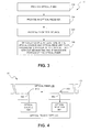
- the functionality may be construed as beginning at block 310, where an optical fiber is provided.
- an optical receiver and an optical source are provided.
- at least one of the optical receiver and optical source is optically coupled to an intermediate portion of the optical fiber without segmenting the optical fiber.
- reflective surfaces are used to couple optical transceivers in accordance with the invention to optical fibers.
- Different types and arrangements of reflective surfaces can be used.
- a material exhibiting a different index of refraction than that of the optical fiber can be arranged in the fiber.
- silver could be used.
- Such a material could form a layer that is inclined with respect to the propagation axis of the fiber to cause optical signals to reflect from the layer to a location offset with respect to the propagation axis.
- the angle of inclination formed between the propagation axis of the fiber and a reflective surface is selected to ensure that an optical signal is directed either from the optical fiber and to the optical transceiver or vice versa.
- the layer can function as a unidirectional reflector (one-way mirror) that reflects optical signals incident upon one side of the layer, while enabling optical signals to pass through the layer from the other side.
- a frequency-dependent grating also could be used. Such an embodiment would be capable of redirecting one or more selected frequencies of optical signals, while permitting optical signals of other frequencies to pass without being redirected.
- an optical fiber can be divided into segments, such as by cutting the fiber to form ends that are inclined with respect to the propagation axis of the fiber.
- One or more of the ends then can be used to form reflective surfaces.
- an end can be coated and/or surrounded by a material exhibiting a different index of refraction than the optical fiber so that optical signals reflect from the end.
- a component such as a diffractive grating, can be attached to an end. The ends then could be optically re-coupled to provide a reflective surface located at an intermediate portion of the fiber.
- the optical signal typically propagates through the side of the optical fiber.
- an optical fiber typically uses a cladding formed about the core of the fiber to maintain propagation of the optical signals along the fiber, the optical fiber used typically exhibits a discontinuity in the cladding.
- an optical fiber with a continuous cladding may be modified, such as by chemically treating the fiber to remove a portion of the cladding or by mechanically removing (nipping away) a portion of the cladding, so that a discontinuity is formed.
- Optical signals then can be directed from the optical fiber at the location of the discontinuity.
- optical fiber 400 of FIG. 4 includes facets 410 and 412.
- Optical transceiver 420 is optically coupled to the fiber via the facets.
- optical source 430 is optically coupled to the fiber via facet 410, which includes a reflective surface 432.
- optical receiver 440 is optically coupled to the optical fiber via facet 412, which includes a reflective surface 442.
- the facets can be chemically and/or mechanically formed, for example.
- optical system 10 directs optical signals toward and receives optical signals from only one end, i . e ., end 450, of the optical fiber.
- Another embodiment that directs optical signals toward and receives optical signals from only one end of an optical fiber is depicted in FIG. 5.
- optical system 10 includes an optical transceiver 500 that is optically coupled to an optical fiber 510.
- Optical transceiver 500 directs optical signals toward and receives optical signals directed from a first end 512 of the optical fiber.
- a first reflective surface 520 of the optical fiber receives optical signal 522 from optical source 530, and directs the optical signal 522 toward the first end of the fiber.
- a reflective surface 540 receives optical signal 542 propagating from the first end 512, and directs this optical signal to optical receiver 550.
- the first reflective surface 520 is formed by an inclined end surface 532 of the optical fiber.
- Inclined end surface 532 can be formed by cleaving the optical fiber.
- optical transceiver 600 includes a housing 610.
- Housing 610 incorporates a base 612 and sidewalls 614 - 620 extending upwardly from the base. Sidewalls 614 and 618 merge to form a curved upper surface 622 of the housing.
- Housing 610 also defines an interior 624 within which an optical source 630 and an optical receiver 640 are arranged.
- sidewall 616 defines an aperture 642 that is sized and shaped for receiving an end and an intermediate portion of an optical fiber.
- an optical fiber 650 is depicted in FIG. 6 as being inserted within the aperture. Insertion of the fiber within the aperture positions the fiber so that the propagation axis of the fiber is offset with respect to the optical source and optical receiver.
- the sidewall 616 supports the optical fiber in this position.
- Optical fiber 650 includes reflective surfaces 652 and 654.
- Reflective surface 652 is aligned with optical source 630 and optically couples the optical source to the fiber.
- reflective surface 654 which is formed by a facet, is aligned with optical receiver 640 and optically couples the optical receiver to the fiber.
- Optical source 630 and optical receiver 640 are supported by a substrate 660 that also is used to support control circuitry 662.
- the control circuitry receives electrical signals via one or more pins 670.
- the control circuitry provides a control input to the optical source so that the optical source can generate optical signals for propagation to optical fiber 650.
- the control circuitry also can control the flow of data from the optical transceiver.
- the optical receiver receives optical signals and converts the optical signals into electrical signals. The electrical signals then are provided to the pins in response to control signals from the control circuitry.
- an analog-to-digital converter can be included for converting the analog electrical signals to digital signals.
- frequency diversity between the optical signals detectable by an optical receiver and the optical signals provided by a corresponding optical source can be used to limit crosstalk.
- an optical receiver may only be able to detect one or more frequencies of optical signals, and the optical source may be incapable of emitting optical signals of the detectable frequencies.
- differential detection of optical signals can be used.
- one or more optical receivers can be used to differentially detect multiple optical signals, each of which exhibits a different frequency.
- multiple optical sources could be provided by the optical transceiver so that the transceiver is capable of emitting optical signals at each of the multiple frequencies.
Landscapes
- Physics & Mathematics (AREA)
- Electromagnetism (AREA)
- Engineering & Computer Science (AREA)
- Computer Networks & Wireless Communication (AREA)
- Signal Processing (AREA)
- General Physics & Mathematics (AREA)
- Optics & Photonics (AREA)
- Optical Couplings Of Light Guides (AREA)
- Optical Communication System (AREA)
Abstract
Description
Claims (10)
- An optical system (10) comprising:an optical transceiver (200) having an optical source (220) and an optical receiver (210); andan optical waveguide (230) having a first end (260) and a second end (270), and an intermediate portion (232) defined between the first end and the second end, at least one of the optical source and the optical receiver being optically coupled to the intermediate portion of the optical waveguide,the optical source being operative to provide optical signals for propagation by the optical waveguide,the optical receiver being operative to receive optical signals propagated by the optical waveguide.
- The optical system of claim 1, wherein the optical waveguide is an optical fiber;
wherein the optical receiver is optically coupled to the intermediate portion of the optical fiber; and
wherein the optical fiber defines a propagation axis (250) extending between the first and second ends, and includes a first reflective surface located along the intermediate portion, the first reflective surface (240) being inclined with respect to the propagation axis and operative to direct optical signals propagating through the optical fiber to the optical receiver. - The optical system of claim 2, wherein the first reflective surface is a portion of a facet formed in the optical fiber.
- The optical system of one of the preceding claims, wherein the optical source is optically endcoupled to the optical fiber.
- The optical system of one of the preceding claims, wherein the optical receiver lacks an ability to detect optical signals originating from the optical source.
- The optical system of claim 1, wherein the optical waveguide is an optical fiber;
wherein the optical receiver is optically coupled to the intermediate portion of the optical fiber; and
wherein the optical fiber defines a propagation axis extending between the first and second ends, and includes a first reflective surface (240) located along the intermediate portion and a second reflective surface (244), the first reflective surface being inclined with respect to the propagation axis and operative to direct optical signals propagating through the optical fiber to the optical receiver, the second reflective surface being inclined with respect to the propagation axis and operative to direct optical signals from the optical source to the optical fiber. - The optical system of claim 6, wherein the second reflective surface is located at the first end of the optical fiber, and the optical source is offset with respect to the propagation axis of the optical fiber.
- The optical system of one of the preceding claims, further comprising:means for directing optical signals from the optical waveguide to the optical receiver; andmeans for directing optical signals from the optical source to the optical waveguide.
- An optical transceiver (600) for use with an optical fiber (650), the optical fiber having a first end and a second end, a propagation axis extending between the first end and the second end, and an intermediate portion defined between the first end and the second end, said optical transceiver comprising:a housing (610) having a base (612) and sidewalls (614, 616, 618, 620) extending upwardly from said base, a first of said sidewalls defining an aperture (642), said aperture being sized and shaped for receiving the first end and at least a portion of the intermediate portion of the optical fiber;an optical source (630) arranged within said housing such that said optical source is offset with respect to the propagation axis of the optical fiber, said optical source being operative to receive control signals and provide optical signals for propagation by the optical fiber in response to said control signals; andan optical receiver (640) arranged within said housing such that said optical receiver is offset with respect to the propagation axis of the optical fiber, said optical receiver being operative to receive optical signals propagated by the optical fiber.
- A method for communicating optical signals comprising:providing an optical fiber (230) having a first end (260) and a second end (270), and an intermediate portion (232) defined between the first end and the second end;providing an optical transceiver (200) having an optical receiver (210) and an optical source (220); andoptically coupling at least one of the optical receiver and the optical source to the intermediate portion of the optical fiber without segmenting the intermediate portion of the optical fiber.
Applications Claiming Priority (2)
| Application Number | Priority Date | Filing Date | Title |
|---|---|---|---|
| US133826 | 2002-04-26 | ||
| US10/133,826 US7184669B2 (en) | 2002-04-26 | 2002-04-26 | Optical transceiver systems and methods |
Publications (2)
| Publication Number | Publication Date |
|---|---|
| EP1357684A2 true EP1357684A2 (en) | 2003-10-29 |
| EP1357684A3 EP1357684A3 (en) | 2005-04-06 |
Family
ID=28791028
Family Applications (1)
| Application Number | Title | Priority Date | Filing Date |
|---|---|---|---|
| EP02023494A Ceased EP1357684A3 (en) | 2002-04-26 | 2002-10-21 | Optical transceiver systems and methods |
Country Status (3)
| Country | Link |
|---|---|
| US (1) | US7184669B2 (en) |
| EP (1) | EP1357684A3 (en) |
| JP (1) | JP2003332994A (en) |
Families Citing this family (17)
| Publication number | Priority date | Publication date | Assignee | Title |
|---|---|---|---|---|
| US7006746B2 (en) * | 2002-08-29 | 2006-02-28 | Micron Technology, Inc. | Waveguide for thermo optic device |
| US7120336B2 (en) | 2002-08-29 | 2006-10-10 | Micron Technology, Inc. | Resonator for thermo optic device |
| US7447440B2 (en) * | 2004-05-17 | 2008-11-04 | Cisco Technology, Inc. | Multiple channel optical transceiver modules |
| JP4549922B2 (en) * | 2005-05-19 | 2010-09-22 | 本多通信工業株式会社 | Optical transmission line connection module |
| WO2007002603A2 (en) * | 2005-06-24 | 2007-01-04 | The Board Of Trustees Of The University Of Illinois | Optically-triggered power system and devices |
| JP4384127B2 (en) * | 2006-03-22 | 2009-12-16 | トヨタ自動車株式会社 | A module in which a plurality of circuit boards are laminated at a predetermined distance, and an optical connector for the module |
| JP5029193B2 (en) * | 2007-07-31 | 2012-09-19 | 日本電気株式会社 | Optical transceiver subassembly and optical transceiver module |
| US7802927B2 (en) * | 2008-05-30 | 2010-09-28 | Corning Cable Systems Llc | Bent optical fiber couplers and opto-electrical assemblies formed therefrom |
| JP2010107602A (en) * | 2008-10-29 | 2010-05-13 | Fuji Xerox Co Ltd | Optical transmission apparatus and electronic device |
| KR101872745B1 (en) | 2010-04-28 | 2018-06-29 | 후아웨이 테크놀러지 컴퍼니 리미티드 | Cross-talk reduction in a bidirectional optoelectronic device |
| CN102714542B (en) * | 2010-06-25 | 2015-08-19 | Hoya美国公司 | Crosstalk in bidirectional optoelectronic device reduces |
| EP2614604B1 (en) | 2010-09-06 | 2017-08-16 | Huawei Technologies Co., Ltd. | Cross-talk reduction in a bidirectional optoelectronic device |
| CN103858035A (en) | 2011-10-28 | 2014-06-11 | Hoya美国公司 | Optical waveguide splitter on a waveguide substrate for attenuating a light source |
| US9011025B2 (en) * | 2011-12-19 | 2015-04-21 | Avago Technologies General Ip (Singapore) Pte. Ltd. | Modified transistor outline (TO)-can assembly for use in optical communications and a method |
| TWI562393B (en) * | 2011-12-26 | 2016-12-11 | Hon Hai Prec Ind Co Ltd | Photoelectric converter |
| CN103185931B (en) * | 2011-12-27 | 2016-03-02 | 鸿富锦精密工业(深圳)有限公司 | Photoelectric commutator |
| FR3105666B1 (en) * | 2019-12-23 | 2022-01-14 | Latelec | Optical transceiver module |
Family Cites Families (20)
| Publication number | Priority date | Publication date | Assignee | Title |
|---|---|---|---|---|
| CH599558A5 (en) | 1976-03-16 | 1978-05-31 | Patelhold Patentverwertung | |
| US4549782A (en) * | 1983-06-06 | 1985-10-29 | At&T Bell Laboratories | Active optical fiber tap |
| GB2168165B (en) | 1984-12-10 | 1988-08-10 | Electronic Components Ltd | Tap for data transmission system |
| US4800262A (en) | 1987-12-31 | 1989-01-24 | American Telephone And Telegraph Company, At&T Bell Laboratories | Tri-state optical device with quantum well absorption |
| WO1990002349A1 (en) | 1988-08-31 | 1990-03-08 | Raynet Corporation | Method of deforming a polymer optical fiber to form taps |
| US5105293A (en) | 1990-10-02 | 1992-04-14 | At&T Bell Laboratories | Differential optical signal transmission using a single optical fiber |
| US5122893A (en) | 1990-12-20 | 1992-06-16 | Compaq Computer Corporation | Bi-directional optical transceiver |
| JPH04372907A (en) * | 1991-06-21 | 1992-12-25 | Canon Inc | Waveguide type branching-coupling element |
| JPH07104146A (en) * | 1993-10-01 | 1995-04-21 | Ngk Insulators Ltd | Optical component manufacturing method |
| US5734765A (en) * | 1994-07-26 | 1998-03-31 | Ceramoptec Industries Inc. | Damage resistant infrared fiber delivery device and system |
| US5854865A (en) * | 1995-12-07 | 1998-12-29 | The United States Of America As Represented By The Secretary Of The Navy | Method and apparatus for side pumping an optical fiber |
| JPH10153720A (en) * | 1996-11-25 | 1998-06-09 | Sony Corp | Optical transceiver |
| US5963349A (en) | 1997-01-27 | 1999-10-05 | Lucent Technologies Inc. | Inexpensive single-fiber bidirectional data link |
| JPH1168164A (en) | 1997-08-26 | 1999-03-09 | Rohm Co Ltd | Module for bidirectional optical communication |
| US6081638A (en) * | 1998-07-20 | 2000-06-27 | Honeywell Inc. | Fiber optic header with integrated power monitor |
| EP1008876A3 (en) | 1998-12-11 | 2003-03-26 | Litton Systems, Inc. | Optical fiber tap and method of tapping an optical signal from an optical cable |
| US6757467B1 (en) * | 2000-07-25 | 2004-06-29 | Optical Air Data Systems, Lp | Optical fiber system |
| JP2002050785A (en) * | 2000-08-01 | 2002-02-15 | Sumitomo Electric Ind Ltd | Semiconductor light receiving element |
| EP1393108A1 (en) * | 2001-05-23 | 2004-03-03 | Infineon Technologies AG | Electro-optical module for the transmission and/or receiving of optical signals from at least two optical data channels |
| US6754417B2 (en) * | 2002-04-24 | 2004-06-22 | Agilent Technologies, Inc. | Optical fiber tap capable of random placement along an optical fiber |
-
2002
- 2002-04-26 US US10/133,826 patent/US7184669B2/en not_active Expired - Lifetime
- 2002-10-21 EP EP02023494A patent/EP1357684A3/en not_active Ceased
-
2003
- 2003-04-23 JP JP2003118125A patent/JP2003332994A/en not_active Withdrawn
Also Published As
| Publication number | Publication date |
|---|---|
| JP2003332994A (en) | 2003-11-21 |
| US7184669B2 (en) | 2007-02-27 |
| US20040213516A1 (en) | 2004-10-28 |
| EP1357684A3 (en) | 2005-04-06 |
Similar Documents
| Publication | Publication Date | Title |
|---|---|---|
| US7184669B2 (en) | Optical transceiver systems and methods | |
| US10317625B2 (en) | Polymer waveguide (PWG) connector assembly having both cores and cladding partially exposed | |
| US6956996B2 (en) | Tri-state optical systems and methods | |
| JP2867859B2 (en) | Optical transceiver module for bidirectional transmission | |
| US6415076B1 (en) | Mode conditioning patch for facilitating signal transmission from single mode optical fiber to multimode optical fiber | |
| US6122420A (en) | Optical loopback apparatus | |
| US4955014A (en) | Broadband optical communication system, particularly in the subscriber area | |
| JP2013195642A (en) | Optical coupling structure and optical transmission device | |
| EP1229363A2 (en) | Optical coupling structure | |
| JPH11271548A (en) | Two-way optical communication device and two-way optical communication device | |
| US4765706A (en) | Optical communications system including a directional coupler | |
| JPS61158306A (en) | Numerical aperture convertor | |
| JP3261097B2 (en) | Acousto-optic modulator device | |
| JPH1152158A (en) | Waveguide type optical circuit | |
| KR100557407B1 (en) | Bidirectional Optical Transmission Module | |
| JPH10232317A (en) | Waveguide device | |
| JPH05203830A (en) | Optical multiplexer demultiplexer | |
| JP2000193850A (en) | Optical fiber connecting device and optical fiber connecting method | |
| US7324727B2 (en) | Planar lightwave circuit having optical filter | |
| EP1589359A1 (en) | Optical waveguide and optical transmitting/receiving module | |
| JP2000047065A (en) | Mode conditioner | |
| JP3125902B2 (en) | Star type optical wiring circuit | |
| US20040252945A1 (en) | Optical waveguide element with directional coupler | |
| JPH0697561A (en) | Optical output stabilization method for waveguide type bidirectional transmission module | |
| SUMIDA et al. | High-silica guided-wave hybrid optical transmitting-receiving module |
Legal Events
| Date | Code | Title | Description |
|---|---|---|---|
| PUAI | Public reference made under article 153(3) epc to a published international application that has entered the european phase |
Free format text: ORIGINAL CODE: 0009012 |
|
| AK | Designated contracting states |
Kind code of ref document: A2 Designated state(s): AT BE BG CH CY CZ DE DK EE ES FI FR GB GR IE IT LI LU MC NL PT SE SK TR |
|
| AX | Request for extension of the european patent |
Extension state: AL LT LV MK RO SI |
|
| PUAL | Search report despatched |
Free format text: ORIGINAL CODE: 0009013 |
|
| AK | Designated contracting states |
Kind code of ref document: A3 Designated state(s): AT BE BG CH CY CZ DE DK EE ES FI FR GB GR IE IT LI LU MC NL PT SE SK TR |
|
| AX | Request for extension of the european patent |
Extension state: AL LT LV MK RO SI |
|
| RIC1 | Information provided on ipc code assigned before grant |
Ipc: 7G 02B 6/42 B Ipc: 7H 04B 10/213 A |
|
| 17P | Request for examination filed |
Effective date: 20050907 |
|
| AKX | Designation fees paid |
Designated state(s): DE FR GB |
|
| 17Q | First examination report despatched |
Effective date: 20051007 |
|
| RAP1 | Party data changed (applicant data changed or rights of an application transferred) |
Owner name: AVAGO TECHNOLOGIES FIBER IP (SINGAPORE) PTE. LTD. |
|
| 17Q | First examination report despatched |
Effective date: 20051007 |
|
| STAA | Information on the status of an ep patent application or granted ep patent |
Free format text: STATUS: THE APPLICATION HAS BEEN REFUSED |
|
| 18R | Application refused |
Effective date: 20091004 |