EP1357537A2 - Stream data processing system and method - Google Patents
Stream data processing system and method Download PDFInfo
- Publication number
- EP1357537A2 EP1357537A2 EP03009341A EP03009341A EP1357537A2 EP 1357537 A2 EP1357537 A2 EP 1357537A2 EP 03009341 A EP03009341 A EP 03009341A EP 03009341 A EP03009341 A EP 03009341A EP 1357537 A2 EP1357537 A2 EP 1357537A2
- Authority
- EP
- European Patent Office
- Prior art keywords
- filter
- stream data
- data
- flow
- capture
- Prior art date
- Legal status (The legal status is an assumption and is not a legal conclusion. Google has not performed a legal analysis and makes no representation as to the accuracy of the status listed.)
- Granted
Links
Images



Classifications
-
- G—PHYSICS
- G10—MUSICAL INSTRUMENTS; ACOUSTICS
- G10H—ELECTROPHONIC MUSICAL INSTRUMENTS; INSTRUMENTS IN WHICH THE TONES ARE GENERATED BY ELECTROMECHANICAL MEANS OR ELECTRONIC GENERATORS, OR IN WHICH THE TONES ARE SYNTHESISED FROM A DATA STORE
- G10H7/00—Instruments in which the tones are synthesised from a data store, e.g. computer organs
- G10H7/002—Instruments in which the tones are synthesised from a data store, e.g. computer organs using a common processing for different operations or calculations, and a set of microinstructions, e.g. programs, to control the sequence thereof
-
- G—PHYSICS
- G10—MUSICAL INSTRUMENTS; ACOUSTICS
- G10H—ELECTROPHONIC MUSICAL INSTRUMENTS; INSTRUMENTS IN WHICH THE TONES ARE GENERATED BY ELECTROMECHANICAL MEANS OR ELECTRONIC GENERATORS, OR IN WHICH THE TONES ARE SYNTHESISED FROM A DATA STORE
- G10H1/00—Details of electrophonic musical instruments
- G10H1/02—Means for controlling the tone frequencies, e.g. attack or decay; Means for producing special musical effects, e.g. vibratos or glissandos
- G10H1/06—Circuits for establishing the harmonic content of tones, or other arrangements for changing the tone colour
- G10H1/12—Circuits for establishing the harmonic content of tones, or other arrangements for changing the tone colour by filtering complex waveforms
- G10H1/125—Circuits for establishing the harmonic content of tones, or other arrangements for changing the tone colour by filtering complex waveforms using a digital filter
-
- G—PHYSICS
- G10—MUSICAL INSTRUMENTS; ACOUSTICS
- G10H—ELECTROPHONIC MUSICAL INSTRUMENTS; INSTRUMENTS IN WHICH THE TONES ARE GENERATED BY ELECTROMECHANICAL MEANS OR ELECTRONIC GENERATORS, OR IN WHICH THE TONES ARE SYNTHESISED FROM A DATA STORE
- G10H2240/00—Data organisation or data communication aspects, specifically adapted for electrophonic musical tools or instruments
- G10H2240/171—Transmission of musical instrument data, control or status information; Transmission, remote access or control of music data for electrophonic musical instruments
- G10H2240/281—Protocol or standard connector for transmission of analog or digital data to or from an electrophonic musical instrument
- G10H2240/285—USB, i.e. either using a USB plug as power supply or using the USB protocol to exchange data
-
- G—PHYSICS
- G10—MUSICAL INSTRUMENTS; ACOUSTICS
- G10H—ELECTROPHONIC MUSICAL INSTRUMENTS; INSTRUMENTS IN WHICH THE TONES ARE GENERATED BY ELECTROMECHANICAL MEANS OR ELECTRONIC GENERATORS, OR IN WHICH THE TONES ARE SYNTHESISED FROM A DATA STORE
- G10H2250/00—Aspects of algorithms or signal processing methods without intrinsic musical character, yet specifically adapted for or used in electrophonic musical processing
- G10H2250/541—Details of musical waveform synthesis, i.e. audio waveshape processing from individual wavetable samples, independently of their origin or of the sound they represent
- G10H2250/621—Waveform interpolation
-
- G—PHYSICS
- G10—MUSICAL INSTRUMENTS; ACOUSTICS
- G10H—ELECTROPHONIC MUSICAL INSTRUMENTS; INSTRUMENTS IN WHICH THE TONES ARE GENERATED BY ELECTROMECHANICAL MEANS OR ELECTRONIC GENERATORS, OR IN WHICH THE TONES ARE SYNTHESISED FROM A DATA STORE
- G10H2250/00—Aspects of algorithms or signal processing methods without intrinsic musical character, yet specifically adapted for or used in electrophonic musical processing
- G10H2250/541—Details of musical waveform synthesis, i.e. audio waveshape processing from individual wavetable samples, independently of their origin or of the sound they represent
- G10H2250/631—Waveform resampling, i.e. sample rate conversion or sample depth conversion
Definitions
- the present invention relates to a stream data processing system operable in such a way that stream data (moving picture data, musical sound data and the like) is entered (captured) thereinto from an input device, a certain process operation is carried out with respect to the captured stream data, and thereafter, the processed stream data is outputted from a separate output device from the input device, and further relates to a stream data processing method, stream data processing program, and computer readable recording medium for storing the stream data processing program.
- stream data such as multimedia data
- data stream is synchronized based upon certain timing information and is input and output, and processed.
- timing information physical clocks, and time stamp information contained in certain stream data are provided.
- output data may not have a desirable format due to overflow or depletion of the data.
- output data may not have a desirable format due to overflow or depletion of the data.
- an effector filter contained in an audio data processing system is formed in a user mode since the system has an user interface function which allows the user to set effects.
- this "kernel mode” implies such an operation mode to which a very high priority is given in an operating system (OS) such as WINDOWS (registered trademark) of Microsoft Corporation, namely such an operation mode that a code can directly access all of hardware and also all of memories.
- OS operating system
- WINDOWS registered trademark
- this "user mode” implies such an operation mode whose priority is set to a low level in the OS such as WINDOWS (registered trademark) , namely such an operation mode that a code cannot directly access hardware.
- the below-mentioned problem may occur. That is, since the audio data transmission between a filter formed in a kernel mode and a filter formed in a user mode and/or between filters formed in the user mode takes large load for processing in comparison with the data transmission between the filters formed in the kernel mode, throughput of the effector filter varies due to influence from other task, and the audio data may be overflown, or depleted before/after the effector filter, so that stream data cannot be outputted in an ideal format, and/or noise may be produced.
- Japanese Patent Publication No. Hei-10-283199 discloses the synchronizing apparatus.
- This conventional synchronizing apparatus is designed to minimize lag of the output timing of the plural stream data in such a manner that while this synchronizing apparatus owns three sets of different time values, i.e., the positional time value, the physical time value, and the relative time value, these three time values are commonly utilized in large numbers of devices.
- This positional time value corresponds to such a time value produced based upon time interval information related to a data stream, and reflects a position of the data stream to be processed.
- the physical time value corresponds to such a time value produced based upon a hardware oscillator, or a clock.
- the relative time value is to provide a designated time value such as the positional time value in connection with a reference time value.
- the present invention has been made to solve the above-explained problems, and therefore, has an object to minimize deviation of input/output timing without using complex construction for the clock control.
- the invention is characterized by having the following arrangement.
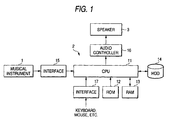
- Fig. 1 is a block diagram for indicating a hardware structure of a stream data processing system according to a first embodiment of the present invention.
- the stream data processing system according to the embodiment is established by such an assumption. That is, in this embodim ent, stream data corresponds to musical sound data outputted from such a musical instrument as an electric guitar and an electronic piano.
- This stream data (musical sound data) is processed by a personal computer (PC) 2, and then, the processed stream data is outputted from a speaker 3.
- the personal computer (PC) 2 contains a CPU 11, a ROM 12, a RAM 13, a hard disk drive (HDD) 14, and the like.
- the CPU 11 may execute various sorts of programs under control of an operating system (OS).
- OS operating system
- the ROM 12 is a nonvolatile memory which stores thereinto a boot program initiated when a power supply is turned ON, and other data/programs.
- the RAM 13 temporarily stores thereinto various sorts of activated programs, and also provides work areas used to process various sorts of data.
- the HDD 14 corresponds to a drive apparatus capable of driving a magnetic disk used to store thereinto the operating system and various sorts of programs.
- An interface (I/F) 15 converts the musical sound data derived from the musical instrument 1 based upon a predetermined system and then outputs the converted musical sound data to the CPU 11.
- An audio controller 16 corresponds to a control apparatus for executing an output processing operation of a musical sound signal. Input data entered from various sorts of input apparatus (mouse, keyboard, and the like) is inputted via the I/F 17 to the CPU 11.
- Fig. 2 shows the software structure of the program executed by the PC2, while including a correspondence relationship with respect to the hardware structure.
- API Application Program Interface
- the software is constituted by producing a plurality of objects which is referred to as “filters”, and also, the respective filters are connected to each other by architecture called as a "filter graph" (not shown).
- the software according to the embodiment is arranged by a capture filter 21, an effector filter 22, a flow-rate monitoring filter 23, and a renderer filter 24.
- the effector filter 22 is formed in a user mode and the remaining filters are formed in a kernel mode, the effector filter 22 may be formed in the kernel mode.
- the filters 21 to 24 are set to be operated under predetermined clock of same frequency, however, in the frequency of the actual clock, slight deviation exists among the filters due to various error factors.
- the capture filter 21 has such a function that musical sound data entered from the musical instrument 1 is acquired, and the acquired musical sound data is converted into such a format data capable of being recognized by the effector filter 22 and other filters provided at a post stage, and then, this format data is outputted.
- the capture filter 21 is provided with a USB buffer 21a, a ring buffer 21b, and an output queuing buffer 21c.
- the musical sound data derived from the musical instrument 1 is firstly buffered by the USB buffer 21a, and then, is sequentially transferred to the ring buffer 21b and the output queuing buffer 21c.
- the ring bugger 21b is used for processing such as format conversion of input data.
- the structure of the output queuing buffer 21c may be changed in various manners. In this embodiment, the structure of this output queuing buffer 21c is made of such an assumption that 8 pieces of 1024-bit buffers are allocated thereto.
- the effector filter 22 is employed so as to apply an arbitrary change to the musical sound data outputted from the capture filter 21.
- This effector filter 22 is equipped with an input buffer 22a, a ring filter 22b, and an output queuing buffer 22c.
- a structure of the input buffer 22a may be made similar to the structure of the output queuing buffer 21c employed in the capture filter 21 at a prestage of this input buffer 22a.
- the input buffer 22a transfers/receives buffered data with respect to the output queuing buffer 21c based on a predetermined clock. Then, the musical sound data is sequentially transferred from the input buffer 22a via the ring buffer 22b to the output queuing buffer 22c.
- the ring buffer 22b is used for processing such as format conversion of input data.
- a structure of the output buffer 22c may be made similar to the structures of the output queuing buffer 21c and the input buffer 22a. Since this effector filter 22 is formed in various structures in order to meet various requirements of users, and also, corresponds to such a software structural portion which is directly operated by the users, in many of cases, this effector filter 23 is normally formed in the user mode.
- the flow-rate monitoring filter 23 is connected between the effector filter 22 and the renderer filter 24.
- This flow-rate monitoring filter 23 is equipped with an input buffer 23a, a ring filter 23b, and an output queuing buffer 23c. Both a structure of the input buffer 23a and a structure of the output buffer 23c may be made similar to the structures of the input buffer 22a and the output buffer 22c.
- the input buffer 23a transfers/receives buffed data with respect to the output queuing buffer 22c employed in the effector filter 22 provided at a prestage thereof based on a predetermined clock. Subsequently, the data transfer operation is sequentially carried out from the input buffer 23a via the ring buffer 23b to the output queuing buffer 23c.
- the flow-rate monitoring filter 23 owns such a function capable of monitoring a flow rate of data contained in a data stream of the stream data processing system constituted by the filters 21 to 24, and of outputting (feeding back) a monitoring result to the capture filter 21 and/or the effector filter 22. A detailed function of this flow-rate monitoring filter 23 will be explained later.
- the renderer filter 24 corresponds to a filter used to output such stream data having a format recognizable by an audio controller 16, and is equipped with a buffer 24a for buffering thereinto data to be rendered.
- a structure of the buffer 24a may be made similar to that of the output queuing buffer 23c and the like provided at the prestage thereof.
- the buffer 24a transfers/receives buffered data with respect to the output queuing buffer 23c, and properly outputs data to the audio controller 16 based on a predetermined clock.
- the filters 21 to 24 are driven by basically same operating clock, however due to various error factors, slight deviation between frequencies may be occurred.
- the data are transferred and received between the buffer of the upper filer and the buffer of the lower filter, the data is not pooled in the input buffer of the lower filter but pooled in the output queuing butter of the upper filter.
- Amanager 25 corresponds to such a software structural portion capable of managing data transmission operations among the respective filters, for instance, controlling monitoring timing of the flow-rate monitoring filter 23, and controlling stream data outputted from the capture filter 21 and stream data inputted/outputted into/from the renderer filter 24 based upon information related to the monitoring operation, e.g., monitoring results and the like.
- the stream data processing program is read out from the HDD 14, and thus, the capture filter 21, the ejector filter 22, the flow-rate monitoring filter 23, the renderer filter 24, and the like are produced. Then, when the musical sound data is entered from the musical instrument 1 to the PC 2, this musical sound data is transferred through the capture filter 21, the ejector filter 22, the flow-rate monitoring filter 23, and the renderer filter 24 in this order, and then, the filteredmusical sound data is outputted.
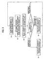
- the flow-rate monitoring filter 23 counts a total number "Cr" of buffers under renderingprocess among the plural filters 24aprovided in the renderer filter 24 (step S1).
- a reason why the number "Cr" of buffers under rendering process in the input buffer 24a is counted is because, in the case that the difference between clock of the capture filter 21 and clock of the renderer filter 24 exists, influence thereof is more likely to be reflected. That is, when the clock of the capture filter is faster than the clock of the renderer clock, data is been pooled in the output queuing buffer 23c and number of the renderer filter which is in the rendering process decreases. In this case, determination is made so that flow data is high. On the other hand, when the clock of the capture filer is slower than the clock of the renderer clock, data pooled in the output queuing buffer 23c gets less and number of the renderer filter which is in the rendering process increases.
- this flow-rate monitoring filter 23 changes variables of "insertpoints" and "rejectpoints", which control a data flow rate.
- Counting the number "Cr" of the buffers under the rendering process in the buffer 24a may be performed by counting the number of output queuing buffer 23c in the flow-rate monitoring filter 23.
- time Tw from buffer being entered into queue of the output queuing buffer 23c of the flow-rate monitoring filter 23, to the buffer being output to renderer filter 24 is used to compute (count) the number "Cr" of buffer in the rendering process in the buffer 24a.
- the time Tw is large, the number of the output queuing buffer 23c of the flow-rate monitoring filter 23 is large, that is, the buffer number Cr in the operation of the rendering process is small.
- the Tw is small, the number of the output queuing buffer 23c of the flow-rate monitoring filter 23 is small, that is, the buffer number Cr in the rendering process is large.
- the flow-rate monitoring filter 23 counts a total number of buffers which are queued in the output queuing buffer 23c, and a count value when the buffer does not carry out the queuing operation for a predetermined time period is determined as a buffer total number Cb which is used for the data transmission between the output queuing buffer 23c and the renderer filter 24.
- the buffer number "Cr" can be calculated in higher precision.
- the flow-rate monitoring filter 23 determines both the variable “insertpoints” and the variable “rejectpoints” based upon this calculated value "Cr" (step S2).
- the flow-rate monitoring filter 23 outputs these variables "insertpoints" and "rejectpoints” to the capture filter 21 (step S3).
- the capture filter 21 judges whether the variables "insertpoints" and rejectpoints" is equal to or larger than 0 (step S4).
- the capture filter 21 executes a data inserting process operation for inserting data (step S5).
- a total data number of a data stream "S" of a constant section is assumed as "N”, which has been captured by the USB buffer 21a of the capture filter 21
- M N + p.
- the capture filter 21 executes a data deleting process operation for deleting data (step S6).
- a length of the data stream "S" of the constant section is assumed as "N”, which has been captured by the capture filter 21
- the process operation is returned to the previous step S1 in which the counting operation of the buffer number "Cr" is again carried out.
- the buffering condition of the buffer 24a employed in the renderer filter 24 is monitored by the flow rate monitoring filter 23, and then, the data is deleted or inserted by way of the interpolation method in the capture filter 21 based upon the monitoring result.
- the data stream is overflown and/or is depleted which is caused by a difference of clock cycle of the capture filter and the renderer filter.
- the data may be deleted at the flow-rate monitoring filter 23.
- process of deletion and insertion of the data received from the input buffer 23a is carried out by using the ring buffer 23b, and the processed data is transmitted to the output queuing buffer 23c.
- the interpolation data may be alternatively obtained by way of an integer calculation.
- Filter construction of the second embodiment is similar to that of the first embodiment (Fig. 2), however, different from the first embodiment in that instead of the flow-rate monitoring filter 23 monitoring the input buffer 24a of the renderer filter 24, the flow-rate monitoring filter 23 monitors the number "Cr'" of the buffer of the input buffer of the effector filter formed in the user mode, and deletes or insets the data in the capture filter 21 by way of the interpolation method based on the number "Cr'" of the buffer.
- the flow-rate monitoring filter 23 counts the number "Cr'" of the plural input buffers in the effector filter 22 (step S11).
- the flow-rate monitoring filter 23 determines both the variable “insertpoints” and the variable “rejectpoints” based upon this calculated value "Cr'" (step S12).
- the flow-rate monitoring filter 23 outputs these variables "insertpoints" and "rejectpoints” to the capture filter 21 (step S13).
- step S16 the capture filter 21 executes a data deleting process operation for deleting data.
- a length of the data stream "S" of the constant section is assumed as "N”, which has been captured by the capture filter 21
- M N - p.
- the process operation is returned to the previous step S1 in which the counting operation of the buffer number "Cr" is again carried out.
- a method of adding and deleting data in the capture filter 21 by way of the interpolation method is same as the method described in the first embodiment (Fig. 4).
- the effector filter 22 overflow or depletion of data tends to be occurred since the throughput changes by the influence of another task. Particularly, in the case that the effector filter 22 is formed in the user mode or is formed in the kernel mode but the priority thereof is low, the tendency of the overflow and depletion is high. Therefore, in the second embodiment, when the flow rate is lower than a predetermined value, the above-mentioned data inserting process or data deleting process is executed, and when the flow rate is higher than a predetermined value, in addition to the data adding process or the data deleting process by the data interpolation method, thinning operation for thinning the buffer itself is executed. At this time, to remove noise, preferably, cross-fading processing or the like may be executed at front of rear of the section corresponding to the deleted buffer. Incidentally, the process for thinning the buffer itself may be executed at the effector filter 22.
- the present invention has described such a case that the musical sound data is processed as one example of the stream data, but the present invention is not limited thereto.
- the present invention may be alternatively applied to such a case that picture data is processed.
- the present invention may be applied to such a case that a composite signal made of musical sound data and picture data, such as picture information equipped with acoustic data (effect sound), is processed.
- the capture filter 21, the effector filter 22, the flow-rate monitoring filter 23 and the renderer filter 24 are provided, and the flow-rate monitoring filter 23 is provided at prestage of the renderer filter.
- the flow-rate monitoring filter does not have to be provided at prestage of the renderer filter, and another filter other than the filter described above may be provided between the flow-rate monitoring filter 24 and the renderer filter 24.
- the flow-rate monitoring filter 23 is provided at a prestage of the filter to be monitored and located as near as possible to the renderer filter.
- linear interpolation method has been utilized as the data interpolation method in the above-described embodiment, other interpolation methods may be utilized, for example, the Lagrange's interpolation method and the spline interpolation method may be used.
- USB buffer 21a has been used in the above-described embodiment.
- other buffers such as an IEEE1394 interface may be employed.
- the delays occurred in the input/output timing of the stream data can be minimized.
Landscapes
- Engineering & Computer Science (AREA)
- Physics & Mathematics (AREA)
- Acoustics & Sound (AREA)
- Multimedia (AREA)
- General Engineering & Computer Science (AREA)
- Complex Calculations (AREA)
- Signal Processing For Digital Recording And Reproducing (AREA)
- Television Systems (AREA)
Abstract
Description
Claims (10)
- A stream data processing system constructed of mutually-connected software filter, the mutually-connected software filter comprising:a capture filter which holds stream data entered from external;a renderer filter which outputs the stream data outside the mutually-connected software filters; anda flow-rate monitoring filter arranged between the renderer filter and the capture filter, which monitors a flow rate of the stream data flowing between the capture filter and the renderer filter, wherein the software filters adjust the flow rate based upon information related to the monitoring operation.
- The stream data processing system according to claim 1, wherein the flow-rate monitoring filter judges the flow rate based upon buffer information of a filter arranged at a post stage of the flow-rate monitoring filter.
- The stream data processing system according to claim 1, wherein the flow-rate monitoring filter feeds back information related to the flow rate of the stream data to the capture filter.
- The stream data processing system according to claim 3, wherein the capture filter partially deletes data from the stream data, or inserts data into the stream data based upon the information which is fed back, so that the software filters adjust the flow rate of the stream data.
- The stream data processing system according to claim 4, wherein the capture filter inserts or deletes the data by way of an interpolation.
- The stream data processing system according to claim 2, wherein the flow-rate monitoring filter acquires the buffer information under such a condition that outputting of the stream data to the filter arranged at the post stage is stopped.
- The stream data processing system according to claim 1, wherein the flow-rate monitoring filter judges the flow rate based on buffer information of a file created by a user mode.
- The stream data processing system according to claim 7, whereinthe flow-ratemonitoringfilterfeedsback information related to flow rate of the stream data to the capture filter,based on the fed-back information, the capture filter deletes a part of data from the stream data or inserts data into the stream data when the flow rate is lower than a predetermined values, and adjusts the flow rate of the stream data by executing thinning operation on the buffer.
- A stream data processing method of producing mutually-connected software filters to process stream data, the method comprising:a step of producing a capture filter which holds externally-entered stream data;a step of producing a renderer filter which outputs the stream data outside the mutually-connected software filters;a step of producing a flow-rate monitoring filter arranged between the renderer filter and the capture filter, which monitors a flow rate of the stream data flowing between the capture filter and the renderer filter; anda step of adjusting the flow rate based upon information related to the monitoring operation.
- A computer readable recording medium storing a stream data processing program for producing mutually-connected software filters, which causes a computer to execute:a step of producing a capture filter which holds externally-entered stream data;a step of producing a renderer filter which outputs of stream data outside of mutually-connected software filters;a step of producing a flow-rate monitoring filter arranged between the renderer filter and the capture filter, which monitors a flow rate of the stream data flowing between the capture filter and the renderer filter; anda step of adjusting the flow rate basedupon information related to the monitoring operation.
Applications Claiming Priority (2)
| Application Number | Priority Date | Filing Date | Title |
|---|---|---|---|
| JP2002126886 | 2002-04-26 | ||
| JP2002126886 | 2002-04-26 |
Publications (3)
| Publication Number | Publication Date |
|---|---|
| EP1357537A2 true EP1357537A2 (en) | 2003-10-29 |
| EP1357537A3 EP1357537A3 (en) | 2004-02-04 |
| EP1357537B1 EP1357537B1 (en) | 2008-05-14 |
Family
ID=28786832
Family Applications (1)
| Application Number | Title | Priority Date | Filing Date |
|---|---|---|---|
| EP03009341A Expired - Lifetime EP1357537B1 (en) | 2002-04-26 | 2003-04-24 | Stream data processing system and method |
Country Status (3)
| Country | Link |
|---|---|
| US (1) | US7590459B2 (en) |
| EP (1) | EP1357537B1 (en) |
| DE (1) | DE60320889D1 (en) |
Cited By (1)
| Publication number | Priority date | Publication date | Assignee | Title |
|---|---|---|---|---|
| WO2007073351A1 (en) * | 2005-12-19 | 2007-06-28 | Creative Technology Ltd | A portable media player |
Families Citing this family (1)
| Publication number | Priority date | Publication date | Assignee | Title |
|---|---|---|---|---|
| US20060075507A1 (en) * | 2001-09-06 | 2006-04-06 | Sonic Solutions | Secure protocols for use with microsoft directshow filters |
Family Cites Families (10)
| Publication number | Priority date | Publication date | Assignee | Title |
|---|---|---|---|---|
| JPS61156949A (en) | 1984-12-27 | 1986-07-16 | Matsushita Electric Ind Co Ltd | Packetized voice communication system |
| TW267228B (en) * | 1994-06-02 | 1996-01-01 | Matsushita Electric Industrial Co Ltd | Data sample series access apparatus |
| JP3658826B2 (en) * | 1995-12-21 | 2005-06-08 | ヤマハ株式会社 | Music generation method |
| US5815689A (en) * | 1997-04-04 | 1998-09-29 | Microsoft Corporation | Method and computer program product for synchronizing the processing of multiple data streams and matching disparate processing rates using a standardized clock mechanism |
| US6807667B1 (en) * | 1998-09-21 | 2004-10-19 | Microsoft Corporation | Method and system of an application program interface for abstracting network traffic control components to application programs |
| US6785230B1 (en) | 1999-05-25 | 2004-08-31 | Matsushita Electric Industrial Co., Ltd. | Audio transmission apparatus |
| JP4218186B2 (en) | 1999-05-25 | 2009-02-04 | パナソニック株式会社 | Audio transmission device |
| US6606666B1 (en) * | 1999-11-09 | 2003-08-12 | International Business Machines Corporation | Method and system for controlling information flow between a producer and a buffer in a high frequency digital system |
| JP3556140B2 (en) | 1999-11-29 | 2004-08-18 | 沖電気工業株式会社 | Delay fluctuation absorber |
| JP4416244B2 (en) * | 1999-12-28 | 2010-02-17 | パナソニック株式会社 | Pitch converter |
-
2003
- 2003-04-24 DE DE60320889T patent/DE60320889D1/en not_active Expired - Lifetime
- 2003-04-24 EP EP03009341A patent/EP1357537B1/en not_active Expired - Lifetime
- 2003-04-25 US US10/424,000 patent/US7590459B2/en not_active Expired - Fee Related
Cited By (2)
| Publication number | Priority date | Publication date | Assignee | Title |
|---|---|---|---|---|
| WO2007073351A1 (en) * | 2005-12-19 | 2007-06-28 | Creative Technology Ltd | A portable media player |
| CN101341529B (en) * | 2005-12-19 | 2013-11-13 | 创新科技有限公司 | A portable media player |
Also Published As
| Publication number | Publication date |
|---|---|
| US20040024574A1 (en) | 2004-02-05 |
| EP1357537B1 (en) | 2008-05-14 |
| US7590459B2 (en) | 2009-09-15 |
| EP1357537A3 (en) | 2004-02-04 |
| DE60320889D1 (en) | 2008-06-26 |
Similar Documents
| Publication | Publication Date | Title |
|---|---|---|
| US6594773B1 (en) | Adaptive control of streaming data in a graph | |
| EP1769639B1 (en) | Providing synchronized information to multiple devices | |
| US5875354A (en) | System for synchronization by modifying the rate of conversion by difference of rate between first clock and audio clock during a second time period | |
| US7447164B2 (en) | Communication apparatus, transmission apparatus and reception apparatus | |
| US7202803B2 (en) | Methods and systems for synchronizing data streams | |
| US20070011343A1 (en) | Reducing startup latencies in IP-based A/V stream distribution | |
| US5608651A (en) | Method and apparatus for scheduling and mixing media in a multi-media environment | |
| US7434078B2 (en) | Synchronization with hardware utilizing software clock slaving via a clock | |
| US7450678B2 (en) | Asynchronous signal input apparatus and sampling frequency conversion apparatus | |
| US20060184261A1 (en) | Method and system for reducing audio latency | |
| US6150599A (en) | Dynamically halting music event streams and flushing associated command queues | |
| JPH10283199A (en) | Method, computer program product and system for synchronizing multiplex data stream and matching different processing speed by using standard clock mechanism | |
| EP1860555A2 (en) | Media subsystem, method and computer program product for adaptive media buffering | |
| US7120171B2 (en) | Packet data processing apparatus and packet data processing method | |
| EP1357537B1 (en) | Stream data processing system and method | |
| US7590460B2 (en) | Audio signal processor | |
| US7010794B2 (en) | Methods and systems for predicting events associated with renderable media content samples | |
| JP4238614B2 (en) | Stream data processing system, stream data processing method, stream data processing program, and computer-readable recording medium storing the program | |
| US20040022525A1 (en) | Moving picture reproducing device and moving picture reproducing method | |
| CN1303200A (en) | Method of controlling time mark bias and equipment for transmitting packet by using said method | |
| JP2005173136A (en) | Music system, and music data transmitting and receiving apparatus | |
| US7882510B2 (en) | Demultiplexer application programming interface | |
| Frankowski et al. | Hiding jitter in an audio stream | |
| US8081621B1 (en) | Speaker-buffer management for voice-over-internet-protocol (VoIP) triggered by microphone-buffer arrival | |
| CN114255788B (en) | Asynchronous sampling conversion method and conversion device thereof |
Legal Events
| Date | Code | Title | Description |
|---|---|---|---|
| PUAI | Public reference made under article 153(3) epc to a published international application that has entered the european phase |
Free format text: ORIGINAL CODE: 0009012 |
|
| 17P | Request for examination filed |
Effective date: 20030424 |
|
| AK | Designated contracting states |
Kind code of ref document: A2 Designated state(s): AT BE BG CH CY CZ DE DK EE ES FI FR GB GR HU IE IT LI LU MC NL PT RO SE SI SK TR |
|
| AX | Request for extension of the european patent |
Extension state: AL LT LV MK |
|
| PUAL | Search report despatched |
Free format text: ORIGINAL CODE: 0009013 |
|
| AK | Designated contracting states |
Kind code of ref document: A3 Designated state(s): AT BE BG CH CY CZ DE DK EE ES FI FR GB GR HU IE IT LI LU MC NL PT RO SE SI SK TR |
|
| AX | Request for extension of the european patent |
Extension state: AL LT LV MK |
|
| RIC1 | Information provided on ipc code assigned before grant |
Ipc: 7G 10H 1/12 B Ipc: 7G 10H 7/00 A |
|
| AKX | Designation fees paid |
Designated state(s): DE GB |
|
| 17Q | First examination report despatched |
Effective date: 20061215 |
|
| RAP1 | Party data changed (applicant data changed or rights of an application transferred) |
Owner name: YAMAHA CORPORATION |
|
| GRAP | Despatch of communication of intention to grant a patent |
Free format text: ORIGINAL CODE: EPIDOSNIGR1 |
|
| GRAS | Grant fee paid |
Free format text: ORIGINAL CODE: EPIDOSNIGR3 |
|
| GRAA | (expected) grant |
Free format text: ORIGINAL CODE: 0009210 |
|
| AK | Designated contracting states |
Kind code of ref document: B1 Designated state(s): DE GB |
|
| REG | Reference to a national code |
Ref country code: GB Ref legal event code: FG4D |
|
| REF | Corresponds to: |
Ref document number: 60320889 Country of ref document: DE Date of ref document: 20080626 Kind code of ref document: P |
|
| PLBE | No opposition filed within time limit |
Free format text: ORIGINAL CODE: 0009261 |
|
| STAA | Information on the status of an ep patent application or granted ep patent |
Free format text: STATUS: NO OPPOSITION FILED WITHIN TIME LIMIT |
|
| 26N | No opposition filed |
Effective date: 20090217 |
|
| PGFP | Annual fee paid to national office [announced via postgrant information from national office to epo] |
Ref country code: DE Payment date: 20120502 Year of fee payment: 10 |
|
| PGFP | Annual fee paid to national office [announced via postgrant information from national office to epo] |
Ref country code: GB Payment date: 20120418 Year of fee payment: 10 |
|
| GBPC | Gb: european patent ceased through non-payment of renewal fee |
Effective date: 20130424 |
|
| PG25 | Lapsed in a contracting state [announced via postgrant information from national office to epo] |
Ref country code: DE Free format text: LAPSE BECAUSE OF NON-PAYMENT OF DUE FEES Effective date: 20131101 Ref country code: GB Free format text: LAPSE BECAUSE OF NON-PAYMENT OF DUE FEES Effective date: 20130424 |
|
| REG | Reference to a national code |
Ref country code: DE Ref legal event code: R119 Ref document number: 60320889 Country of ref document: DE Effective date: 20131101 |