EP1357486A2 - Logical hierarchical data model for sharing product information across product families - Google Patents
Logical hierarchical data model for sharing product information across product families Download PDFInfo
- Publication number
- EP1357486A2 EP1357486A2 EP03076109A EP03076109A EP1357486A2 EP 1357486 A2 EP1357486 A2 EP 1357486A2 EP 03076109 A EP03076109 A EP 03076109A EP 03076109 A EP03076109 A EP 03076109A EP 1357486 A2 EP1357486 A2 EP 1357486A2
- Authority
- EP
- European Patent Office
- Prior art keywords
- component
- usages
- product data
- occurrence
- logical
- Prior art date
- Legal status (The legal status is an assumption and is not a legal conclusion. Google has not performed a legal analysis and makes no representation as to the accuracy of the status listed.)
- Ceased
Links
Images


Classifications
-
- G—PHYSICS
- G06—COMPUTING OR CALCULATING; COUNTING
- G06F—ELECTRIC DIGITAL DATA PROCESSING
- G06F30/00—Computer-aided design [CAD]
-
- Y—GENERAL TAGGING OF NEW TECHNOLOGICAL DEVELOPMENTS; GENERAL TAGGING OF CROSS-SECTIONAL TECHNOLOGIES SPANNING OVER SEVERAL SECTIONS OF THE IPC; TECHNICAL SUBJECTS COVERED BY FORMER USPC CROSS-REFERENCE ART COLLECTIONS [XRACs] AND DIGESTS
- Y10—TECHNICAL SUBJECTS COVERED BY FORMER USPC
- Y10S—TECHNICAL SUBJECTS COVERED BY FORMER USPC CROSS-REFERENCE ART COLLECTIONS [XRACs] AND DIGESTS
- Y10S707/00—Data processing: database and file management or data structures
- Y10S707/99941—Database schema or data structure
- Y10S707/99943—Generating database or data structure, e.g. via user interface
-
- Y—GENERAL TAGGING OF NEW TECHNOLOGICAL DEVELOPMENTS; GENERAL TAGGING OF CROSS-SECTIONAL TECHNOLOGIES SPANNING OVER SEVERAL SECTIONS OF THE IPC; TECHNICAL SUBJECTS COVERED BY FORMER USPC CROSS-REFERENCE ART COLLECTIONS [XRACs] AND DIGESTS
- Y10—TECHNICAL SUBJECTS COVERED BY FORMER USPC
- Y10S—TECHNICAL SUBJECTS COVERED BY FORMER USPC CROSS-REFERENCE ART COLLECTIONS [XRACs] AND DIGESTS
- Y10S707/00—Data processing: database and file management or data structures
- Y10S707/99941—Database schema or data structure
- Y10S707/99944—Object-oriented database structure
- Y10S707/99945—Object-oriented database structure processing
-
- Y—GENERAL TAGGING OF NEW TECHNOLOGICAL DEVELOPMENTS; GENERAL TAGGING OF CROSS-SECTIONAL TECHNOLOGIES SPANNING OVER SEVERAL SECTIONS OF THE IPC; TECHNICAL SUBJECTS COVERED BY FORMER USPC CROSS-REFERENCE ART COLLECTIONS [XRACs] AND DIGESTS
- Y10—TECHNICAL SUBJECTS COVERED BY FORMER USPC
- Y10S—TECHNICAL SUBJECTS COVERED BY FORMER USPC CROSS-REFERENCE ART COLLECTIONS [XRACs] AND DIGESTS
- Y10S707/00—Data processing: database and file management or data structures
- Y10S707/99941—Database schema or data structure
- Y10S707/99948—Application of database or data structure, e.g. distributed, multimedia, or image
Definitions
- the present invention relates to data architectures, and more particularly to product information related data architectures that can be used to share product information across product families.
- a product family consists of products sharing certain common characteristics. For example, all components in a product family used in an aircraft pumping system may share a common "hydraulic system design". This doesn't mean, however, that all products in the family share the same hydraulic components.
- the aircraft size determines the individual hydraulic component characteristics of the pumping system, e.g., pump capacity, and the characteristics of its associated components may change, e.g., tubing routes. But the overall hydraulic architecture of the aircraft pumping system remains the same. It is important that a virtual product modeling system be capable of operating on the product "family" as a whole unit.
- Virtual product modeling can expedite the design process for a family of products sharing an overall product architecture.
- conventional computer systems are unable to capture a critical fraction of the product data for a family of products necessary to perform virtual product modeling.
- a required degree of flexibility in a virtual product modeling process for modeling a family of products is not feasible with conventional computer systems.
- Customizing a given product from a product family also presents limitations to the designer.
- a designer can customize a product selected from a product family, which includes many product variants.
- Manufacturers typically face logistical problems in tracking the information about variants. Typical problems involve tracking which parts are contained in a given variant, determining what technical data is applicable to a given variant, determining how the technical data maps on to a manufacturing plan, and how does a given manufacturing plan account for all the parts in a given engineering design.
- a designer reconstructs relationships between product design domains either mentally or with some minimal computer support. Manual tracking of such relationships incurs high costs and is prone to errors.
- a computer-based system to effectively manage relationships between product design domains.
- the effectivity method Traditional effectivity defines which parts go into each end product configuration. Presently, the trend in the industry is less and less use of traditional effectivity. Reduced use of effectivity means diminishing the knowledge about what is common among different product desians. Thus. there is a need to capture the knowledge about common characteristics of differing product designs.
- manufacturing planners When a change is made to a particular product assembly, manufacturing planners get an entirely new assembly definition instead of just the specific changes to that particular product assembly. Manufacturing planners then have to perform significant manual labor to discover the specific minor changes and existing commonality between old and new assembly definitions. This leads to avoidable extra cost in manufacturing planning.
- the present invention relates to a hierarchical product data model for storing product data in a memory associated with a computer, and in a persistent storage database, capable of bringing the product data model into computer memory for use by designers.
- the part used-on assembly information has an important role in product information.
- the product data model facilitates sharing of product information within a product family.
- the traditional Product Data Model may derived from this model by deleting the Logical Component Usage object and relationships 2, 3, 5 and the ⁇ OR ⁇ constraint represented by the dotted line.
- a parent assembly holds information for associating the component with the parent assembly.
- Component-usages holds information relating to usages of the component and connecting a child part to its parent assembly.
- Logical component-usages hold information relating to logical usages of components and connect child component usages to their parent assembly.
- the parent assembly, component-usage, and logical component-usage are hierarchically interconnected.
- the product data model that is the subject of this invention consists of an interrelated set of components, component-usages and logical component usages. The invention is independent of any effectivity or applicability scheme, but can accommodate multiple types of such schemes.
- a generalized occurrence structure represents paths through such a product data model of an assembly.
- a simple occurrence structure forms a configuration specific tree, which can be projected from the generalized occurrence structure, and can be used to support tools that visualize and edit individual product configurations.
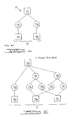
- Figure 1 shows a prior art component representation
- Figure 2 is a representation of a product data model in accordance with a preferred embodiment of the present invention.
- Figure 3A illustrates an example of one way in which an applicability scheme may be applied to the present invention to determine the components used on a given configuration
- Figure 3B shows the projection of unique configurations from the original multivariant reusable assembly graph
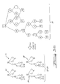
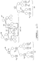
- Figure 4 illustrates a generalized occurrence tree
- Figure 5A illustrates the association of information with a part occurrence, where such information is relevant only to a subset of its total applicability range
- Figure 5B further illustrates subject-matter of Figure 5A
- Figure 6A illustrates a logical occurrence tree and a unique occurrence tree
- Figure 6B further illustrates the logical occurrence tree and the unique occurrence tree
- Figure 7 shows an example product data model in which a subassembly is relatively displaced on one configuration versus another
- Figure 8 shows the mechanism of CAD interface capture and PDM integration
- Figure 9 shows an illustration of a mapping between two domains: 1. engineering, geometric CAD, and 2. manufacturing assembly sequence;
- Figure 10 shows occurrence trees for mapping between the two design domains.
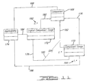
- Figure 11 shows a Unified Modeling Language (UML) representation of the Component, Component Usage and Logical Component Usage object definitions, with a notional representation of an applicability object.
- UML Unified Modeling Language
- a storage structure is required to store and process product related information.
- the most common example of a storage structure is a data structure implemented by a software system. Such a data structure may be embedded or stored in many different and application specific ways.
- Product data stored in the storage structure can be made available to various software tools.
- a product data capture module can read various details of a component like the various assemblies in which the component fits in, the size of the component, and details about component that vary across according to product variant. This data can be shared in many ways. For example across applications like inventory, bill-of-materials and CAD systems.
- the product data captured in the product data model can also be shared across the product family irrespective of the application manipulating the product family, by storage in a database or any other persistent data storage mechanism, like a file.
- the first question deals with what details to store.
- the second question deals with structural issues about how to store the details.
- the product information may be of little utility across applications.
- the present invention uses a hierarchical structure to store the product details. Hierarchical structures allow improved capture and abstraction of product details along with providing flexibility in manipulating captured details. Hence, the present invention provides a hierarchical product data model, which can be shared in multiple ways.
- Figure 1 shows a prior art component representation.
- Two components 10 are included by a parent assembly 12.
- individual parent assemblies 12 in all the figures are labeled as 12 n , where the subscript 'n' indicates a particular instance of the parent assembly 12 in a given embodiment.
- Component usage nodes, 14 1 and 14 2 connect to the parent assembly 12 1 .
- the individual component usage nodes 14 in all of the figures are labeled as 14 n , where the subscript 'n' indicates a particular instance of the component usage node in a given embodiment.
- Child components 16 are associated with the parent assembly 12 through the component usage nodes 14.
- leaf child components 16 in all the figures are labeled 16 n , where the numeric subscript 'n' indicates a particular instance of a child component 16 in a given embodiment.
- a leaf component is defined to contain no child component usages.
- the component usage nodes 14 1 and 14 2 act as links to include child components 16 1 and 16 2 in the parent assembly 12 1 .
- FIG 2 shows a product data model 11 in accordance with a preferred embodiment of the present invention.
- the product data model 10 includes logical component usage nodes 18.
- the nodes 18 associate one parent assembly 12 with one or more component usage nodes 14. Any effectivity or applicability scheme used must preferably ensure that for any one valid assembly configuration of the parent assembly 12 using the logical component usage node 18, there is only one component usage node 14. This is ensured by the logical component usage node 18, which determines which one of the multiple (if any) component usage nodes 14 associated with it becomes part of the given valid assembly configuration of the parent assembly 12.
- Figure 2 shows that a valid assembly configuration having parent assembly 12 2 may have one or a plurality of component usages 14.
- the data model is shown as having three possible component usages 14, including 14 3 and those usages selected by logical component usages 18 1 and 18 2 . It will be appreciated, however, that a greater or lesser plurality of logical component usages 18 can be included to describe a particular product assembly. In the specific example shown in Figure 2, one of the three would be component usage 14 3 ; of the remaining four usages, 14 4 ⁇ 14 7 , one will be selected by 18 1 between 14 4 and 14 5 and the other will be selected by 18 2 between 14 6 and 14 7 .
- Logical component usage identifies that a role for a component usage exists in an assembly and also stores the implementing component usages.
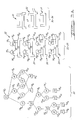
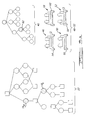
- Figure 3A illustrates the applicability of components to a given configuration.
- the first graph 20 includes three parent component nodes 12 3 -12 5 .
- the component usage nodes 14 and the logical component usage nodes 18 are labeled with applicability attributes that determine whether they apply to a given configuration. For example, let the child component 16 6 represent large a pump and 16 7 represent a small pump.
- the option attribute "O2" is shown inside the component usage nodes 14 10 and 14 12 that are connected to the child component 16 7 representing small pumps. Thus, the presence of the small pump option on an assembly is turned “on” by the presence of the "O2" option attribute.
- the parent assembly 12 can have multiple valid configurations.
- the parent assembly 12 3 could have four valid configurations that are shown as first A1 configuration 22, second A1 configuration 24, third A1 configuration 26 and fourth A1 configuration 28.
- the parent assembly 12 4 shown as embedding a tag "A2,” could have two configurations that are shown as first A2 configuration 30 and second A2 configuration 32.
- the parent assembly 12 5 shown as embedding a tag "A3" has only one configuration that is shown as first A3 configuration 34.
- the first A1 configuration 22 shows an arrangement and a view of the child components 16 6 - 16 11 .
- the second A1 configuration 24, third A1 configuration 26 and fourth A1 configuration 28 are shown as including arrangements and views of the child components 16 6 - 16 11 .
- the invention enables capturing of design sharing between product configurations using a data model.
- the four configurations i.e., the first A1 configuration 22, second A1 configuration 24, third A1 configuration 26 and fourth A1 configuration 28 could have different and unrelated part-usage objects for each assembly configuration.
- common or similar parts are identically numbered across configurations.
- any suitable scheme of applicability can be implemented within the scope of the invention.
- the present invention is not limited by a particular manner of implementing an applicability scheme.
- an explicit applicability attribute could be associated with each of the usage nodes specifying which configurations include each particular usage node.
- option attributes can be associated with the usage nodes and their applicability determined by an option expression developed for each product configuration.
- a versioning scheme could be implemented where different versions of a given part include different version of the usage nodes contained within them, sharing those held in common. A combination of effectivity and versioning could then enable two configurations of an assembly to be applicable within one single product configuration.
- Figure 3B shows the projection of configurations, which could be used to provide single variant views, from the original multi-variant reusable assembly graph.
- the four configurations i.e., the first A1 configuration 22, second A1 configuration 24, third A1 configuration 26 and fourth A1 configuration 28, can each be projected in a view so that they appear as simple assembly definitions, each describing one assembly configuration.
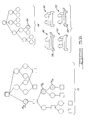
- Figure 4 illustrates a generalized occurrence tree, which are always associated with one particular component.
- the generalized occurrence tree 40 represents the assembly level component 38. Nodes in the occurrence tree correspond to top-to-bottom paths that run from the root of the assembly tree to a usage or to logical usage below the that root assembly.
- the path 36 runs from the root assembly part 38, through usage node 14 8 and to the usage node 14 9 .
- the occurrence nodes of this occurrence tree also correspond to specific parts that would occurrence if a valid configuration of assembly 38 were created. Of course, not all nodes would occur in all product configurations.
- a simple occurrence tree corresponding to each valid product configuration can be built by applying a projection operation on the generalized occurrence tree 40.
- the logical component usage 18 6 is reflected in the occurrence tree 40 as a logical occurrence node 62.
- the logical occurrence node 62 represents the fact that exactly one of either first base 58 or second base 60 is required for constructing any of the assemblies 46-52.
- component usage node 14 19 is reflected in a component usage occurrence node 64.
- the component usage occurrence node 64 represents the fact that the first base 58 is required to construct either the assembly 46 or the assembly 52. So, if information must be associated with the base 58 in assembly 46 but not in assembly 52, some applicability limitations would have to be applied to the data when it was associated with node 64.
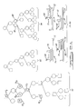
- Figure 6A illustrates a logical occurrence tree and a unique tree.
- a common instance in product design is change of design due to relocation of a subset of the design to a different position with respect to the overall product's coordinate system. For example, a variant longer than the original is created by inserting plugs into a fuselage of a commercial aircraft.
- the invention facilitates easy representation selection and management of variants as illustrated below.
- Second product data model 66 consists of parent assembly 12 6 with an inside label "A8", and another parent assembly 12 7 with an inside label "A7".
- a common flange bracket 68 is represented by child component 16 13 and is attached to the upper left member of sub-assembly 70, represented by the parent assembly 12 7 .
- Sub-assembly 70 is itself attached to a large structural member 72, which is represented by the child component 16 12 . Location of attachment of the sub-assembly 70 to the large structural member 72 differs and hence creates variants.
- first A8 configuration 74 and second A8 configuration 76 show one point of attachment of the sub-assembly 70 to the large structural member 72, while the other point of attachment is shown by the two variants shown as third A8 configuration 78 and fourth A8 configuration 80. All four variants are forms of the parent assembly 12 6 .
- a logical occurrence tree 82 and a unique tree 84 are related to the second graph 66.
- the unique tree 84 is a generalized occurrence tree (as illustrated by Figure 4).
- the component usage nodes 14 19 and 14 20 represent the two usages, which are shown as separate branches in the unique tree 84.
- the branch under the third occurrence node 86 represents the first A8 configuration 74 and the second A8 configuration 76 where the sub-assembly 70 is aligned to the left of large structural member 72.
- another branch under the fourth occurrence node 88 represents the third A8 configuration 78 and the fourth A8 configuration 80 where the sub-assembly 70 is aligned to the right of large structural member 72.
- additional information needs to be appended to fourth occurrence node 88.
- the logical occurrence tree 84 has two branches representing two locations of the sub-assembly 70. The two branches are shown under the fifth logical occurrence node 90 in the logical occurrence tree 84. This arrangement is reflected in the second graph 66 in the role of logical component usage 18 7 that selects either of component usage nodes 14 19 or 14 20 representing the two usages of the parent assembly 12 7 .
- Figure 7 shows the relative representations of the flange bracket 68. If some information needs to be associated with the presence of the flange bracket 68 in all four configurations, i.e., first A8 configuration 74, second A8 configuration 76, third A8 configuration 78 and fourth A8 configuration 80, it is achieved by associating such information with sixth occurrence node 92.
- the mechanism of a logical occurrence tree 82 requires only the path containing logical component usage 18 7 and component usage node 14 21 to specify the sixth occurrence node 92 in the unique occurrence tree, which indicates the presence of the flange bracket 68 in the aforementioned all four configurations.
- the group 94 covers both paths under component usage nodes 14 19 and 14 20 . The coverage of both paths by the sixth occurrence node 92 is shown by its association with the group 94.
- the present invention is broad enough to cover associated mechanisms.
- Examples of associated mechanisms are interface definition sharing between design variants and mappings between product design domains. These examples will now be discussed in detail.
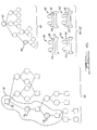
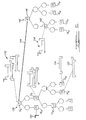
- Figure 8 shows the mechanism of CAD interface capture and PDM integration.
- the four assembly variants are shown as first assembly variant 96, second assembly variant 98, third assembly variant 100 and fourth assembly variant 102.
- each variant would require independent interfaces and interrelationship definitions.
- Conventional CAD assembly systems require one assembly file for each assembly.
- CAD part interface relationships facilitate orientation of parts with respect to each other, and therefore determining part usage locations.
- Each part defines distinct ports and each usage of that part instantiates those ports, which may be connected to instantiated ports of other part usages, with a common parent assembly. Any two such part-usages can be connected by an interface joining their ports.
- the aforementioned four assembly variants 96-102 include four interfaces, i.e. first interface 104, second interface 106, third interface 108 and fourth interface 110.
- part 112 connects to part 116 through the interface 104
- part 114 connects to part 116 through the interface 106
- part 116 connects to part 118 through the interface 108
- part 116 connects to part 120 through the interface 110.
- connection for parts are the same except that part 116 connects to part 122 through the interface 110.
- Each connection of a part usage requires three definitions. The first two definitions are mechanical port definitions on each part usage. The third definition is the relationship between the two that determines the orientation of respective part usages through ports located on each part.
- Logical part usages are permitted to have logical ports.
- a port of a part usage can connect to a logical port of a logical part usage, which indicates that the logical port is implemented by a port of the part usage.
- the logical part usage connection through a logical port will have the same effect, as if a normal part usage port to part usage port connection had been created.
- a candidate product data model 129 includes a first relationship 130, second relationship 132 and third relationship 134, each linking a component usage port to a logical component usage port, as represented by the solid section of these links.
- the dotted section of the links represents alternative implementations of that logical part usage port by particular part usage ports.
- the fourth relationship 136 links two component usage's ports.
- the third product data model graph 138 is a representation of a parent assembly 12 8 with an inside label of "A7".
- the parent assembly 128 has two variants shown as twin variants 142.
- the manufacturing assembly sequence 140 includes a first manufacturing assembly 146 and a second manufacturing assembly 148.
- the parent assembly 12 8 is fully reproduced by the first manufacturing assembly 146 as identified by a relationship link 144.
- the second manufacturing assembly 148 consists of a flange part 150 represented by a child component 16 14 and the assembly 12 10 .
- the child components 16 15 and 16 16 represent a base 152 and a base 154, respectively.
- the second manufacturing assembly 148 is a representation of a part assembly 156.
- the first manufacturing assembly 146 is constructed from a combination of the second manufacturing assembly 148 and either child component 16 15 or 16 16 .
- Figure 10 shows occurrence structures as trees for mapping the engineering CAD assembly domain to the manufacturing assembly sequence domain.
- the CAD tree 158 and the manufacturing tree 160 are used to map relationships between third graph 138 and the manufacturing assembly sequence 140.
- Link 162 shows mapping of child component 16 14 to the manufacturing assembly sequence.
- Link 164 shows mapping of assembly 12 10 using occurrence nodes to the manufacturing assembly sequence.
- Link 166 shows mapping of logical occurrence nodes between the CAD tree 158 and the manufacturing tree 160. Instructions for adding base structural members represented by child components 16 15 and 16 16 can be conveniently shared since there is only one logical mapping between the CAD tree 158 and the manufacturing tree 160.
- the product data model and the associated structures may be preferably stored in computer-associated memories, which may be random-access memories, persistent data-stores, databases or files.
- Figure 11 shows a Unified Modeling Language (UML) representation of the logical component usage extension to the traditional product data model.
- the component object 168, via third relationship 180, can have zero or more logical component usage objects 172 as children.
- the component object 168, via fourth relationship 182 can have zero or more component usage objects 170 as children.
- the logical component usage objects 172, via second relationship 178, may have one or more component usage objects 170 as children.
- the dotted line 190 connecting second relationship 178 to fourth relationship 182 with the symbol ⁇ OR ⁇ in the middle is a constraint relationship.
- a particular component usage object 170 may be connected to either a logical component usage object 172, via relationship 178, or to a component object 168, via relationship 182, but both relationships may not be present simultaneously.
- Each component usage object 170, via first relationship 176, is connected to one and only one child component object 168.
- the applicability object 174 represents a general, notional mechanism for expressing to which particular configuration each logical component usage 172 and component usage 170 is applicable.
- Fifth relationship 184 and sixth relationship 186 carry that applicability information, and seventh relationship 188 connotes the fact that for some applicability schemes the parent assembly configuration can directly control usage applicability. Note that 0..*, 192 means zero or more, and 1..* ,194 means one or more.
- the present invention provides a product data model for representing storing product related information in a memory of an electronic devices, such as a computer.
- the product data model is flexible and versatile to allow sharing of product information within product families and applications.
Landscapes
- Engineering & Computer Science (AREA)
- Physics & Mathematics (AREA)
- Theoretical Computer Science (AREA)
- Computer Hardware Design (AREA)
- Evolutionary Computation (AREA)
- Geometry (AREA)
- General Engineering & Computer Science (AREA)
- General Physics & Mathematics (AREA)
- Management, Administration, Business Operations System, And Electronic Commerce (AREA)
- Information Retrieval, Db Structures And Fs Structures Therefor (AREA)
Abstract
Description
- The present invention relates to data architectures, and more particularly to product information related data architectures that can be used to share product information across product families.
- Increasingly, products are designed using computer aided design (CAD) systems and then manufactured in computer aided manufacturing (CAM) environments. Large engineering projects and complex product designs have increased the need for computer based product related information like CAD designs, CAM instructions and assembly interrelationships. Thus, product designs and related data are being collated on a large scale for storage and processing on computer systems.
- A product family consists of products sharing certain common characteristics. For example, all components in a product family used in an aircraft pumping system may share a common "hydraulic system design". This doesn't mean, however, that all products in the family share the same hydraulic components. The aircraft size determines the individual hydraulic component characteristics of the pumping system, e.g., pump capacity, and the characteristics of its associated components may change, e.g., tubing routes. But the overall hydraulic architecture of the aircraft pumping system remains the same. It is important that a virtual product modeling system be capable of operating on the product "family" as a whole unit.
- Ideally, with a large number of products being designed using CAD systems, virtual product modeling should be easily possible. Virtual product modeling can expedite the design process for a family of products sharing an overall product architecture. However, conventional computer systems are unable to capture a critical fraction of the product data for a family of products necessary to perform virtual product modeling. A required degree of flexibility in a virtual product modeling process for modeling a family of products is not feasible with conventional computer systems. Hence, there is a need for a system capable of capturing a critical reusable quantum of product data for a family of products making flexible virtual product modeling feasible.
- Customizing a given product from a product family also presents limitations to the designer. A designer can customize a product selected from a product family, which includes many product variants. Manufacturers typically face logistical problems in tracking the information about variants. Typical problems involve tracking which parts are contained in a given variant, determining what technical data is applicable to a given variant, determining how the technical data maps on to a manufacturing plan, and how does a given manufacturing plan account for all the parts in a given engineering design. At present, a designer reconstructs relationships between product design domains either mentally or with some minimal computer support. Manual tracking of such relationships incurs high costs and is prone to errors. Thus, there exists a need for a computer-based system to effectively manage relationships between product design domains.
- Methods for defining and managing the relationship of variants to the product family exist. One such method is termed "the effectivity method." Traditional effectivity defines which parts go into each end product configuration. Presently, the trend in the industry is less and less use of traditional effectivity. Reduced use of effectivity means diminishing the knowledge about what is common among different product desians. Thus. there is a need to capture the knowledge about common characteristics of differing product designs.
- When a change is made to a particular product assembly, manufacturing planners get an entirely new assembly definition instead of just the specific changes to that particular product assembly. Manufacturing planners then have to perform significant manual labor to discover the specific minor changes and existing commonality between old and new assembly definitions. This leads to avoidable extra cost in manufacturing planning.
- As the industry increasingly uses CAD designs for modeling products, there will be a need to harmonize CAD designs for a product family having numerous variants. Typical CAD systems can model product assembly structure as part of a three dimensional CAD design for a single variant. Such CAD systems cannot share assembly-level structure among several assembly variants. Thus, designers are forced to maintain multiple and independent CAD designs for variants. Multiplicity of variant designs creates an undesirable situation where there are many copies of engineering and bill-of-materials assembly definitions that are similar, but have unique copies of product structure definitions. Thus, there is a need to eliminate multiple and independent drawings, CAD data and product structure for variants.
- The present invention relates to a hierarchical product data model for storing product data in a memory associated with a computer, and in a persistent storage database, capable of bringing the product data model into computer memory for use by designers. The part used-on assembly information has an important role in product information. The product data model facilitates sharing of product information within a product family.
- The traditional Product Data Model may derived from this model by deleting the Logical Component Usage object and
relationships 2, 3, 5 and the {OR} constraint represented by the dotted line. - A parent assembly holds information for associating the component with the parent assembly. Component-usages holds information relating to usages of the component and connecting a child part to its parent assembly. Logical component-usages hold information relating to logical usages of components and connect child component usages to their parent assembly. The parent assembly, component-usage, and logical component-usage are hierarchically interconnected. The product data model that is the subject of this invention consists of an interrelated set of components, component-usages and logical component usages. The invention is independent of any effectivity or applicability scheme, but can accommodate multiple types of such schemes.
- A generalized occurrence structure represents paths through such a product data model of an assembly. A simple occurrence structure forms a configuration specific tree, which can be projected from the generalized occurrence structure, and can be used to support tools that visualize and edit individual product configurations.
- Further areas of applicability of the present invention will become apparent from the detailed description provided hereinafter. It should be understood that the detailed description and specific examples, while indicating the preferred embodiment of the invention, are intended for purposes of illustration only and are not intended to limit the scope of the invention.
- The present invention will be more fully articulated by the detailed description and the accompanying drawings, wherein:
- Figure 1 shows a prior art component representation;
- Figure 2 is a representation of a product data model in accordance with a preferred embodiment of the present invention;
- Figure 3A illustrates an example of one way in which an applicability scheme may be applied to the present invention to determine the components used on a given configuration;
- Figure 3B shows the projection of unique configurations from the original multivariant reusable assembly graph;
- Figure 4 illustrates a generalized occurrence tree;
- Figure 5A illustrates the association of information with a part occurrence, where such information is relevant only to a subset of its total applicability range;
- Figure 5B further illustrates subject-matter of Figure 5A;
- Figure 6A illustrates a logical occurrence tree and a unique occurrence tree;
- Figure 6B further illustrates the logical occurrence tree and the unique occurrence tree;
- Figure 7 shows an example product data model in which a subassembly is relatively displaced on one configuration versus another;
- Figure 8 shows the mechanism of CAD interface capture and PDM integration;
- Figure 9 shows an illustration of a mapping between two domains: 1. engineering, geometric CAD, and 2. manufacturing assembly sequence;
- Figure 10 shows occurrence trees for mapping between the two design domains.
- Figure 11 shows a Unified Modeling Language (UML) representation of the Component, Component Usage and Logical Component Usage object definitions, with a notional representation of an applicability object.
- The following description of the preferred embodiment(s) is merely exemplary in nature and is in no way intended to limit the invention, its application, or uses.
- The description of the invention is merely exemplary in nature and, thus, variations that do not depart from the gist of the invention are intended to be within the scope of the invention. Such variations are not to be regarded as a departure from the spirit and scope of the invention.
- A storage structure is required to store and process product related information. The most common example of a storage structure is a data structure implemented by a software system. Such a data structure may be embedded or stored in many different and application specific ways. Product data stored in the storage structure can be made available to various software tools. For example, a product data capture module can read various details of a component like the various assemblies in which the component fits in, the size of the component, and details about component that vary across according to product variant. This data can be shared in many ways. For example across applications like inventory, bill-of-materials and CAD systems. The product data captured in the product data model can also be shared across the product family irrespective of the application manipulating the product family, by storage in a database or any other persistent data storage mechanism, like a file.
- Two crucial questions, among others, arise in the design of a product data model. The first question deals with what details to store. The second question deals with structural issues about how to store the details. When the optimum types of details are not stored, the product information may be of little utility across applications. The present invention uses a hierarchical structure to store the product details. Hierarchical structures allow improved capture and abstraction of product details along with providing flexibility in manipulating captured details. Hence, the present invention provides a hierarchical product data model, which can be shared in multiple ways.
- Figure 1 shows a prior art component representation. Two
components 10 are included by aparent assembly 12. For explanatory purposes,individual parent assemblies 12 in all the figures are labeled as 12n, where the subscript 'n' indicates a particular instance of theparent assembly 12 in a given embodiment. Component usage nodes, 141 and 142, connect to theparent assembly 121. The individual component usage nodes 14 in all of the figures are labeled as 14n, where the subscript 'n' indicates a particular instance of the component usage node in a given embodiment. Child components 16 are associated with theparent assembly 12 through the component usage nodes 14. Individual leaf child components 16 in all the figures are labeled 16n, where the numeric subscript 'n' indicates a particular instance of a child component 16 in a given embodiment. A leaf component is defined to contain no child component usages. In the context of figure 1, the component usage nodes 141 and 142 act as links to include child components 161 and 162 in theparent assembly 121. - Figure 2 shows a
product data model 11 in accordance with a preferred embodiment of the present invention. Theproduct data model 10 includes logicalcomponent usage nodes 18. Thenodes 18 associate oneparent assembly 12 with one or more component usage nodes 14. Any effectivity or applicability scheme used must preferably ensure that for any one valid assembly configuration of theparent assembly 12 using the logicalcomponent usage node 18, there is only one component usage node 14. This is ensured by the logicalcomponent usage node 18, which determines which one of the multiple (if any) component usage nodes 14 associated with it becomes part of the given valid assembly configuration of theparent assembly 12. Figure 2 shows that a valid assembly configuration havingparent assembly 122 may have one or a plurality of component usages 14. In this illustration, the data model is shown as having three possible component usages 14, including 143 and those usages selected bylogical component usages logical component usages 18 can be included to describe a particular product assembly. In the specific example shown in Figure 2, one of the three would be component usage 143; of the remaining four usages, 144 → 147, one will be selected by 181 between 144 and 145 and the other will be selected by 182 between 146 and 147. Logical component usage identifies that a role for a component usage exists in an assembly and also stores the implementing component usages. - Figure 3A illustrates the applicability of components to a given configuration. The
first graph 20 includes three parent component nodes 123-125. The component usage nodes 14 and the logicalcomponent usage nodes 18 are labeled with applicability attributes that determine whether they apply to a given configuration. For example, let the child component 166 represent large a pump and 167 represent a small pump. The option attribute "O2" is shown inside the component usage nodes 1410 and 1412 that are connected to the child component 167 representing small pumps. Thus, the presence of the small pump option on an assembly is turned "on" by the presence of the "O2" option attribute. Similarly, the presence of the large pump option is turned "on" by the presence of the "O1" option attribute, shown inside the component usage nodes 149 and 1411. It is assumed that the options "O1" and "O2" are mutually exclusive. In the same way, option attribute "O3" shown inside the component usage node 1416 is used to select child component 1610. Likewise, option attribute "O4" shown inside the component usage node 1417 is used to select child component 1611. - The
parent assembly 12 can have multiple valid configurations. For example, theparent assembly 123 could have four valid configurations that are shown asfirst A1 configuration 22,second A1 configuration 24,third A1 configuration 26 andfourth A1 configuration 28. Similarly, theparent assembly 124, shown as embedding a tag "A2," could have two configurations that are shown asfirst A2 configuration 30 andsecond A2 configuration 32. Theparent assembly 125 shown as embedding a tag "A3" has only one configuration that is shown as first A3 configuration 34. - The
first A1 configuration 22 shows an arrangement and a view of the child components 166 - 1611. Similarly, thesecond A1 configuration 24,third A1 configuration 26 andfourth A1 configuration 28 are shown as including arrangements and views of the child components 166 - 1611. - The invention enables capturing of design sharing between product configurations using a data model. For example, the four configurations, i.e., the
first A1 configuration 22,second A1 configuration 24,third A1 configuration 26 andfourth A1 configuration 28 could have different and unrelated part-usage objects for each assembly configuration. However, due to design sharing, common or similar parts are identically numbered across configurations. - Any suitable scheme of applicability can be implemented within the scope of the invention. The present invention is not limited by a particular manner of implementing an applicability scheme. For example, an explicit applicability attribute could be associated with each of the usage nodes specifying which configurations include each particular usage node. Alternatively, option attributes can be associated with the usage nodes and their applicability determined by an option expression developed for each product configuration. Further, a versioning scheme could be implemented where different versions of a given part include different version of the usage nodes contained within them, sharing those held in common. A combination of effectivity and versioning could then enable two configurations of an assembly to be applicable within one single product configuration.
- Figure 3B shows the projection of configurations, which could be used to provide single variant views, from the original multi-variant reusable assembly graph. Using the
first graph 20, the four configurations, i.e., thefirst A1 configuration 22,second A1 configuration 24,third A1 configuration 26 andfourth A1 configuration 28, can each be projected in a view so that they appear as simple assembly definitions, each describing one assembly configuration. - Figure 4 illustrates a generalized occurrence tree, which are always associated with one particular component. For example, the
generalized occurrence tree 40 represents theassembly level component 38. Nodes in the occurrence tree correspond to top-to-bottom paths that run from the root of the assembly tree to a usage or to logical usage below the that root assembly. For example, thepath 36 runs from theroot assembly part 38, through usage node 148 and to the usage node 149. The occurrence nodes of this occurrence tree also correspond to specific parts that would occurrence if a valid configuration ofassembly 38 were created. Of course, not all nodes would occur in all product configurations. A simple occurrence tree corresponding to each valid product configuration can be built by applying a projection operation on thegeneralized occurrence tree 40. - Referring to Figure 5A, in certain cases, there will be a need to associate information with a part occurrence, but where such information is relevant only to a sub-set of its total applicability range. Such information must be qualified with relevant applicability statements. For example, the
logical component usage 186 is reflected in theoccurrence tree 40 as alogical occurrence node 62. Thelogical occurrence node 62 represents the fact that exactly one of eitherfirst base 58 orsecond base 60 is required for constructing any of the assemblies 46-52. - Referring to figure 5B, the role of component usage node 1419 is reflected in a component
usage occurrence node 64. The componentusage occurrence node 64 represents the fact that thefirst base 58 is required to construct either theassembly 46 or theassembly 52. So, if information must be associated with the base 58 inassembly 46 but not inassembly 52, some applicability limitations would have to be applied to the data when it was associated withnode 64. - Figure 6A illustrates a logical occurrence tree and a unique tree. A common instance in product design is change of design due to relocation of a subset of the design to a different position with respect to the overall product's coordinate system. For example, a variant longer than the original is created by inserting plugs into a fuselage of a commercial aircraft. The invention facilitates easy representation selection and management of variants as illustrated below.
- Second
product data model 66 consists ofparent assembly 126 with an inside label "A8", and anotherparent assembly 127 with an inside label "A7". Acommon flange bracket 68 is represented by child component 1613 and is attached to the upper left member ofsub-assembly 70, represented by theparent assembly 127.Sub-assembly 70 is itself attached to a largestructural member 72, which is represented by the child component 1612. Location of attachment of the sub-assembly 70 to the largestructural member 72 differs and hence creates variants. Two variants shown asfirst A8 configuration 74 andsecond A8 configuration 76 show one point of attachment of the sub-assembly 70 to the largestructural member 72, while the other point of attachment is shown by the two variants shown asthird A8 configuration 78 andfourth A8 configuration 80. All four variants are forms of theparent assembly 126. - A
logical occurrence tree 82 and aunique tree 84 are related to thesecond graph 66. Theunique tree 84 is a generalized occurrence tree (as illustrated by Figure 4). The component usage nodes 1419 and 1420 represent the two usages, which are shown as separate branches in theunique tree 84. The branch under thethird occurrence node 86 represents thefirst A8 configuration 74 and thesecond A8 configuration 76 where the sub-assembly 70 is aligned to the left of largestructural member 72. Similarly, another branch under thefourth occurrence node 88 represents thethird A8 configuration 78 and thefourth A8 configuration 80 where the sub-assembly 70 is aligned to the right of largestructural member 72. To refer to a particular configuration of thethird A8 configuration 78 and thefourth A8 configuration 80, additional information needs to be appended tofourth occurrence node 88. - Referring to Figure 6B, the
logical occurrence tree 84 has two branches representing two locations of thesub-assembly 70. The two branches are shown under the fifthlogical occurrence node 90 in thelogical occurrence tree 84. This arrangement is reflected in thesecond graph 66 in the role oflogical component usage 187 that selects either of component usage nodes 1419 or 1420 representing the two usages of theparent assembly 127. - Figure 7 shows the relative representations of the
flange bracket 68. If some information needs to be associated with the presence of theflange bracket 68 in all four configurations, i.e.,first A8 configuration 74,second A8 configuration 76,third A8 configuration 78 andfourth A8 configuration 80, it is achieved by associating such information withsixth occurrence node 92. The mechanism of alogical occurrence tree 82 requires only the path containinglogical component usage 187 and component usage node 1421 to specify thesixth occurrence node 92 in the unique occurrence tree, which indicates the presence of theflange bracket 68 in the aforementioned all four configurations. Thegroup 94 covers both paths under component usage nodes 1419 and 1420. The coverage of both paths by thesixth occurrence node 92 is shown by its association with thegroup 94. - The present invention is broad enough to cover associated mechanisms. Examples of associated mechanisms are interface definition sharing between design variants and mappings between product design domains. These examples will now be discussed in detail.
- Figure 8 shows the mechanism of CAD interface capture and PDM integration. The four assembly variants are shown as
first assembly variant 96,second assembly variant 98,third assembly variant 100 andfourth assembly variant 102. In a conventional CAD assembly management system, each variant would require independent interfaces and interrelationship definitions. Conventional CAD assembly systems require one assembly file for each assembly. CAD part interface relationships facilitate orientation of parts with respect to each other, and therefore determining part usage locations. - Each part defines distinct ports and each usage of that part instantiates those ports, which may be connected to instantiated ports of other part usages, with a common parent assembly. Any two such part-usages can be connected by an interface joining their ports. The aforementioned four assembly variants 96-102 include four interfaces, i.e.
first interface 104,second interface 106,third interface 108 andfourth interface 110. Inassembly variants part 112 connects to part 116 through theinterface 104,part 114 connects to part 116 through theinterface 106,part 116 connects to part 118 through theinterface 108, andpart 116 connects to part 120 through theinterface 110. Inassembly variants part 116 connects to part 122 through theinterface 110. Each connection of a part usage requires three definitions. The first two definitions are mechanical port definitions on each part usage. The third definition is the relationship between the two that determines the orientation of respective part usages through ports located on each part. - Logical part usages are permitted to have logical ports. A port of a part usage can connect to a logical port of a logical part usage, which indicates that the logical port is implemented by a port of the part usage. For each assembly configuration, the logical part usage connection through a logical port will have the same effect, as if a normal part usage port to part usage port connection had been created.
- A candidate
product data model 129 includes afirst relationship 130,second relationship 132 and third relationship 134, each linking a component usage port to a logical component usage port, as represented by the solid section of these links. The dotted section of the links represents alternative implementations of that logical part usage port by particular part usage ports. Thefourth relationship 136 links two component usage's ports. - Another application of the present invention is to capture mapping between the engineering CAD assembly design domain and the manufacturing assembly sequence design domain. Figure 9 shows an illustration of such a mapping. The third product
data model graph 138 is a representation of aparent assembly 128 with an inside label of "A7". The parent assembly 128 has two variants shown astwin variants 142. Themanufacturing assembly sequence 140 includes afirst manufacturing assembly 146 and asecond manufacturing assembly 148. Theparent assembly 128 is fully reproduced by thefirst manufacturing assembly 146 as identified by arelationship link 144. Thesecond manufacturing assembly 148 consists of aflange part 150 represented by a child component 1614 and theassembly 1210. The child components 1615 and 1616 represent abase 152 and abase 154, respectively. Thesecond manufacturing assembly 148 is a representation of apart assembly 156. Thus, thefirst manufacturing assembly 146 is constructed from a combination of thesecond manufacturing assembly 148 and either child component 1615 or 1616. - Figure 10 shows occurrence structures as trees for mapping the engineering CAD assembly domain to the manufacturing assembly sequence domain. The
CAD tree 158 and themanufacturing tree 160 are used to map relationships betweenthird graph 138 and themanufacturing assembly sequence 140.Link 162 shows mapping of child component 1614 to the manufacturing assembly sequence.Link 164 shows mapping ofassembly 1210 using occurrence nodes to the manufacturing assembly sequence.Link 166 shows mapping of logical occurrence nodes between theCAD tree 158 and themanufacturing tree 160. Instructions for adding base structural members represented by child components 1615 and 1616 can be conveniently shared since there is only one logical mapping between theCAD tree 158 and themanufacturing tree 160. - The product data model and the associated structures may be preferably stored in computer-associated memories, which may be random-access memories, persistent data-stores, databases or files.
- Figure 11 shows a Unified Modeling Language (UML) representation of the logical component usage extension to the traditional product data model. The
component object 168, viathird relationship 180, can have zero or more logical component usage objects 172 as children. Similarly, thecomponent object 168, viafourth relationship 182, can have zero or more component usage objects 170 as children. The logical component usage objects 172, viasecond relationship 178, may have one or more component usage objects 170 as children. The dottedline 190 connectingsecond relationship 178 tofourth relationship 182 with the symbol {OR} in the middle is a constraint relationship. This means that a particularcomponent usage object 170 may be connected to either a logicalcomponent usage object 172, viarelationship 178, or to acomponent object 168, viarelationship 182, but both relationships may not be present simultaneously. Eachcomponent usage object 170, viafirst relationship 176, is connected to one and only onechild component object 168. Theapplicability object 174 represents a general, notional mechanism for expressing to which particular configuration eachlogical component usage 172 andcomponent usage 170 is applicable.Fifth relationship 184 andsixth relationship 186 carry that applicability information, andseventh relationship 188 connotes the fact that for some applicability schemes the parent assembly configuration can directly control usage applicability. Note that 0..*, 192 means zero or more, and 1..* ,194 means one or more. - The present invention provides a product data model for representing storing product related information in a memory of an electronic devices, such as a computer. The product data model is flexible and versatile to allow sharing of product information within product families and applications.
- The description of the invention is merely exemplary in nature and, thus, variations that do not depart from the gist of the invention are intended to be within the scope of the invention. Such variations are not to be regarded as a departure from the spirit and scope of the invention.
Claims (25)
- A product data-model stored in a memory associated with a computer, said product data-model representing product information about at least one component that is a constituent of at least one parent assembly, comprising:a parent assembly holding information for associating the component with the parent assembly;a plurality of component-usages for holding information relating to usages of the component, said component-usages being operatively connected to the parent assembly;a plurality of logical component-usages for holding information relating to logical usages of the component, said component-usages being operatively connected to said component-usages; andsaid parent assembly, said component-usages and said logical component-usages being hierarchically interconnected.
- The product data-model of claim 1, wherein
said logical component-usage is utilized for selecting one from the component-usages connected to it. - The product data-model of claim 1, wherein
said logical component-usages are used to identify the existence of a role for said component-usages in an assembly configuration. - The product data-model of claim 1, wherein said component-usages are utilized for selecting one component usage to be included in a product configuration.
- The product data-model of claim 1, wherein said component-usages represent usages of a plurality of items and logical component-usages represent logical usages of said items.
- The product data-model of claim 1, wherein said memory is selected from a group consisting of random-access memories, data-stores, databases, persistent data stores and files.
- A representation structure stored in a memory and representing a plurality of assemblies, wherein each said assembly includes a plurality of constituent components, the representation structure comprising:at least one product data-models, each of said product data-models representing at least one said constituent component;said product data-models being hierarchically interconnected for representing each of said assemblies; andeach said product data-model including a parent assembly for holding information for associating each said constituent component to at least one of said assemblies.
- The representation structure of claim 7, wherein said product data-model further comprises:a plurality of component-usages for holding information relating to usages of said constituent components, said component-usages being operatively connected to said parent assembly.
- The representation structure of claim 8, wherein said product data-model further comprises:a plurality of logical component-usages for holding information relating to logical usages of said constituent components, said logical component-usages being operatively connected to said component-usages; andsaid parent assembly, said component-usages and said logical component-usages being hierarchically interconnected.
- The representation structure of claim 9, further comprising:a plurality of configuration projections derived from said representation structure.
- The representation structure of claim 7 wherein said structure comprises a top-to-bottom, directed, acyclic graph structure for storing said representation structure in said memory.
- An occurrence structure group stored in a memory and representing assembly configurations, comprising:a plurality of generalized occurrence structures including:a plurality of occurrence nodes corresponding to and representing a plurality of paths in a representation of a product data-model; anda plurality of logical occurrence nodes hierarchically interconnected with said occurrences nodes, each of said logical occurrence nodes utilized for selecting one from at least one associated said occurrence nodes.
- The occurrence structure group of claim 12, wherein said generalized occurrence structure comprises a tree-like structure.
- The occurrence structure group of claim 12, further comprising:a plurality of simplified occurrence structures derived from said generalized occurrence structure, said simplified occurrence structures representing a valid configuration of an assembly.
- The occurrence structure group of claim 14, wherein a single one of said simplified occurrence structures comprises a tree structure.
- The occurrence structure group of claim 12, further comprising:a plurality of information units associated with a selection of said occurrence nodes.
- The occurrence structure group of claim 12, further comprising:a logical occurrence structure stored in a memory and representing logically similar information, comprising:a plurality of logical occurrence nodes for representing logically similar information among a plurality of configurations.
- A method for representing product data in a memory, comprising:constructing a plurality of assemblies;constructing a plurality of component-usages for associating a plurality of components with at least one parent assembly, said parent assembly having said components as constituents, said component-usages connecting to said parent assemblies;constructing a plurality of logical component-usages associated with said component-usages, said logical component-usages connecting to component-usages; andconstructing hierarchically interconnected relationships between said component-usages and said logical component-usages to form a product data model.
- The method of claim 18, further comprising:capturing product data for a product family;storing captured product data for said product family in said product data-model; andmodeling computationally said product family using said product data-model.
- The method of claim 19, further comprising:capturing product data for an assembly having at least one variant;storing captured product data for said variants in said product data-model; andconstructing a reduced duplication of computer-aided-design data to capture a number of design variations within a product family using said product data-model.
- A method for representing assembly configurations using a generalized occurrence structure stored in a memory, comprising:(a) constructing a plurality of occurrence nodes corresponding to paths in a representation of a product data-model comprising a hierarchically interconnected parent assembly, a plurality of component-usages, and a plurality of logical component-usages;(b) constructing a plurality of logical occurrence nodes associated with a plurality of said occurrences nodes; and(c) storing product data in said occurrence nodes.
- The method of claim 21, step (a) further comprising:associating a plurality of part-interfaces with said occurrence nodes;associating a plurality of part usages with a plurality of logical occurrence nodes depending upon logical relationships between said part-usages; andforming a mapping of a plurality of computer-aided-designs of said parts with said product data-model.
- The method of claim 21, wherein said step (a) further comprises:forming a mapping of at least one manufacturing assembly sequence to at least one computer-aided-design that is stored in said product data model, said manufacturing assembly sequence comprising a plurality of manufacturing assemblies which include a plurality of components and a plurality of assemblies.
- The method of claim 21, wherein said step (a) further comprises:forming a mapping from of a subset of the product data model, for any design domain of a given product family, to a subset of any other design domain representing another design aspect of the same product family.
- The method of claim 21, wherein said step (a) further comprises:forming a mapping from a whole of the product data model, for any design domain of a given product family, and part or all of any other design domain representing another aspect of the design of the same product family.
Applications Claiming Priority (2)
| Application Number | Priority Date | Filing Date | Title |
|---|---|---|---|
| US128922 | 1998-08-04 | ||
| US10/128,922 US7085776B2 (en) | 2002-04-24 | 2002-04-24 | Logical hierarchical data model for sharing product information across product families |
Publications (2)
| Publication Number | Publication Date |
|---|---|
| EP1357486A2 true EP1357486A2 (en) | 2003-10-29 |
| EP1357486A3 EP1357486A3 (en) | 2005-06-22 |
Family
ID=28790965
Family Applications (1)
| Application Number | Title | Priority Date | Filing Date |
|---|---|---|---|
| EP03076109A Ceased EP1357486A3 (en) | 2002-04-24 | 2003-04-14 | Logical hierarchical data model for sharing product information across product families |
Country Status (2)
| Country | Link |
|---|---|
| US (1) | US7085776B2 (en) |
| EP (1) | EP1357486A3 (en) |
Cited By (7)
| Publication number | Priority date | Publication date | Assignee | Title |
|---|---|---|---|---|
| EP1447760A3 (en) * | 2003-01-21 | 2005-06-29 | The Boeing Company | Apparatus and method for managing multivariant assembly data models |
| US7085776B2 (en) | 2002-04-24 | 2006-08-01 | The Boeing Company | Logical hierarchical data model for sharing product information across product families |
| US7447833B2 (en) | 2005-06-29 | 2008-11-04 | Emc Corporation | Techniques for providing communications in a data storage system using a single IC for both storage device communications and peer-to-peer communications |
| WO2008095574A3 (en) * | 2007-02-07 | 2009-04-09 | Sew Eurodrive Gmbh & Co | Use of graphs, method and computer system for creating a construction drawing, method for manufacturing a product, and use of said method |
| JP2017199344A (en) * | 2016-02-12 | 2017-11-02 | ザ・ボーイング・カンパニーThe Boeing Company | Model for managing changes in product structure of product |
| EP2698734A3 (en) * | 2012-08-14 | 2017-12-06 | The Boeing Company | Model for managing variations in a product structure for a product |
| US10140387B2 (en) | 2005-08-02 | 2018-11-27 | The Boeing Company | Model for managing variations in a product structure for a product |
Families Citing this family (24)
| Publication number | Priority date | Publication date | Assignee | Title |
|---|---|---|---|---|
| US7225038B2 (en) * | 2003-09-26 | 2007-05-29 | Sap Ag | Method and system for checking consistency and completeness of selection conditions in a product configuration system |
| US20060020504A1 (en) * | 2004-07-23 | 2006-01-26 | Ugs Corp. | System and method for bill of materials grading |
| US8812965B2 (en) * | 2005-06-01 | 2014-08-19 | Siemens Product Lifecycle Management Software Inc. | Creation and publishing of virtual components |
| US8275799B2 (en) * | 2005-08-02 | 2012-09-25 | The Boeing Company | Methods and apparatus for information modeling |
| US8402007B2 (en) * | 2005-08-02 | 2013-03-19 | The Boeing Company | Methods and apparatus for creating and utilizing templates in connection with information modeling |
| US8224471B2 (en) * | 2005-09-27 | 2012-07-17 | Siemens Product Lifecycle Management Software Inc. | Allocation of multiple product structures |
| JP5001614B2 (en) * | 2006-09-26 | 2012-08-15 | 株式会社日立製作所 | Design change range search method, design change range search device, and design change range search system |
| US7827012B2 (en) * | 2006-12-08 | 2010-11-02 | The Boeing Company | System and method for controlling structural type integration |
| US8014886B2 (en) * | 2008-05-12 | 2011-09-06 | Ford Motor Company | Method and system for generating an assembly configuration |
| US8078443B2 (en) * | 2008-05-12 | 2011-12-13 | Ford Motor Company | Method and system for generating configuration constraints for computer models |
| US8245020B1 (en) * | 2008-05-13 | 2012-08-14 | Selectica, Inc. | Creating a partial instance of component in response to user specifying a value for a dynamic attribute of a selected component |
| US8825450B2 (en) * | 2009-10-22 | 2014-09-02 | Dassault Systemes | Method and system for updating a modeled object in a product lifecycle management system |
| US9268883B2 (en) | 2010-02-26 | 2016-02-23 | The Boeing Company | User interface for presenting information about a product structure for a product |
| US8533237B2 (en) * | 2011-09-23 | 2013-09-10 | Siemens Product Lifecycle Management Software Inc. | Data structure partitioning in product data management systems |
| US8458228B2 (en) * | 2011-09-23 | 2013-06-04 | Siemens Product Lifecycle Management Software Inc. | Occurrence management in product data management systems |
| WO2013110966A1 (en) | 2012-01-27 | 2013-08-01 | Empire Technology Development Llc | Parameterized dynamic model for cloud migration |
| US9123008B2 (en) * | 2012-05-30 | 2015-09-01 | Siemens Product Lifecycle Management Software Inc. | Buildable part pairs in an unconfigured product structure |
| US8849440B2 (en) * | 2012-05-31 | 2014-09-30 | International Business Machines Corporation | Manufacturing control based on a final design structure incorporating both layout and client-specific manufacturing information |
| US8965831B2 (en) | 2012-07-27 | 2015-02-24 | Selectica, Inc. | System, method, and software program product for enabling users to create and use rule patterns to generate custom product-configuration rules |
| US20160125329A1 (en) * | 2014-10-30 | 2016-05-05 | Siemens Product Lifecycle Management Software Inc. | System and method for configuration-managed lifecycle diagrams |
| EP3054404A1 (en) * | 2015-02-04 | 2016-08-10 | Hexagon Technology Center GmbH | Work information modelling |
| US11971865B2 (en) | 2017-09-11 | 2024-04-30 | Bentley Systems, Incorporated | Intelligent model hierarchy for infrastructure modeling |
| CN110096543B (en) * | 2019-05-06 | 2021-07-09 | 软通智慧科技有限公司 | Application data manipulation method, apparatus, server and medium |
| US20220156704A1 (en) * | 2020-11-16 | 2022-05-19 | Ford Global Technologies, Llc | Method and system for transmitting data from manufacturing data originators to target computing systems using defined message schemas |
Family Cites Families (14)
| Publication number | Priority date | Publication date | Assignee | Title |
|---|---|---|---|---|
| US237057A (en) * | 1881-01-25 | sherwood | ||
| US1357486A (en) | 1918-03-29 | 1920-11-02 | Burke Electric Company | Arc-welding system |
| US4591983A (en) | 1984-07-09 | 1986-05-27 | Teknowledge, Inc. | Hierarchical knowledge system |
| US5119307A (en) | 1989-12-22 | 1992-06-02 | General Electric Company | Method and system for automated bill-of-material generation |
| US5311424A (en) | 1991-06-28 | 1994-05-10 | International Business Machines Corporation | Method and system for product configuration definition and tracking |
| JPH05151229A (en) | 1991-06-28 | 1993-06-18 | Internatl Business Mach Corp <Ibm> | Method and system for automatically generating product configurations in a computer-based manufacturing system |
| US6115547A (en) | 1993-03-29 | 2000-09-05 | Trilogy Development Group, Inc. | Flash configuration cache |
| US5434791A (en) | 1993-06-29 | 1995-07-18 | Electronic Data Systems Corporation | Product structure management |
| US5552995A (en) * | 1993-11-24 | 1996-09-03 | The Trustees Of The Stevens Institute Of Technology | Concurrent engineering design tool and method |
| US6223094B1 (en) * | 1998-08-21 | 2001-04-24 | Sap Aktiengesellschaft | Multi-tiered structure for storing and displaying product and process variants |
| US6611725B1 (en) * | 2000-02-03 | 2003-08-26 | Solidworks Corporation | Computer drawing system |
| US7085776B2 (en) | 2002-04-24 | 2006-08-01 | The Boeing Company | Logical hierarchical data model for sharing product information across product families |
| US6944832B2 (en) | 2002-06-20 | 2005-09-13 | The Boeing Company | System design using part roles |
| US7038677B2 (en) | 2003-01-21 | 2006-05-02 | The Boeing Company | Apparatus and method for managing multivariant assembly data models |
-
2002
- 2002-04-24 US US10/128,922 patent/US7085776B2/en not_active Expired - Lifetime
-
2003
- 2003-04-14 EP EP03076109A patent/EP1357486A3/en not_active Ceased
Non-Patent Citations (3)
| Title |
|---|
| GU P ET AL: "Product modelling using step" COMPUTER AIDED DESIGN, ELSEVIER PUBLISHERS BV., BARKING, GB, vol. 27, no. 3, March 1995 (1995-03), pages 163-179, XP004022823 ISSN: 0010-4485 * |
| WONGVASU N ET AL: "Representing the relationship between items in logical bill-of-material to support customers' requests for quotation for make-to-order products" PROCEEDINGS OF THE SPIE, SPIE, BELLINGHAM, VA, US, vol. 4192, 2000, pages 74-85, XP002307659 ISSN: 0277-786X * |
| WONGVASU N ET AL: "Trie representation for expressing the compatibility between items in a logical bill of material structure" PROCEEDINGS OF THE SPIE, SPIE, BELLINGHAM, VA, US, vol. 4565, 2001, pages 84-90, XP002307762 ISSN: 0277-786X * |
Cited By (8)
| Publication number | Priority date | Publication date | Assignee | Title |
|---|---|---|---|---|
| US7085776B2 (en) | 2002-04-24 | 2006-08-01 | The Boeing Company | Logical hierarchical data model for sharing product information across product families |
| EP1447760A3 (en) * | 2003-01-21 | 2005-06-29 | The Boeing Company | Apparatus and method for managing multivariant assembly data models |
| US7038677B2 (en) | 2003-01-21 | 2006-05-02 | The Boeing Company | Apparatus and method for managing multivariant assembly data models |
| US7447833B2 (en) | 2005-06-29 | 2008-11-04 | Emc Corporation | Techniques for providing communications in a data storage system using a single IC for both storage device communications and peer-to-peer communications |
| US10140387B2 (en) | 2005-08-02 | 2018-11-27 | The Boeing Company | Model for managing variations in a product structure for a product |
| WO2008095574A3 (en) * | 2007-02-07 | 2009-04-09 | Sew Eurodrive Gmbh & Co | Use of graphs, method and computer system for creating a construction drawing, method for manufacturing a product, and use of said method |
| EP2698734A3 (en) * | 2012-08-14 | 2017-12-06 | The Boeing Company | Model for managing variations in a product structure for a product |
| JP2017199344A (en) * | 2016-02-12 | 2017-11-02 | ザ・ボーイング・カンパニーThe Boeing Company | Model for managing changes in product structure of product |
Also Published As
| Publication number | Publication date |
|---|---|
| US7085776B2 (en) | 2006-08-01 |
| EP1357486A3 (en) | 2005-06-22 |
| US20030204527A1 (en) | 2003-10-30 |
Similar Documents
| Publication | Publication Date | Title |
|---|---|---|
| US7085776B2 (en) | Logical hierarchical data model for sharing product information across product families | |
| US6944514B1 (en) | Innovation information management model | |
| US9760589B2 (en) | Mechanism for deprecating object oriented data | |
| US8402007B2 (en) | Methods and apparatus for creating and utilizing templates in connection with information modeling | |
| US20020091990A1 (en) | System for software application development and modeling | |
| JPH11510922A (en) | Flash configuration cache | |
| US20120151443A1 (en) | Globally sound and consistent configuration management for distributed datacenter components | |
| US7107280B2 (en) | Method and system for the storage and use of engineering modeling alternatives with unitized data | |
| US20050177545A1 (en) | Method and apparatus for representing and managing service level agreement management data and relationships thereof | |
| JPH0475134A (en) | File managing device | |
| Djebbi et al. | Criteria for comparing requirements variability modeling notations for product lines | |
| US7644370B2 (en) | Method of componentisation of a graphically defined formula | |
| CN116822195A (en) | Bidirectional model conversion method based on SysML v1 and SysML v2 | |
| Liu et al. | Database schema evolution through the specification and maintenance of changes on entities and relationships | |
| US10140387B2 (en) | Model for managing variations in a product structure for a product | |
| US20070255685A1 (en) | Method and system for modelling data | |
| CA2816830C (en) | Model for managing variations in a product structure for a product | |
| WO1999033006A1 (en) | Evolution of object-relational mapping through source code merging | |
| WO2001008007A1 (en) | Method and system of automated generation of program code from an object oriented model | |
| US20050246160A1 (en) | Information generation system for product formation | |
| Poulin | Integrated support for software reuse in computer-aided software engineering (CASE) | |
| Fu | Hierarchical modeling of large-scale systems using relational databases | |
| CN120745018B (en) | System and method for managing types and models of components in BIM software | |
| Rashid et al. | A database evolution taxonomy for object‐oriented databases | |
| Atkinson et al. | Controlling view editability in projection-based modeling environments |
Legal Events
| Date | Code | Title | Description |
|---|---|---|---|
| PUAI | Public reference made under article 153(3) epc to a published international application that has entered the european phase |
Free format text: ORIGINAL CODE: 0009012 |
|
| AK | Designated contracting states |
Kind code of ref document: A2 Designated state(s): AT BE BG CH CY CZ DE DK EE ES FI FR GB GR HU IE IT LI LU MC NL PT RO SE SI SK TR |
|
| AX | Request for extension of the european patent |
Extension state: AL LT LV MK |
|
| PUAL | Search report despatched |
Free format text: ORIGINAL CODE: 0009013 |
|
| AK | Designated contracting states |
Kind code of ref document: A3 Designated state(s): AT BE BG CH CY CZ DE DK EE ES FI FR GB GR HU IE IT LI LU MC NL PT RO SE SI SK TR |
|
| AX | Request for extension of the european patent |
Extension state: AL LT LV MK |
|
| 17P | Request for examination filed |
Effective date: 20050809 |
|
| AKX | Designation fees paid |
Designated state(s): AT BE BG CH CY CZ DE DK EE ES FI FR GB GR HU IE IT LI LU MC NL PT RO SE SI SK TR |
|
| APBK | Appeal reference recorded |
Free format text: ORIGINAL CODE: EPIDOSNREFNE |
|
| APBN | Date of receipt of notice of appeal recorded |
Free format text: ORIGINAL CODE: EPIDOSNNOA2E |
|
| APBR | Date of receipt of statement of grounds of appeal recorded |
Free format text: ORIGINAL CODE: EPIDOSNNOA3E |
|
| APAF | Appeal reference modified |
Free format text: ORIGINAL CODE: EPIDOSCREFNE |
|
| APAF | Appeal reference modified |
Free format text: ORIGINAL CODE: EPIDOSCREFNE |
|
| APBT | Appeal procedure closed |
Free format text: ORIGINAL CODE: EPIDOSNNOA9E |
|
| STAA | Information on the status of an ep patent application or granted ep patent |
Free format text: STATUS: THE APPLICATION HAS BEEN REFUSED |
|
| 18R | Application refused |
Effective date: 20140310 |