EP1357353A2 - Laser level - Google Patents
Laser level Download PDFInfo
- Publication number
- EP1357353A2 EP1357353A2 EP03016849A EP03016849A EP1357353A2 EP 1357353 A2 EP1357353 A2 EP 1357353A2 EP 03016849 A EP03016849 A EP 03016849A EP 03016849 A EP03016849 A EP 03016849A EP 1357353 A2 EP1357353 A2 EP 1357353A2
- Authority
- EP
- European Patent Office
- Prior art keywords
- housing
- laser
- shaft
- disposed
- assembly
- Prior art date
- Legal status (The legal status is an assumption and is not a legal conclusion. Google has not performed a legal analysis and makes no representation as to the accuracy of the status listed.)
- Granted
Links
- 230000001681 protective effect Effects 0.000 claims description 25
- 230000007246 mechanism Effects 0.000 claims description 14
- 238000000034 method Methods 0.000 claims description 6
- 238000010276 construction Methods 0.000 description 8
- 230000036961 partial effect Effects 0.000 description 8
- 239000004033 plastic Substances 0.000 description 8
- 230000005540 biological transmission Effects 0.000 description 6
- 230000004907 flux Effects 0.000 description 6
- 230000033001 locomotion Effects 0.000 description 6
- 229910052782 aluminium Inorganic materials 0.000 description 5
- XAGFODPZIPBFFR-UHFFFAOYSA-N aluminium Chemical compound [Al] XAGFODPZIPBFFR-UHFFFAOYSA-N 0.000 description 5
- 238000005259 measurement Methods 0.000 description 5
- 230000035945 sensitivity Effects 0.000 description 5
- 238000010586 diagram Methods 0.000 description 4
- 239000000463 material Substances 0.000 description 4
- 230000003287 optical effect Effects 0.000 description 4
- 230000002441 reversible effect Effects 0.000 description 4
- 239000004065 semiconductor Substances 0.000 description 4
- 230000000712 assembly Effects 0.000 description 3
- 238000000429 assembly Methods 0.000 description 3
- 239000000872 buffer Substances 0.000 description 3
- 230000008859 change Effects 0.000 description 3
- 230000006835 compression Effects 0.000 description 3
- 238000007906 compression Methods 0.000 description 3
- 229910052751 metal Inorganic materials 0.000 description 3
- 239000002184 metal Substances 0.000 description 3
- 238000005070 sampling Methods 0.000 description 3
- 239000004819 Drying adhesive Substances 0.000 description 2
- 229910000831 Steel Inorganic materials 0.000 description 2
- 230000015572 biosynthetic process Effects 0.000 description 2
- 230000002708 enhancing effect Effects 0.000 description 2
- 230000000670 limiting effect Effects 0.000 description 2
- 230000036316 preload Effects 0.000 description 2
- 230000008569 process Effects 0.000 description 2
- 239000010959 steel Substances 0.000 description 2
- 238000005728 strengthening Methods 0.000 description 2
- 239000004743 Polypropylene Substances 0.000 description 1
- 230000009471 action Effects 0.000 description 1
- 238000007792 addition Methods 0.000 description 1
- 230000004075 alteration Effects 0.000 description 1
- 238000005452 bending Methods 0.000 description 1
- 239000003990 capacitor Substances 0.000 description 1
- 230000008878 coupling Effects 0.000 description 1
- 238000010168 coupling process Methods 0.000 description 1
- 238000005859 coupling reaction Methods 0.000 description 1
- 239000013078 crystal Substances 0.000 description 1
- 230000001419 dependent effect Effects 0.000 description 1
- 230000003292 diminished effect Effects 0.000 description 1
- 230000009977 dual effect Effects 0.000 description 1
- 230000005611 electricity Effects 0.000 description 1
- 239000002783 friction material Substances 0.000 description 1
- 239000003292 glue Substances 0.000 description 1
- 238000000227 grinding Methods 0.000 description 1
- 238000002347 injection Methods 0.000 description 1
- 239000007924 injection Substances 0.000 description 1
- 238000001746 injection moulding Methods 0.000 description 1
- 238000003780 insertion Methods 0.000 description 1
- 230000037431 insertion Effects 0.000 description 1
- 239000011810 insulating material Substances 0.000 description 1
- 238000009413 insulation Methods 0.000 description 1
- 238000004519 manufacturing process Methods 0.000 description 1
- 229910052754 neon Inorganic materials 0.000 description 1
- 239000012811 non-conductive material Substances 0.000 description 1
- NJPPVKZQTLUDBO-UHFFFAOYSA-N novaluron Chemical compound C1=C(Cl)C(OC(F)(F)C(OC(F)(F)F)F)=CC=C1NC(=O)NC(=O)C1=C(F)C=CC=C1F NJPPVKZQTLUDBO-UHFFFAOYSA-N 0.000 description 1
- -1 polypropylene Polymers 0.000 description 1
- 229920001155 polypropylene Polymers 0.000 description 1
- 230000002265 prevention Effects 0.000 description 1
- 238000009877 rendering Methods 0.000 description 1
- 239000012858 resilient material Substances 0.000 description 1
- 230000000717 retained effect Effects 0.000 description 1
- 230000035939 shock Effects 0.000 description 1
Images


Classifications
-
- G—PHYSICS
- G01—MEASURING; TESTING
- G01C—MEASURING DISTANCES, LEVELS OR BEARINGS; SURVEYING; NAVIGATION; GYROSCOPIC INSTRUMENTS; PHOTOGRAMMETRY OR VIDEOGRAMMETRY
- G01C15/00—Surveying instruments or accessories not provided for in groups G01C1/00 - G01C13/00
- G01C15/002—Active optical surveying means
- G01C15/004—Reference lines, planes or sectors
- G01C15/006—Detectors therefor
Definitions
- the angular position of engine assembly 40 may be fixed by the location of the notch 31 N engaged by protrusion 34D.
- the user needs to move handle 34H until protrusion 34D clears notch 31 N. The user can then change the angular position of engine assembly 40.
- the orientation of the semiconductor material layers within the laser crystal must be identified.
- the orientation is typically fixed with respect to three electrical pins on the laser diode 415D.
- the printed circuit board 415P may be designed to receive the laser diode 415D in a certain rotational position.
- Printed circuit board 415P may also be provided with an indexing tab 4151. This tab 4151 fits in a slot (not shown) in barrel 413, fixing the rotational position of the laser diode module 415 relative to the laser diode housing 411.
- the user wants to adjust the location of laser diode housing 411, the user needs only to press knob 461 downwardly, forcing plunger 465 into contact with laser diode housing 411. The user can then rotate laser diode housing 411 by rotating knob 461. The user cannot overload the laser diode housing 411 because the spring preferably 464 maintains a controlled contact force between plunger 465 and laser diode housing 411.
- adjustment knob 461 and/or spring 463 preferably bottom out on plate 462 before spring 464 is fully compressed.
- Bump sensor assembly 650 preferably has a sensor 651.
- Sensor 651 is preferably a thin piezoelectric element firmly mounted inside wall 32 of frame assembly 30. Such element is typically used in piezoelectric buzzers, and may consist of a thin slice of piezoceramic material sandwiched between two electrical contact plates. When the piezoceramic element is stressed mechanically, it generates an electrical charge across the contact plates. Piezoelectric elements do not typically respond to steady-state stress.
- mass 663 is preferably suspended by spring 664.
- shaft 662 extends through mass 663 so that mass 663 is centered along shaft 662. This makes the system sensitive to disturbances in all lateral directions, which would cause mass 663 to tap shaft 662, creating a high frequency tap.
- the shaft 662 may limit the motion of mass 663, which prevents over-stretching of spring 664.
- Mass 663 may also travel vertically along shaft 662 to make the sensor 651 sensitive to vertical motion.
- mass 663 is disposed close to base 661 so that mass 663 can contact base 661 directly.
Landscapes
- Physics & Mathematics (AREA)
- Engineering & Computer Science (AREA)
- General Physics & Mathematics (AREA)
- Radar, Positioning & Navigation (AREA)
- Remote Sensing (AREA)
- Semiconductor Lasers (AREA)
- Measurement Of Levels Of Liquids Or Fluent Solid Materials (AREA)
- Radiation-Therapy Devices (AREA)
Abstract
Description
- Laser levels have been used in construction for many years. They typically seek to produce a plane of light for a reference for construction projects. Laser levels have been used for large scale construction projects like commercial excavating, laying foundations, and installing drop ceilings. Laser levels save considerable time during initial layout of a construction job compared to other tools such as beam levels, chalk lines, or torpedo levels. Some examples of jobs where laser levels would be useful include laying tile, mounting cabinets, installing counter tops, and building outdoor decks. Because these laser levels can typically cost thousands of dollars, only those who regularly land larger construction projects can justify purchasing a laser level. Laser levels have not achieved widespread adoption by the general public despite the time savings because of their initial cost of ownership. The expense can be attributed to the cost of suitable laser sources such as He-Neon laser and associated optical system used to manipulate the beam generated by the laser source.
- According to an aspect of the present invention, there is provided a laser level comprising:
- a main housing;
- a laser housing pivotally attached to the main housing, the laser housing being pivotable about 90° relative to the main housing;
- a motor disposed in the laser housing;
- a shaft driven by the motor, the shaft having a longitudinal axis; and
- at least one diode disposed on the shaft for projecting a laser beam, wherein the laser beam is substantially perpendicular to the shaft.
-
- According to another aspect of the present invention, there is provided a laser level comprising:
- a housing;
- a motor disposed in the housing;
- a shaft driven by the motor, the shaft having a longitudinal axis;
- at least one diode disposed within the housing for projecting a laser beam, wherein the laser beam exits the housing at an angle substantially perpendicular to the shaft; and
- a first power tool battery pack electrically connected to the motor and removably attached to the housing.
-
- According to a further aspect of the present invention, there is provided a laser level comprising:
- a main housing;
- a motor disposed in the main housing;
- a shaft driven by the motor, the shaft having a longitudinal axis;
- a diode housing disposed on the shaft; and
- at least one diode disposed in the diode housing for projecting a laser beam, wherein the laser beam is substantially perpendicular to the shaft;
-
- According to a further aspect of the present invention, there is provided a laser level comprising:
- a main housing;
- at least one diode disposed in the housing for projecting a laser beam, said beam being rotatable to denote a reference plane; and
- a protective bar flexibly connected to the main housing.
-
- According to a further aspect of the present invention, there is provided a laser level comprising:
- a main housing;
- at least one diode disposed in the housing for projecting a laser beam, said beam being rotatable to denote a reference plane; and
- a clamp assembly slidably attached to the main housing for clamping the laser level to an architectural feature.
-
- According to a further aspect of the present invention, there is provided a method for constructing a laser level comprising the steps of:
- providing a housing, a motor disposed in the housing, a shaft driven by the motor, the shaft having a longitudinal axis, at least one diode disposed on the shaft for projecting an elliptical laser beam with major and minor axes, wherein the laser beam is substantially perpendicular to the shaft; and
- aligning the at least one diode so that the major axis of the elliptical laser beam is substantially horizontal.
-
- According to a further aspect of the present invention, there is provided a cordless device connectable to a first battery pack having a first battery housing, a first terminal block supported by the first battery housing and a first latch mechanism disposed at a first distance from the first terminal block, a second battery pack having a second battery housing, a second terminal block supported by the second battery housing and a second latch mechanism disposed at a second distance from the second terminal block, said first and second distances being different, the device comprising:
- a housing;
- a receptacle disposed within the housing for electrically connecting to the first and second battery packs;
- a plate movably connected to the housing, the plate having first and second latch recesses, the plate being movable between a first position where the distance between the receptacle and the first latch recess is substantially equal to the first distance so that the first battery pack can be electrically connected to the receptacle and latched to the first latch recess, and a second position where the distance between the receptacle and the second latch recess is substantially equal to the second distance so that the second battery pack can be electrically connected to the receptacle and latched to the second latch recess.
-
- Additional features and benefits of the present invention are described, and will be apparent from, the accompanying drawings and the detailed description below.
- The accompanying drawings illustrate preferred embodiments of the invention according to the practical application of the principles thereof, and in which:
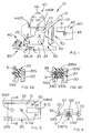
- FIG. 1 is a side view of a laser level according to the invention;
- FIG. 2 is a partial cross-sectional view along line A-A of FIG. 1, where FIGS. 2A-2B show two different embodiments;
- FIG. 3 is a bottom plan view of the laser level;
- FIG. 4 is a cross-sectional view along line B-B of FIG. 3;
- FIG. 5 is a top plan view of the show assembly;
- FIG. 6 is a partial top plan view along line C-C of FIG. 1;
- FIG. 7 illustrates a clamp assembly, where FIGS. 7A-B show the clamp assembly in the open and closed positions, respectively, and FIG. 7C is a partial top plan view along line A-A of FIG. 7A;
- FIG. 8 illustrates the engine assembly, where FIGS. 8A-D are right side, rear, front and left side views, respectively;
- FIG. 9 is a first engine assembly locking mechanism;
- FIG. 10 is a second engine assembly locking mechanism;
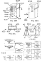
- FIG. 11 is a rear view of a multi-battery adapter assembly;
- FIG. 12 is a partial cross-sectional view of the multi-battery adapter assembly along line A-A of FIG. 11;
- FIG. 13 illustrates a battery ejector assembly, where FIGS. 13A-C are partial cross-sectional views of the assembly;
- FIG. 14 is a top plan view of the engine assembly;
- FIG. 15 is a partial front view of a laser assembly along line A-A of FIG. 8A;
- FIG. 16 is a perspective view of a link of the laser assembly of FIG. 15;
- FIG. 17 is a cross-sectional view along line A-A of FIG. 15;
- FIG. 18 is a cross-sectional view along line B-B of FIG. 15;
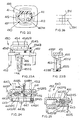
- FIG. 19 is a cross-sectional view along line X-X of FIG. 20;
- FIG. 20 is a cross-sectional view along line D-D of FIG. 8B
- FIG. 21 is an alternate cross-sectional view along line D-D of FIG. 8B;
- FIG. 22 is a partial top plan view along line E-E of FIG. 8C;
- FIG. 23 illustrates a vial plate of the laser assembly, where FIG. 23A is a front view and FIG. 23B is a side view along line A-A of FIG. 23A;
- FIG. 24 is a cross-sectional view along line C-C of FIG. 8A;
- FIG. 25 is a cross-sectional view along line B-B of FIG. 8C;
- FIG. 26 is a diagrammatic view of the laser beam;
- FIG. 27 illustrates the bump sensor assembly, where FIG. 27A is a bump sensor assembly, FIG. 27B is a circuit schematic of the bump sensor assembly, and FIG. 27C is a bump sensor assembly including a mechanical amplifier assembly;
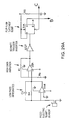
- FIG. 28 is a block diagram illustrating a bump sensor circuit;
- FIG. 29 is a circuit schematic of the bump sensor circuit of FIG. 28, of which FIGS. 29A-C illustrate different portions of the bump sensor circuit, where leads B and C in FIG. 29A connect to leads B and C in FIG. 29C, and lead A in FIG. 29B connects to lead A in FIG. 29C;
- FIG. 30 illustrates a laser level used in conjunction with a light detector;
- FIG. 31 is a block diagram illustrating the light detector circuit;
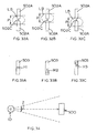
- FIGS. 32A-C are diagrammatical plane views illustrating the relation between the measuring light beam and the light-receiving section;
- FIGS. 33A-C are plane views illustrating display patterns in the display sections;
- FIG. 34 is a top plan view of the laser level used in conjunction with the light detector;
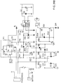
- FIG. 35 illustrates the motor speed control circuit, where FIG. 35A is a block diagram of the circuit, and FIG. 35B is the circuit schematic for such circuit; and
- FIG. 36 illustrates a light detector according to the invention, where FIG. 36A is a front perspective view thereof, FIG. 36B is a rear perspective view thereof, and FIG. 36C is a partial cross-sectional view along line A-A of FIG. 36A.
-
- The invention is now described with reference to the accompanying figures, wherein like numerals designate like parts. Referring to FIG. 1, a
laser level 10 preferably comprises aframe assembly 30, anengine assembly 40 rotatably attached to frame assembly30, a laser diode assembly 410 (shown in FIG. 20) disposed withinengine assembly 40, aprotective assembly 20 connected to frameassembly 30, ashoe assembly 50 slidably attached toprotective assembly 20, aclamp assembly 80 disposed onshoe assembly 50, and amulti-battery adapter assembly 70 for receiving abattery 60. These assemblies are discussed in further detail below. - Preferably,
protective assembly 20 has at least oneprotective bar 22 flexibly connected to theframe assembly 30.Such bar 22 may be made of aluminum, or other suitable material. Preferably, thebar 22 is made of a plastic, such as ABS or polypropylene. Thebar 22 may be injection-molded. Alternatively, the plastic may be injected into a mold (preferably about half the volume needed to complete fill the mold and thus filling half of the mold), then air or gas is blown therein, pushing the plastic into the other half of the mold, forming a hollow tube. This process is known as gas-assist injection molding. - The entire
protective assembly 20 may be constructed as discussed above. Preferably, theprotective assembly 20 surrounds and/or is disposed on both sides offrame assembly 30. A handle 21 may be disposed between bars 22. Handle 21 may be fixedly attached to thebars 22 via, e.g., screws (not shown). - Preferably, the shape of
protective assembly 20 and handle 21 is such that theframe assembly 30 and/orengine assembly 40 cannot be contacted by anything wider than the handle 21 and/orprotective assembly 20. Such construction minimizes the risk of damage to frameassembly 30 and/orengine assembly 40. - As mentioned above, the
protective assembly 20 may be flexibly connected to theframe assembly 30. Such connection is achieved via theconnector assemblies 23. Referring to FIG. 2A, aconnector assembly 23 is disposed between theprotective assembly 20 and awall 31 offrame housing 30. Theconnector assembly 23 comprises aflexible isolator 23G, which is preferably made of a flexible, resilient material such as rubber or an elastometer. Theisolator 23G may be connected to theprotective assembly 20 andwall 31 via a screw 23S, which may extend through one of theprotective assembly 20 and/orwall 31 and threadingly engage the other of theprotective assembly 20 and/orwall 31. - Alternatively, a
isolator 23G' may be connected toprotective assembly 20 via a screw 23S' extending through theprotective assembly 20 and entering intoisolator 23G', or vice versa, as shown in FIG. 2B. Screw 23S' may then threadedly engage a nut 23SN. Theisolator 23G' in turn may be connected to thewall 31 via ascrew 31S extending through thewall 31 and entering intoisolator 23G', or vice versa.Screw 31S may then threadedly engage a nut 31SN. Isolator 23G' may be molded over screws 23S', 31S and/or nuts 23SN, 31SN. Such construction minimizes the shock received byframe assembly 30 and/orengine assembly 40, and thus by the circuitry and components mounted within, whenlaser level 10 is dropped. - Referring to FIGS. 1 and 3-6,
shoe assembly 50 may be slidably connected toprotective assembly 20.Protective assembly 20 may have tworails 24 surroundingshoe assembly 50.Shoe assembly 50 may have aplate 51, with tabs 51T extending therefrom.Plate 51 is preferably made of plastic. Preferably, eachrail 24 has agroove 24G for receiving tab 51T. Accordingly,shoe assembly 50 can slide relative toprotective assembly 20 via the groove/tab connection. Persons skilled in the art should recognize that the same result would be achieved ifprotective assembly 20 andshoe assembly 50 had tabs and channels disposed respectively thereon. -
Shoe assembly 50 may have at least one rack 51R (and preferably two racks 51R) disposed onplate 51. Such rack 51R engagespinion 24P disposed on a shaft 24S, which may extend betweenrails 24. - Shaft 24S preferably carries rotatable knob 24RK at one end of the shaft. Rotatable knob 24RK is fixedly connected to shaft 24S. Accordingly, a user can rotate the
pinions 24P by rotating rotatable knob 24RK. As thepinions 24P rotate, theplate 51 will move forwardly or rearwardly. Travel ofplate 51 may be limited by disposingenlarged teeth 51 RT at the beginning and/or the end of rack 51R. Becausepinion 24P will not be able to mesh with enlarged teeth 51RT,pinion 24P will not rotate any further and travel ofplate 51 in that direction is limited. - Shaft 24S may also carry locking knob 24LK at its other end of the shaft. Locking knob 24LK may threadingly engage shaft 24S. Accordingly, when a user rotates locking knob 24LK, the knob will pinch
rails 24 between locking knob 24LK and rotatable knob 24RK, lockingplate 51 in place. Therefore, the user can fix and lock theshoe assembly 50 relative toprotective assembly 20 by rotating locking knob 24LK. -
Plate 51 may also have strengthening ribs 51SR for strengthening theplate 51.Plate 51 may also have anopening 510 for reducing the weight of and/or the amount of materials used inplate 51. Opening 510 may also allow viewing of the cast laser beam on a floor or work surface.Plate 51 may also have a threaded tripod mount 51TM. -
Plate 51 may also have wall mount holes 51WM for receiving at least one nail or screw mounted on a wall, allowing the user to hang thelaser level 10 from a wall. The verticality oflaser level 10 can then be adjusted by rotating knob 51K. Knob 51K preferably extends through and threadingly engagesplate 51. A pad 51KP may be disposed at the end of knob 51K.Pad 51 KP may be made of plastic or rubber.Pad 51 KP may be fixed or captured on knob 51K via a screw 51KPS and/or washer (not shown), or may snap into a feature of rotating knob 51K. Accordingly, the distance betweenplate 51 and the wall may be adjusted by rotatingknob 51 K. Because pad 51KP may be free to swivel about knob 51K, it can be used on uneven or unlevel surfaces. - Referring to FIGS. 1, 5 and 7,
plate 51 may also supportclamp assembly 80.Clamp assembly 80 may be used for clampinglaser level 10 onto a ceiling, etc. Preferably,plate 51 has a vertical wall 51W, which is pivotally connected to clampingwall 81. Clampingwall 81 may have protrusions 81 P for enhancing the clamping of a surface. Similarly, wall 51W may have protrusions (not shown) for enhancing the clamping of a surface. Persons skilled in the art will recognize that a surface will be clamped between wall 51W and clampingwall 81. - Preferably, clamp
assembly 80 can be opened and closed. This can be accomplished in different manners. One such manner provides clampingwall 81 with anextension arm 81A, which may be substantially perpendicular towall 81. Ashaft 85 may extend througharm 81A and is pivotally connected to acam 83 via apin 85P. Persons skilled in the art will recognize thatarm 81A may be contacted underneath by thehead 85H ofshaft 85 and/orspring 84, which may be captured betweenarm 81A andshoulder 85S ofshaft 85. Because of this,arm 81A (and thus wall 81) will move whenshaft 85 moves upwardly. -
Cam 83 may fixedly attached toshaft 82, which may be rotated bylever 86. Accordingly, whenshaft 82 is rotated in one direction,cam 83 is rotated is rotated in the same direction, movingshaft 85 upwardly, which in turn movesarm 81A upwardly, rotating clampingwall 81 towards wall 51W. In other words, clampassembly 80 is thus closed. Ifshaft 85 bottoms out,spring 84 can movearm 81A further. - Preferably, a
torsion spring 81S may be disposed between clamping wall 81 (orarm 81A) and wall 51W. Whencam 83 is rotated in the other direction, the force pressed ontoarm 81A byshaft 85 and/orspring 84 is diminished.Torsion spring 81S then forces the wall 81 (orarm 81A) away from wall 51W. In other words, clampassembly 80 is thus opened. Therefore, clampassembly 80 may be opened or closed by rotation ofshaft 82. - It is preferable to provide
shaft 82 with apin 82P travelling along a channel 51C inplate 51 to limit the range of rotation ofshaft 82. This prevents a user from overtighteningclamp assembly 80. - Preferably, wall 51W has zero markings 51ZI.
Plate 51 may also haveindicia 511 to indicate the distance between the clampingwall 81 and/or wall 51W (or zero marking 51Zl) and theframe assembly 30. Accordingly, the user can precisely determine whether theframe assembly 30 and/orengine assembly 40 is at, e.g., two inches from the clampingwall 81 and/or wall 51W. - As mentioned above,
engine assembly 40 is pivotally attached to frameassembly 30, as shown in FIGS. 1 and 8. In other words,engine assembly 40 may be rotated from a substantially vertical position for radiating a laser beam LB along a horizontal plane to a substantially horizontal position (shown in dotted lines) for radiating laser beam LB along a vertical plane. Persons skilled in the art will recognize that, if the vertical position is 0° and the horizontal position is 90°, it is preferable to allow rotation ofengine assembly 40 from about -5° to 140°. - Referring to FIGS. 1 and 8-10, a
shaft 32 extends throughframe assembly 30 andengine assembly 40, allowingengine assembly 40 to rotate thereabout.Engine assembly 40 may have arack 49R which meshes with apinion 35 supported byframe assembly 30. Accordingly, the user can precisely rotateengine assembly 40 by rotatingpinion 35. It is preferable to provide a pointer 31 P andindicia 421 onwall 31 andengine assembly 40 to indicate the angle ofengine assembly 40 relative to frameassembly 30. - FIG. 9 illustrates a first locking mechanism for fixing the angular position of
engine assembly 40. As mentioned above,shaft 32 extends through right wall 31 R,engine assembly 40 and leftwall 31 L. Acam 33 may be pivotally attached toshaft 32 via pin 33P. When a user rotatescam 33 viahandle 33H,camming portion 33C increases the distance between pin 33P and leftwall 31 L. Such actionlocks engine assembly 40 by pinchingengine assembly 40 betweenwalls 31 R, 31 L. Alternatively, ifengine assembly 40 is fixedly connected, no pinching is necessary, as thecamming portion 33C will prevent rotation ofshaft 32 until released. - FIG. 10 illustrates a second locking mechanism for fixing the angular position of
engine assembly 40, where like numerals refer to like parts. As mentioned above,shaft 32 extends through right wall 31R (not shown),engine assembly 40 and leftwall 31L.Engine assembly 40 is preferably fixedly attached toshaft 32. Adetent mechanism 34 may be pivotally attached toshaft 32 viapin 34P.Detent mechanism 34 preferably has adetent protrusion 34D, which may engage a notch 31 N inleft wall 31L. - Accordingly, the angular position of
engine assembly 40 may be fixed by the location of the notch 31 N engaged byprotrusion 34D. To unfix the angular position, the user needs to movehandle 34H untilprotrusion 34D clears notch 31 N. The user can then change the angular position ofengine assembly 40. - Persons skilled in the art should recognize that multiple angular positions of
engine assembly 40 may be available by providing multiple notches 31N at different angles. Persons skilled in the art shall recognize that detent protrusion and notches could have been disposed alternatively on thewall 31 L anddetent mechanism 34 to achieve the same result. - Persons skilled in the art should also recognize that it is preferable to provide a spring 34S between detent mechanism 34 (preferably handle 34H) and
wall 31L to bias theprotrusion 34D into engagement with notch 31N. Preferably, spring 34S is an extension spring. Alternatively, spring 34S could be a compression spring if disposed in the appropriate manner. - A preferred embodiment of the
engine assembly 40 is shown in FIGS. 15-25. Persons skilled in the art should refer to US Patent No. 5,754,582, which is wholly incorporated by reference herein.Engine assembly 40 may include alaser assembly 400.Laser assembly 400 may include alaser diode assembly 410, a drivingassembly 420 for rotating thelaser diode assembly 410, and a poweringassembly 430 for powering the laser diodes in thelaser diode assembly 410. -
Laser diode assembly 410 preferably includes alaser diode housing 411, which is preferably made of aluminum.Laser diode housing 411 may have twocylindrical bores 412, which are preferably coplanar. (Persons skilled in the art should recognize that the number ofbores 412 provided may match the number of laser diodes modules disposed in the housing. In the preferred embodiment, two laser diode modules are to be disposed inlaser diode housing 411, for reasons further explained below.) -
Laser diode assembly 410 may also include abarrel 413 inserted into eachbore 412.Barrels 413 carry thelaser diode modules 415. Preferably, the present invention employs a low cost laser diode module such as that used in laser pointers. These laser diode modules include a laser diode source and anoptical system 415L disposed onbarrel 413, which is preferably made of aluminum. The optical components are inexpensive and the alignment process is quick and simple. A standard low cost laser diode module consists of alaser diode 415D and a printedcircuit board 415P for mounting thediode 415D. Preferably,diode 415D is Sanyo part numbers DL-3148-033 or DL-3148-034. - Printed
circuit board 415P may carry a power regulation integrated circuit for limiting the power sent tolaser diode 415D and/or limiting the brightness oflaser diode 415D. One suitablelaser diode module 415 may be the VLM-670 available from Quarton Company of Taipei, Taiwan. In a typical manufacturing process for these laser diode modules, thelaser diode 415D is glued or soldered to the printedcircuit board 415P. - In addition,
barrel 413 may be pivotally attached tolaser diode housing 411 via apin 414, which is preferably disposed substantially horizontally. Accordingly,barrel 413 may be adjusted rotationally aboutpin 414, allowing the pitch ofbarrel 413 to be adjusted. This may be accomplished by disposingbarrel 413 between aspring 417 and aset screw 416. - To adjust the barrel 413 (and thus laser diode module 415), the assembler needs only to rotate set
screw 416. Ifscrew 416 is rotated for downward movement,barrel 413 will move downwardly. On the other hand, ifscrew 416 is rotated for upward movement,barrel 413 will move upwardly due tospring 417. Preferably, setscrew 416 is locked in place with a quick drying adhesive, such as Loc-Tite, etc. Persons skilled in the art will recognize that this adjustment methodology is preferable so that the position of thelaser diode module 415 is not susceptible to disturbance due to vibration during the transportation of thelaser level 10. - Persons skilled in the art will recognize that
laser diode housing 411 may have abore 417B for receivingspring 417 therein, as well as ahole 417H for facilitating insertion ofspring 417 therein. -
Laser diode housing 411 is preferably disposed on ashaft 419, which may be electrically charged, as explained below. Preferably,shaft 419 is made of metal, such as aluminum or steel, and carries a positive charge. Awire 419P may connect theshaft 419 to the laser printedcircuit board 415P. Alternatively, laser printedcircuit board 415P may be connected tobarrel 413, which in turn is electrically connected to laser diode housing 411 (and shaft 419) viapin 414,screw 416 and/orspring 417. -
Shaft 419 may be hollow to carry anegative wire 415N.Negative wire 415N preferably extends throughshaft 419 andbarrel 413, and is connected to the laser printedcircuit board 415P. -
Shaft 419 may be rotatably supported by avial assembly 450, which includesvial plate 451. Preferably, a bearing 419B is disposed onvial plate 451. Bearing 419B may rotatably receiveshaft 419 therethrough. Persons skilled in the art will recognize that bearing 419B minimizes friction betweenshaft 419 andvial plate 451. In addition, bearing 419B may be pre-loaded axially to reduce clearances within the bearing itself. Lack of bearing pre-load may result in calibration drift, affecting the accuracy oflaser assembly 400. - In addition, an insulating
layer 4191 may be disposed between bearing 419B andvial plate 451. In this manner, the electrical charge ofshaft 419 will not be conducted tovial plate 451 and/orvial assembly 450. Alternatively, electro-static discharge (ESD) from exposed metal surfaces will not be conducted to thediodes 415D, which may be sensitive to ESD. - It is preferable to provide a
cap 418 onlaser housing 411 to prevent users from touching and/orviewing wires cap 418 is made of an insulating material, such as rubber or plastic, and is designed so that it snaps ontohousing 411. - Persons skilled in the art will recognize that the laser beam LB may have a cross-section that is longer along a first axis than along a substantially perpendicular axis. In other words, its height may be larger than its width (see, e.g., beam spot LBV in FIG. 26), etc. This is because the laser emission is generated by light oscillating at resonance within an active semiconductor layer, that is sandwiched between two internally highly reflective semiconductor faces. Collimating optics in the
laser diode module 415 may reshape this light into a more equal-dimensioned beam. However, even after collimation, the laser beam LB is not perfectly circular. - It is preferable thus to align the
laser diode module 415 so that the longer axis of the beam spot is disposed substantially horizontally, i.e., along and/or coplanar to the laser light plane generated by the laser level 10 (see, e.g., beam spot LBH in FIG. 26). This minimizes the height of the laser beam, providing for a more exact, or "crisper," laser light plane. - Such result can be achieved, for example, as follows. First, the orientation of the semiconductor material layers within the laser crystal must be identified. The orientation is typically fixed with respect to three electrical pins on the
laser diode 415D. Once the orientation of the layers and pins has been identified, the printedcircuit board 415P may be designed to receive thelaser diode 415D in a certain rotational position. Printedcircuit board 415P may also be provided with anindexing tab 4151. Thistab 4151 fits in a slot (not shown) inbarrel 413, fixing the rotational position of thelaser diode module 415 relative to thelaser diode housing 411. Accordingly, thelaser diode module 415 can be consistently installed so that the longer axis of the beam spot is disposed substantially horizontally, i.e., along and/or coplanar to the laser light plane generated by thelaser level 10. Persons skilled in the art shall recognize that the tab and slot may be alternative provided onbarrel 413 and printedcircuit board 415P, respectively. - Persons skilled in the art should recognize that
wall 41 ofengine assembly 40 substantially encloses and/or protectslaser assembly 400.Slots 41S may be disposed onwall 41 to allow laser beam LB to exit therefrom. - Preferably,
laser assembly 400 has twodiode modules 415. One reason for such arrangement is the added intensity of the resulting laser beam plane. - Another reason is that having two
diode modules 415 will prevent any unlighted spots on the laser beam plane. As shown in FIG. 14, theslots 41S are preferably separated byposts 41 P. Preferably the width ofposts 41P is such that, when onelaser diode module 415 is blocked by onepost 41P, the otherlaser diode module 415 projects a laser beam LB that exists throughslot 41S. - As mentioned above, powering
assembly 430 provides power tolaser diode modules 415. Poweringassembly 430 may include aslip ring 431, which is preferably integrated. Preferably,slip ring 431 is fixedly disposed to afloor 441. Abracket 432 may be used to fixslip ring 431 untofloor 441. -
Slip ring 431 may receive power through positive wire 431WP and negative wire 431WN. Theslip ring 431 may be electrically connected to ashaft 433, via brushes 431 B,rendering shaft 433 with a particular electrical potential.Shaft 433 is preferably made of metal, such as steel or aluminum. Preferably,shaft 433 has a positive voltage. -
Slip ring collar 434 may be disposed at and electrically connected to the upper end ofshaft 433. Persons skilled in the art will recognize thatslip ring collar 434 is also electrically charged. A dual constant velocity joint (or universal joint) may connect theslip ring collar 434 to apulley 422, as explained below. Alight spring 435 may bridge the electrical gap between theslip ring collar 434 andpulley 422.Spring 435 may also slightly preload the joint to eliminate backlash. - As mentioned above, driving
assembly 420 is provided forrotating laser assembly 410. Drivingassembly 420 may include amotor 424 driving a shaft 424S and apulley 424P disposed thereon.Pulley 424P may drive abelt 423, which drivespulley 422.Pulley 422 is preferably fixedly attached toshaft 419. Accordingly, whenmotor 424 rotates shaft 424S, it will drivepulley 422 and rotateshaft 419. -
Motor 424 may be supported byvial assembly 450,plate 451 and/or by a bracket connected thereto. Themotor 424 is preferably controlled and/or driven by a pulse width modulation (PWM) circuit, which is shown in FIG. 35A as a block diagram, and in FIG. 35B as a circuit schematic. - The user
adjustable voltage 601 includes apotentiometer 601 P, which can be moved by a user. Thepotentiometer 601 P varies the selected voltage between a top voltage representative of the top rotational speed ofmotor 424, and a bottom voltage, where themotor 424 does not rotate. Preferably, the bottom voltage is slightly negative. - The selected voltage is then fed to a
summer 602, which substracts the motor's back electromotive force (emf) feedback voltage from the selected voltage. The emf voltage is determined by the sample and hold 605 as follows. Persons skilled in the art will recognize thatmotor 424 is driven by pulses. The longer and/or the more frequent the pulses, the longer themotor 424 runs on electricity, allowing it to accelerate. - When the
motor 424 is not driven by a pulse, themotor 424 acts as an inductor and creates a flyback (negative) voltage. This flyback voltage is then shunted. - When the flyback voltage is shunted,
motor 424 is freewheeling and generating voltage. In particular,motor 424 generates back emf voltage, which is relatively proportional to the rotational speed ofmotor 424. The sample and hold 605 then samples the back emf voltage, holds it and then sends it summingjunction 602. - Summing
junction 602 generates an error signal which goes intocontroller 603.Controller 603 then sends a drive signal to thePWM motor drive 604, which sends out the drive pulses to drivemotor 424. ThePWM motor drive 604 also sends a signal indicating that it is drivingmotor 424 to the sample and hold 605. In this manner, sample and hold 605 does not sample the voltages created bymotor 424 at the same time thePWM motor drive 604 is driving themotor 424. - Sample and hold 605 also has another circuit that monitors the flyback voltage, to prevent sampling thereof. Once the flyback voltage is shunted, sample and hold 605 can sample the back emf voltage.
- Persons skilled in the art should recognize that
controller 603 may require both positive and negative supply voltages. Since thelaser level 10 is preferably battery powered, avoltage inverter 606 has been provided to invert the battery voltage, thus providing the negative supply voltage tocontroller 603. - Persons skilled in the art will recognize that FIG. 35B illustrates one possible implementation of the circuit diagrammed in FIG. 35A. Persons skilled in the art will also be able to build and analyze the operation of the circuit shown in FIG. 35B. The values of the different components shown in the schematics are as follow:
- C1
- 10µF
- C2
- 10µF
- C3
- 01µF
- C4
- 33µF
- C5
- 22µF
- C6
- 100µF
- C7
- 22µF
- C9
- 01µF
- C10
- 10µF
- D1
- 1N4148
- D2
- 1N5228
- D3
- 1N4148
- D4
- 1N4148
- D5
- 1N4148
- D6
- 1N4148
- D7
- 1N5818
- D17
- 1N4148
- Q1
- 2N3906
- Q2
- 2N3906
- Q3
- 2N3906
- Q4
- 2N3904
- R1
- 10KΩ
- R2
- 1KΩ
- R3
- 11KΩ
- R4
- 20KΩ
- R5
- 39KΩ
- R6
- 3KΩ
- R7
- 15KΩ
- R8
- 3Ω
- R9
- 1KΩ
- R10
- 1KΩ
- R11
- 1KΩ
- R12
- 10KΩ
- R13
- 10KΩ
- R14
- 10KΩ
- R15
- 38KΩ
- R16
- 10KΩ
- R17
- 10KΩ
- R18
- 10KΩ
- R19
- 10KΩ
- R21
- 1KΩ
- R22
- 10KΩ
- R38
- 1KΩ
- R39
- 10KΩ
- R43
- 1.1KΩ
- U1
- 74HC4316
- U2
- 74HC14
- U3
- 74HC4066
- U4
- LM311
- U5
- LM324
- U6
- LM311
- Persons skilled in the art will recognize that in the circuit shown in FIG. 35B, integrated circuits U2A, U2B and U1 are configured as a switched capacitor voltage converter to generate a negative voltage for the operational amplifier U2 and the low end of the command signal (to ensure head rotation stops when the speed adjustment potentiometer, R18, is turned off). Q1, U4 and U6 are configured as a PWM drive. The duty cycle is controlled by the controller output (the voltage at U6, pin 2). Q3 is the motor drive transistor and Q2 combined with R8 limit the drive current to approximately 230 mA. U3D and C9 are a sample and hold circuit. Sampling is allowed when the drive pulse is off (U2, pin 8) and when the motor coil flyback pulse is over (controlled by D4, D5, D6 and Q4). R21 and C8 forms low pass filter to reduce sampling noise. USD buffers the feedback voltage. U5C buffers the command voltage. U5A subtracts the feedback from the command to create an error signal. U5B is a proportional and integral controller that commands the PWM circuitry to drive the error signal to zero. This holds the rotary head speed constant at a speed controlled by the user adjusting R18.
- Persons skilled in the art should recognize that most of the circuit shown in FIG. 35 should be disposed within
frame assembly 30. - In addition, driving
assembly 420 may include acoupling link 421, which is preferably disposed onslip ring collar 434.Link 421 may be made of a nonconductive material, such as plastic. As shown in FIGS. 16-18, link 421 has at least oneupper protrusion 421 P and at least onelower protrusion 421 LP extending from a shaft 421S. Preferably, link 421 has fourupper protrusions 421P extending in a cross formation from shaft 421S. Similarly, link 421 may have four lower protrusions 421LP extending in a cross formation from shaft 421S. Preferably, link 421 is injection molded to obtain the desired shape. - Lower protrusions 421LP may be disposed in a similarly shaped area of
slip ring collar 434. Preferably, agap 434G exists between lower protrusion 421LP andslip ring collar 434 to allow some rotational play therebetween. - Similarly,
upper protrusions 421P may be disposed in a similarly shaped area ofpulley 422. Preferably, agap 422G exists between lower protrusion 421LP andpulley 422 to allow some rotational play therebetween. - Because of the shape of the
protrusions 421P, 421LP, the shape of the slots inpulley 422 and slipcollar 434, and thegaps shaft 419 andpulley 422 is transmitted throughlink 421 toshaft 433. Accordingly, this system behaves like a double-knuckle joint, compensating for misalignment between theslip ring 431, theshaft 433 andpulley 422 via six degrees of freedom (three translational degrees and three rotational degrees). This also minimizes stress on theslip ring 431. - Referring to FIG. 15, as mentioned above,
slip collar 434 is electrically charged. This charge may be transmitted topulley 422 via aspring 435.Shaft 419 is then charged due to the electrical connection betweenpulley 422 andshaft 419. Persons skilled in the art will recognize thatspring 435 may also serve to maintain alignment betweenslip collar 434 andpulley 422. - On the other hand, a
wire 431N exitingslip ring 431 may carry the opposite charge tolaser diode module 415. Ifshaft 419 is charged positively, then wire 431N carries the negative charge.Wire 431 N preferably bypassesshaft 433 and slipcollar 434, and entersshaft 419 throughpulley 422. As mentioned above,shaft 419 is hollow, allowing wire to extend therethrough until it is electrically connected to wire 415N. - Referring to FIGS. 20-21,
manual adjustment assemblies 460, 460' may be provided onengine assembly 40, for manuallyrotating laser assembly 410. Referring to FIG. 20, aplate 462 may be fixedly attached to wall 41 ofengine assembly 40. Preferably,plate 462 is riveted untowall 41. Anadjustment knob 461 may be disposed betweenwall 41 andplate 462, and extend through the top ofengine assembly 40. Aspring 463 is preferably disposed betweenknob 461 andplate 462. Aplunger 465 may be disposed underknob 461.Plunger 465 may extend throughplate 462 for contactinglaser diode housing 411. Preferably, the plunger areas that contactlaser diode housing 411 are rubberized, or covered with a high friction material. Alternatively,plunger 465 is made of rubber.Tabs 465T may captureplunger 465 betweenplate 462 andknob 461. Aspring 464 may be disposed betweenplunger 465 andknob 461. - Accordingly, if the user wants to adjust the location of
laser diode housing 411, the user needs only to pressknob 461 downwardly, forcingplunger 465 into contact withlaser diode housing 411. The user can then rotatelaser diode housing 411 by rotatingknob 461. The user cannot overload thelaser diode housing 411 because the spring preferably 464 maintains a controlled contact force betweenplunger 465 andlaser diode housing 411. In addition,adjustment knob 461 and/orspring 463 preferably bottom out onplate 462 beforespring 464 is fully compressed. - As shown in FIG. 21, adjustment assembly 460' is similar to
adjustment assembly 460, where like numerals refer to like parts. The main difference between the two embodiments is thatplunger 465 is retained by retainingpin 466, rather thantabs 465T contactingplate 462. Preferably,pin 466 is fixedly attached toknob 461. - Referring to FIGS. 8, 14-15 and 23,
vial assembly 450 preferably has avial plate 451 andpedestals 452 for supportingvial plate 451 onfloor 441. Preferably, aninsulation pad 4521 is disposed betweenpedestals 452 andfloor 441 for electrically insulatingvial assembly 450 fromfloor 441. -
Vial plate 451 may carry multiple spirit vials thereon to indicate whethervial plate 451 and/orlaser diode modules 415 are in a substantially horizontal plane. Preferably,vial plate 451 carries at least three horizontal vials 454VF, 454VS, 454VR and onevertical vial 455V. The horizontal vials 454VF, 454VS, 454VR are preferably disposed on the front, right and rear walls ofengine assembly 40.Vertical vial 455V may be disposed on the rear wall ofengine assembly 40. - Suitable vials for this application may be parts nos. 0349 and/or 0224 made by Empire Level Mfg. Corp. of Milwaukee, Wis. Alternatively, the vials can be custom made by bending or grinding, as is well known in the art, so long as the desired dimensional requirements are met.
- In the present case, the main dimensional requirements for the vials are length, diameter and angular sensitivity. Persons skilled in the art will recognize that length and diameter are dependent upon the size of the desired vial.
- As to angular sensitivity, persons skilled in the art will recognize that the angular sensitivity of the vials is identified by "minutes", as in "one-minute vials." The vials used in
laser level 10 may be more accurate, equally accurate or less accurate than one-minute vials. Preferably, the vials used in thelaser level 10 are one-minute vials, five-minute vials, six-minute vials, or any other vials with an angular sensitivity between the one-minute vials and the six-minute vials. - Such arrangement is advantageous for several reasons. First, when
engine assembly 40 is in the vertical position, the user may want to check vials 454VS and 454VF and/or 454VR to determine whether thelaser diode modules 415 are level. However, whenengine assembly 40 is in the horizontal position, the user may not be able to check vials 454VS and/or 454VF. The user can nevertheless confirm whetherlaser diode modules 415 are substantially vertical, or "plumb," by checking vials 454VR and 455V, which are now laying substantially horizontally on the rear face. - Another reason for providing parallel vials 454VF, 454VR is to provide redundant alignment indication. In other words, both vials may be calibrated to indicate level when the laser beam plane is horizontal. If the
laser level 10 is disturbed violently enough for one of the vials to become uncalibrated with respect to the laser beam plane, the user can notice such problem by comparing both vials 454VF, 454VR. - Referring to FIG. 23, vials 454VR, 455V may be attached to
vial holders vial holders -
Vial holder 454 may be pivotally attached tovial plate 451 viapin 454P. Alternatively,vial holder 454 may be flexibly attached tovial plate 451 via a flexible junction or flexure. The flexible junction may be integral withvial holder 454 and/orvial plate 451, or it may be bonded tovial holder 454 and/orvial plate 451. Persons skilled in the art should recognize that the flexure may be mounted to the vial plate, and a vial may be bonded on the flexure. - An
adjustment screw 454B may extend throughvial plate 451 and threadingly engagevial holder 454. Aspring 454S may be disposed betweenvial plate 451 andvial holder 454. Preferably,spring 454S is a compression spring.Spring 454S may be disposed along oroutside screw 454B. Accordingly, when thescrew 454B is rotated,vial holder 454 will pivot aboutpin 454P.Spring 454S will maintain thevial holder 454 in the desired position. - Persons skilled in the art will recognize that
screw 454B may threadingly engage and extend throughvial holder 454 and contact (rather than extend through)vial plate 451. Alternatively, screw 454B may extend throughvial holder 454 and threadingly engagevial plate 451. - Similarly,
vial holder 455 may be pivotally attached tovial plate 451 via apin 455P. Alternatively,vial holder 455 may be flexibly attached tovial plate 451 via a flexible junction or flexure. The flexible junction may be integral withvial holder 455 and/orvial plate 451, or it may be bonded tovial holder 455 and/orvial plate 451. Persons skilled in the art should recognize that the flexure may be mounted to the vial plate, and a vial may be bonded on the flexure. - A pedestal or
protrusion 453 may extend downwardly fromvial plate 451. Ascrew 455B may extend throughprotrusion 452 and threadingly engagevial holder 455. Aspring 455S may be disposed betweenvial plate 451 andvial holder 455. Preferably,spring 455S is a compression spring.Spring 455S may be disposed along oroutside screw 455B. Accordingly, when thescrew 455B is rotated,vial holder 455 will pivot aboutpin 455P.Spring 455S will maintain thevial holder 455 in the desired position. - Persons skilled in the art will recognize that
screw 455B may threadingly engage and extend throughvial holder 455 and contact (rather than extend through)vial plate 451. Alternatively, screw 455B may extend throughvial holder 455 and threadingly engagevial plate 451. - Once the vials are adjusted, the
screws - Persons skilled in the art should recognize that the other vials may be adjusted in a similar manner.
- Referring to FIGS. 24-25, persons skilled in the art should also recognize that a
leveling mechanism 440 is preferably provided for adjusting the plane upon whichlaser assembly 410 rests, in order to ensure that the laser beam plane is substantially horizontal or substantially vertical.Leveling mechanism 440 includesfloor 441 upon whichlaser assembly 410 and/orvial assembly 450 rest thereon.Floor 441 may be disposed over aplate 443.Plate 443 may haveholes 443S for receivingshaft 32 therethrough. - Preferably,
floor 441 andplate 443 are connected. A screw 448 may threadingly engagefloor 441 andcontact plate 443. Aspring 448S may be disposed between thehead 448H of screw 448 andfloor 441 for biasingfloor 441 downwardly towardsplate 443. Similarly, ascrew 446 may threadingly engageplate 443 andcontact floor 441. A spring 446S may be disposed between thehead 446H ofscrew 446 andplate 443 for biasingplate 443 upwardly towardsfloor 441. Accordingly, the distance betweenfloor 441 andplate 443 may be adjusted by rotating screws 448 and/or 446. Aspring 447 may also be disposed betweenfloor 441 andplate 443. - Preferably,
floor 441 carries a pitch shaft 442PS, which can be rotated viapitch knob 442P. Shaft 442PS may be threadingly engaged to moveable pitch cam 442PC, so that when shaft 442PS is rotated, moveable pitch cam 442PC travels along the longitudinal axis of pitch shaft 442PS. Moveable pitch cam 442PC preferably contacts fixed pitch cam 443PC ofplate 443. As shown in FIG. 24, at least one of pitch cams 442PC, 443PC may have ramps for forcing moveable pitch cam 442PC (and floor 441) to move upwardly or downwardly. Persons skilled in the art should recognize that pitch shaft 442PS and moveable pitch cam 442PC may be disposed onplate 443, while fixed pitch cam 443PC may be disposed onfloor 441. Such arrangement allows the user to change the pitch angle offloor 441, i.e., to move the front offloor 441 upwardly while moving the rear offloor 441, or vice versa. - Persons skilled in the art will recognize that fixed pitch cam 443PC may be replaced by a pitch pin 443PP supported by walls extending from
plate 443. Pitch pin 443PP would function in the same manner as fixed pitch cam 443PC, except that pitch pin 443PP would be less sensitive to any rotational or angular variance of moveable pitch cam 442PC. -
Floor 441 may also carry a roll shaft 442RS, which can be rotated viaroll knob 442R. Shaft 442RS may be threadingly engaged to moveable roll cam 442RC, so that when shaft 442RS is rotated, moveable roll cam 442RC travels along the longitudinal axis of pitch shaft 442RS. Moveable roll cam 442RC preferably contacts fixed roll cam 443RC ofplate 443. As shown in FIG. 25, at least one of roll cams 442RC, 443RC may have ramps for forcing moveable roll cam 442RC (and floor 441) to move upwardly or downwardly. Persons skilled in the art should recognize that roll shaft 442RS and moveable roll cam 442RC may be disposed onplate 443, while fixed roll cam 443RC may be disposed onfloor 441. Such arrangement allows the user to change the roll angle offloor 441, i.e., to move the left side offloor 441 upwardly while moving the right side offloor 441, or vice versa. - Persons skilled in the art will recognize that fixed roll cam 443RC may be replaced by a roll pin 443RP supported by walls extending from
plate 443. Roll pin 443RP would function in the same manner as fixed roll cam 443RC, except that roll pin 443RP would be less sensitive to any rotational or angular variance of moveable roll cam 442RC. - Referring to FIGS. 27-29,
laser level 10 preferably has a bump sensor assembly 650 for indicating that thelaser level 10 has been hit or bumped, and potentially knocked out of level alignment. Bump sensor assembly 650, and its circuit, are preferably disposed onframe assembly 30. - Bump sensor assembly 650 preferably has a
sensor 651.Sensor 651 is preferably a thin piezoelectric element firmly mounted insidewall 32 offrame assembly 30. Such element is typically used in piezoelectric buzzers, and may consist of a thin slice of piezoceramic material sandwiched between two electrical contact plates. When the piezoceramic element is stressed mechanically, it generates an electrical charge across the contact plates. Piezoelectric elements do not typically respond to steady-state stress. - Accordingly, when
laser level 10 is bumped, the piezoceramic element is stressed, which in turn generates an electrical charge across the contact plates. Anamplifier 652 with a preferably high input impedance may electrically buffer, low-pass filter and/or amplify the output ofsensor 651. A voltage at the amplifier output exceeding a predetermined threshold, such as approximately 70% of the circuit supply voltage, may trigger thetiming circuit 653 to activate the alarms.Timing circuit 653 may include a flip-flop. Accordingly, if the amplifier output voltage is above the threshold, the flip-flop may be tripped and latched. - The
timing circuit 653 then may cause a light emitting diode (LED) 656 to flash untilmanual reset button 654 is activated. Similarly,timing circuit 653 may disable motor 658 (which preferably is motor 424) and/or may cause laser 657 (which preferably is laser diode module 415) to flash. Such alarms would indicate to the user that thelaser level 10 may be out of alignment. Again, themotor 658 and/orlaser 657 may be reset whenmanual reset button 654 is activated. - Bump sensor assembly 650 may also include a manual enable/disable
button 655 for allowing the user to enable and/or disable the bump sensor as desired. - Persons skilled in the art will recognize that FIGS. 29B-D illustrate one possible implementation of the circuit diagrammed in FIG. 29A. Persons skilled in the art will also be able to build and analyze the operation of the circuit shown in FIG. 29D. The values of the different components shown in the schematics are as follow:
- C1
- 0.01µF
- C3
- 10µF
- C4
- 10µF
- C5
- 10µF
- C6
- 10µF
- C7
- 0.47µF
- C8
- 22µF
- C9
- 0.01µF
- C11
- 22µF.25V
- C12
- 220µF.16V
- C13
- 22µF.25V
- C14
- 1µF.25V
- C15
- 1µF.25V
- D4
- 1N4148
- D5
- 1N5818
- D6
- IN5230
- D7
- 1N5813
- D9
- 1N4148
- D10
- LM385-1.2
- D11
- 1N4148
- D12
- 1N4148
- D13
- 1N4148
- D14
- 1N4148
- L1
- 330µH.1A
- Q1
- 2N4401
- Q2
- 2N4401
- Q3
- 2N4401
- Q4
- 2N4401
- Q5
- 2N4401
- Q7
- 2N4401
- Q8
- 2N4401
- Q9
- 2N4401
- Q10
- 2N4401
- R1
- 200KΩ
- R2
- 100KΩ
- R3
- 100KΩ
- R4
- 1MΩ
- R5
- 200KΩ
- R6
- 1KΩ
- R7
- 330Ω
- R8
- 10KΩ
- R9
- 10KΩ
- R10
- 200KΩ
- R11
- 300Ω
- R12
- 1MΩ
- R13
- 330Ω
- R14
- 75KΩ
- R15
- 10KΩ
- R16
- 750KΩ
- R17
- 510Ω
- R18
- 51KΩ
- R20
- 10KΩ
- R21
- 10KΩ
- R22
- 510Ω
- R24
- 51KΩ
- R25
- 10KΩ
- R26
- 1MΩ
- R27
- 1MΩ
- R28
- 10KΩ
- R29
- 10KΩ
- R30
- 10KΩ
- R31
- 51Ω
- R34
- 10KΩ
- U1
- 74HC74
- U2
- 74HC123
- U3
- LM358
- U4
- 74HC00
- U5
- 74HC14
- U6
- LM555C
- U7
- LM2574M-50 (manufactured by National Semiconductor Inc.)
- It may be preferable to mount a
mechanical amplifier assembly 660 untosensor 651. This is becausepiezoelectric sensor 651 typically responds only to high frequency strain caused by bumps or taps. Themechanical amplifier assembly 660 would increase the sensor's sensitivity to low frequencies by converting low frequency, i.e., slow, motions into high frequency taps which can be sensed bysensor 651. - The
mechanical amplifier 660 preferably includes a base 661 disposed on the piezoelectric element orwall 32, a shaft 662 extending therefrom, a spring 664 connected at one end to the end of shaft 662, and amass 663 connected to the other end of spring 664. Preferably, spring 664 is trapped betweenhead 662H andtrap 662T of shaft 662. Also, spring 664 may be trapped bymass 663 via screws 663S. - Accordingly,
mass 663 is preferably suspended by spring 664. Preferably, shaft 662 extends throughmass 663 so thatmass 663 is centered along shaft 662. This makes the system sensitive to disturbances in all lateral directions, which would causemass 663 to tap shaft 662, creating a high frequency tap. In addition, the shaft 662 may limit the motion ofmass 663, which prevents over-stretching of spring 664.Mass 663 may also travel vertically along shaft 662 to make thesensor 651 sensitive to vertical motion. Preferably,mass 663 is disposed close tobase 661 so thatmass 663 can contact base 661 directly. - Referring to FIGS. 1 and 11-13,
laser level 10 may be powered by abattery 60.Battery 60 may be connected tolaser level 10 viaterminals 31T.Frame assembly 30 may have anopening 31F which allowsprotrusion 61 ofbattery 60 to enterframe assembly 30 andcontact terminals 31T. - Preferably,
battery 60 is one that is used with other power tools. Persons skilled in the art are referred to US Patent Nos. 5,391,972 and 5,144,217, which are wholly incorporated by reference herein. - Preferably, an
adapter assembly 70 is used to accept differently-shaped battery packs, especially those that may have the same terminal configuration, but different pack (62) or protrusion (61) shapes.Adapter assembly 70 may include aplate 71, which is preferably made of plastic.Plate 71 may have two opposite curved sides, which have substantially the same radius.Plate 71 may have a flange 71F on each of the curved sides. Flange 71F may be disposed along about 55°-60° of each curved side. Preferably, flange 71F is captured bycapture walls 31C inframe assembly 30. Preferably,plate 71 has apivot boss 71P, which may be captured between two clamshell halves offrame assembly 30, for allowingplate 71 to pivot thereabout. -
Plate 71 may have afirst opening 72 and asecond opening 73, which allow afirst battery 60 and a second battery (not shown), respectively, to extend therethrough. Accordingly, if a user wants to insert a first battery, the user would alignfirst opening 72 with opening 31 F. Alternatively, if the user wants to insert a second opening, the user would rotateplate 71 to alignsecond opening 73 with opening 31 F. -
Plate 71 may be provided with detent protrusions 71 D, which engage notches (not shown) disposed onframe assembly 30. Detent protrusions 71D may be disposed on tabs 71T, which preferably resiliently bias protrusions 71D towards engagement with the frame assembly notches. Accordingly, the two desired positions ofplate 71 can easily be located. - Persons skilled in the art shall recognize that the protrusions and notches may alternatively be disposed on
frame assembly 30 andplate 71, respectively. Persons skilled in the art should also recognize that a spring can be used, instead of tabs 71T, to bias protrusions 71 D towards the notches. -
Plate 71 may also havelatch notches latches 63 of thefirst battery 60 and the second battery (not shown), respectively. Preferably,latch notches latches 63 of the second battery (not shown) and thefirst battery 60, respectively. - A
battery ejector assembly 74 may be provided to prevent the wrong battery, i.e., the one that cannot engage the proper latch notch, from contactingterminals 31T.Battery ejector assembly 74 may include a button 74B, which is biased byspring 74S towards the battery pack. Preferably, button 74B extends through pivot boss 71B. A clip 71C may trap button 74B within pivot boss 71B. Accordingly, button 74B pushes the wrong battery pack away frompivot plate 71,frame assembly 30 andterminals 31T if the battery pack cannot engage the proper latch notch. - Another aspect of the invention is
laser detector 500. Light detectors have been heretofore applied in a variety of fields, which are constituted such that light rays are photoelectrically detected and a measurement result is displayed to measure the intensity of the light, a light-projected location, etc. For example, light detectors have widely been used in a surveying field, which are constructed such that a laser beam is ejected from a surveying instrument body and received at an object to be measured, and the center of the laser beam-projected location is located. In the light detectors of this kind, the light-receiving section for receiving the light and the display section for displaying the measurement results on the basis of a signal from the light-receiving section are ordinarily arranged together in the same plane. - However, since the display section for displaying the measurement result and the light-receiving section are arranged in the same plane in the conventional light detectors thus constituted, a surveying person is required to stand exactly opposed to the display section to accurately read the measurement result. As a result, there occurred an extremely inconvenient problem that the measuring light entering the light-receiving section is interrupted by the surveying person himself.
- Persons skilled in the art are hereby referred to US Patent Nos. 4,934,812 and 5,486,690, which are wholly incorporated herein by reference.
- According to the present invention, the
light detector 500 according to the present invention is used, for instance, in combination with alaser level 10. As shown in FIG. 30, thelaser level 10 is placed on a tripod 11. As thelaser diode assembly 410 rotates around a perpendicular axis thereof, laser beam LB is emitted from thelaser diode assembly 410 as a measuring light beam scanned in a horizontal plane. - The
light detector 500 which is to receive the laser beam LB emitted from thelaser level 10 is adapted to be attached to an appropriate upright face, such as a wall face, or agrade rod 504, held by a user. Thelight detector 500 may be moved along therod 504 to detect the height and the location of the center of the laser beam flux with reference to a standard plane F. - Thereby, the height and the location of a point or beam to be measured are measured by measuring the height and/or the location of the
light detector 500, or a standard horizontal plane in which the laser beam LB is to be scanned is determined by appropriately marking the center of the light flux of the laser beam LB on thegrade rod 504. - FIGS. 36A-C show the
light detector 500 in detail.Light detector 500 may have a front face 501F and a rear face 501R. A light-receivingsection 502 may be provided on front face 501F for photoelectrically converting the light beam LB entering therein. Preferably, light-receivingsection 502 recognizes changes in intensity, rather than the actual intensity, of the laser beam LB as it sweeps across light-receivingsection 502. A light-receiving face of the light-receivingsection 502 may be contained in substantially the same plane as the front face 501 F. - In addition,
display segments display segments - The light-receiving
section 502 may be constituted by a pair of upper and lower light-receivingsegments 502A. A boundary portion between the light-receivingsegments 502A, that is, the central position of the light-receivingsection 502, is a zone through which a standard horizontal plane of the laser beam LB is to pass. - Light detector may have an
operation switch 504 to be actuated when in use. - FIG. 31 shows a circuit construction of the
light detector 500. A pair ofphotoelectric elements 506 constituting the light-receivingsegments 502A may be connected to aprocessor 507.Processor 507 is adapted to compare the magnitudes of received light amounts of thephotoelectric elements 506 and to output a discrimination result thereof. Theprocessor 507 may be connected to adisplay control unit 508, which is adapted to select a display pattern in compliance with the output from theprocessor 507. Persons skilled in the art will recognize thatdisplay control unit 508 may be integrated intoprocessor 507. - The
display control unit 508 may be connected to adisplay section 509 adapted to display the display pattern responsive to the output from thedisplay control unit 508. - The following constitutes an exemplary use of the
light detector 500. While carefully observing an indication of thedisplay section 509, a surveying person moves thelight detector 500 alonggrade rod 504 along a substantially vertical direction, which is substantially perpendicular to the substantially horizontal plane of the laser beam LB. At the same time, the center position of the laser beam LB is determined by the following procedure. - As shown in FIG. 32A, when the light flux of the laser beam LB equally enters both the light-receiving
segments 502A, that is, when the center of the light flux-passing zone P of the laser beam LB passes through an intermediate point between both the light-receivingsegments 502A, i.e., thecenter point 502C of the light-receivingsection 502, a first display pattern H1 may be indicated in the display section 503 (as shown in FIG. 33A) to show that the center of the light flux of the laser beam LB coincides with thecenter point 502C of the light-receivingsection 502 of thelight detector 500. Preferably,detector 500 will have notches ortabs 503T disposed thereon to indicate to the user wherecenter point 502C is relative to thelight detector 500. - As shown in FIG. 32B, when the light flux-passing zone P of the laser beam LB is deviated into the upper light-receiving
segment 502A, a second display pattern H2 may be indicated in the display section 503 (as shown in FIG. 33B) to show that the center of the light flux of the laser beam LB deviates above thecenter point 502C of thelight receiving section 502. Therefore, in this case, thelight detector 500 should be moved upwardly. - Further, as shown in FIG. 32C, when the light flux-passing zone P of the laser beam LB deviates into the lower light-receiving
segment 502A, a third display pattern H3 may be indicated in the display section 503 (as shown in FIG. 33C) to show that the center of the light flux of the laser beam LB deviates under thecenter point 502C of the light-receivingsection 502 of thelight detector 500. Therefore, in this case, thelight detector 500 should be moved downwardly. - Persons skilled in the art will recognize that, in each of the above cases, the surveying person M can read the beam incidence results (the display patterns H1, H2, and H3) indicated in the
display section 503 on either front face 501F or rear face 501R. Therefore, the measurement could be accurately performed from any direction without fear of the interruption of the measuring light beam as occurred in the conventional detectors. Thus, the present invention largely contributes to the prevention of measuring errors and enhancement of the measuring efficiency. - Referring to FIG. 31,
laser detector 500 may have asound control unit 510 that responds to the output ofprocessor 507.Sound control unit 510 may control aspeaker 511 and/or a piezoelectric element 512. Persons skilled in the art will recognize thatsound control unit 510 may be integrated intoprocessor 507. - Such arrangement provides an aural feedback to the surveying person. For example,
processor 507 and/orsound control unit 510 may be programmed so thatspeaker 511 and/or piezo 512 will sound only when the center of the light flux-passing zone P of the laser beam LB passes through thecenter point 502C of the light-receivingsection 502. In addition,processor 507 and/orsound control unit 510 may be programmed so thatspeaker 511 and/or piezo 512 will provide a different sound when laser beam LB passesoutside center point 502C. - In addition,
laser detector 500 may have asignal generator 513 for generating a signal indicating that the laser beam LB has reacheddetector 500. Persons skilled in the art will recognize that thesignal generator 513 may react to the output ofprocessor 507, and/or may be integrated intoprocessor 507. - The signal generated by
signal generator 513 may be transmitted via anRF transmitter 514, alight source 515 or any other kind oftransmitter 516, including, but not limited to, audio transmitter, microwave transmitter, infrared transmitter, etc. For example,transmitter 516 may have aninfrared source 505, which converts the signal to be transmitted into infrared light. The resulting transmission is then sent towardslaser level 10, which may be received by receptor 10R. - When
laser level 10 receives the transmission, thelaser level 10 will oscillate shaft 219 (and laser diode module 415), thus oscillating laser beam LB. Preferably,laser level 10 will oscillate laser beam LB so that it forms an angle Z, which encloseslaser detector 500. Angle Z may be between about 1° and about 180°. Accordingly, a user that is only interested in indicating a part of the laser beam plane can now do so by placing alaser detector 500 in the desired portion of the plane. - Preferably,
laser level 10 will have a control knob 10CK for controlling the amplitude of angle Z. - Alternatively,
laser level 10 could just reverse the rotational direction ofshaft 419 when it receives the transmission.Laser detector 500 may have a delay programmed between the time laser beam LB contacts thedetector 500 and the time it sends the transmission tolaser level 10. This would allow the laser beam LB to movepast laser detector 500 beforelaser level 10 reverses direction. This generates an arc with an angle Z that could be adjusted by changing the delay time or the rotational velocity of theshaft 419. -
Laser level 10 could be programmed to ignore every nth transmission, e.g., every third transmission. Accordingly, thelaser level 10 would rotatepast laser detector 500, reverse its direction and rotatepast laser detector 500, and reverse its direction and rotatepast laser detector 500 for a third time. Rather than reverse a third time,laser level 10 would continue rotatingshaft 419 until itcontacts laser detector 500, or a second laser detector. Accordingly,laser level 10 would highlight onelaser detector 500, then the other, etc. - Persons skilled in the art may recognize other alternatives to the means disclosed herein. However, all these additions and/or alterations are considered to be equivalents of the present invention.
wherein the main housing comprises an upper portion covering the diode housing.
Claims (23)
- A laser level comprising:a main housing;a laser housing pivotally attached to the main housing, the laser housing being pivotable about 90° relative to the main housing;a motor disposed in the laser housing;a shaft driven by the motor, the shaft having a longitudinal axis; andat least one diode disposed on the shaft for projecting a laser beam, wherein the laser beam is substantially perpendicular to the shaft.
- The laser level of Claim 1, further comprising a locking means for fixing the angular position of the laser housing.
- A laser level comprising:wherein the laser beam exits the housing at an angle substantially perpendicular to the shaft; anda housing;a motor disposed in the housing;a shaft driven by the motor, the shaft having a longitudinal axis;at least one diode disposed within the housing for projecting a laser beam,
a first power tool battery pack electrically connected to the motor and removably attached to the housing. - The laser level of Claim 3, further comprising a second power tool battery pack electrically connected to the motor and removably attached to the housing.
- The laser level of Claim 4, wherein the first and second battery packs have different voltages.
- The laser level of Claim 4 or 5, wherein the first and second battery pack have the same terminal block configuration.
- A laser level comprising:wherein the laser beam is substantially perpendicular to the shaft;a main housing;a motor disposed in the main housing;a shaft driven by the motor, the shaft having a longitudinal axis;a diode housing disposed on the shaft; andat least one diode disposed in the diode housing for projecting a laser beam,
wherein the main housing comprises an upper portion covering the diode housing. - The laser level of Claim 7, further comprising a plunger disposed on the upper portion of the main housing movable between a first position contacting the diode housing and a second position not contacting the diode housing.
- The laser level of Claim 8, wherein the diode housing can be rotated by rotating the plunger when the plunger is in the first position.
- The laser level of Claim 8 or 9, further comprising a spring for biasing the plunger towards the second position.
- A laser level comprising:a main housing;at least one diode disposed in the housing for projecting a laser beam, said beam being rotatable to denote a reference plane; anda protective bar flexibly connected to the main housing.
- The laser level of Claim 11, further comprising a handle attached to the protective bar.
- The laser level of Claim 11 or 12, further comprising a connector assembly flexibly connecting the protective bar to the main housing.
- The laser level of Claim 13, wherein the connector assembly comprises a flexible gasket.
- The laser level of Claim 14, wherein the flexible gasket is disposed between the protective bar and the main housing.
- A laser level comprising:a main housing;at least one diode disposed in the housing for projecting a laser beam, said beam being rotatable to denote a reference plane; anda clamp assembly slidably attached to the main housing for clamping the laser level to an architectural feature.
- A method for constructing a laser level comprising the steps of:providing a housing, a motor disposed in the housing, a shaft driven by the motor, the shaft having a longitudinal axis, at least one diode disposed on the shaft for projecting an elliptical laser beam with major and minor axes, wherein the laser beam is substantially perpendicular to the shaft; andaligning the at least one diode so that the major axis of the elliptical laser beam is substantially horizontal.
- A cordless device connectable to a first battery pack having a first battery housing, a first terminal block supported by the first battery housing and a first latch mechanism disposed at a first distance from the first terminal block, a second battery pack having a second battery housing, a second terminal block supported by the second battery housing and a second latch mechanism disposed at a second distance from the second terminal block, said first and second distances being different, the device comprising:a housing;a receptacle disposed within the housing for electrically connecting to the first and second battery packs;a plate movably connected to the housing, the plate having first and second latch recesses, the plate being movable between a first position where the distance between the receptacle and the first latch recess is substantially equal to the first distance so that the first battery pack can be electrically connected to the receptacle and latched to the first latch recess, and a second position where the distance between the receptacle and the second latch recess is substantially equal to the second distance so that the second battery pack can be electrically connected to the receptacle and latched to the second latch recess.
- The cordless device of Claim 18, wherein the plate is rotatable between the first and second positions.
- The cordless device of Claim 18 or 19, wherein the first and second battery packs have different voltages.
- The cordless device of any one of claims 18 to 20, wherein the first and second battery pack have the same terminal block configuration.
- The cordless device of any one of claims 18 to 21, further comprising a battery ejector assembly for biasing a battery pack away from the receptacle.
- The cordless device of any one of claims 18 to 22, further comprising a button disposed on the housing and extending through the plate for contacting a battery pack, and a spring biasing the button away from the receptacle.
Applications Claiming Priority (5)
| Application Number | Priority Date | Filing Date | Title |
|---|---|---|---|
| US27096901P | 2001-02-23 | 2001-02-23 | |
| US270969P | 2001-02-23 | ||
| US10/061,714 US6606798B2 (en) | 2001-02-23 | 2002-02-01 | Laser level |
| US61714 | 2002-02-01 | ||
| EP02003644A EP1235051A3 (en) | 2001-02-23 | 2002-02-18 | Laser level |
Related Parent Applications (2)
| Application Number | Title | Priority Date | Filing Date |
|---|---|---|---|
| EP02003644.8 Division | 2002-02-18 | ||
| EP02003644A Division EP1235051A3 (en) | 2001-02-23 | 2002-02-18 | Laser level |
Publications (3)
| Publication Number | Publication Date |
|---|---|
| EP1357353A2 true EP1357353A2 (en) | 2003-10-29 |
| EP1357353A3 EP1357353A3 (en) | 2004-03-03 |
| EP1357353B1 EP1357353B1 (en) | 2013-07-17 |
Family
ID=28794669
Family Applications (2)
| Application Number | Title | Priority Date | Filing Date |
|---|---|---|---|
| EP03016849.6A Expired - Lifetime EP1357353B1 (en) | 2001-02-23 | 2002-02-18 | Laser level |
| EP03021356A Withdrawn EP1371945A3 (en) | 2001-02-23 | 2002-02-18 | Laser level |
Family Applications After (1)
| Application Number | Title | Priority Date | Filing Date |
|---|---|---|---|
| EP03021356A Withdrawn EP1371945A3 (en) | 2001-02-23 | 2002-02-18 | Laser level |
Country Status (1)
| Country | Link |
|---|---|
| EP (2) | EP1357353B1 (en) |
Cited By (6)
| Publication number | Priority date | Publication date | Assignee | Title |
|---|---|---|---|---|
| FR2878322A1 (en) * | 2004-11-22 | 2006-05-26 | Agatec Sarl | CONTROLLED SUPPORT SYSTEM FOR POSITIONING A LASER BEAM TYPE LEVEL |
| US7174648B2 (en) | 2004-08-17 | 2007-02-13 | Eastway Fair Company | Structure mountable assembly |
| US7191532B2 (en) | 2004-08-17 | 2007-03-20 | Eastway Fair Company Limited | Modular tool assembly having a vacuum mounting arrangement |
| EP1860400A1 (en) | 2006-05-23 | 2007-11-28 | Agatec | Controllable support system permitting the positioning of a laser beam type level |
| US9846033B2 (en) | 2015-01-05 | 2017-12-19 | Kapro Industries Ltd. | Laser level with adjustable stand |
| CN109297473A (en) * | 2018-10-22 | 2019-02-01 | 重庆工业职业技术学院 | Engineering measurement and pay-off device |
Families Citing this family (3)
| Publication number | Priority date | Publication date | Assignee | Title |
|---|---|---|---|---|
| US7591075B2 (en) | 2006-09-28 | 2009-09-22 | Techtronic Power Tools Technology Limited | Self-leveling mechanism |
| DE102014218185B4 (en) | 2014-09-11 | 2019-06-19 | Robert Bosch Gmbh | Method for mounting a pendulum laser device |
| GB202014590D0 (en) | 2020-09-16 | 2020-10-28 | Stanley Works Israel | Laser tool and system |
Citations (2)
| Publication number | Priority date | Publication date | Assignee | Title |
|---|---|---|---|---|
| DE4406914A1 (en) | 1994-03-03 | 1995-09-07 | Gottlieb Nestle Gmbh & Co Kg | Laser theodolite |
| WO2000014480A1 (en) | 1998-09-02 | 2000-03-16 | Connelly Michael | Laser level assembly |
Family Cites Families (1)
| Publication number | Priority date | Publication date | Assignee | Title |
|---|---|---|---|---|
| AU5381096A (en) * | 1995-04-03 | 1996-10-23 | Momentum Laser, Inc. | Laser level |
-
2002
- 2002-02-18 EP EP03016849.6A patent/EP1357353B1/en not_active Expired - Lifetime
- 2002-02-18 EP EP03021356A patent/EP1371945A3/en not_active Withdrawn
Patent Citations (2)
| Publication number | Priority date | Publication date | Assignee | Title |
|---|---|---|---|---|
| DE4406914A1 (en) | 1994-03-03 | 1995-09-07 | Gottlieb Nestle Gmbh & Co Kg | Laser theodolite |
| WO2000014480A1 (en) | 1998-09-02 | 2000-03-16 | Connelly Michael | Laser level assembly |
Cited By (11)
| Publication number | Priority date | Publication date | Assignee | Title |
|---|---|---|---|---|
| US7174648B2 (en) | 2004-08-17 | 2007-02-13 | Eastway Fair Company | Structure mountable assembly |
| US7181854B2 (en) | 2004-08-17 | 2007-02-27 | Eastway Fair Company Limited | Laser leveling device having a suction mounting arrangement |
| US7191532B2 (en) | 2004-08-17 | 2007-03-20 | Eastway Fair Company Limited | Modular tool assembly having a vacuum mounting arrangement |
| US7260895B2 (en) | 2004-08-17 | 2007-08-28 | Eastway Fair Company | Structure mountable assembly |
| US7322116B2 (en) | 2004-08-17 | 2008-01-29 | Eastway Fair Company Limited | Laser leveling device having a suction mounting arrangement |
| FR2878322A1 (en) * | 2004-11-22 | 2006-05-26 | Agatec Sarl | CONTROLLED SUPPORT SYSTEM FOR POSITIONING A LASER BEAM TYPE LEVEL |
| US7152334B2 (en) | 2004-11-22 | 2006-12-26 | Agatec | Controlled support frame to position a laser level |
| EP1860400A1 (en) | 2006-05-23 | 2007-11-28 | Agatec | Controllable support system permitting the positioning of a laser beam type level |
| US9846033B2 (en) | 2015-01-05 | 2017-12-19 | Kapro Industries Ltd. | Laser level with adjustable stand |
| CN109297473A (en) * | 2018-10-22 | 2019-02-01 | 重庆工业职业技术学院 | Engineering measurement and pay-off device |
| CN109297473B (en) * | 2018-10-22 | 2020-09-18 | 重庆工业职业技术学院 | Engineering survey pay-off |
Also Published As
| Publication number | Publication date |
|---|---|
| EP1357353B1 (en) | 2013-07-17 |
| EP1371945A2 (en) | 2003-12-17 |
| EP1371945A3 (en) | 2004-03-24 |
| EP1357353A3 (en) | 2004-03-03 |
Similar Documents
| Publication | Publication Date | Title |
|---|---|---|
| EP1235051A2 (en) | Laser level | |
| US5956661A (en) | Telemetric spacial data recorder | |
| US5610711A (en) | Remote pointing system for a self-leveling laser instrument | |
| US5621975A (en) | Remotely controlled self-leveling laser instrument with modular capability | |
| US6762830B1 (en) | Laser level assembly | |
| EP0990115B1 (en) | Remotely positionable gravity oriented laser scanner | |
| US7861427B2 (en) | Grade indicating device and method | |
| US5108177A (en) | Two-axis levelling instrument with a single pendulum for projecting a level laser beam | |
| EP1357353B1 (en) | Laser level | |
| US5287365A (en) | Compact laser apparatus | |
| EP2615415A2 (en) | Attachment device and total station | |
| WO1996031928A1 (en) | Laser level | |
| AU8901498A (en) | Modularized laser-based survey system | |
| US6739062B2 (en) | Universal angle means | |
| JPWO2000073740A1 (en) | Reference plane setting device | |
| EP0803044A1 (en) | Remotely operated levelling device | |
| CA2624782A1 (en) | Light line generating device | |
| US6332276B1 (en) | Articulate laser degree finder | |
| US7116697B1 (en) | Laser level | |
| AU2004203087B2 (en) | Laser Level | |
| JPH05306919A (en) | Laser equipment laid in duct and laser beam receiver therefor | |
| CA2100689A1 (en) | Tube mounted laser beam emitting device to be used as a level for sightings and tracings | |
| CN212675174U (en) | Horizontal distance measuring device | |
| AU682122B2 (en) | Remotely operated levelling device | |
| JP3348385B2 (en) | Reference plane setting device |
Legal Events
| Date | Code | Title | Description |
|---|---|---|---|
| PUAI | Public reference made under article 153(3) epc to a published international application that has entered the european phase |
Free format text: ORIGINAL CODE: 0009012 |
|
| 17P | Request for examination filed |
Effective date: 20030724 |
|
| AC | Divisional application: reference to earlier application |
Ref document number: 1235051 Country of ref document: EP Kind code of ref document: P |
|
| AK | Designated contracting states |
Kind code of ref document: A2 Designated state(s): AT BE CH CY DE DK ES FI FR GB GR IE IT LI LU MC NL PT SE TR |
|
| AX | Request for extension of the european patent |
Extension state: AL LT LV MK RO SI |
|
| PUAL | Search report despatched |
Free format text: ORIGINAL CODE: 0009013 |
|
| AK | Designated contracting states |
Kind code of ref document: A3 Designated state(s): AT BE CH CY DE DK ES FI FR GB GR IE IT LI LU MC NL PT SE TR |
|
| AX | Request for extension of the european patent |
Extension state: AL LT LV MK RO SI |
|
| AKX | Designation fees paid |
Designated state(s): DE FR GB IT |
|
| 17Q | First examination report despatched |
Effective date: 20081103 |
|
| GRAP | Despatch of communication of intention to grant a patent |
Free format text: ORIGINAL CODE: EPIDOSNIGR1 |
|
| GRAS | Grant fee paid |
Free format text: ORIGINAL CODE: EPIDOSNIGR3 |
|
| GRAA | (expected) grant |
Free format text: ORIGINAL CODE: 0009210 |
|
| AC | Divisional application: reference to earlier application |
Ref document number: 1235051 Country of ref document: EP Kind code of ref document: P |
|
| AK | Designated contracting states |
Kind code of ref document: B1 Designated state(s): DE FR GB IT |
|
| REG | Reference to a national code |
Ref country code: GB Ref legal event code: FG4D |
|
| REG | Reference to a national code |
Ref country code: DE Ref legal event code: R096 Ref document number: 60245265 Country of ref document: DE Effective date: 20130905 |
|
| PLBE | No opposition filed within time limit |
Free format text: ORIGINAL CODE: 0009261 |
|
| STAA | Information on the status of an ep patent application or granted ep patent |
Free format text: STATUS: NO OPPOSITION FILED WITHIN TIME LIMIT |
|
| PG25 | Lapsed in a contracting state [announced via postgrant information from national office to epo] |
Ref country code: IT Free format text: LAPSE BECAUSE OF FAILURE TO SUBMIT A TRANSLATION OF THE DESCRIPTION OR TO PAY THE FEE WITHIN THE PRESCRIBED TIME-LIMIT Effective date: 20130717 |
|
| 26N | No opposition filed |
Effective date: 20140422 |
|
| REG | Reference to a national code |
Ref country code: DE Ref legal event code: R097 Ref document number: 60245265 Country of ref document: DE Effective date: 20140422 |
|
| REG | Reference to a national code |
Ref country code: FR Ref legal event code: PLFP Year of fee payment: 14 |
|
| PGFP | Annual fee paid to national office [announced via postgrant information from national office to epo] |
Ref country code: DE Payment date: 20150226 Year of fee payment: 14 |
|
| PGFP | Annual fee paid to national office [announced via postgrant information from national office to epo] |
Ref country code: FR Payment date: 20150217 Year of fee payment: 14 Ref country code: GB Payment date: 20150226 Year of fee payment: 14 |
|
| REG | Reference to a national code |
Ref country code: DE Ref legal event code: R119 Ref document number: 60245265 Country of ref document: DE |
|
| GBPC | Gb: european patent ceased through non-payment of renewal fee |
Effective date: 20160218 |
|
| REG | Reference to a national code |
Ref country code: FR Ref legal event code: ST Effective date: 20161028 |
|
| PG25 | Lapsed in a contracting state [announced via postgrant information from national office to epo] |
Ref country code: FR Free format text: LAPSE BECAUSE OF NON-PAYMENT OF DUE FEES Effective date: 20160229 Ref country code: DE Free format text: LAPSE BECAUSE OF NON-PAYMENT OF DUE FEES Effective date: 20160901 Ref country code: GB Free format text: LAPSE BECAUSE OF NON-PAYMENT OF DUE FEES Effective date: 20160218 |