EP1357282A2 - Rocket engine with internal chamber step structure - Google Patents
Rocket engine with internal chamber step structure Download PDFInfo
- Publication number
- EP1357282A2 EP1357282A2 EP03016952A EP03016952A EP1357282A2 EP 1357282 A2 EP1357282 A2 EP 1357282A2 EP 03016952 A EP03016952 A EP 03016952A EP 03016952 A EP03016952 A EP 03016952A EP 1357282 A2 EP1357282 A2 EP 1357282A2
- Authority
- EP
- European Patent Office
- Prior art keywords
- combustion chamber
- step collar
- injector
- chamber
- collar
- Prior art date
- Legal status (The legal status is an assumption and is not a legal conclusion. Google has not performed a legal analysis and makes no representation as to the accuracy of the status listed.)
- Granted
Links
Images

Classifications
-
- F—MECHANICAL ENGINEERING; LIGHTING; HEATING; WEAPONS; BLASTING
- F02—COMBUSTION ENGINES; HOT-GAS OR COMBUSTION-PRODUCT ENGINE PLANTS
- F02K—JET-PROPULSION PLANTS
- F02K9/00—Rocket-engine plants, i.e. plants carrying both fuel and oxidant therefor; Control thereof
- F02K9/42—Rocket-engine plants, i.e. plants carrying both fuel and oxidant therefor; Control thereof using liquid or gaseous propellants
- F02K9/44—Feeding propellants
- F02K9/52—Injectors
-
- F—MECHANICAL ENGINEERING; LIGHTING; HEATING; WEAPONS; BLASTING
- F02—COMBUSTION ENGINES; HOT-GAS OR COMBUSTION-PRODUCT ENGINE PLANTS
- F02K—JET-PROPULSION PLANTS
- F02K9/00—Rocket-engine plants, i.e. plants carrying both fuel and oxidant therefor; Control thereof
- F02K9/42—Rocket-engine plants, i.e. plants carrying both fuel and oxidant therefor; Control thereof using liquid or gaseous propellants
- F02K9/60—Constructional parts; Details not otherwise provided for
- F02K9/62—Combustion or thrust chambers
-
- F—MECHANICAL ENGINEERING; LIGHTING; HEATING; WEAPONS; BLASTING
- F05—INDEXING SCHEMES RELATING TO ENGINES OR PUMPS IN VARIOUS SUBCLASSES OF CLASSES F01-F04
- F05D—INDEXING SCHEME FOR ASPECTS RELATING TO NON-POSITIVE-DISPLACEMENT MACHINES OR ENGINES, GAS-TURBINES OR JET-PROPULSION PLANTS
- F05D2230/00—Manufacture
- F05D2230/90—Coating; Surface treatment
-
- F—MECHANICAL ENGINEERING; LIGHTING; HEATING; WEAPONS; BLASTING
- F05—INDEXING SCHEMES RELATING TO ENGINES OR PUMPS IN VARIOUS SUBCLASSES OF CLASSES F01-F04
- F05D—INDEXING SCHEME FOR ASPECTS RELATING TO NON-POSITIVE-DISPLACEMENT MACHINES OR ENGINES, GAS-TURBINES OR JET-PROPULSION PLANTS
- F05D2300/00—Materials; Properties thereof
- F05D2300/10—Metals, alloys or intermetallic compounds
- F05D2300/14—Noble metals, i.e. Ag, Au, platinum group metals
- F05D2300/143—Platinum group metals, i.e. Os, Ir, Pt, Ru, Rh, Pd
Definitions
- This invention relates to the structure of a liquid-fueled rocket engine, and, more particularly, to the structure at the injector end of the combustion chamber.
- a typical liquid-fueled rocket engine includes a generally cylindrical combustion chamber, with an injector attached to its injector end and a flared nozzle attached to its nozzle end.
- a liquid propellant including fuel and an oxidizer flows through injector ports in the injector and into the combustion chamber. The propellant mixes and ignites in the combustion chamber. The hot gas resulting from the combustion expands through the nozzle and drives the rocket engine and the attached rocket structure in the direction opposite to that in which the nozzle is pointed.
- the second problem is of particular concern, because a preferred embodiment of the rocket engine is to be used in commercial communications satellites.
- the rocket engine boosts the satellite from low-earth orbit to geosynchronous orbit or initiates interplanetary missions. If the rocket engine combustion chamber fails prior to completion of its mission, the entire satellite may be lost to service because it does not achieve the required geosynchronous orbit.
- the rocket engine with internal step structure in the combustion chamber offers important potential benefits in terms of improved efficiency, those benefits have not been fully realized in initial forms of the rocket engine.
- the present invention fulfills, this need, and further provides related advantages.
- the present invention provides a rocket engine having an internal step structure at the injector end.
- the configuration of the step structure is optimized for high combustion efficiency and high specific impulse while protecting the wall of the combustion chamber and maintaining a relatively cool injector end.
- the attachment of the step structure to the injector and to the wall of the combustion chamber is selected to achieve sufficient structural strength and sealing against leakage of hot gas, and also to prevent damage to the combustion chamber wall.
- the resulting rocket engine has high efficiency and also good reliability.
- a rocket engine comprises a generally cylindrical annular combustion chamber having a wall with a chamber outer diameter and a chamber inner diameter.
- the chamber has an injector end, a throat, and a nozzle end.
- the injector is attached to the injector end of the combustion chamber.
- the chamber length is measured from the injector face to the throat.
- a generally cylindrical annular step collar fits within the combustion chamber adjacent to the injector end thereof.
- the step collar has a step collar outer diameter, a step collar inner diameter, and a step collar length measured from the injector face to the end of the step. There is an attachment of the combustion chamber, the injector, and the step collar.
- the step collar outer diameter is less than the chamber inner diameter by a clearance amount or gap.
- the clearance allows the fabrication of the rocket engine to be performed without damaging the wall of the combustion chamber.
- the clearance also allows the step collar to expand during the heating experienced when the rocket engine is operated, without cracking the wall of the combustion chamber. That is, the gap should be sufficiently great that it is not closed and a clearance remains when the rocket engine is operated and the step collar expands radially outwardly toward the wall of the combustion chamber.
- the gap should not be larger than necessary to provide for this clearance during operation, so that hot gas does not flow into the gap by a backdraft effect to damage the inner surface of the wall of the combustion chamber.
- the difference in the step collar outer diameter and the chamber wall inner diameter is from about 0.020 inches to about 0.024 inches, measured at room temperature. That is, the gap between the step collar outer diameter and the chamber wall inner diameter is from about 0.010 inches to about 0.012 inches.
- the step collar length is from about 21 percent to about 31 percent of the chamber length. This step collar length achieves an optimized performance of the engine while avoiding damage to the inner surface of the wall of the combustion chamber by hot combustion gasses.
- the combustion chamber is made of a first material
- the step collar is made of a second material different from the first material and having greater corrosion and erosion resistance than that of the first material in the combustion chamber environment, in order to withstand the combustion environment that it experiences from being in direct contact with the combustion gases.
- preferred materials of construction of the step collar include an alloy of platinum and rhodium, an alloy of columbium, or a ceramic.
- the attachment includes a step collar/injector joint structure joining the step collar and the injector, and a clip structure joining the combustion chamber and the step collar.
- the clip structure comprises a C-shaped annular clip having a first leg extending parallel to the chamber length and with an inner diameter of about that of the outer diameter of the combustion chamber and affixed thereto, a second leg extending parallel to the chamber length and with an outer diameter of no greater than that of the outer diameter of the step collar and affixed thereto, and a web extending between the first leg and the second leg.
- This C-clip provides the necessary strength by acting in the manner of a circumferential rib to withstand hoop stresses produced during the manufacturing and the firing of the rocket engine and also the thermal expansion stresses. It seals the injector end, and also allows the step collar to differentially expand without loading excessive additional stress into the wall of the combustion chamber.
- the clip is preferably made from a molybdenum alloy, most preferably an alloy of 50 weight percent molybdenum, 50 weight percent rhenium whose surface is gold plated.
- the present invention thus provides a rocket engine which has improved efficiency of operation and improved specific impulse due to the presence of the internal step within the combustion chamber. It also has good reliability because its structure withstands the combustion temperatures to which it is exposed, and absorbs the additional stresses caused by the presence of the step collar.
- FIG. 1 depicts a rocket engine 20, and Figure 2 shows a detail of the rocket engine.
- the rocket engine 20 includes a combustion chamber 22 having two major parts, a generally cylindrical annular wall 24 having a cylindrical axis 26, and an expansion nozzle 28. A narrowed throat 29 separates the cylindrical wall 24 from the expansion nozzle 28.
- the wall 24, the throat 29, and the nozzle 28 are fabricated separately and joined together, but they may instead be formed integrally.
- the cylindrical wall 24 has an outer cylindrical surface 30 with a cylindrical outer diameter C o and an inner cylindrical surface 32 with a cylindrical inner diameter C i .
- the combustion chamber 22 has an injector end 34 and a nozzle end 36.
- An injector 38 is attached to the injector end 34 of the combustion chamber 22.
- the injector 38 may be of any operable design, but is typically a plate having a plurality of injector ports 40 therein, of which only two are shown in Figure 1.
- the propellant is provided to the combustion chamber 22 through the injector ports 40.
- Some of the injector ports 40a are supplied with a fuel through a fuel valve 42, and others of the injector ports 40b are supplied with an oxidizer through an oxidizer valve 44.
- the fuel and oxidizer flow through their respective injector ports 40 into the interior of the combustion chamber 22 and mix together.
- the mixture is hypergolic, as in the case of the preferred monomethylhydrazine (fuel) and nitrogen tetroxide/3 percent nitric oxide (oxidizer), the mixture ignites spontaneously.
- an ignitor (not shown) is provided. The gaseous combustion products of the combustion expand rearwardly and outwardly through the nozzle 28 and drive the rocket engine 20, and the spacecraft to which it is attached, in the opposite direction.
- a generally cylindrical annular step collar 46 is fitted within the combustion chamber 22 at and adjacent to the injector end 34 thereof.
- the step collar 46 which is preferably made of a single piece of material, has a generally "L" shape, with a long leg 47 of the "L” lying parallel to the cylindrical axis 26 and a short leg 49 of the "L” lying perpendicular to the cylindrical axis 26.
- the short leg 49 of the "L” extends further radially outwardly from the location where it meets the long leg 47.
- the step collar 46 has an inner cylindrical diameter S i , a minimum outer cylindrical diameter S mino defined by the long leg of the "L", and a maximum outer cylindrical diameter S maxo defined by the shorter leg of the "L".
- the stepped end of the step collar 46 is at a distance S a from the injector 38. in the direction parallel to the cylindrical axis 26. This distance S a may be compared with the overall length W a of the wall 24 from the injector 38 to the throat 29.
- An attachment 48 joins the combustion chamber 22, the step collar 46, and the injector 38.
- the attachment includes several elements and several joints.
- the attachment must mechanically join the combustion chamber 22, the step collar 46, and the injector 38 to bear the loads imposed during handling and service, even through large temperature changes and gradients are experienced during service, and also provide a seal against the leakage of hot gas at the injector end 34 of the combustion chamber 22.
- a step collar/injector joint structure 50 joins the injector 38 to the step collar 46.
- the step collar/injector joint structure includes a cylindrical annular adaptor 52 joined to the end 54 of the step collar 46 closest to the injector 38.
- the adaptor 52 is joined to the periphery of the injector 38, so that it does not overlie any of the injector ports 40.
- the attachment 48 includes a clip structure 56 having a cylindrical annular clip 58 which joins the wall 24 of the combustion chamber 22 to the step collar 46.
- the clip 58 includes a first leg 60 lying outwardly from the wall 24 and extending parallel to the axis 26.
- the first leg 60 has an inner cylindrical diameter A i , which is very slightly larger, typically by about 0.010-0.012 inches, than the outer diameter C o of the wall 24, so that the first leg 60 may slip over in facing relation to, and be affixed to, the outer cylindrical surface 30.
- the clip 58 includes a second leg 62 lying inwardly from the wall 24 and extending parallel to the axis 26.
- the second leg 62 has an outer cylindrical diameter A o , which is smaller, typically by about 0.020-0.024 inches, than the inner diameter C i of the wall 24.
- a o is about the same as S maxo , so that the surfaces defined by these diameters are flush.
- the second leg 62 has an inner cylindrical diameter A r which is very slightly larger, typically by about 0.006-0.010 inches, than the minimum diameter S mino of the step collar 46, and the two facing surfaces are affixed together.
- a web 63 connects the first leg 60 and the second leg 62.
- the step collar 46 is not joined directly to the wall 24 because in such a structure the outward thermal expansion of the step collar 46 during service deforms the wall 24 and can lead to its failure. Instead, the clip 58 serves to bear part of the stress and can also absorb strain in the manner of a spring by the bending of the legs.
- the dimensions of the wall 24, the step collar 46, and the clip 58 are selected such that there is a gap 64 between the second leg 62 of the clip 58 and the step collar 46, on the one hand, and the inner cylindrical surface 32 of the wall 24.
- the size of the gap is selected in conjunction with the configuration of the engine, the heating and cooling service cycle of the engine, and the materials of construction of the engine.
- the size of the gap 64 may be defined by stating that S maxo and A o are each less than C i by from about 0.020 to about 0.024 inches, all measurements being made at room temperature.
- the dimension of the gap 64 is from about 0.010 to about 0.012 inches. If the diametric difference is less than about 0.020 inches, the step collar 46 may expand during service into contact with the inner cylindrical surface 32 of the wall 24 and deform or crack it. If the diametric difference is more than about 0.024 inches, combustion gases may flow into the gap 64 by a backdraft effect, potentially causing damage to the wall of the combustion chamber. Thus, the dimension of the gap 64 is desirably just large enough so that the step collar 46 does not contact and deform the wall 24 during the service cycle of the engine, but no larger so that there is a backdraft effect.
- the selection of the dimension of the gap 64 for other configurations and materials of construction will be apparent to those skilled in the art.
- the dimensional changes of the step collar 46 and the wall 24 may be modeled and the magnitude of the differential radial thermal expansion between the step collar and the wall calculated using existing analysis techniques such as finite element analysis.
- the dimension of the gap 64 is selected according to the criteria stated above, specifically that the gap 64 should be sufficiently large that the step collar 46 does not expand and crack the wall 24 but no larger than that (within manufacturing tolerances) to avoid a backdraft effect in the gap. That is, any contact load between the step collar 46 and the wall 24 at the operating temperature must be such that the failure strength of the wall 24 is not exceeded.
- the diametric difference may range from about 0.020 inches to about 0.048 inches, or a dimension of the gap 64 of from about 0.010 inches to about 0.024 inches, measured at room temperature.
- the step collar 46 serves to improve the mixing of the propellants near the point of injection so that the efficiency and the specific impulse of the rocket engine are improved.
- the performance of the step collar 46 is optimized by providing its length S a such that the ratio S a /W a is from about 0.21 to about 0.31 (i.e., S a is from about 21 percent to about 31 percent of W a ).
- S a is from about 21 percent to about 31 percent of W a .
- Several rocket engines were constructed with step collars having a range of S a /W a values. These engines were fired to determine their performance. These tests showed that the specific impulse of the engine (ISP) decreases with increasing step length over the range of S a /W a from about 0.2 up to about 0.4. Based upon these data it was concluded that, if the ratio S a /W a is greater than about 0.31, the ISP becomes unacceptably low for many missions.
- the step collar is preferably made of a material that is more corrosion and erosion resistant than the material of the chamber wall, because it is preferred that the hot combustion gases impinge against the step collar 46 rather than against the inner surface of the chamber wall 24. Consequently, if the ratio S a /W a is made too small so that the step collar is too short in the axial direction, the outward momentum of the hot combustion gases causes the hot combustion gases to impinge against the inner surface of the chamber wall 24 rather than against the inner surface of the step collar 46, leading to the damage of the chamber wall 24.
- a rocket engine 20 was constructed with a step collar having an S a /W a ratio of 0.21.
- the length of the step collar measured from the injector to the end of the step collar, S a is therefore from about 21 percent to about 31 percent of the length of the engine measured from the injector to the throat of the engine, W a . More preferably, S a is from about 26 percent to about 31 percent of W a . Most preferably, S a is about 28 percent of W a , a value which gives both good ISP performance and good protection of the chamber wall from the hot exhaust gases.
- the step collar 46 is directly exposed to some of the most severely corrosive and erosive environments found within the combustion chamber 22. It is therefore made of a material having a greater corrosion and erosion resistance than the wail 24 of the combustion chamber 22.
- the step collar 46 is preferably made of a material having a high melting point and good corrosion/erosion resistance in the combustion environment of the combustion chamber 22, such as an alloy of platinum and rhodium, an alloy of columbium, or a ceramic.
- the preferred alloy of platinum and rhodium is 90 percent by weight platinum, balance rhodium.
- the preferred alloy of columbium is 10 percent by weight hafnium, 1 percent by weight titanium, balance columbium.
- the preferred ceramic is aluminum oxide, thorium oxide, or yttria-stabilized zirconium oxide.
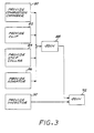
- FIG. 3 depicts a preferred approach for fabricating the rocket engine 20.
- the combustion chamber 22 is provided, numeral 80.
- the combustion chamber may be made of any operable material, but is preferably made of rhenium having a coating 65 of iridium, about 0.003-0.005 inches thick, on the inner cylindrical surface 32 to protect the rhenium from corrosion damage during service.
- the combustion chamber may be of any operable size and specific configuration.
- the nominal overall length of the combustion chamber 22 is about 3.7 inches
- the nominal diameter C i of the inner cylindrical surface 32 is about 1.780 inches
- the nominal diameter C o of the outer cylindrical surface 30 is about 1.910 inches (so that the thickness of the wall 24 is about 0.065 inches.
- the clip 58 is provided, numeral 82.
- the clip 58 may be made of any operable material, but is preferably made of an alloy of molybdenum-50 percent by weight rhenium, which is plated with a thin gold plating. This material has a strength that is several times greater than that of the rhenium material of the combustion chamber 22. With this greater strength, the clip 58 serves in the manner of a circumferential rib to carry the load produced by the differential thermal expansion of the step collar 46 during service, ensuring that minimal load is transferred to the wall 24 of the combustion chamber 22 as the step collar 46 expands upon heating in service.
- pertinent nominal dimensions of the clip 58 are A i of 1.901 inches, A o of 1.738 inches, and A r of 1.571 inches. (The inner diameter of the first leg 60 is subsequently match machined to the outer diameter of the combustion chamber, so that there is a spacing of no more than about 0.005-0.006 between them.)
- the step collar 46 is provided, numeral 84.
- the step collar 46 may be made of any operable material having sufficient oxidation and erosion resistance, but is preferably made of a refractory material such as an alloy of platinum and rhodium, or an alloy of columbium.
- the preferred alloy of platinum and rhodium is 90 percent by weight platinum, balance rhodium.
- the preferred alloy of columbium is 10 percent by weight hafnium, 1 percent by weight titanium, balance columbium.
- the preferred ceramic is aluminum oxide, thorium oxide, or yttria-stabilized zirconium oxide.
- the pertinent nominal dimensions are S i of 1.402 inches, S maxo of 1.740 inches, S mino of 1.563 inches, and S a /W a about 0.28.
- the adaptor 52 is provided, numeral 86.
- the adaptor is preferably made of titanium, most preferably an alloy of 6 weight percent aluminum, 4 weight percent vanadium, balance titanium so as to be compatible with the injector 38.
- the combustion chamber 22, the adaptor 52, the step collar 46, and the clip 58 are joined together, numeral 88.
- the joining is preferably accomplished by brazing using known operable braze alloys for the particular materials to be joined.
- the combustion chamber 22, the adaptor 52, the step collar 46, and the clip 58 are assembled together as subassemblies with a thin shim of braze alloy between the adaptor 52 and the step collar 46, another thin shim of braze alloy between the step collar 46 and the second leg 62 of the clip 58, and another thin shim of braze alloy between the outer cylindrical surface 30 of the wall 24 and the first leg 60 of the clip 58.
- the subassemblies, held together in tooling, are heated to appropriate brazing temperatures to melt the braze alloy.
- the assembly is then cooled so that the braze alloy solidifies and bonds the combustion chamber 22, the adaptor 52, the step collar 46, and the clip 58 into a single subassembly.
- the clip 58, and the step collar 46 care is taken so that there is no contact between any gold plating on the clip 58 and the iridium coating 65 of the combustion chamber.
- care is taken so that there is no contact between any gold plating on the clip 58 and the iridium coating 65 of the combustion chamber.
- the gap 64 ensures that there is no contact between the gold coating on the second leg 62 of the clip 58 and the iridium coating 65.
- the gold coating on the clip 58 is preferably machined away from a trough region 67 on the inside curvature of the web 63, to ensure that there can be no contact between gold in that region and the iridium coating 65.
- the injector plate 38 is provided, numeral 90.
- the injector plate 38 is typically made of titanium, most preferably an alloy of 6 weight percent aluminum, 4 weight percent vanadium, balance titanium.
- the injector plate 38 is joined to the adaptor 52, numeral 92, preferably by electron beam welding.
- a rocket engine made according to the preferred approach has been constructed and tested.
- the rocket engine had a specific impulse of 324 seconds, as compared with a specific impulse of 315 seconds for a rocket engine that is otherwise similar but lacks the internal step collar.
Landscapes
- Engineering & Computer Science (AREA)
- Chemical & Material Sciences (AREA)
- Combustion & Propulsion (AREA)
- Mechanical Engineering (AREA)
- General Engineering & Computer Science (AREA)
- Testing Of Engines (AREA)
- Combustion Methods Of Internal-Combustion Engines (AREA)
Abstract
Description
Claims (7)
- A rocket engine, comprising
a combustion chamber (22) having a generally cylindrical annular upper wall (24) with a chamber outer diameter, a chamber inner diameter, the chamber having an injector end (34) and a nozzle end (36); and
an injector (38) attached to the injector end (34) of the combustion chamber (22), characterized by
a generally cylindrical annular step collar (46) fitting within the combustion chamber (22) adjacent to the injector end (34) thereof, the step collar (46) having a step collar length measured from the nozzle end (36) of the combustion chamber of from about 21 percent to about 31 percent of a chamber length measured from the injector end to a throat (29) of the nozzle (28); and
an attachment (48) of the combustion chamber (22), the injector (38), and the step collar (46). - The rocket engine of claim 1, characterized in that the combustion chamber (22) is made of a first material, and the step collar (46) is made of a second material different from the first material and having a greater corrosion and erosion resistance in a combustion chamber operating environment.
- A rocket engine, comprising
a combustion chamber (22) having a generally cylindrical annular upper wall (24) with a chamber outer diameter, a chamber inner diameter, and a chamber length, the chamber (22) having an injector end (34) and a nozzle end (36);
an injector (38) attached to the injector end (34) of the combustion chamber (22);
a generally cylindrical annular step collar (46) fitting within the combustion chamber (22) adjacent to the injector end (34) thereof, the step collar (46) having a step collar outer diameter, a step collar inner diameter, and a step collar length measured from the nozzle end (36) of the combustion chamber (22) of less than the chamber length, wherein the combustion chamber (22) is made of a first material, and the step collar is made of a second material different from the first material and having a greater corrosion and erosion resistance in a combustion chamber operating environment; and
an attachment of the combustion chamber, the injector, and the step collar. - The rocket engine of claim 3, characterized in that the step collar maximum outer diameter is less than the chamber inner diameter by an amount of from about 0.020 inches (0.0508 cm) to about 0.024 inches (0.061 cm), measured at room temperature.
- The rocket engine of claim 3 or 4, characterized in that the length of the step collar (46) is from about 21 to about 31 percent of the chamber length.
- The rocket engine of any of claims 1-5, characterized in that the step collar (46) is made of a material selected from the group consisting of an alloy of platinum and rhodium, an alloy of columbium, and a ceramic.
- The rocket engine of any of claims 1-6, characterized in that the attachment (46) comprises:a step collar/injector joint structure (50) joining the step collar (46) and the injector (38); anda clip structure (56) joining the combustion chamber (22) and the step collar (46), the clip structure (56) comprising a C-shaped annular clip (58) having
a first leg (60) extending parallel to the chamber length and with an inner diameter of about that of the outer diameter of the combustion chamber and affixed thereto,
a second leg (62) extending parallel to the chamber length and with an outer diameter of no greater than that of the outer diameter of the step collar and affixed thereto, and
a web (63) extending between the first leg (60) and the second leg (62).
Applications Claiming Priority (3)
| Application Number | Priority Date | Filing Date | Title |
|---|---|---|---|
| US5759397P | 1997-08-29 | 1997-08-29 | |
| EP98116168A EP0899447B1 (en) | 1997-08-29 | 1998-08-27 | Attachment ring for a rocket combustion chamber |
| US57593 | 2002-01-25 |
Related Parent Applications (2)
| Application Number | Title | Priority Date | Filing Date |
|---|---|---|---|
| EP98116168A Division EP0899447B1 (en) | 1997-08-29 | 1998-08-27 | Attachment ring for a rocket combustion chamber |
| EP98116168.0 Division | 1998-08-27 |
Publications (3)
| Publication Number | Publication Date |
|---|---|
| EP1357282A2 true EP1357282A2 (en) | 2003-10-29 |
| EP1357282A3 EP1357282A3 (en) | 2005-09-14 |
| EP1357282B1 EP1357282B1 (en) | 2010-04-28 |
Family
ID=28793244
Family Applications (1)
| Application Number | Title | Priority Date | Filing Date |
|---|---|---|---|
| EP03016952A Expired - Lifetime EP1357282B1 (en) | 1997-08-29 | 1998-08-27 | Rocket engine with internal chamber step structure |
Country Status (1)
| Country | Link |
|---|---|
| EP (1) | EP1357282B1 (en) |
Cited By (2)
| Publication number | Priority date | Publication date | Assignee | Title |
|---|---|---|---|---|
| CN104061089A (en) * | 2014-05-18 | 2014-09-24 | 西北工业大学 | Device and method for testing solid fuel melting characteristics |
| CN110761918A (en) * | 2019-11-08 | 2020-02-07 | 猫头鹰安防科技有限公司 | A low-cost and practical fire extinguishing bomb power device ignition system |
Family Cites Families (2)
| Publication number | Priority date | Publication date | Assignee | Title |
|---|---|---|---|---|
| GB749670A (en) * | 1952-02-11 | 1956-05-30 | Mini Of Supply | Improvements in or relating to jet reaction motors |
| US4936091A (en) * | 1988-03-24 | 1990-06-26 | Aerojet General Corporation | Two stage rocket combustor |
-
1998
- 1998-08-27 EP EP03016952A patent/EP1357282B1/en not_active Expired - Lifetime
Cited By (3)
| Publication number | Priority date | Publication date | Assignee | Title |
|---|---|---|---|---|
| CN104061089A (en) * | 2014-05-18 | 2014-09-24 | 西北工业大学 | Device and method for testing solid fuel melting characteristics |
| CN104061089B (en) * | 2014-05-18 | 2017-01-04 | 西北工业大学 | A kind of solid fuel melting characteristic test device and method of testing |
| CN110761918A (en) * | 2019-11-08 | 2020-02-07 | 猫头鹰安防科技有限公司 | A low-cost and practical fire extinguishing bomb power device ignition system |
Also Published As
| Publication number | Publication date |
|---|---|
| EP1357282B1 (en) | 2010-04-28 |
| EP1357282A3 (en) | 2005-09-14 |
Similar Documents
| Publication | Publication Date | Title |
|---|---|---|
| US6269630B1 (en) | Rocket engine with internal chamber step structure | |
| EP0899449B1 (en) | Rocket engine having a transition attachment between a combustion chamber and an injector | |
| EP0899448B1 (en) | Fabrication of a rocket engine with transition structure between the combustion chamber and the injector | |
| US10767497B2 (en) | Turbine vane assembly with ceramic matrix composite components | |
| US5392596A (en) | Combustor assembly construction | |
| EP0780563A2 (en) | Rocket thrust chamber | |
| EP1777461B1 (en) | Attachement of a ceramic combustor can | |
| US8230673B2 (en) | Rocket engine injectorhead with flashback barrier | |
| US6138451A (en) | Rocket engine with combustion chamber step structure insert, and its fabrication | |
| Schneider | High temperature thruster technology for spacecraft propulsion | |
| US6079101A (en) | Rocket engine with one-piece combustion chamber step structure, and its fabrication | |
| Schoenman | 4000 F materials for low-thrust rocket engines | |
| EP1357282B1 (en) | Rocket engine with internal chamber step structure | |
| RU2220313C2 (en) | Rocket engine chamber housing | |
| US6138450A (en) | Rocket engine with integral combustion chamber step structure and its fabrication | |
| US8572946B2 (en) | Microfluidic flame barrier | |
| Reed et al. | Iridium-coated rhenium radiation-cooled rockets | |
| US20120279197A1 (en) | Nitrous oxide flame barrier | |
| JP4946295B2 (en) | Thruster | |
| Tuffias et al. | Engineering issues of iridium/rhenium rocket engines revisited | |
| Schulte | High performance 400N MMH/NTO bipropellant engine for apogee boost maneuvers | |
| EP3537046B1 (en) | Dual wall liner for a gas turbine engine | |
| Nandiga et al. | Design, Fabrication and Testing of Extended Life Space Shuttle Vernier Engines | |
| Jassowski et al. | Advanced small rocket chambers: Option 1, 14 lbf Ir-Re rocket | |
| WOOD | Development experience with 22N bipropellant thrusters using columbium and rhenium thrust chambers |
Legal Events
| Date | Code | Title | Description |
|---|---|---|---|
| PUAI | Public reference made under article 153(3) epc to a published international application that has entered the european phase |
Free format text: ORIGINAL CODE: 0009012 |
|
| 17P | Request for examination filed |
Effective date: 20030725 |
|
| AC | Divisional application: reference to earlier application |
Ref document number: 0899447 Country of ref document: EP Kind code of ref document: P |
|
| AK | Designated contracting states |
Kind code of ref document: A2 Designated state(s): DE FR GB |
|
| RIN1 | Information on inventor provided before grant (corrected) |
Inventor name: NEIDERMAN, JOEL Inventor name: BRONSON, DAVID Inventor name: WOLL, PETER Inventor name: STECHMANN, CARL R. Inventor name: KREINER, KURT B. |
|
| RIN1 | Information on inventor provided before grant (corrected) |
Inventor name: WOLL, PETER Inventor name: BRONSON, DAVID Inventor name: NEIDERMAN, JOEL Inventor name: STECHMANN, CARL R. Inventor name: KREINER, KURT B. |
|
| PUAL | Search report despatched |
Free format text: ORIGINAL CODE: 0009013 |
|
| AK | Designated contracting states |
Kind code of ref document: A3 Designated state(s): DE FR GB |
|
| RIC1 | Information provided on ipc code assigned before grant |
Ipc: 7F 02K 9/52 B Ipc: 7F 02K 9/62 A Ipc: 7B 23P 15/00 B Ipc: 7F 02K 9/60 B |
|
| AKX | Designation fees paid |
Designated state(s): DE FR GB |
|
| 17Q | First examination report despatched |
Effective date: 20060725 |
|
| GRAP | Despatch of communication of intention to grant a patent |
Free format text: ORIGINAL CODE: EPIDOSNIGR1 |
|
| GRAS | Grant fee paid |
Free format text: ORIGINAL CODE: EPIDOSNIGR3 |
|
| GRAA | (expected) grant |
Free format text: ORIGINAL CODE: 0009210 |
|
| AC | Divisional application: reference to earlier application |
Ref document number: 0899447 Country of ref document: EP Kind code of ref document: P |
|
| AK | Designated contracting states |
Kind code of ref document: B1 Designated state(s): DE FR GB |
|
| REG | Reference to a national code |
Ref country code: GB Ref legal event code: FG4D |
|
| REF | Corresponds to: |
Ref document number: 69841644 Country of ref document: DE Date of ref document: 20100610 Kind code of ref document: P |
|
| PLBE | No opposition filed within time limit |
Free format text: ORIGINAL CODE: 0009261 |
|
| STAA | Information on the status of an ep patent application or granted ep patent |
Free format text: STATUS: NO OPPOSITION FILED WITHIN TIME LIMIT |
|
| 26N | No opposition filed |
Effective date: 20110131 |
|
| REG | Reference to a national code |
Ref country code: FR Ref legal event code: PLFP Year of fee payment: 19 |
|
| REG | Reference to a national code |
Ref country code: FR Ref legal event code: PLFP Year of fee payment: 20 |
|
| PGFP | Annual fee paid to national office [announced via postgrant information from national office to epo] |
Ref country code: DE Payment date: 20170829 Year of fee payment: 20 Ref country code: GB Payment date: 20170829 Year of fee payment: 20 Ref country code: FR Payment date: 20170825 Year of fee payment: 20 |
|
| REG | Reference to a national code |
Ref country code: DE Ref legal event code: R071 Ref document number: 69841644 Country of ref document: DE |
|
| REG | Reference to a national code |
Ref country code: GB Ref legal event code: PE20 Expiry date: 20180826 |
|
| PG25 | Lapsed in a contracting state [announced via postgrant information from national office to epo] |
Ref country code: GB Free format text: LAPSE BECAUSE OF EXPIRATION OF PROTECTION Effective date: 20180826 |