EP1357271A2 - Heat exchanger drain assembly having a frangible wall - Google Patents
Heat exchanger drain assembly having a frangible wall Download PDFInfo
- Publication number
- EP1357271A2 EP1357271A2 EP20030075967 EP03075967A EP1357271A2 EP 1357271 A2 EP1357271 A2 EP 1357271A2 EP 20030075967 EP20030075967 EP 20030075967 EP 03075967 A EP03075967 A EP 03075967A EP 1357271 A2 EP1357271 A2 EP 1357271A2
- Authority
- EP
- European Patent Office
- Prior art keywords
- drain port
- set forth
- wall
- reservoir
- frangible
- Prior art date
- Legal status (The legal status is an assumption and is not a legal conclusion. Google has not performed a legal analysis and makes no representation as to the accuracy of the status listed.)
- Granted
Links
- 239000012530 fluid Substances 0.000 claims abstract description 61
- 238000005192 partition Methods 0.000 claims description 12
- 239000004677 Nylon Substances 0.000 claims description 5
- 229920001778 nylon Polymers 0.000 claims description 5
- 239000000463 material Substances 0.000 claims description 3
- 239000002826 coolant Substances 0.000 description 19
- 239000002184 metal Substances 0.000 description 5
- 239000004033 plastic Substances 0.000 description 4
- 230000007797 corrosion Effects 0.000 description 2
- 238000005260 corrosion Methods 0.000 description 2
- 238000009434 installation Methods 0.000 description 1
- 238000004519 manufacturing process Methods 0.000 description 1
- 238000012986 modification Methods 0.000 description 1
- 230000004048 modification Effects 0.000 description 1
Images

Classifications
-
- F—MECHANICAL ENGINEERING; LIGHTING; HEATING; WEAPONS; BLASTING
- F16—ENGINEERING ELEMENTS AND UNITS; GENERAL MEASURES FOR PRODUCING AND MAINTAINING EFFECTIVE FUNCTIONING OF MACHINES OR INSTALLATIONS; THERMAL INSULATION IN GENERAL
- F16K—VALVES; TAPS; COCKS; ACTUATING-FLOATS; DEVICES FOR VENTING OR AERATING
- F16K51/00—Other details not peculiar to particular types of valves or cut-off apparatus
-
- F—MECHANICAL ENGINEERING; LIGHTING; HEATING; WEAPONS; BLASTING
- F01—MACHINES OR ENGINES IN GENERAL; ENGINE PLANTS IN GENERAL; STEAM ENGINES
- F01P—COOLING OF MACHINES OR ENGINES IN GENERAL; COOLING OF INTERNAL-COMBUSTION ENGINES
- F01P11/00—Component parts, details, or accessories not provided for in, or of interest apart from, groups F01P1/00 - F01P9/00
- F01P11/02—Liquid-coolant filling, overflow, venting, or draining devices
- F01P11/0276—Draining or purging
-
- F—MECHANICAL ENGINEERING; LIGHTING; HEATING; WEAPONS; BLASTING
- F16—ENGINEERING ELEMENTS AND UNITS; GENERAL MEASURES FOR PRODUCING AND MAINTAINING EFFECTIVE FUNCTIONING OF MACHINES OR INSTALLATIONS; THERMAL INSULATION IN GENERAL
- F16K—VALVES; TAPS; COCKS; ACTUATING-FLOATS; DEVICES FOR VENTING OR AERATING
- F16K13/00—Other constructional types of cut-off apparatus; Arrangements for cutting-off
- F16K13/04—Other constructional types of cut-off apparatus; Arrangements for cutting-off with a breakable closure member
-
- F—MECHANICAL ENGINEERING; LIGHTING; HEATING; WEAPONS; BLASTING
- F01—MACHINES OR ENGINES IN GENERAL; ENGINE PLANTS IN GENERAL; STEAM ENGINES
- F01P—COOLING OF MACHINES OR ENGINES IN GENERAL; COOLING OF INTERNAL-COMBUSTION ENGINES
- F01P2070/00—Details
-
- Y—GENERAL TAGGING OF NEW TECHNOLOGICAL DEVELOPMENTS; GENERAL TAGGING OF CROSS-SECTIONAL TECHNOLOGIES SPANNING OVER SEVERAL SECTIONS OF THE IPC; TECHNICAL SUBJECTS COVERED BY FORMER USPC CROSS-REFERENCE ART COLLECTIONS [XRACs] AND DIGESTS
- Y10—TECHNICAL SUBJECTS COVERED BY FORMER USPC
- Y10T—TECHNICAL SUBJECTS COVERED BY FORMER US CLASSIFICATION
- Y10T137/00—Fluid handling
- Y10T137/1624—Destructible or deformable element controlled
- Y10T137/1632—Destructible element
- Y10T137/1692—Rupture disc
Definitions
- the subject invention relates to a heat exchanger drain assembly for selectively draining a fluid from the heat exchanger.
- Heat exchangers such as automotive radiators, include a heat transfer area having a plurality of tubes and corrugated fins and a manifold mounted to each end of the heat transfer area. Fluid, such as radiator coolant, flows through the tubes and manifolds to facilitate an exchange of heat to reduce the temperature of the fluid. At times, the radiator coolant is replaced.
- a drain port is typically provided at the bottom of one of the manifolds.
- a plug is disposed in the drain port wherein the plug may be removed, or partially removed, to open the drain port and allow the fluid to flow out of the radiator.
- U.S. Patent No. 4,193,575 discloses a radiator drain assembly having a partially removable plug. Alternatively, an outlet hose, which is connected to one of the manifolds, can be detached which allows the radiator coolant to flow out of the radiator. Hence, during certain situations the coolant can be removed from the radiator without the use of the drain port.
- Radiator manifolds have been traditionally made of metal with an internally threaded drain port.
- the plug has a number of seals and external threads which mate with the internal threads of the drain port.
- the plug and drain port interconnection is often plagued with parts that leak when initially assembled as well as leaks at the vehicle installation stage. Further, this interconnection is prone to failure due to corrosion of the metal parts over time. Often times a corroded plug cannot be easily released or cannot be removed without causing permanent damage to the radiator.
- the manifolds of automotive radiators have been formed of plastic so as to reduce the weight of the radiator and the cost of manufacture. In addition, these plastic manifolds are not subject to corrosion damage.
- radiator coolants have been improved such that these coolants have a long service life and may not require changing during operable life of the vehicle.
- the drain port and plug leakage is particularly bothersome in that the plug and coolant must be replaced even though the coolant is within its operable life.
- a heat exchanger having a heat exchanger drain assembly comprising a manifold or tank defining a reservoir for storing fluid therein.
- a drain port is mounted to the manifold and is in selective fluid communication with the reservoir for selectively draining the fluid from the manifold.
- a plug is selectively disposed within the drain port for preventing fluid from draining from the manifold and being removable from the drain port for allowing fluid to drain from the manifold.
- a frangible wall is disposed between the drain port and the reservoir to close the drain port and prevent fluid communication between the drain port and the reservoir. The frangible wall is fracturable to provide the fluid communication between the drain port and the reservoir for draining the fluid from the tank.
- the subject invention provides a heat exchanger with a non-functioning drain port to ensure leak free use for the life of the radiator.
- the subject invention incorporates a frangible wall which can be fractured to allow a fluid, such as radiator coolant, to flow out of the radiator.
- a heat exchanger is generally shown at 10 in Figure 1.
- the heat exchanger 10 is preferably a radiator for a vehicle such as an automobile.
- Heat exchangers 10 of this type include a pair of opposing manifolds 12 or tanks 12.
- the manifolds 12 have walls 14 which define chambers for retaining fluid therein.
- These manifolds 12 or tanks 12 may be of any suitable design or configuration.
- a plurality of metal tubes 16 interconnect the manifolds 12 and are in fluid communication with the chambers.
- a plurality of metal corrugated fins 18 interconnect the tubes 16 as is known in the heat exchanger 10 art.
- a drain port 20 is mounted to one of the manifolds 12 and is in selective fluid communication with the chamber for selectively draining the fluid from the manifold 12, which in turn drains the fluid from the heat exchanger 10. It should be appreciated that the subject invention may be satisfactorily used in other heat exchangers of any design without deviating from the scope of the subject invention.
- the manifold 12 or tank 12 of the subject invention is preferably formed of polymeric or nylon material.
- the heat exchanger 10 includes a metal mounting face 22 which clasps the nylon manifold 12 to secure the manifold 12 to the remaining portions of the heat exchanger 10.
- the manifold 12 includes a substantially continuous exterior wall 14 defining the fluid chamber.
- a mounting flange 24 and an inlet pipe 26 are integrally formed with the exterior wall 14 of the nylon manifold 12.
- the heat exchanger 10 has a heat exchanger drain assembly 28 which includes the drain port 20 integrally formed with the exterior wall 14.
- the drain port 20 has an internally threaded bore 30.
- the heat exchanger drain assembly 28 also includes a plug 32 being selectively disposed within the drain port 20 for preventing fluid from draining from the manifold 12.
- the plug 32 is removable from the drain port 20 for allowing fluid to drain from the manifold 12 as is known in the art.
- the plug 32 includes a series of external threads 34 which correspond to the threaded bore 30 such that the plug 32 is threadingly engageable with the drain port 20.
- the fluid chamber includes a reservoir 36 disposed at a bottom basin 38 of the chamber.
- the exterior wall 14 of the manifold 12 defines both the chamber and the reservoir 36.
- the reservoir 36 is in selective fluid communication with the drain port 20 as will be discussed in greater detail below.
- a frangible wall 40 is disposed between the drain port 20 and the reservoir 36 to close the drain port 20 and prevent fluid communication between the drain port 20 and the reservoir 36.
- the exterior wall 14 is continuous across, or flashed over, the drain port 20 for closing the drain port 20 from the reservoir 36.
- the frangible wall 40 creates a non-functioning drain port 20.
- the radiator coolant may never be changed during the operable life of the vehicle.
- the coolant can be removed from the radiator without using the drain port 20.
- the subject invention provides a non-functioning drain port 20 that ensures a leak tight drain port 20.
- the frangible wall 40 is fracturable to provide the fluid communication between the drain port 20 and the reservoir 36 for draining the fluid from the manifold 12 such as shown in Figures 2 and 3.
- the manifold 12 or tank 12 includes at least one groove 42 defining the frangible wall 40 with the groove 42 providing a weakened section within the manifold 12 to facilitate the fracturability of the frangible wall 40.
- the groove 42 is formed within the exterior wall 14 to define the frangible wall 40 aligned with the drain port 20.
- the exterior wall 14 includes inner 46 and outer 48 surfaces and the groove 42 is formed within the outer surface 48 facing the drain port 20 to provide a smooth inner surface 46 facing the reservoir 36.
- the groove 42 is substantially continuous and defines a perimeter of the frangible wall 40.
- the exterior wall 14 and the frangible wall 40 are of substantially the same thickness. It should be appreciated that the frangible wall 40 may be of any suitable wall thickness so long as the reservoir 36 is sealed from the drain port 20.
- the groove 42 is illustrated as a continuous annular notch which creates a convex surface on the frangible wall 40.
- a tool is used to fracture the frangible wall 40.
- the tool can be of any suitable design or configuration and can be threaded into the drain port 20.
- the tool is the plug 32 having an engagement portion 50 for selectively engaging the frangible wall 40 to fracture the frangible wall 40.
- the plug 32 includes an abutment 52 which aligns with the frangible wall 40 when the plug 32 is disposed within the drain port 20 once the frangible wall 40 is completely fractured.
- the abutment 52 of the plug 32 engages the frangible wall 40 to fracture the frangible wall 40 about the groove 42 from the exterior wall 14.
- the plug 32 is threadingly engaged with the drain port 20.
- the plug 32 is threaded, either manually or by use of a wrench or similar device, toward the frangible wall 40.
- the abutment 52 first engages the frangible wall 40 and then applies sufficient force to fracture the frangible wall 40 about the groove 42, see Figure 2.
- an aperture 54 is created within the exterior wall 14 aligned with the drain port 20 once the frangible wall 40 is completely fractured.
- the bottom basin 38 captures the frangible wall 40 when the frangible wall 40 separates from the exterior wall 14.
- the frangible wall 40 is harmlessly trapped in the reservoir 36 because the frangible wall 40 is larger than the size of the tubes 16 extending between the manifolds 12.
- the plug 32 may then be removed from the drain port 20 and the coolant within the manifold 12 can flow out of the reservoir 36 through the aperture 54 and drain port 20.
- the plug 32 may subsequently be threaded back into the drain port 20 to seal the aperture 54 and re-seal the drain port 20 such that the heat exchanger 10 may be refilled with coolant.
- the heat exchanger drain assembly 28 of this embodiment also includes the fluid chamber having a reservoir 36 disposed at a bottom basin 38 of the chamber.
- the frangible wall 40 is disposed between the drain port 20 and the reservoir 36 to close the drain port 20 and prevent fluid communication between the drain port 20 and the reservoir 36.
- the exterior wall 14 is continuous across, or flashed over, the drain port 20 for closing the drain port 20 from the reservoir 36.
- the frangible wall 40 creates a non-functioning drain port 20 that ensures a leak tight drain port 20.
- the frangible wall 40 is fracturable to provide the fluid communication between the drain port 20 and the reservoir 36 for draining the fluid from the manifold 12 such as shown in Figures 4 and 5.
- the frangible wall 40 includes the groove 42 providing a weakened section within the manifold 12 to facilitate the fracturability of the frangible wall 40.
- the exterior wall 14 includes inner 46 and outer 48 surfaces and the groove 42 is formed within the outer surface 48 facing the drain port 20 to provide a smooth inner surface 46 facing the reservoir 36.
- the groove 42 is a continuous annular notch which defines a perimeter of the frangible wall 40.
- the frangible wall 40 also includes a projection 56 extending into the drain port 20.
- the projection 56 is a smooth post extending centrally from the frangible wall 40.
- a tool is used to fracture the frangible wall 40.
- the tool can be of any suitable design or configuration and can be threaded into the drain port 20.
- the tool is the plug 32 having an engagement portion 50 for selectively engaging the frangible wall 40 to fracture the frangible wall 40.
- the plug 32 is threadingly engaged with the drain port 20.
- the plug 32 includes a grasping portion 58 engaging at least a portion 50 of the projection 56 to interlock the plug 32 and the frangible wall 40 when the plug 32 engages the frangible wall 40 such as shown in Figure 4.
- the frangible wall 40 is removed from the drain port 20 in conjunction with a removal of the plug 32.
- the plug 32 is threaded, either manually or by use of a wrench or similar device, toward the frangible wall 40.
- the grasping portion 58 engages the projection 56 and the engagement portion 50 abuts the groove 42 of the frangible wall 40.
- the grasping portion 58 is frictionally press-fit to the projection 56.
- Sufficient force is then applied to fracture the frangible wall 40 about the groove 42, see Figure 4.
- an aperture 54 is created within the exterior wall 14 as the plug 32 is removed from the drain port 20 with the frangible wall 40 being secured thereto.
- the coolant within the manifold 12 can flow out of the reservoir 36 through the aperture 54 and drain port 20.
- the plug 32 may subsequently be threaded back into the drain port 20, preferably without the frangible wall, to seal the aperture 54 and re-seal the drain port 20 such that the heat exchanger 10 may be refilled with coolant.
- the heat exchanger drain assembly 28 of this embodiment also includes the fluid chamber having a reservoir 36 disposed at a bottom basin 38 of the chamber.
- the frangible wall 40 is disposed between the drain port 20 and the reservoir 36 to close the drain port 20 and prevent fluid communication between the drain port 20 and the reservoir 36.
- the exterior wall 14 is continuous across, or flashed over, the drain port 20 for closing the drain port 20 from the reservoir 36.
- the frangible wall 40 creates a non-functioning drain port 20 that ensures a leak tight drain port 20.
- the frangible wall 40 is fracturable to provide the fluid communication between the drain port 20 and the reservoir 36 for draining the fluid from the manifold 12 such as shown in Figures 6 and 7.
- the frangible wall 40 includes the groove 42 providing a weakened section within the manifold 12 to facilitate the fracturability of the frangible wall 40.
- the exterior wall 14 includes inner 46 and outer 48 surfaces and the groove 42 is formed within the outer surface 48 facing the drain port 20 to provide a smooth inner surface 46 facing the reservoir 36.
- the frangible wall 40 of this alternative embodiment includes a projection 60 extending into the drain port 20. Preferably, the projection 60 is of a substantial width.
- Another unique feature of this alternative embodiment is a partition 62 which extends from the exterior wall 14 and preferably extends upwardly from the bottom basin 38.
- the partition 62 therefore divides the bottom basin 38.
- a tool is used to fracture the frangible wall 40.
- the tool can be of any suitable design or configuration and can be threaded into the drain port 20.
- the tool is the plug 32 having an engagement portion 50 for selectively engaging the frangible wall 40 to fracture the frangible wall 40.
- the plug 32 is threadingly engaged with the drain port 20.
- the engagement portion 50 of the plug 32 engages the projection 60 of the frangible wall 40 to fracture the frangible wall 40 such as shown in Figure 6.
- the frangible wall 40 is trapped between the drain port 20 and the partition 62 when the frangible wall 40 is fractured from the exterior wall 14.
- the plug 32 is threaded, either manually or by use of a wrench or similar device, toward the frangible wall 40.
- the engagement portion 50 abuts the projection 60 and sufficient force is then applied to fracture the frangible wall 40 about the groove 42, see Figure 6.
- an aperture 54 is created within the exterior wall 14 aligned with the drain port 20.
- the frangible wall 40 and projection 60 become trapped between the drain port 20 and the partition 62.
- the projection 60 rests on one side of the aperture 54 and a back side of the frangible wall 40 abuts the partition 62.
- the coolant within the manifold 12 can flow out of the reservoir 36 through the aperture 54 and drain port 20.
- the location of the partition 62 and the configuration of the projection 60 allows coolant to flow around the projection 60 instead of pushing the projection 60 and frangible wall 40 back into the aperture 54.
- the plug 32 may subsequently be threaded back into the drain port 20 to seal the aperture 54 and re-seal the drain port 20 such that the heat exchanger 10 may be refilled with coolant.
Landscapes
- Engineering & Computer Science (AREA)
- General Engineering & Computer Science (AREA)
- Mechanical Engineering (AREA)
- Chemical & Material Sciences (AREA)
- Combustion & Propulsion (AREA)
- Cooling, Air Intake And Gas Exhaust, And Fuel Tank Arrangements In Propulsion Units (AREA)
- Heat-Exchange Devices With Radiators And Conduit Assemblies (AREA)
Abstract
Description
- The subject invention relates to a heat exchanger drain assembly for selectively draining a fluid from the heat exchanger.
- Heat exchangers, such as automotive radiators, include a heat transfer area having a plurality of tubes and corrugated fins and a manifold mounted to each end of the heat transfer area. Fluid, such as radiator coolant, flows through the tubes and manifolds to facilitate an exchange of heat to reduce the temperature of the fluid. At times, the radiator coolant is replaced. A drain port is typically provided at the bottom of one of the manifolds. A plug is disposed in the drain port wherein the plug may be removed, or partially removed, to open the drain port and allow the fluid to flow out of the radiator. U.S. Patent No. 4,193,575 discloses a radiator drain assembly having a partially removable plug. Alternatively, an outlet hose, which is connected to one of the manifolds, can be detached which allows the radiator coolant to flow out of the radiator. Hence, during certain situations the coolant can be removed from the radiator without the use of the drain port.
- Radiator manifolds have been traditionally made of metal with an internally threaded drain port. The plug has a number of seals and external threads which mate with the internal threads of the drain port. The plug and drain port interconnection, however, is often plagued with parts that leak when initially assembled as well as leaks at the vehicle installation stage. Further, this interconnection is prone to failure due to corrosion of the metal parts over time. Often times a corroded plug cannot be easily released or cannot be removed without causing permanent damage to the radiator. Recently, the manifolds of automotive radiators have been formed of plastic so as to reduce the weight of the radiator and the cost of manufacture. In addition, these plastic manifolds are not subject to corrosion damage. An example of a radiator having a plastic manifold is disclosed in U.S. Patent No. 4,449,692. However, even with the plastic manifolds the plugs are prone to leakage, which creates unnecessary repair and replacement of the plug and/or radiator.
- In addition, radiator coolants have been improved such that these coolants have a long service life and may not require changing during operable life of the vehicle. Hence, the drain port and plug leakage is particularly bothersome in that the plug and coolant must be replaced even though the coolant is within its operable life.
- Accordingly, it would be desirable to develop a drain port and plug interconnection that is leak tight during initial assembly and vehicle assembly, and remains leak tight over time while still allowing selective draining of the manifold through the drain port when needed.
- A heat exchanger having a heat exchanger drain assembly comprising a manifold or tank defining a reservoir for storing fluid therein. A drain port is mounted to the manifold and is in selective fluid communication with the reservoir for selectively draining the fluid from the manifold. In the preferred embodiment, a plug is selectively disposed within the drain port for preventing fluid from draining from the manifold and being removable from the drain port for allowing fluid to drain from the manifold. A frangible wall is disposed between the drain port and the reservoir to close the drain port and prevent fluid communication between the drain port and the reservoir. The frangible wall is fracturable to provide the fluid communication between the drain port and the reservoir for draining the fluid from the tank.
- Accordingly, the subject invention provides a heat exchanger with a non-functioning drain port to ensure leak free use for the life of the radiator. In addition, the subject invention incorporates a frangible wall which can be fractured to allow a fluid, such as radiator coolant, to flow out of the radiator.
- Other advantages of the present invention will be readily appreciated as the same becomes better understood by reference to the following detailed description when considered in connection with the accompanying drawings wherein:
- Figure 1 is a fragmented perspective view of a heat exchanger incorporating the subject invention;
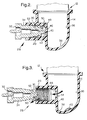
- Figure 2 is a cross-sectional view of a heat exchanger drain assembly with a plug disposed in a drain port for fracturing a frangible wall;
- Figure 3 is a cross-sectional view of the heat exchanger drain assembly of Figure 2 with the plug removed from the drain port and the frangible wall disposed in a bottom basin of a reservoir;
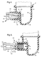
- Figure 4 is a cross-sectional view of an alternative embodiment of a heat exchanger drain assembly with a plug disposed in a drain port for fracturing a frangible wall;
- Figure 5 is a cross-sectional view of the heat exchanger drain assembly of Figure 4 with the plug and frangible wall removed from the drain port;
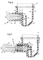
- Figure 6 is a cross-sectional view of another alternative embodiment of a heat exchanger drain assembly having a plug disposed in a drain port for fracturing a frangible wall; and
- Figure 7 is a cross-sectional view of the heat exchanger drain assembly of Figure 6 with the plug removed from the drain port and the frangible wall abutting a partition within a reservoir.
-
- Referring to the Figures, wherein like numerals indicate like or corresponding parts throughout the several views, a heat exchanger is generally shown at 10 in Figure 1. The
heat exchanger 10, as illustrated, is preferably a radiator for a vehicle such as an automobile.Heat exchangers 10 of this type include a pair ofopposing manifolds 12 ortanks 12. Themanifolds 12 havewalls 14 which define chambers for retaining fluid therein. Thesemanifolds 12 ortanks 12 may be of any suitable design or configuration. A plurality ofmetal tubes 16 interconnect themanifolds 12 and are in fluid communication with the chambers. In addition, a plurality of metalcorrugated fins 18 interconnect thetubes 16 as is known in theheat exchanger 10 art. Adrain port 20 is mounted to one of themanifolds 12 and is in selective fluid communication with the chamber for selectively draining the fluid from themanifold 12, which in turn drains the fluid from theheat exchanger 10. It should be appreciated that the subject invention may be satisfactorily used in other heat exchangers of any design without deviating from the scope of the subject invention. - The
manifold 12 ortank 12 of the subject invention is preferably formed of polymeric or nylon material. Theheat exchanger 10 includes ametal mounting face 22 which clasps thenylon manifold 12 to secure themanifold 12 to the remaining portions of theheat exchanger 10. Themanifold 12 includes a substantially continuousexterior wall 14 defining the fluid chamber. Amounting flange 24 and aninlet pipe 26 are integrally formed with theexterior wall 14 of thenylon manifold 12. - The
heat exchanger 10 has a heatexchanger drain assembly 28 which includes thedrain port 20 integrally formed with theexterior wall 14. Thedrain port 20 has an internally threadedbore 30. The heatexchanger drain assembly 28 also includes aplug 32 being selectively disposed within thedrain port 20 for preventing fluid from draining from themanifold 12. Theplug 32 is removable from thedrain port 20 for allowing fluid to drain from themanifold 12 as is known in the art. Theplug 32 includes a series ofexternal threads 34 which correspond to the threadedbore 30 such that theplug 32 is threadingly engageable with thedrain port 20. - Referring also to Figures 2 and 3, the heat
exchanger drain assembly 28 is shown in greater detail. In particular, the fluid chamber includes areservoir 36 disposed at abottom basin 38 of the chamber. Theexterior wall 14 of themanifold 12 defines both the chamber and thereservoir 36. Thereservoir 36 is in selective fluid communication with thedrain port 20 as will be discussed in greater detail below. - A
frangible wall 40 is disposed between thedrain port 20 and thereservoir 36 to close thedrain port 20 and prevent fluid communication between thedrain port 20 and thereservoir 36. Although not specifically illustrated, theexterior wall 14 is continuous across, or flashed over, thedrain port 20 for closing thedrain port 20 from thereservoir 36. Hence, thefrangible wall 40 creates anon-functioning drain port 20. As discussed in the background section, the radiator coolant may never be changed during the operable life of the vehicle. In addition, if the radiator coolant is to be replaced, the coolant can be removed from the radiator without using thedrain port 20. Hence, the subject invention provides anon-functioning drain port 20 that ensures a leaktight drain port 20. - In the event that the
drain port 20 must be utilized, thefrangible wall 40 is fracturable to provide the fluid communication between thedrain port 20 and thereservoir 36 for draining the fluid from the manifold 12 such as shown in Figures 2 and 3. Preferably, the manifold 12 ortank 12 includes at least onegroove 42 defining thefrangible wall 40 with thegroove 42 providing a weakened section within the manifold 12 to facilitate the fracturability of thefrangible wall 40. Thegroove 42 is formed within theexterior wall 14 to define thefrangible wall 40 aligned with thedrain port 20. In particular, theexterior wall 14 includes inner 46 and outer 48 surfaces and thegroove 42 is formed within theouter surface 48 facing thedrain port 20 to provide a smoothinner surface 46 facing thereservoir 36. Even more preferably, thegroove 42 is substantially continuous and defines a perimeter of thefrangible wall 40. - As shown in the embodiment of Figures 2 and 3, the
exterior wall 14 and thefrangible wall 40 are of substantially the same thickness. It should be appreciated that thefrangible wall 40 may be of any suitable wall thickness so long as thereservoir 36 is sealed from thedrain port 20. Thegroove 42 is illustrated as a continuous annular notch which creates a convex surface on thefrangible wall 40. - A tool is used to fracture the
frangible wall 40. The tool can be of any suitable design or configuration and can be threaded into thedrain port 20. Preferably, the tool is theplug 32 having anengagement portion 50 for selectively engaging thefrangible wall 40 to fracture thefrangible wall 40. In the embodiment of Figures 2 and 3, theplug 32 includes anabutment 52 which aligns with thefrangible wall 40 when theplug 32 is disposed within thedrain port 20 once thefrangible wall 40 is completely fractured. Theabutment 52 of theplug 32 engages thefrangible wall 40 to fracture thefrangible wall 40 about thegroove 42 from theexterior wall 14. As discussed above, theplug 32 is threadingly engaged with thedrain port 20. - During the fracturing of the
frangible wall 40, theplug 32 is threaded, either manually or by use of a wrench or similar device, toward thefrangible wall 40. Theabutment 52 first engages thefrangible wall 40 and then applies sufficient force to fracture thefrangible wall 40 about thegroove 42, see Figure 2. As shown in Figure 3, anaperture 54 is created within theexterior wall 14 aligned with thedrain port 20 once thefrangible wall 40 is completely fractured. Thebottom basin 38 captures thefrangible wall 40 when thefrangible wall 40 separates from theexterior wall 14. Thefrangible wall 40 is harmlessly trapped in thereservoir 36 because thefrangible wall 40 is larger than the size of thetubes 16 extending between the manifolds 12. Theplug 32 may then be removed from thedrain port 20 and the coolant within the manifold 12 can flow out of thereservoir 36 through theaperture 54 and drainport 20. Theplug 32 may subsequently be threaded back into thedrain port 20 to seal theaperture 54 and re-seal thedrain port 20 such that theheat exchanger 10 may be refilled with coolant. - Turning to Figures 4 and 5, an alternative embodiment of the heat
exchanger drain assembly 28 is shown. The heatexchanger drain assembly 28 of this embodiment also includes the fluid chamber having areservoir 36 disposed at abottom basin 38 of the chamber. Thefrangible wall 40 is disposed between thedrain port 20 and thereservoir 36 to close thedrain port 20 and prevent fluid communication between thedrain port 20 and thereservoir 36. As with the embodiment of Figures 2 and 3, theexterior wall 14 is continuous across, or flashed over, thedrain port 20 for closing thedrain port 20 from thereservoir 36. Hence, thefrangible wall 40 creates anon-functioning drain port 20 that ensures a leaktight drain port 20. - In the event that the
drain port 20 must be utilized, thefrangible wall 40 is fracturable to provide the fluid communication between thedrain port 20 and thereservoir 36 for draining the fluid from the manifold 12 such as shown in Figures 4 and 5. Thefrangible wall 40 includes thegroove 42 providing a weakened section within the manifold 12 to facilitate the fracturability of thefrangible wall 40. Theexterior wall 14 includes inner 46 and outer 48 surfaces and thegroove 42 is formed within theouter surface 48 facing thedrain port 20 to provide a smoothinner surface 46 facing thereservoir 36. Preferably, thegroove 42 is a continuous annular notch which defines a perimeter of thefrangible wall 40. Thefrangible wall 40 also includes aprojection 56 extending into thedrain port 20. Preferably, theprojection 56 is a smooth post extending centrally from thefrangible wall 40. - As with the primary embodiment, a tool is used to fracture the
frangible wall 40. The tool can be of any suitable design or configuration and can be threaded into thedrain port 20. Preferably, the tool is theplug 32 having anengagement portion 50 for selectively engaging thefrangible wall 40 to fracture thefrangible wall 40. As discussed above, theplug 32 is threadingly engaged with thedrain port 20. In the embodiment of Figures 4 and 5, theplug 32 includes a graspingportion 58 engaging at least aportion 50 of theprojection 56 to interlock theplug 32 and thefrangible wall 40 when theplug 32 engages thefrangible wall 40 such as shown in Figure 4. As shown in Figure 5, thefrangible wall 40 is removed from thedrain port 20 in conjunction with a removal of theplug 32. - During the fracturing of the
frangible wall 40 for this alternative embodiment, theplug 32 is threaded, either manually or by use of a wrench or similar device, toward thefrangible wall 40. The graspingportion 58 engages theprojection 56 and theengagement portion 50 abuts thegroove 42 of thefrangible wall 40. Preferably, the graspingportion 58 is frictionally press-fit to theprojection 56. Sufficient force is then applied to fracture thefrangible wall 40 about thegroove 42, see Figure 4. As shown in Figure 5, anaperture 54 is created within theexterior wall 14 as theplug 32 is removed from thedrain port 20 with thefrangible wall 40 being secured thereto. The coolant within the manifold 12 can flow out of thereservoir 36 through theaperture 54 and drainport 20. Theplug 32 may subsequently be threaded back into thedrain port 20, preferably without the frangible wall, to seal theaperture 54 and re-seal thedrain port 20 such that theheat exchanger 10 may be refilled with coolant. - Turning to Figures 6 and 7, another alternative embodiment of the heat
exchanger drain assembly 28 is shown. The heatexchanger drain assembly 28 of this embodiment also includes the fluid chamber having areservoir 36 disposed at abottom basin 38 of the chamber. Thefrangible wall 40 is disposed between thedrain port 20 and thereservoir 36 to close thedrain port 20 and prevent fluid communication between thedrain port 20 and thereservoir 36. As with the embodiments of Figures 2 through 5, theexterior wall 14 is continuous across, or flashed over, thedrain port 20 for closing thedrain port 20 from thereservoir 36. Hence, thefrangible wall 40 creates anon-functioning drain port 20 that ensures a leaktight drain port 20. - In the event that the
drain port 20 must be utilized, thefrangible wall 40 is fracturable to provide the fluid communication between thedrain port 20 and thereservoir 36 for draining the fluid from the manifold 12 such as shown in Figures 6 and 7. Thefrangible wall 40 includes thegroove 42 providing a weakened section within the manifold 12 to facilitate the fracturability of thefrangible wall 40. Theexterior wall 14 includes inner 46 and outer 48 surfaces and thegroove 42 is formed within theouter surface 48 facing thedrain port 20 to provide a smoothinner surface 46 facing thereservoir 36. Thefrangible wall 40 of this alternative embodiment includes aprojection 60 extending into thedrain port 20. Preferably, theprojection 60 is of a substantial width. - Another unique feature of this alternative embodiment is a
partition 62 which extends from theexterior wall 14 and preferably extends upwardly from thebottom basin 38. Thepartition 62 therefore divides thebottom basin 38. - As with the primary embodiment, a tool is used to fracture the
frangible wall 40. The tool can be of any suitable design or configuration and can be threaded into thedrain port 20. Preferably, the tool is theplug 32 having anengagement portion 50 for selectively engaging thefrangible wall 40 to fracture thefrangible wall 40. As discussed above, theplug 32 is threadingly engaged with thedrain port 20. In the embodiment of Figures 6 and 7, theengagement portion 50 of theplug 32 engages theprojection 60 of thefrangible wall 40 to fracture thefrangible wall 40 such as shown in Figure 6. As shown in Figure 7, thefrangible wall 40 is trapped between thedrain port 20 and thepartition 62 when thefrangible wall 40 is fractured from theexterior wall 14. - During the fracturing of the
frangible wall 40 for this alternative embodiment, theplug 32 is threaded, either manually or by use of a wrench or similar device, toward thefrangible wall 40. Theengagement portion 50 abuts theprojection 60 and sufficient force is then applied to fracture thefrangible wall 40 about thegroove 42, see Figure 6. As shown in Figure 7, anaperture 54 is created within theexterior wall 14 aligned with thedrain port 20. Thefrangible wall 40 andprojection 60 become trapped between thedrain port 20 and thepartition 62. In particular, theprojection 60 rests on one side of theaperture 54 and a back side of thefrangible wall 40 abuts thepartition 62. The coolant within the manifold 12 can flow out of thereservoir 36 through theaperture 54 and drainport 20. The location of thepartition 62 and the configuration of theprojection 60 allows coolant to flow around theprojection 60 instead of pushing theprojection 60 andfrangible wall 40 back into theaperture 54. Theplug 32 may subsequently be threaded back into thedrain port 20 to seal theaperture 54 and re-seal thedrain port 20 such that theheat exchanger 10 may be refilled with coolant. - Obviously, many modifications and variations of the present invention are possible in light of the above teachings and the invention may be practiced otherwise than as specifically described within the scope of the appended claims.
Claims (35)
- A heat exchanger drain assembly (28) comprising;
a tank (12) defining a reservoir (36) for storing fluid therein;
a drain port (20) mounted to said tank (12) and in selective fluid communication with said reservoir (36) for selectively draining the fluid from said tank (12);
a plug (32) selectively disposed within said drain port (20) for preventing fluid from draining from said tank (12) and being removable from said drain port (20) for allowing fluid to drain from said tank (12); and
a frangible wall (40) disposed between said drain port (20) and said reservoir (36) to close said drain port (20) and prevent fluid communication between said drain port (20) and said reservoir (36), said frangible wall (40) being fracturable to provide said fluid communication between said drain port (20) and said reservoir (36) for draining the fluid from said tank (12). - An assembly (28) as set forth in claim 1 wherein said tank (12) includes at least one groove (42) defining said frangible wall (40) with said groove (42) providing a weakened section within said tank (12) to facilitate said fracturability of said frangible wall (40).
- An assembly (28) as set forth in claim 2 wherein said groove (42) is substantially continuous and defines a perimeter of said frangible wall (40).
- An assembly (28) as set forth in claim 1 wherein said plug (32) includes an engagement portion (50) for selectively engaging said frangible wall (40) to fracture said frangible wall 40.
- An assembly (28) as set forth in claim 2 wherein said tank (12) includes an exterior wall (14) defining said reservoir (36).
- An assembly (28) as set forth in claim 5 wherein said exterior wall (14) is continuous across said drain port (20) for closing said drain port (20) from said reservoir (36) to prevent fluid communication between said drain port (20) and said reservoir (36) and said groove (42) is formed within said exterior wall (14) to define said frangible wall (40) aligned with said drain port (20).
- An assembly (28) as set forth in claim 6 wherein said exterior wall (14) includes inner (46) and outer (48) surfaces and said groove (42) is formed within said outer surface (48) facing said drain port (20) to provide a smooth inner surface (46) facing said reservoir (36).
- An assembly (28) as set forth in claim 5 wherein said exterior wall (14) and said frangible wall (40) are of substantially the same thickness.
- An assembly (28) as set forth in claim 8 wherein said plug (32) includes an abutment (52) which aligns with said frangible wall (40) when said plug (32) is disposed within said drain port (20) and engages said frangible wall (40) to fracture said frangible wall (40) from said exterior wall (14).
- An assembly (28) as set forth in claim 9 wherein said exterior wall (14) defines said reservoir (36) and a bottom basin (38) with said bottom basin (38) capturing said frangible wall (40) when said frangible wall (40) is fractured from said exterior wall (14).
- An assembly (28) as set forth in claim 5 wherein said frangible wall (40) includes a projection (56,60) extending into said drain port (20).
- An assembly (28) as set forth in claim 11 wherein said plug (32) includes an engagement portion (50) for selectively engaging said frangible wall (40) to fracture said frangible wall (40) from said exterior wall (14).
- An assembly (28) as set forth in claim 12 wherein said plug (32) includes a grasping portion (58) engaging at least a portion (50) of said projection (56) to interlock said plug (32) and said frangible wall (40) when said plug (32) engages said frangible wall (40) such that said frangible wall (40) is removed from said drain port (20) in conjunction with a removal of said plug (32).
- An assembly (28) as set forth in claim 5 further including a partition (62) extending from said exterior wall (14) into said reservoir (36) to trap said frangible wall (40) between said drain port (20) and said partition (62) when said frangible wall (40) is fractured from said exterior wall (14).
- An assembly (28) as set forth in claim 14 wherein said exterior wall (14) defines said reservoir (36) and a bottom basin (38) with said partition (62) extending upwardly from said bottom basin (38).
- An assembly (28) as set forth in claim 5 wherein said drain port (20) is integrally formed with said exterior wall (14).
- An assembly (28) as set forth in claim 16 wherein said drain port (20) includes an internally threaded bore (30).
- An assembly (28) as set forth in claim 17 wherein said plug (32) includes a series of external threads (34) which correspond to said threaded bore (30) such that said plug (32) is threadingly engageable with said drain port (20).
- An assembly (28) as set forth in claim 1 wherein said tank (12) is formed of a nylon material.
- An assembly (28) as set forth in claim 19 wherein said drain port (20) is integrally formed with said tank (12).
- A heat exchanger (10) comprising;
at least one manifold (12) having walls (14) defining a chamber for retaining fluid therein with a reservoir (36) disposed at a bottom of said chamber;
a plurality of tubes (16) connected to said manifold (12) and in fluid communication with said chamber;
a plurality of corrugated fins (18) interconnecting said tubes (16);
a drain port (20) mounted to said manifold (12) and in selective fluid communication with said reservoir (36) for selectively draining the fluid from said manifold (12); and
a frangible wall (40) disposed between said drain port (20) and said reservoir (36) to close said drain port (20) and prevent fluid communication between said drain port (20) and said reservoir (36), said frangible wall (40) being fracturable to provide said fluid communication between said drain port (20) and said reservoir (36) for draining the fluid from said manifold (12). - A heat exchanger (10) as set forth in claim 21 wherein said manifold (12) includes at least one groove (42) defining said frangible wall (40) with said groove (42) providing a weakened section within said manifold (12) to facilitate said fracturability of said frangible wall (40).
- A heat exchanger (10) as set forth in claim 22 wherein said groove (42) is substantially continuous and defines a perimeter of said frangible wall (40).
- A heat exchanger (10) as set forth in claim 21 further including a plug (32) selectively disposed within said drain port (20) for preventing fluid from draining from said manifold (12) and being removable from said drain port (20) for allowing fluid to drain from said manifold (12).
- A heat exchanger (10) as set forth in claim 24 wherein said plug (32) includes an engagement portion (50) for selectively engaging said frangible wall (40) to fracture said frangible wall (40).
- A heat exchanger (10) as set forth in claim 22 wherein said manifold (12) includes an exterior wall (14) defining said reservoir (36).
- A heat exchanger (10) as set forth in claim 26 wherein said exterior wall (14) is continuous across said drain port (20) for closing said drain port (20) from said reservoir (36) to prevent fluid communication between said drain port (20) and said reservoir (36) and said groove (42) is formed within said exterior wall (14) to define said frangible wall (40) aligned with said drain port (20).
- A heat exchanger (10) as set forth in claim 27 wherein said exterior wall (14) includes inner (46) and outer (48) surfaces and said groove (42) is formed within said outer surface (48) facing said drain port (20) to provide a smooth inner surface (46) facing said reservoir (36).
- A heat exchanger (10) as set forth in claim 26 wherein said exterior wall (14) and said frangible wall (40) are of substantially the same thickness.
- A heat exchanger (10) as set forth in claim 26 wherein said exterior wall (14) defines said reservoir (36) and a bottom basin (38) with said bottom basin (38) capturing said frangible all when said frangible wall (40) is fractured from said exterior wall (14).
- A heat exchanger (10) as set forth in claim 26 wherein said frangible wall (40) includes a projection (56,60) extending into said drain port (20).
- A heat exchanger (10) as set forth in claim 26 further including a partition (62) extending from said exterior wall (14) into said reservoir (36) to trap said frangible wall (40) between said drain port (20) and said partition (62) when said frangible wall (40) is fractured from said exterior wall (14).
- A heat exchanger (10) as set forth in claim 26 wherein said drain port (20) is integrally formed with said exterior wall (14).
- A heat exchanger (10) as set forth in claim 21 wherein said manifold (12) is formed of a nylon material.
- A heat exchanger (10) as set forth in claim (34) wherein said drain port (20) is integrally formed with said manifold (12).
Applications Claiming Priority (2)
| Application Number | Priority Date | Filing Date | Title |
|---|---|---|---|
| US10/128,322 US6619380B1 (en) | 2002-04-23 | 2002-04-23 | Heat exchanger drain assembly having a frangible wall |
| US128322 | 2002-04-23 |
Publications (3)
| Publication Number | Publication Date |
|---|---|
| EP1357271A2 true EP1357271A2 (en) | 2003-10-29 |
| EP1357271A3 EP1357271A3 (en) | 2005-02-02 |
| EP1357271B1 EP1357271B1 (en) | 2010-07-28 |
Family
ID=27804492
Family Applications (1)
| Application Number | Title | Priority Date | Filing Date |
|---|---|---|---|
| EP20030075967 Expired - Lifetime EP1357271B1 (en) | 2002-04-23 | 2003-04-02 | Heat exchanger drain assembly having a frangible wall |
Country Status (3)
| Country | Link |
|---|---|
| US (1) | US6619380B1 (en) |
| EP (1) | EP1357271B1 (en) |
| DE (1) | DE60333515D1 (en) |
Cited By (3)
| Publication number | Priority date | Publication date | Assignee | Title |
|---|---|---|---|---|
| DE102006032865A1 (en) * | 2006-07-14 | 2008-01-17 | Dr.Ing.H.C. F. Porsche Ag | Automotive radiator has drain point at the base formed by a weak point in the radiator case |
| CN103485880A (en) * | 2013-09-05 | 2014-01-01 | 安徽汇展热交换系统有限公司 | Vehicular radiator water drain valve core assembly |
| CN104633191A (en) * | 2014-12-06 | 2015-05-20 | 苏州市诚品精密机械有限公司 | Water drain valve device with pressure relief function |
Families Citing this family (15)
| Publication number | Priority date | Publication date | Assignee | Title |
|---|---|---|---|---|
| US6739352B1 (en) * | 2003-04-15 | 2004-05-25 | General Motors Of Canada Limited | Self-piercing radiator drain valve |
| DE102004058724B4 (en) * | 2003-12-09 | 2018-11-15 | Denso Corporation | Heat exchanger and cooling module with this |
| JP4409976B2 (en) * | 2004-02-03 | 2010-02-03 | 山洋電気株式会社 | Electronic component cooling system |
| JP4281634B2 (en) * | 2004-06-28 | 2009-06-17 | 株式会社デンソー | Refrigerant evaporator |
| US8166776B2 (en) * | 2007-07-27 | 2012-05-01 | Johnson Controls Technology Company | Multichannel heat exchanger |
| CA2644573C (en) | 2007-10-05 | 2011-12-06 | David B. Nibler | Methods and apparatus for a pool treatment and water system |
| US20090159239A1 (en) * | 2007-12-22 | 2009-06-25 | Sameer Desai | Vehicle heat exchanger and method for selectively controlling functions |
| SE0801555L (en) * | 2008-07-01 | 2009-07-21 | Titanx Engine Cooling Holding | Cooler Module |
| US8439104B2 (en) * | 2009-10-16 | 2013-05-14 | Johnson Controls Technology Company | Multichannel heat exchanger with improved flow distribution |
| EP2672215B1 (en) * | 2012-06-08 | 2014-09-24 | Alfa Laval Corporate AB | Plate heat exchanger |
| US20150211652A1 (en) * | 2014-01-29 | 2015-07-30 | Raytheon Company | Frangible valve |
| US10570806B2 (en) * | 2018-02-23 | 2020-02-25 | Denso International America, Inc. | Heat exchanger having drain plug |
| FR3083304A1 (en) | 2018-06-29 | 2020-01-03 | Valeo Systemes Thermiques | PLUG FOR A COLLECTION BOX |
| CN113048832A (en) | 2021-04-15 | 2021-06-29 | 惠州汉旭五金塑胶科技有限公司 | Liquid collection box liquid injection port integrated forming structure and manufacturing process thereof |
| FR3153884A1 (en) * | 2023-10-04 | 2025-04-11 | Valeo Systemes Thermiques | Device for purging or draining a heat exchanger and associated heat exchanger |
Citations (2)
| Publication number | Priority date | Publication date | Assignee | Title |
|---|---|---|---|---|
| US4193575A (en) | 1978-07-03 | 1980-03-18 | General Motors Corporation | Radiator drain assembly |
| US4449692A (en) | 1982-11-15 | 1984-05-22 | Ford Motor Company | Drain construction for a radiator |
Family Cites Families (11)
| Publication number | Priority date | Publication date | Assignee | Title |
|---|---|---|---|---|
| US1517384A (en) * | 1923-06-21 | 1924-12-02 | Erick G Sampson | Drain cock |
| US3744558A (en) | 1971-07-13 | 1973-07-10 | B Childress | Radiator plug replacement for drain pet cock |
| US4006775A (en) * | 1974-03-07 | 1977-02-08 | Avrea Walter C | Automatic positive anti-aeration system for engine cooling system |
| US3910550A (en) | 1974-05-13 | 1975-10-07 | Illinois Tool Works | Drain plug assembly |
| US4373561A (en) * | 1980-07-31 | 1983-02-15 | Berger Juergen | Sump oil draining and collecting device |
| US4583650A (en) | 1983-08-17 | 1986-04-22 | Proprietary Technology | Manually releasable drainport closure apparatus |
| US5267666A (en) * | 1993-01-19 | 1993-12-07 | Fike Corporation | Multiple-dome, scored, rupture disc |
| US5364069A (en) * | 1993-10-25 | 1994-11-15 | General Motors Corporation | Draincock assembly for vehicle radiator |
| US5454592A (en) * | 1993-12-13 | 1995-10-03 | Trw Vehicle Safety Systems Inc. | Apparatus and method for inflating an inflatable vehicle occupant restraint |
| US5464247A (en) * | 1994-09-28 | 1995-11-07 | Trw Vehicle Safety Systems Inc. | Apparatus for use in inflating an air bag and method of assembly |
| US5664804A (en) * | 1996-04-08 | 1997-09-09 | Trw Vehicle Safety Systems Inc. | Pressure vessel with rupturable closure wall |
-
2002
- 2002-04-23 US US10/128,322 patent/US6619380B1/en not_active Expired - Lifetime
-
2003
- 2003-04-02 EP EP20030075967 patent/EP1357271B1/en not_active Expired - Lifetime
- 2003-04-02 DE DE60333515T patent/DE60333515D1/en not_active Expired - Lifetime
Patent Citations (2)
| Publication number | Priority date | Publication date | Assignee | Title |
|---|---|---|---|---|
| US4193575A (en) | 1978-07-03 | 1980-03-18 | General Motors Corporation | Radiator drain assembly |
| US4449692A (en) | 1982-11-15 | 1984-05-22 | Ford Motor Company | Drain construction for a radiator |
Cited By (4)
| Publication number | Priority date | Publication date | Assignee | Title |
|---|---|---|---|---|
| DE102006032865A1 (en) * | 2006-07-14 | 2008-01-17 | Dr.Ing.H.C. F. Porsche Ag | Automotive radiator has drain point at the base formed by a weak point in the radiator case |
| CN103485880A (en) * | 2013-09-05 | 2014-01-01 | 安徽汇展热交换系统有限公司 | Vehicular radiator water drain valve core assembly |
| CN104633191A (en) * | 2014-12-06 | 2015-05-20 | 苏州市诚品精密机械有限公司 | Water drain valve device with pressure relief function |
| CN104633191B (en) * | 2014-12-06 | 2017-06-09 | 上海美科阀门有限公司 | A kind of discharge valve device with decompression function |
Also Published As
| Publication number | Publication date |
|---|---|
| US6619380B1 (en) | 2003-09-16 |
| EP1357271A3 (en) | 2005-02-02 |
| EP1357271B1 (en) | 2010-07-28 |
| DE60333515D1 (en) | 2010-09-09 |
Similar Documents
| Publication | Publication Date | Title |
|---|---|---|
| US6619380B1 (en) | Heat exchanger drain assembly having a frangible wall | |
| US8146953B2 (en) | Pipe joint cover structure and pipe connection method | |
| US20110277707A1 (en) | Water pump with integrated oil cooler | |
| JP2001033121A (en) | Heat exchanger integrated with receiver, and receiver | |
| TW201437600A (en) | Shell and tube heat exchanger, end cover and method of manufacturing same | |
| US6729608B1 (en) | Carburetor float bowl drain screw with quick disconnect coupling | |
| RU2176047C1 (en) | Safety valve | |
| EP1553377A2 (en) | Transmission oil cooler attachment to aluminum tank | |
| US6591807B1 (en) | Combination comprising a main unit and at least one add-on functional unit | |
| JP2001082836A (en) | Liquid receiver | |
| US20090151919A1 (en) | Oil cooler mounting unit for automatic transmission | |
| US7992622B2 (en) | Oil cooler fitting assembly | |
| JPH09329102A (en) | Tank piping connecting device | |
| US6832624B1 (en) | Plumbing tool and method for repairing a pipe therewith | |
| US20070246463A1 (en) | Moduler fluid containment unit | |
| GB2235973A (en) | Vehicle radiator assemblies | |
| JPH0628496U (en) | Steam condensate drain | |
| JPS59129395A (en) | Heat exchanger | |
| JP7500073B2 (en) | Trap Fittings | |
| JP2001304784A (en) | Heat exchanger | |
| GB2564907A (en) | Improvements relating to domestic radiators | |
| KR200206634Y1 (en) | Auto air valve | |
| KR100535543B1 (en) | Icing checking device of throttle valve | |
| US8469151B1 (en) | Bypass apparatus for automatic transmission fluid cooler and method of use | |
| KR100983254B1 (en) | Radiator |
Legal Events
| Date | Code | Title | Description |
|---|---|---|---|
| PUAI | Public reference made under article 153(3) epc to a published international application that has entered the european phase |
Free format text: ORIGINAL CODE: 0009012 |
|
| AK | Designated contracting states |
Kind code of ref document: A2 Designated state(s): AT BE BG CH CY CZ DE DK EE ES FI FR GB GR HU IE IT LI LU MC NL PT RO SE SI SK TR |
|
| AX | Request for extension of the european patent |
Extension state: AL LT LV MK |
|
| PUAL | Search report despatched |
Free format text: ORIGINAL CODE: 0009013 |
|
| AK | Designated contracting states |
Kind code of ref document: A3 Designated state(s): AT BE BG CH CY CZ DE DK EE ES FI FR GB GR HU IE IT LI LU MC NL PT RO SE SI SK TR |
|
| AX | Request for extension of the european patent |
Extension state: AL LT LV MK |
|
| 17P | Request for examination filed |
Effective date: 20050802 |
|
| AKX | Designation fees paid |
Designated state(s): DE FR GB |
|
| GRAP | Despatch of communication of intention to grant a patent |
Free format text: ORIGINAL CODE: EPIDOSNIGR1 |
|
| GRAS | Grant fee paid |
Free format text: ORIGINAL CODE: EPIDOSNIGR3 |
|
| GRAA | (expected) grant |
Free format text: ORIGINAL CODE: 0009210 |
|
| AK | Designated contracting states |
Kind code of ref document: B1 Designated state(s): DE FR GB |
|
| REG | Reference to a national code |
Ref country code: GB Ref legal event code: FG4D |
|
| REF | Corresponds to: |
Ref document number: 60333515 Country of ref document: DE Date of ref document: 20100909 Kind code of ref document: P |
|
| PLBE | No opposition filed within time limit |
Free format text: ORIGINAL CODE: 0009261 |
|
| STAA | Information on the status of an ep patent application or granted ep patent |
Free format text: STATUS: NO OPPOSITION FILED WITHIN TIME LIMIT |
|
| 26N | No opposition filed |
Effective date: 20110429 |
|
| REG | Reference to a national code |
Ref country code: DE Ref legal event code: R097 Ref document number: 60333515 Country of ref document: DE Effective date: 20110429 |
|
| REG | Reference to a national code |
Ref country code: DE Ref legal event code: R082 Ref document number: 60333515 Country of ref document: DE Representative=s name: BRP RENAUD UND PARTNER MBB RECHTSANWAELTE PATE, DE Ref country code: DE Ref legal event code: R082 Ref document number: 60333515 Country of ref document: DE Representative=s name: BRP RENAUD UND PARTNER MBB, DE Ref country code: DE Ref legal event code: R081 Ref document number: 60333515 Country of ref document: DE Owner name: MAHLE INTERNATIONAL GMBH, DE Free format text: FORMER OWNER: DELPHI TECHNOLOGIES, INC., TROY, MICH., US |
|
| REG | Reference to a national code |
Ref country code: FR Ref legal event code: PLFP Year of fee payment: 14 |
|
| REG | Reference to a national code |
Ref country code: GB Ref legal event code: 732E Free format text: REGISTERED BETWEEN 20161208 AND 20161214 |
|
| REG | Reference to a national code |
Ref country code: FR Ref legal event code: PLFP Year of fee payment: 15 |
|
| REG | Reference to a national code |
Ref country code: FR Ref legal event code: TP Owner name: MAHLE INTERNATIONAL GMBH, DE Effective date: 20180103 |
|
| REG | Reference to a national code |
Ref country code: FR Ref legal event code: PLFP Year of fee payment: 16 |
|
| PGFP | Annual fee paid to national office [announced via postgrant information from national office to epo] |
Ref country code: FR Payment date: 20180502 Year of fee payment: 16 |
|
| PGFP | Annual fee paid to national office [announced via postgrant information from national office to epo] |
Ref country code: GB Payment date: 20180427 Year of fee payment: 16 |
|
| GBPC | Gb: european patent ceased through non-payment of renewal fee |
Effective date: 20190402 |
|
| PG25 | Lapsed in a contracting state [announced via postgrant information from national office to epo] |
Ref country code: GB Free format text: LAPSE BECAUSE OF NON-PAYMENT OF DUE FEES Effective date: 20190402 |
|
| PG25 | Lapsed in a contracting state [announced via postgrant information from national office to epo] |
Ref country code: FR Free format text: LAPSE BECAUSE OF NON-PAYMENT OF DUE FEES Effective date: 20190430 |
|
| PGFP | Annual fee paid to national office [announced via postgrant information from national office to epo] |
Ref country code: DE Payment date: 20200629 Year of fee payment: 18 |
|
| REG | Reference to a national code |
Ref country code: DE Ref legal event code: R119 Ref document number: 60333515 Country of ref document: DE |
|
| PG25 | Lapsed in a contracting state [announced via postgrant information from national office to epo] |
Ref country code: DE Free format text: LAPSE BECAUSE OF NON-PAYMENT OF DUE FEES Effective date: 20211103 |