EP1357265A2 - Electromagnetic valve control apparatus - Google Patents
Electromagnetic valve control apparatus Download PDFInfo
- Publication number
- EP1357265A2 EP1357265A2 EP03009055A EP03009055A EP1357265A2 EP 1357265 A2 EP1357265 A2 EP 1357265A2 EP 03009055 A EP03009055 A EP 03009055A EP 03009055 A EP03009055 A EP 03009055A EP 1357265 A2 EP1357265 A2 EP 1357265A2
- Authority
- EP
- European Patent Office
- Prior art keywords
- valve
- pressure
- closing
- opening
- armature
- Prior art date
- Legal status (The legal status is an assumption and is not a legal conclusion. Google has not performed a legal analysis and makes no representation as to the accuracy of the status listed.)
- Withdrawn
Links
Images




Classifications
-
- F—MECHANICAL ENGINEERING; LIGHTING; HEATING; WEAPONS; BLASTING
- F01—MACHINES OR ENGINES IN GENERAL; ENGINE PLANTS IN GENERAL; STEAM ENGINES
- F01L—CYCLICALLY OPERATING VALVES FOR MACHINES OR ENGINES
- F01L9/00—Valve-gear or valve arrangements actuated non-mechanically
- F01L9/20—Valve-gear or valve arrangements actuated non-mechanically by electric means
Definitions
- the invention relates to a control apparatus of an electromagnetic valve for operating a valve element to open and close by an electromagnetic force of an electromagnet and an energizing force of a spring.
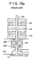
- FIG. 10a shows an example of a configuration of the aforementioned type of the electromagnetic valve.
- a cylinder 140 is formed in a cylinder head 110 of an internal combustion engine, and an upper end of an opening of the cylinder 140 is covered with an electromagnet (valve-opening electromagnet) 139 for energizing a valve element 121 which functions as an intake and exhaust valve of the engine.
- a valve-closing air spring (pneumatic spring) 146 and a valve-opening air spring (pneumatic spring) 148 are formed in the cylinder 140.
- valve-closing air spring 146 is disposed against the bottom face of the cylinder 140, and is provided with a piston 141 connected to a valve shaft 122 of the valve element 121. Furthermore, the structure is such that the compressed air within a pressure chamber 145 defined by the piston 141, cylinder 140, and the bottom face thereof applies to the piston 141 an energizing force in a direction for closing the valve element 121.
- valve-opening air spring 148 is disposed against the opening face of the cylinder 140, that is, the bottom face of the valve-opening electromagnet 139, and is provided with a piston 142 connected to a supporting shaft (armature shaft 123) of an armature 124 on which the electromagnetic force of the valve-opening electromagnet 139 acts. Furthermore, the structure is such that the compressed air within a pressure chamber 147 defined by the piston 141, cylinder 140, and the bottom face of the valve-opening electromagnet 139 which covers the opening face of the cylinder 140 applies to the piston 142 the energizing force in a direction for opening the valve element 121.
- armature shaft 123 connected to the piston 142 of the valve-opening air spring 148 and the valve shaft 122 connected to the piston 142 of the valve-closing air spring 146 are connected to their corresponding pistons 141 and 141 in such a manner as to pass through and protrude from the pistons, such that the armature shaft 123 and the valve shaft 122 oppose with each other.
- a tappet for transmitting power is constituted by the armature shaft 123 and the valve shaft 122 which protrude and oppose with each other.
- an electromagnet (valve-closing electromagnet) 135 for energizing the valve element 121 in the valve closing direction is disposed with the armature 124 provided between the electromagnet 139 and the electromagnet 135.
- the valve element 121 is operated to open and close against a valve seat 111 provided in the cylinder head 110.
- the contact noise generated when the armature 124 contacts the valve-closing electromagnet 135 and the valve-opening electromagnet 139 can certainly be reduced.
- the following inconvenience also occurs when the armature 124 is attracted to the valve-opening electromagnet 135.
- the tappet between the valve shaft 122 and the armature shaft 123 is normally provided with a predetermined clearance, after the valve element 121 is seated on the valve seat 111, the armature shaft 123 separates from the valve shaft 122 and the armature 124 continues to be further attracted by the valve-closing electromagnet 135. Meanwhile, after the valve element 121 is seated on the valve seat 111, the energizing force of the valve-closing air spring 146 toward the valve-closing side is not applied to the armature 124, in correlation with the separation of the armature shaft 123. Therefore, in order to certainly attract (attach) the armature 124 to the valve-closing electromagnet 135, in a manner shown in FIG.
- the amount of power supplied to the valve-closing electromagnet 135 must be increased.
- the electromagnetic force by which the valve-closing electromagnet 135 attracts the armature 124 suddenly increases as a gap between the valve-closing electromagnet 135 and the armature 124 becomes small.
- a speed at which the armature 124 contact the valve-closing electromagnet 135 increases, thereby also increasing the contact noise involved with such contact operation.
- the invention has been made in view of the aforementioned conditions, and it is an object of the invention to provide a control apparatus of an electromagnetic valve by which an armature connected to an armature shaft which transmits power in relation to the valve shaft can be certainly attracted to an electromagnet which attracts the armature in the valve-closing direction of a valve element, while suppressing an increase in power consumption and the like.
- a control apparatus is characterized in that the energizing force of the spring means which energizes the valve element toward the valve-closing side is increased immediately before the valve element is seated,.
- the energizing force of the spring means for energizing the valve element toward the valve-closing side is increased immediately before seating of the valve element. Therefore, compared to a case where the energizing force is not increased, the energizing force for energizing the armature toward the valve-opening side by a resultant force of a pair of spring means is reduced. In addition, if the amount of increase in the energizing force is large, displacement of the armature toward the valve-closing side is accelerated.
- the degree of decrease in the inertia force of the armature due to the energizing force for energizing the armature toward the valve-opening side by the resultant force of the pair of spring means is reduced immediately before the valve element is seated. Furthermore, if the amount of increase in the energizing force of the spring means for energizing the valve element toward the valve-closing side is large, the inertia force of the armature increases. Consequently, the armature can certainly be attracted to the electromagnet which energizes (attracts) the armature in the valve-closing direction of the valve element while suppressing an increase in power consumption and the like.
- a control apparatus is characterized in that the energizing force of the spring means which energizes the valve element toward the valve-opening side is reduced immediately before the valve element is seated.
- the energizing force of the spring means for energizing the valve element toward the valve-opening side is reduced immediately before seating of the valve element. Therefore, compared to a case where the energizing force is not reduced, the energizing force for energizing the armature toward the valve-opening side by a resultant force of a pair of spring means is reduced. In addition, if the amount of decrease in the energizing force of the spring means for energizing the valve element toward the valve-opening side is large, displacement of the armature toward the valve-closing side is accelerated.
- the degree of decrease in the inertia force of the armature due to the energizing force for energizing the armature toward the valve-opening side by the resultant force of the pair of spring means is reduced immediately before the valve element is seated. Furthermore, if the amount of decrease in the energizing force of the spring means for energizing the valve element toward the valve-opening side is large, the inertia force of the armature increases. Consequently, the armature can certainly be attracted to the electromagnet which energizes (attracts) the armature in the valve-closing direction of the valve element while suppressing an increase in power consumption and the like.
- a control apparatus is characterized in that the degree of increase in the energizing force by which the valve-opening air spring and the valve-closing air spring energize the valve element toward the valve-opening side in accordance with displacement of the valve element toward the valve-closing side is forcibly reduced, immediately before the valve element is seated,.
- the inertia force of the armature is reduced by the energizing force which energizes the armature toward the valve-opening side by the resultant force of the valve-opening air spring and the valve-closing air spring.
- the degree of increase in the energizing force by which the valve-opening air spring and the valve-closing air spring energize the valve element toward the valve-opening side in accordance with displacement of the valve element toward the valve-closing side is forcibly reduced immediately before seating of the valve element. Accordingly, the degree of decrease in the inertia force of the armature due to the energizing force for energizing the armature toward the valve-opening side by the resultant force of the valve-opening air spring and the valve-closing air spring is reduced immediately before seating of the valve element. Consequently, the armature can certainly be attracted to the electromagnet which energizes (attracts) the armature in the valve-closing direction of the valve element while suppressing an increase in power consumption and the like.
- At least one of the pair of the spring means is configured as a valve-closing air spring, wherein the valve-closing air spring energizes a piston connected to a valve shaft of the valve element toward the valve-closing side by a pressure within a pressure chamber of the valve-closing air spring, and the control apparatus controls the pressure within the pressure chamber for adjusting an energizing force of the valve-closing air spring.
- the pressure within the pressure chamber of the valve-closing air spring may also preferably be increased immediately before the valve element is seated.
- the pressure within the pressure chamber of the valve-closing air spring is increased immediately before the valve element is seated. Therefore, compared to a case where the pressure within the pressure chamber is not increased, the energizing force for energizing the armature toward the valve-opening side by the resultant force of the pair of spring means is reduced. Furthermore, if the amount of pressure increase is large, displacement of the armature toward the valve-closing side is also accelerated. Accordingly, the degree of decrease in the inertia force of the armature due to the energizing force which energizes the armature toward the valve-opening side by the resultant force of the pair of spring means is reduced immediately before seating of the valve element.
- the armature can certainly be attracted to the electromagnet which energizes (attracts) the armature toward the valve-closing direction of the valve element while suppressing an increase in power consumption and the like.
- the degree of decrease in the pressure within the pressure chamber of the valve-closing air spring involved with displacement toward the valve-closing side is forcibly reduced immediately before the valve element is seated.
- the degree of decrease in the pressure within the pressure chamber of the valve-closing air spring involved with displacement of the valve element toward the valve-closing side is forcibly reduced immediately before the valve element is seated. That is, the degree of decrease in the pressure within the pressure chamber involved with a change in the capacity of the pressure chamber of the valve-closing air spring and the like is forcibly reduced. Therefore, compared to a case where the degree of pressure decrease is not forcibly reduced as mentioned above, the energizing force for energizing the armature toward the valve-opening side by the resultant force of the pair of spring means is reduced.
- the degree of decrease in the inertia force of the armature due to the energizing force which energizes the armature toward the valve-opening side by the resultant force of the pair of spring means is reduced immediately before the valve element is seated. Consequently, the armature can certainly be attracted to the electromagnet which energizes (attracts) the armature toward the valve-closing direction of the valve element while suppressing an increase in power consumption and the like.
- reducing the degree of decrease in the pressure within the pressure chamber also includes not reducing the pressure within the pressure chamber at all.
- At least one of the pair of the spring means is configured as a valve-opening air spring, wherein the valve-opening air spring energizes a piston connected to a valve shaft of the valve element toward the valve-opening side by a pressure within a pressure chamber of the valve-opening air spring, and the control apparatus controls the pressure within the pressure chamber for adjusting an energizing force of the valve-opening air spring.
- the pressure within the pressure chamber of the valve-opening air spring may also preferably be reduced immediately before the valve element is seated.
- the pressure within the pressure chamber of the valve-opening air spring is reduced immediately before the valve element is seated. Therefore, compared to a case where the pressure within the pressure chamber is not reduced, the energizing force for energizing the armature toward the valve-opening side by the resultant force of the pair of spring means is reduced. Furthermore, if the amount of pressure decrease is large, displacement of the armature toward the valve-closing side is also accelerated. Accordingly, the degree of decrease in the inertia force of the armature due to the energizing force which energizes the armature toward the valve-opening side by the resultant force of the pair of spring means is reduced immediately before seating of the valve element.
- the armature can certainly be attracted to the electromagnet which energizes (attracts) the armature toward the valve-closing direction of the valve element while suppressing an increase in power consumption and the like.
- the degree of increase in the pressure within the pressure chamber of the valve-opening air spring involved with displacement toward the valve-closing side is forcibly reduced immediately before the valve element is seated.
- the degree of increase in the pressure within the pressure chamber of the valve-opening air spring involved with displacement of the valve element toward the valve-closing side is forcibly reduced immediately before the valve element is seated. That is, the degree of increase in the pressure within the pressure chamber involved with a change in the capacity of the pressure chamber of the valve-opening air spring and the like is forcibly reduced. Therefore, compared to a case where the degree of pressure increase is not forcibly reduced as mentioned above, the energizing force for energizing the armature toward the valve-opening side by the resultant force of the pair of spring means is reduced.
- the degree of decrease in the inertia force of the armature due to the energizing force which energizes the armature toward the valve-opening side by the resultant force of the pair of spring means is reduced immediately before the valve element is seated. Consequently, the armature can certainly be attracted to the electromagnet which energizes (attracts) the armature toward the valve-closing direction of the valve element while suppressing an increase in power consumption and the like.
- one of the pair of the spring means of the electromagnetic valve is configured as a valve-closing air spring, wherein the valve-closing air spring energizes a piston connected to a valve shaft of the valve element toward the valve-closing side by a pressure within a pressure chamber of the valve-closing air spring, whereas another of the pair of the spring means of the electromagnetic valve is configured as a valve-opening air spring, wherein the valve-opening air spring energizes the piston connected to the valve shaft of the valve element toward the valve-opening side by a pressure within a pressure chamber of the valve-opening air spring.
- the control apparatus controls the pressure within the pressure chamber for adjusting the energizing force of the valve-closing air spring and the valve-opening air spring.
- the degree of increase in the energizing force by which the valve-opening air spring and the valve-closing air spring energize the valve element toward the valve-opening side in accordance with displacement of the valve element toward the valve-closing side is forcibly reduced immediately before the valve element is seated.
- the inertia force of the armature is reduced by the energizing force which energizes the armature toward the valve-opening side by the resultant force of the valve-opening air spring and the valve-closing air spring.
- the degree of increase in the energizing force by which the valve-opening air spring and the valve-closing air spring energize the valve element toward the valve-opening side in accordance with displacement of the valve element toward the valve-closing side is forcibly reduced immediately before seating of the valve element. Accordingly, the degree of decrease in the inertia force of the armature due to the energizing force which energizes the armature toward the valve-opening side by the resultant force of the valve-opening air spring and the valve-closing air spring is reduced immediately before the valve element is seated. Consequently, the armature can certainly be attracted to the electromagnet which energizes (attracts) the armature in the valve-closing direction of the valve element while suppressing an increase in power consumption and the like.
- Each of an intake valve and exhaust valve of an internal combustion engine is configured as an electromagnetic valve which is opened and closed by cooperative operation of an electromagnetic force of an electromagnet and an elastic force (energizing force) of a pair of air springs. More specifically, the electromagnetic valve is equipped with a pair of electromagnets for energizing an armature connected to an armature shaft in both armature axial directions.
- the electromagnetic valve includes a valve-opening air spring for energizing a piston connected to the armature shaft toward the valve-opening side of a valve element by a pressure in a pressure chamber, and a valve-closing air spring for energizing a piston connected to a valve shaft which is an axis of the valve element toward the valve-closing side of the valve element by a pressure in a pressure chamber.
- the valve element is operated to open and close by cooperative operation of the electromagnetic force which acts on the armature by the pair of electromagnets and the energizing force of the pair of air springs. Since the intake valve and the exhaust valve have the same basic structure, the intake valve is taken as an example herein to describe its internal structure.
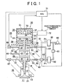
- a cylinder head 10 of an internal combustion engine shown in FIG. 1 is formed with an intake port 12 which is connected to a combustion chamber 11, and is provided with an electromagnetic valve 20 for opening and closing the intake port 12.
- the electromagnetic valve 20 generally comprises a valve element 21 provided at one end of a valve shaft 22, an electromagnetic drive portion 30 which generates an electromagnetic force for opening and closing the valve element 21, and a pair of air springs 46 and 48 which energize the valve element 21 toward a valve-closing side displacement end and a valve-opening side displacement end, respectively.
- the valve element 21 is arranged in an opening of the intake port 12 in such a manner as to be exposed to the inside of the combustion chamber 11.
- a valve seat 13 is provided at the outer edge of the opening of the intake port 12.
- the intake port 12 is opened and closed as the valve element 21 is separated from or seated on the valve seat 13. That is, as the valve element 21 is displaced upward in FIG. 1 to be seated on the valve seat 13, the intake port 12 is closed with respect to the combustion chamber 11. Furthermore, as the valve element 21 seated on the valve seat 13 is displaced downward in FIG. 1 to be separated from the valve seat 13, the intake port 12 is opened with respect to the combustion chamber 11.
- valve shaft 22 whose one end is provided with the valve element 21 is supported by a valve guide 14 fixed to the cylinder head 10 in such a manner as to allow reciprocating motion in an axial direction.
- the upper end of the valve shaft 22 is placed in contact with the lower end of an armature shaft 23.
- the armature shaft 23 is supported by an armature guide 15 fixed to the cylinder head 10 in such a manner as to allow reciprocating motion coaxially with the valve shaft 22.
- an armature 24 that is made of high permeable material and generally formed in a disc shape is fixed. Furthermore, the upper portion of the armature shaft 23 on which the armature 24 is fixed is housed within a casing 31 of the electromagnetic drive portion 30.
- an upper core 32 made of high permeable material is fixed above the armature 24.
- An annular groove 33 is formed on a face of the upper core 32 that faces the armature 24, and a cylindrically-wound electromagnetic coil 34 is housed within the groove 33.
- the upper core 32 and the electromagnetic coil 34 constitute a valve-closing electromagnet 35 for operating the valve element 21 in a valve-closing direction.
- a lower core 36 also made of high permeable material is fixed at a predetermined distance from the upper core 32. Also on the lower core 36, an annular groove 37 is formed on a face that faces the armature 24, and a cylindrically-wound electromagnetic coil 38 is housed within the groove 37.
- the lower core 36 and the electromagnetic coil 38 constitute a valve-opening electromagnet 39 for operating the valve element 21 in a valve-opening direction.
- a displacement sensor 70 is provided for detecting displacement of the armature 24. A lift position of the valve element 21 can be confirmed based on a detection result of the displacement sensor 70.
- a cylinder 40 with an open circular shape is formed between the valve guide 14 and the armature guide 15. Furthermore, a generally disc shaped piston 42 is fixed to the valve shaft 22, and also a generally disc shaped piston 42 is fixed to the armature shaft 23. These pistons 41 and 42 are disposed in such a manner allowing reciprocating motion in an axial direction of the valve shaft 22 and the armature shaft 23 while being slidably in contact with a side wall of the cylinder 40.
- a middle space 43 formed between the piston 41 and the piston 42 is open to the outside via a communicating passage 44. Furthermore, a valve-closing air spring 46 and a valve-opening air spring 48 are constituted with the space 43 provided therebetween.
- the valve-closing air spring 46 is constituted of the piston 4 land a portion of the cylinder 40 on the valve guide 14 side.
- a space 45 formed between the valve guide 14 and the piston 41 fixed to the valve shaft 22 is supplied with compressed air via an air supply passage 50, and the compressed air within the space 45 is discharged through an exhaust passage 51.
- the space 45, the air supply passage 50, and the exhaust passage 51 constitute a pressure chamber of the valve-closing air spring 46.
- the air pressure within the pressure chamber (more accurately, a pressure difference between the air pressure within the pressure chamber and that within the space 43, or the atmospheric pressure) energizes the valve shaft 22 toward the valve-closing side (upward in FIG. 1) of the valve element 21 via the piston 41.
- valve-opening air spring 48 is constituted of the piston 42 and a portion of the cylinder 40 on the armature guide 15 side.
- a space 47 formed between the armature guide 15 and the piston 42 fixed to the armature shaft 23 is supplied with compressed air via an air supply passage 52, and the compressed air within the space 47 is discharged through an exhaust passage 53.
- the space 47, the air supply passage 52, and the exhaust passage 53 constitute a pressure chamber of the valve-opening air spring 48.
- the air pressure within the pressure chamber (more accurately, a pressure difference between the air pressure within the pressure chamber and that within the space 43, or the atmospheric pressure) energizes the armature shaft 23 toward the valve-opening side (downward in FIG. 1) of the valve element 21 via the piston 42.
- the air pressure circuit is provided with an air pump 60 and a reservoir tank 62.
- the air pump 60 compresses air taken in from outside and supplies the compressed air to the reservoir tank 62 via a throttle 61.
- the compressed air supplied from the air pump 60 is accumulated in the reservoir tank 62.
- a pressure of the compressed air accumulated in the reservoir tank 62 is maintained constant by a regulator or the like (not shown).
- the reservoir tank 62 is connected to the pressure chamber of the valve-closing air spring 46 via a supply passage 63. Furthermore, the reservoir tank 62 is connected to the pressure chamber of the valve-opening air spring 48 via a supply passage 64.
- the supply passage 63 is connected to the air supply passage 50 via a non-return valve 65. Furthermore, the supply passage 64 is connected to the air supply passage 52 via a non-return valve 66.
- the non-return valves 65 and 66 are differential pressure operating valves of normally closed type, and open when the pressures within the pressure chambers of the valve-closing air spring 46 and the valve-opening air spring 48 become lower than the pressures of the supply passages 63 and 64, so as to supply compressed air to the pressure chambers.
- the exhaust passage 51 of the valve-closing air spring 46 and the exhaust passage 53 of the valve-opening air spring 48 are provided with a relief valves 67 and 68, respectively.
- the relief valves 67 and 68 normally function as pressure operating valves of normally closed type which open when the air pressure of the exhaust passages 51 and 53 has become equal to or higher than a predetermined level, so as to discharge extra compressed air from the pressure chamber.
- the relief valves 67 and 68 are also structured so as to be forcibly opened or closed by a command from outside. The downstream of the relief valves 67 and 68 is open to the air.
- the amount of compressed air filled within the pressure chambers of the valve-closing air spring 46 and the valve-opening air spring 48 is regulated through the non-return valves 65 and 66, the relief valves 67 and 68, and the like, so as to obtain a desired elastic force.
- each of intake valve and exhaust valve of the internal combustion chamber is provided with the non-return valves 65 and 66, the relief valves 67 and 68, and the supply passages 63 and 64. According to this structure, the air pressure of the air spring provided for each intake valve and exhaust valve of the internal combustion engine can also be adjusted individually.
- an electronic control unit (ECU) 71 which executes various controls of the internal combustion engine, detection signals of various sensors, such as a crank angle sensor and an accelerator sensor, that detect an operation state of the engine, in addition to a detection signal of the displacement sensor 70 are input. Furthermore, an electromagnetic coil driving circuit 72 is connected to an output port of the electronic control unit 71.
- the electronic control unit 71 generates a control signal for supplying power to both electromagnetic coils 34 and 38 on the basis of the engine operation state identified based on the detection signals of each sensor mentioned above, and outputs the control signal to the electromagnetic coil driving circuit 72.
- the electromagnetic coil driving circuit 72 amplifies the control signal to generate an electromagnetic coil driving current, and supplies power to each of the electromagnetic coils 34 and 38.
- the electronic control unit 71 controls the relief valves 67 and 68 so as to adjust the air pressure within the pressure chambers of the valve-closing air spring 46 and the valve-opening air spring 48 according to the engine operation state.
- valve element 21 which is displaced along with the valve shaft 22 and the armature shaft 23 is capable of reciprocating between a position at which the valve element 21 seats on the valve seat 13 and a position at which the armature 24 contacts the lower core 36.
- the valve element 21 is kept apart from the valve seat 13 to the maximum, and thus the electromagnetic valve 20 is fully opened.
- the lift position of the valve element 21 in this state is called a "full-open position.”
- the valve element 21 which is displaced along with the valve shaft 22 and the armature shaft 23 is placed at a position at which an elastic force Fcl of the valve-closing air spring 46 and an elastic force Fop of the valve-opening air spring 48 are equal.
- a lift position of the valve element 21 at which the elastic force Fcl of the valve-closing air spring 46 and the elastic force Fop of the valve-opening air spring 48 are balanced is called a "neutral position.”
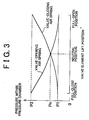
- FIG. 3 illustrates a pattern of such air pressure change within the pressure chamber based on the lift position of the valve element 21.
- the capacity of the pressure chamber of the valve-closing air spring 46 is increased as the lift position of the valve element 21 moves toward the full-close position. Therefore, as shown in FIG. 3, the air pressure within the pressure chamber increases from a minimum pressure P1 at the full-close position as the lift position moves toward the valve-opening side, and becomes a maximum pressure P2 at the full-open position.
- the capacity of the pressure chamber of the valve-opening air spring 48 is, after being maximized at the full-open position, reduced as the lift position of the valve element 21 moves toward the full-close position. Therefore, the air pressure within the pressure chamber of the valve-opening air spring 48 is increased from a minimum pressure P1 at the full-open position as the lift position moves toward the valve-closing side, and becomes a maximum pressure P2 at the full-close position.
- the air pressure within each pressure chamber when the capacity thereof is at its maximum is sufficiently higher than an atmospheric pressure P0.
- a pressure of the compressed air within the reservoir tank 62 is set to the minimum pressure P1.
- valve element 21 In a state where the valve element 21 is placed at the full-close position, the valve element 21 is, as described above, energized toward the valve-opening side by the resultant force of the elastic forces of the valve-closing air spring 46 and the valve-opening air spring 48.
- the valve element 21 is held at the full-close position by supplying a holding current to the electromagnetic coil 34 of the valve-closing electromagnet 35 to generate an electromagnetic force which attracts and holds the armature 24 to the upper core 32.
- the magnitude of holding current supplied to the electromagnetic coil 34 is set so as to maintain the state in which the armature 24 is attracted to the upper core 32 against the resultant force of the elastic forces of the valve-closing air spring 46 and the valve-opening air spring 48.
- the resultant force of the elastic forces of the valve-closing air spring 46 and the valve-opening air spring 48 decreases.
- the resultant force of the elastic forces starts to act in a direction to pull the valve element 21 back.
- the valve element 21 continues to move further toward the valve-opening side, to some extent by its own inertia force, against the resultant force of the elastic forces.
- valve element 21 when the valve element 21 reaches a predetermined position, an attracting current is supplied to the electromagnetic coil 38 of the valve-opening electromagnet 39.
- An electromagnetic force generated in the valve-opening electromagnet 39 due to the supply of the attracting current attracts the armature 24 toward the lower core 36.
- the valve element 21 continues to move, by its own inertia force and the electromagnetic force of the electromagnet 39, toward the valve-opening side against the resultant force of the elastic forces the valve-closing air spring 46 and the valve-opening air spring 48.
- the magnitude of the attracting current is set, for example, according to the lift position of the valve element 21 or the like that is detected by the displacement sensor 70, so that the armature 24 is certainly attracted to the lower core 36.
- valve-closing electromagnet 35 and the valve-opening electromagnet 39 are controlled. That is, by stopping the supply of holding current to the electromagnetic coil 38 of the valve-opening electromagnet 39, the valve element 21 starts to move toward the valve-closing side, and by supplying the attracting current to the electromagnetic coil 34 of the valve-closing electromagnet 35, the armature 24 is attracted to the upper core 32.
- opening and closing operation of the electromagnetic valve 20 is continued by sequentially repeating the aforementioned current supply control.
- the above are the descriptions of the operation mode of the electromagnetic valve 20 during normal valve opening and closing operation.
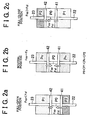
- the armature 24 is attracted to the valve-closing electromagnet 35 and is displaced toward the valve-closing electromagnet 35 side. Such displacement continues until the armature 24 contacts the valve-closing electromagnet 35.
- the armature shaft 23 separates form the valve shaft 22 after the valve element 21 is seated on the valve seat 13, the armature 24 is not applied with the energizing force by the valve-closing air spring 46.
- a pressure within the pressure chamber of the valve-closing air spring 46 is increased immediately before the valve element 21 is seated.
- the pressure within the pressure chamber of the valve-closing air spring 46 is increased during a predetermined period immediately before the armature shaft 23 starts separate from the valve shaft 22 to move toward the valve-closing electromagnet 35 side upon seating of the valve element 21 on the valve seat 13.
- the energizing force for energizing the armature 24 toward the valve-opening side by the resultant force of the elastic forces the valve-closing air spring 46 and the valve-opening air spring 48 is reduced.
- an increase, involved with displacement of the valve element 21 toward the valve-closing side, in the energizing force toward the valve-opening side that is applied to the valve element 21 by the valve-opening air spring 48 and the valve-closing air spring 46 in accordance with such displacement is at least suppressed immediately before the valve element 21 is seated.
- the degree of decrease in the inertia force of the armature 24 due to the energizing force for energizing the armature 24 toward the valve-opening side by the resultant force of the valve-closing air spring 46 and the valve-opening air spring 48 is at least reduced immediately before the valve element 21 is seated. Consequently, the armature 24 can appropriately be attracted to be brought into contact with the valve-closing electromagnet 35 without increasing the energizing force of the valve-closing electromagnet 35 for energizing the armature 24 toward the valve-closing side.
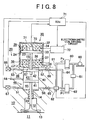
- a high-pressure reservoir tank 80 which accumulates compressed air with a pressure (Px) higher than a pressure (P1) of compressed air accumulated in the reservoir tank 62 is provided.
- the high-pressure reservoir tank 80 also accumulates the compressed air supplied from the air pump 60.
- a pressure of the compressed air accumulated in the high-pressure reservoir tank 80 is also maintained constant by a regulator or the like (not shown).
- the throttle 61 is not provided between the air pump 60 and the high-pressure reservoir tank 80, thereby making it easier to accumulate, in the high-pressure reservoir tank 80, the compressed air with a pressure higher than the pressure of the compressed air accumulated in the reservoir tank 62.
- the high-pressure reservoir tank 80 is connected to the pressure chamber of the valve-closing air spring 46 through a supply passage 81. Furthermore, a switching valve 82 is provided in the supply valve 63 in order to selectively supply the pressure chamber of the valve-closing air spring 46 with the compressed air in the high-pressure reservoir tank 80 and that in the reservoir tank 62. The switching valve 82 switches, based on a command from the electronic control unit 71, between communication between the upstream and downstream of the supply passage 63 and that between the supply passage 81 and the downstream of the supply passage 63.
- the switching valve 82 switches between communication between the reservoir tank 62 and the pressure chamber of the valve-closing air spring 46 via the non-return valve 65, and that between the high-pressure reservoir tank 80 and the pressure chamber of the valve-closing air spring 46 via the non-return valve 65.
- the switching valve 82 is switched so as to increase the pressure within the pressure chamber of the valve-closing air spring 46 immediately before the valve element 21 is seated on the valve seat 13. That is, as shown in FIG. 6, the switching valve 82 is switched so as to supply the compressed air accumulated in the high-pressure reservoir tank 80 to the pressure chamber of the valve-closing air spring 46. Accordingly, the non-return valve 65 is closed and the compressed air accumulated in the high-pressure reservoir tank 80 flows into the pressure chamber of the valve-closing air spring 46. As a result, the pressure within the pressure chamber of the valve-closing air spring 46 immediately before the valve element 21 is seated on the valve seat 13 can be increased compared to that theretofore. In this case, when the compressed air accumulated in the high-pressure reservoir tank 80 is supplied to the pressure chamber of the valve-closing air spring 46, a control such as forcibly closing the relief valve 67 is executed.
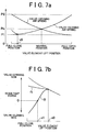
- the pressure within the pressure chamber of the valve-closing air spring 46 is forcibly increased during displacement of the valve element 21 toward the valve-closing side from a predetermined displacement x0 in the vicinity of the full-close position.
- the valve element 21 is energized toward the valve-opening side by the resultant force of the elastic forces of the valve-opening air spring 48 and the valve-closing air spring 46. This energizing force increases in accordance with displacement of the valve element 21 toward the valve-closing side as shown in FIG. 7b.
- the armature 24 By forcibly increasing the pressure within the pressure chamber of the valve-closing air spring 46, the armature 24 can be brought into contact with the valve-closing electromagnet 35 as shown in FIG. 8.
- a pressure within the pressure chamber of the valve-closing air spring 46 is forcibly increased immediately before the valve element 21 is seated. Consequently, the degree of decrease in the inertia force of the armature 24 due to the energizing force for energizing the armature 24 toward the valve-opening side by the resultant force of the valve-closing air spring 46 and the valve-opening air spring 48 can be sufficiently reduced immediately before the valve element 21 is seated. Furthermore, if the amount of increase in the pressure within the pressure chamber of the valve-closing air spring 46 immediately before seating of the valve element is large, the inertia force of the armature can also be increased. In other words, displacement of the armature 24 toward the valve-closing electromagnet 35 side is also accelerated. As a result, the armature 24 can certainly be attracted to and brought into contact with the valve-closing electromagnet 35.
- the reservoir tank 62 and the high-pressure reservoir tank 80 which accumulates compressed air with a pressure higher than that of the reservoir tank 62 are provided. Accordingly, the pressure within the pressure chamber of the valve-closing air spring 46 can forcibly increased immediately before seating of the valve element 21 in a suitable manner.
- the pressure within the pressure chamber of the valve-closing air spring 46 is forcibly increased immediately before the valve element 21 is seated on the valve seat 13.
- the pressure within the pressure chamber of the valve-opening air spring 48 is reduced immediately before the valve element 21 is seated. Therefore, compared to a case in which the pressure is not forcibly reduced as descried above, the energizing force for energizing the armature 24 toward the valve-opening side by the resultant force of the valve-closing air spring 46 and the valve-opening air spring 48 is reduced.
- the degree of decrease in the inertia force of the armature 24 due to the energizing force for energizing the armature 24 toward the valve-opening side by the resultant force of a pair of spring means is reduced immediately before the valve element 21 is seated. Furthermore, if the amount of the aforementioned pressure reduction is large, the inertia force in accordance with the displacement of the armature 24 toward the valve-closing side is increased. Accordingly, the armature 24 can certainly be attracted to and brought into contact with the valve-closing electromagnet 35 without increasing the energizing force of the valve-closing electromagnet 35 that energizes the armature 24 toward the valve-opening side.
- the relief valve 68 is opened by a predetermined degree so as to reduce the pressure within the pressure chamber of the valve-opening air spring 48 immediately before the valve element 21 is seated. Consequently, the armature 24 can be brought into contact with the valve-closing electromagnet 35 just like in the case of the first exemplary embodiment.
- a pressure within the pressure chamber of the valve-opening air spring 48 is forcibly reduced immediately before the valve element 21 is seated. Accordingly, the degree of decrease in the inertia force of the armature 24 due to the energizing force for energizing the armature 24 toward the valve-opening side by the resultant force of the valve-closing air spring 46 and the valve-opening air spring 48 can be sufficiently reduced immediately before the valve element 21 is seated. Furthermore, if the amount of decrease in the pressure within the pressure chamber of the valve-opening air spring 48 immediately before seating of the valve element is large, the inertia force of the armature 24 can also be increased. In other words, displacement of the armature 24 toward the valve-closing electromagnet 35 side is also accelerated. As a result, the armature 24 can certainly be attracted to and brought into contact with the valve-closing electromagnet 35.
- the invention is not limited to the control by which the pressure within the pressure chamber of the valve-closing air spring 46 is forcibly increased immediately before the valve element 21 is seated, as described in the first exemplary embodiment. Any control will do as long as the degree of decrease in the pressure within the pressure chamber of the valve-closing air spring 46 involved with displacement of the valve element 21 toward the valve-closing side is forcibly reduced immediately before the valve element 21 is seated. That is, for example, the pressure may assume a larger value than the pressure within the pressure chamber of the valve-opening air spring represented by a curve in FIG. 3, so as to reduce the degree of decrease in the pressure within the pressure chamber involved with displacement of the valve element toward the valve-closing side.
- control means for forcibly reducing, immediately before the valve element 21 is seated on the valve seat 13, the degree of decrease in the pressure within the pressure chamber of the valve-closing air spring 46 involved with displacement of the valve element 21 toward the valve-opening side may be configured to include the high-pressure reservoir tank 80, the relief valve 67, and the electronic control unit 71. Furthermore, this control means may be provided with, in place of the non-return valve 65, for example, a pressure controller or the like which regulates a pressure of compressed air supplied to the pressure chamber of the valve-closing air spring 46. In this case, by increasing by the pressure controller the pressure of the compressed air supplied to the pressure chamber, the degree of decrease in the pressure within the pressure chamber immediately before seating of the valve element is reduced.
- the invention is not limited to the control by which the pressure within the pressure chamber of the valve-opening air spring 48 is forcibly reduced immediately before the valve element 21 is seated, as described in the second exemplary embodiment. Any control will do as long as the degree of increase in the pressure within the pressure chamber of the valve-opening air spring 48 involved with displacement of the valve element 21 toward the valve-closing side is forcibly reduced immediately before the valve element 21 is seated. That is, for example, the pressure may assume a smaller value than the pressure within the pressure chamber of the valve-opening air spring represented by a curve in FIG. 3, so as to reduce the degree of increase in the pressure within the pressure chamber involved with displacement of the valve element toward the valve-closing side.
- control means for forcibly reducing, immediately before the valve element 21 is seated on the valve seat 13, the degree of increase in the pressure within the pressure chamber of the valve-opening air spring 48 involved with displacement of the valve element 21 toward the valve-closing side may be configured to include, for example, the relief valve 68 and the electronic control unit 71.
- the control means for increasing the pressure within the pressure chamber of the valve-closing air spring 46 immediately before the valve element 21 is seated on the valve seat 13 is not limited those configured to include the high-pressure reservoir tank 80, the relief valve 67, and the electronic control unit 71.
- this control means may be provided with, in place of the non-return valve 65, a pressure controller or the like which regulates a pressure of compressed air supplied to the pressure chamber of the valve-closing air spring 46. In this case, by increasing by the pressure controller the pressure of the compressed air supplied to the pressure chamber, the pressure within the pressure chamber is increased immediately before seating of the valve element.
- the control means for reducing, immediately before the valve element 21 is seated on the valve seat 13, the pressure within the pressure chamber of the valve-opening air spring 48 in accordance with displacement of the valve element 21 toward the valve-closing side, is not limited to those configured to include the relief valve 68 and the electronic control unit 71.
- the structure of the air pressure circuit, the arrangement of the air springs 46 and 48 in the electromagnetic valve 20, the structure of the control system, and the like according to the aforementioned exemplary embodiments may be arbitrarily changed.
- an air spring that generates an elastic force by the pressure of the compressed air filled in the pressure chamber is adopted as a spring for energizing the valve element 21 toward the displacement ends on the valve-opening side and valve-closing side.
- any gas other than the atmospheric air may also be used as a source for generating the elastic force.
- spring means other than a pneumatic spring may be adopted as long as the energizing force can be arbitrarily changed.
- a pressure chamber of a valve-opening air spring (48) is supplied with compressed air within a reservoir tank (62) via a non-return valve (65).
- a pressure chamber of a valve-closing air spring (46) is selectively supplied, by a switching valve (82) via the non-return valve (65), with compressed air within the reservoir tank (62) and compressed air within a high-pressure reservoir tank (80) whose pressure is higher than that within the reservoir tank (62).
- the compressed air supplied to the pressure chamber of the valve-closing air spring (46) is switched to the compressed air within the high-pressure reservoir tank (80).
Landscapes
- Engineering & Computer Science (AREA)
- Mechanical Engineering (AREA)
- General Engineering & Computer Science (AREA)
- Magnetically Actuated Valves (AREA)
- Valve Device For Special Equipments (AREA)
- Valves And Accessory Devices For Braking Systems (AREA)
- Vehicle Body Suspensions (AREA)
Abstract
Description
Claims (10)
- A control apparatus of an electromagnetic valve which comprises a valve element (21), an armature (24) connected to an armature shaft (23) which is engaged with the valve element, a pair of spring means (46, 48) for energizing the valve element toward a valve-opening side and a valve-closing side, respectively, and an electromagnet (35) for energizing the armature (24) toward the valve-closing side of the valve element (21), and operates the valve element (21) to open and close by cooperative operation of an electromagnetic force of the electromagnet (35) and an energizing force of the spring means (46, 48), characterized in that
the energizing force of the spring means (46) for energizing the valve-element (21) toward the valve-closing side is increased immediately before seating of the valve element (21). - A control apparatus of an electromagnetic valve which comprises a valve element (21), an armature (24) connected to an armature shaft (23) which is engaged with the valve element, a pair of spring means (46, 48) for energizing the valve element toward a valve-opening side and a valve-closing side, respectively, and an electromagnet (35) for energizing the armature (24) toward the valve-closing side of the valve element (21), and operates the valve element (21) to open and close by cooperative operation of an electromagnetic force of the electromagnet (35) and an energizing force of the spring means (46, 48), characterized in that
the energizing force of the spring means (48) for energizing the valve-element (21) toward the valve-opening side is reduced immediately before seating of the valve element (21). - The control apparatus of the electromagnetic valve according to claim 1 or 2, characterized in that
at least one of the pair of the spring means (46, 48) is configured as a valve-closing pneumatic spring (46), wherein the valve-closing pneumatic spring (46) energizes a piston (41) connected to a valve shaft (22) of the valve element toward the valve-closing side by a pressure within a pressure chamber of the valve-closing pneumatic spring (46), and the control apparatus controls the pressure within the pressure chamber (45) for adjusting an energizing force of the valve-closing pneumatic spring (46). - The control apparatus of the electromagnetic valve according to claim 3, characterized in that
the pressure within the pressure chamber (45) of the valve-closing pneumatic spring (46) is increased immediately before seating of the valve element (21). - The control apparatus of the electromagnetic valve according to claim 3, characterized in that
a degree of decrease in the pressure within the pressure chamber (45) of the valve-closing pneumatic spring (46) involved with displacement toward the valve-closing side is forcibly reduced immediately before seating of the valve element (21). - The control apparatus of the electromagnetic valve according to claim 1 or 2, characterized in that
at least one of the pair of the spring means (46, 48) is configured as a valve-opening pneumatic spring (48), wherein the valve-opening pneumatic spring (48) energizes a piston (41) connected to a valve shaft (22) of the valve element toward the valve-opening side by a pressure within a pressure chamber (47) of the valve-opening pneumatic spring (48), and the control apparatus controls the pressure within the pressure chamber (47) for adjusting an energizing force of the valve-opening pneumatic spring (48). - The control apparatus of the electromagnetic valve according to claim 6, characterized in that
the pressure within the pressure chamber (47) of the valve-opening pneumatic spring (48) is reduced immediately before seating of the valve element (21). - The control apparatus of the electromagnetic valve according to claim 6, characterized in that
a degree of increase in the pressure within the pressure chamber (47) of the valve-opening pneumatic spring (48) involved with displacement toward the valve-closing side is forcibly reduced immediately before seating of the valve element (21). - The control apparatus of the electromagnetic valve according to claim 1 or 2, characterized in that
one of the pair of the spring means (46, 48) of the electromagnetic valve is configured as a valve-closing pneumatic spring (46), wherein the valve-closing pneumatic spring (46) energizes a piston (41) connected to a valve shaft (22) of the valve element toward the valve-closing side by a pressure within a pressure chamber (45) of the valve-closing pneumatic spring (46), whereas another of the pair of the spring means (46, 48) of the electromagnetic valve is configured as a valve-opening pneumatic spring (48), wherein the valve-opening pneumatic spring (48) energizes the piston (41) connected to the valve shaft (22) of the valve element toward the valve-opening side by a pressure within a pressure chamber (47) of the valve-opening pneumatic spring (48), and the control apparatus controls the pressure within the pressure chambers (45, 47) for adjusting energizing forces of the valve-closing pneumatic spring (46) and the valve-opening pneumatic spring (48). - The control apparatus of the electromagnetic valve according to claim 9, characterized in that
a degree of increase in the energizing force by which the valve-opening pneumatic spring (48) and the valve-closing pneumatic spring (46) energize the valve element (21) toward the valve-opening side in accordance with displacement of the valve element (21) toward the valve-closing side is forcibly reduced immediately before seating of the valve element.
Applications Claiming Priority (2)
| Application Number | Priority Date | Filing Date | Title |
|---|---|---|---|
| JP2002118806 | 2002-04-22 | ||
| JP2002118806A JP2003314734A (en) | 2002-04-22 | 2002-04-22 | Control device for electromagnetically driven valve |
Publications (2)
| Publication Number | Publication Date |
|---|---|
| EP1357265A2 true EP1357265A2 (en) | 2003-10-29 |
| EP1357265A3 EP1357265A3 (en) | 2004-01-02 |
Family
ID=28786739
Family Applications (1)
| Application Number | Title | Priority Date | Filing Date |
|---|---|---|---|
| EP03009055A Withdrawn EP1357265A3 (en) | 2002-04-22 | 2003-04-17 | Electromagnetic valve control apparatus |
Country Status (4)
| Country | Link |
|---|---|
| US (1) | US20030196615A1 (en) |
| EP (1) | EP1357265A3 (en) |
| JP (1) | JP2003314734A (en) |
| KR (1) | KR20030083546A (en) |
Families Citing this family (7)
| Publication number | Priority date | Publication date | Assignee | Title |
|---|---|---|---|---|
| DE102007058007A1 (en) | 2007-12-03 | 2009-06-04 | Alfa Laval Kolding A/S | Drive arrangement for valve devices |
| WO2010106361A1 (en) * | 2009-03-16 | 2010-09-23 | Artemis Intelligent Power Limited | Electronically controlled valves |
| CN102913299A (en) * | 2012-10-09 | 2013-02-06 | 哈尔滨工程大学 | Air spring electromagnetically-driving valve mechanism of diesel engine |
| CN104235423B (en) * | 2013-06-10 | 2017-02-08 | 陈镇汉 | High-pollution-resistance electro-hydraulic pressure distributing device |
| CN103615571B (en) * | 2013-12-04 | 2016-04-13 | 宜昌星航宇伺服科技有限公司 | A kind of oil rub resistance solenoid valve |
| US20230127691A1 (en) * | 2021-10-21 | 2023-04-27 | Kenneth Schulz | Electronic Valve Train Assembly |
| US12152688B2 (en) | 2022-11-29 | 2024-11-26 | Eto Magnetic Gmbh | Bi-stable solenoid device, moving magnet actuator, valve and method for operating the bi-stable solenoid device |
Family Cites Families (11)
| Publication number | Priority date | Publication date | Assignee | Title |
|---|---|---|---|---|
| US4794890A (en) * | 1987-03-03 | 1989-01-03 | Magnavox Government And Industrial Electronics Company | Electromagnetic valve actuator |
| US5094426A (en) * | 1990-04-27 | 1992-03-10 | John Zajac | Metering valve assembly |
| US5152260A (en) * | 1991-04-04 | 1992-10-06 | North American Philips Corporation | Highly efficient pneumatically powered hydraulically latched actuator |
| JP3106890B2 (en) * | 1995-01-11 | 2000-11-06 | トヨタ自動車株式会社 | Valve drive for internal combustion engine |
| DE19733186A1 (en) * | 1997-07-31 | 1999-02-04 | Fev Motorentech Gmbh & Co Kg | Gas exchange valve apparatus for piston engine |
| JP2000027616A (en) * | 1998-07-10 | 2000-01-25 | Nissan Motor Co Ltd | Valve train for internal combustion engine |
| JP3583951B2 (en) * | 1999-06-07 | 2004-11-04 | 株式会社豊田自動織機 | Capacity control valve |
| DE10003115A1 (en) * | 2000-01-26 | 2001-08-02 | Bayerische Motoren Werke Ag | Valve control for internal combustion engines with an electro-magnetic actuator equipped with gas springs |
| US6474620B2 (en) * | 2000-12-20 | 2002-11-05 | Caterpillar Inc | Method of controlling hydraulically actuated valves and engine using same |
| US6418906B1 (en) * | 2001-04-02 | 2002-07-16 | Caterpillar Inc. | Duration control strategy for a hydraulically actuated engine compression release brake |
| US6701876B2 (en) * | 2001-09-27 | 2004-03-09 | Visteon Global Technologies, Inc. | Electromechanical engine valve actuator system with reduced armature impact |
-
2002
- 2002-04-22 JP JP2002118806A patent/JP2003314734A/en active Pending
- 2002-10-07 KR KR1020020061032A patent/KR20030083546A/en not_active Ceased
-
2003
- 2003-04-14 US US10/412,208 patent/US20030196615A1/en not_active Abandoned
- 2003-04-17 EP EP03009055A patent/EP1357265A3/en not_active Withdrawn
Also Published As
| Publication number | Publication date |
|---|---|
| JP2003314734A (en) | 2003-11-06 |
| US20030196615A1 (en) | 2003-10-23 |
| KR20030083546A (en) | 2003-10-30 |
| EP1357265A3 (en) | 2004-01-02 |
Similar Documents
| Publication | Publication Date | Title |
|---|---|---|
| US8272399B2 (en) | Fluid admission system for providing a pressure-balanced valve | |
| US6871618B2 (en) | Valve actuating device, and method for controlling same | |
| JP2013508607A (en) | Fluid-biased hydraulic control valve with armature piston | |
| JPH11280660A (en) | Capacity control valve for variable capacity compressor | |
| US20090032750A1 (en) | Control valve for variable capacity compressors | |
| EP1357265A2 (en) | Electromagnetic valve control apparatus | |
| EP1106791A2 (en) | Control system for electromagnetic actuator | |
| JP2589424B2 (en) | Pressure control valve | |
| US7437881B2 (en) | Control valve for variable displacement compressor | |
| JPH11107929A (en) | Capacity control valve for variable displacement compressor | |
| JP2004270687A (en) | Fluid force actuator that operates an engine cylinder valve | |
| US6817324B2 (en) | Control unit of electromagnetically driven valve and control method thereof | |
| US6997433B2 (en) | Electronic valve actuator having vibration cancellation | |
| JP5187149B2 (en) | Valve drive apparatus for internal combustion engine | |
| EP1371820B1 (en) | Control apparatus for electromagnetically driven valve | |
| JP3749313B2 (en) | Negative pressure control valve | |
| JPH0893425A (en) | Variable valve device for internal combustion engine | |
| JP2002535530A (en) | Device for driving a gas exchange valve | |
| JP3424306B2 (en) | Variable valve train for internal combustion engine | |
| JP3746668B2 (en) | Electronically controlled fuel injection device | |
| JP4120229B2 (en) | Solenoid valve | |
| JP2002266728A (en) | Fuel control valve and high pressure fuel pump | |
| JP2003314733A (en) | Control device for electromagnetically driven valve | |
| JP3027351B2 (en) | Pressure control valve and pressure control method thereof | |
| JPH07180516A (en) | Variable valve device for internal combustion engine |
Legal Events
| Date | Code | Title | Description |
|---|---|---|---|
| PUAI | Public reference made under article 153(3) epc to a published international application that has entered the european phase |
Free format text: ORIGINAL CODE: 0009012 |
|
| 17P | Request for examination filed |
Effective date: 20030417 |
|
| AK | Designated contracting states |
Kind code of ref document: A2 Designated state(s): AT BE BG CH CY CZ DE DK EE ES FI FR GB GR HU IE IT LI LU MC NL PT RO SE SI SK TR |
|
| AX | Request for extension of the european patent |
Extension state: AL LT LV MK |
|
| PUAL | Search report despatched |
Free format text: ORIGINAL CODE: 0009013 |
|
| AK | Designated contracting states |
Kind code of ref document: A3 Designated state(s): AT BE BG CH CY CZ DE DK EE ES FI FR GB GR HU IE IT LI LU MC NL PT RO SE SI SK TR |
|
| AX | Request for extension of the european patent |
Extension state: AL LT LV MK |
|
| 17Q | First examination report despatched |
Effective date: 20040809 |
|
| AKX | Designation fees paid |
Designated state(s): DE FR GB IT |
|
| STAA | Information on the status of an ep patent application or granted ep patent |
Free format text: STATUS: THE APPLICATION IS DEEMED TO BE WITHDRAWN |
|
| 18D | Application deemed to be withdrawn |
Effective date: 20051101 |