EP1357071A2 - Sheet material positioning device - Google Patents
Sheet material positioning device Download PDFInfo
- Publication number
- EP1357071A2 EP1357071A2 EP03006800A EP03006800A EP1357071A2 EP 1357071 A2 EP1357071 A2 EP 1357071A2 EP 03006800 A EP03006800 A EP 03006800A EP 03006800 A EP03006800 A EP 03006800A EP 1357071 A2 EP1357071 A2 EP 1357071A2
- Authority
- EP
- European Patent Office
- Prior art keywords
- swinging
- sheet material
- printing plate
- plate
- rotating drum
- Prior art date
- Legal status (The legal status is an assumption and is not a legal conclusion. Google has not performed a legal analysis and makes no representation as to the accuracy of the status listed.)
- Withdrawn
Links
- 239000000463 material Substances 0.000 title claims abstract description 48
- 238000000034 method Methods 0.000 claims description 6
- 230000002093 peripheral effect Effects 0.000 description 28
- 239000007787 solid Substances 0.000 description 13
- 238000007599 discharging Methods 0.000 description 12
- 238000004080 punching Methods 0.000 description 10
- 238000013459 approach Methods 0.000 description 7
- 238000001454 recorded image Methods 0.000 description 2
- 229920002379 silicone rubber Polymers 0.000 description 1
- 238000004804 winding Methods 0.000 description 1
Images


Classifications
-
- B—PERFORMING OPERATIONS; TRANSPORTING
- B65—CONVEYING; PACKING; STORING; HANDLING THIN OR FILAMENTARY MATERIAL
- B65H—HANDLING THIN OR FILAMENTARY MATERIAL, e.g. SHEETS, WEBS, CABLES
- B65H9/00—Registering, e.g. orientating, articles; Devices therefor
- B65H9/10—Pusher and like movable registers; Pusher or gripper devices which move articles into registered position
- B65H9/101—Pusher and like movable registers; Pusher or gripper devices which move articles into registered position acting on the edge of the article
-
- B—PERFORMING OPERATIONS; TRANSPORTING
- B41—PRINTING; LINING MACHINES; TYPEWRITERS; STAMPS
- B41C—PROCESSES FOR THE MANUFACTURE OR REPRODUCTION OF PRINTING SURFACES
- B41C1/00—Forme preparation
- B41C1/10—Forme preparation for lithographic printing; Master sheets for transferring a lithographic image to the forme
- B41C1/1083—Mechanical aspects of off-press plate preparation
-
- B—PERFORMING OPERATIONS; TRANSPORTING
- B65—CONVEYING; PACKING; STORING; HANDLING THIN OR FILAMENTARY MATERIAL
- B65H—HANDLING THIN OR FILAMENTARY MATERIAL, e.g. SHEETS, WEBS, CABLES
- B65H2701/00—Handled material; Storage means
- B65H2701/10—Handled articles or webs
- B65H2701/19—Specific article or web
- B65H2701/1928—Printing plate
Definitions
- the present invention relates to a sheet material positioning device which positions sheet materials.
- Image forming layer e.g., a photosensitive layer or a heat-sensitive layer or the like
- a sheet-shaped printing plate such as a photopoly plate or a thermal plate or the like
- Some of these printing plate exposure devices are equipped with a puncher mechanism. Due to a printing plate being conveyed to the puncher mechanism, notches are formed in an edge of the printing plate by the puncher mechanism.
- the printing plate exposure device has an exposure mechanism.
- a printing plate is conveyed to the exposure mechanism after having undergone processing at the puncher mechanism.
- the exposure mechanism has a rotating drum.
- the printing plate conveyed to the exposure mechanism is placed on the peripheral surface of the rotating drum.
- Positioning pins are provided at the peripheral surface of the rotating drum. By making the notches coincide with the positioning pins, the printing plate is positioned on the peripheral surface of the rotating drum.
- a recording head portion is provided in a vicinity of the rotating drum. After the positioned printing plate has been wound on the peripheral surface of the rotating drum, exposure processing is carried out by a light beam being irradiated onto the printing plate from the recording head portion while the rotating drum is rotated at high speed.
- the exposure processing must be carried out highly accurately. Therefore, high precision is required in positioning the printing plate on the peripheral surface of the rotating drum.
- a mechanism for adjusting or finely adjusting the positions of the positioning pins with respect to the peripheral surface of the rotating drum is needed. (Hereinafter, such a mechanism is called a position adjusting mechanism.)
- the rotating drum is rotated at high speed when the printing plate is subjected to exposure processing.
- the rotating drum deforms due to centrifugal force, there is the possibility that the distance between the recording head portion and the printing plate will change and the recorded image will be blurry.
- the position adjusting mechanism in order to suppress the deformation at the time when the rotating drum is rotated at high speed, the position adjusting mechanism must be compact and lightweight.
- an object of the present invention is to provide a sheet material positioning device which can keep costs low and which, with a compact and lightweight mechanism, can adjust the position of an abutment member with respect to a placement member.
- a sheet material positioning device relating to a first aspect of the present invention comprises: a swinging member swingably provided at a placement member onto which a sheet material is conveyed and mounted; and an abutment member provided at the swinging member so as to be positioned on a conveying path of the sheet material, and positioning the sheet material by the sheet material and the abutment member abutting each other.
- the sheet material is positioned due to the sheet material, which is mounted on the placement member, abutting the abutment member.
- the sheet material positioning device of the first aspect of the present invention may further comprise adjusting means for adjusting a position of the abutment member by swinging the swinging member.
- the abutment member is provided at the swinging member which is swingably provided at the placement member.
- the abutment member is disposed at a position which is apart from the center of swinging of the swinging member. Further, the position, which the swinging member is swung to and disposed at, is adjusted by the adjusting means. In this way, the rotational position of the abutment member around the center of swinging of the swinging member can be adjusted, and the position of the abutment member with respect to the placement member can be adjusted.
- the position of the abutment member with respect to the placement member is adjusted merely by the swinging member and the swung position of the swinging member being adjusted by the adjusting means. Therefore, the mechanism for adjusting the position of the abutment member with respect to the placement member can be made to have a simple structure. In this way, the mechanism can be made compact and lightweight.
- the adjusting means is structured such that an amount of movement the abutment member moves due to the swinging member swinging is smaller than an amount of swinging the swinging member is swung.
- a distance between a position at which the swinging member and the adjusting means abut one another and a center of swinging of the swinging member is greater than a distance between a position of the abutment member which the sheet material abuts and the center of swinging of the swinging member.
- the distance between the position where the swinging member and the adjusting means abut one another and the center of swinging of the swinging member is greater than the distance between the position of the abutting member where the sheet material abuts and the center of swinging of the swinging member. Therefore, the rotational distance of the abutment member at the position of the abutment member abutted by the sheet material, is smaller than the swinging distance of the swinging member at the position at which the adjusting means and the swinging member abut one another. Therefore, the resolution of the position of the abutment member can be made to be greater than the adjusted resolution of the swung position of the swinging member by the adjusting means. In this way, the position of the abutment member can be adjusted with high accuracy.
- the straight line which passes through the center of swinging of the swinging member and the position of the abutment member which the sheet material abuts, approaches a direction perpendicular to the direction in which the sheet material is positioned by the abutment member.
- the direction of adjusting the position of the abutment member, which position the sheet material abuts approaches a direction parallel to the direction of positioning the sheet material by the abutment member.
- the amount of adjustment of the position of the abutment member where the sheet material abuts can be made to approach a state proportional to the amount of adjustment of the swung position of the swinging member by the adjusting means. (Namely, the linearity of the both amounts of adjustment can be increased.) Accordingly, the position of the abutment member can be adjusted easily.
- the adjusting means is structured so as to be able to selectively mount a plurality of contact members having respectively different sizes.
- the adjusting means is structured so as to be rotatably provided at the placement member and such that a center of rotation of the adjusting means is eccentric.
- the mechanism for adjusting the position of the abutment member can be made to be a sufficiently simple structure. Accordingly, the mechanism can be made to be satisfactorily compact and lightweight.
- the sheet material positioning device of the present invention may have a fixing screw which, when rotated in one direction, fixes the swinging member to the placement member, and simultaneously swings the swinging member in one direction so as to make the swinging member abut the adjusting means.
- a second aspect of the present invention is a method of adjusting a position of a sheet material by an abutment member provided at a swinging member, the method comprising the steps of: a) swinging the swinging member to a predetermined position by making the swinging member abut an adjusting means; and b) fixing the abutment member at a predetermined position by the swinging of the swinging member.
- the abutment member is moved to the predetermined position on the basis of a predetermined relationship between an amount of adjustment of the adjusting means and an amount of movement of a position of the abutment member.
- Fig. 5 illustrates an automatic printing plate exposure device 10 which relates to an embodiment to which the sheet material positioning device of the present invention is applied.
- the automatic printing plate exposure device 10 relating to the present embodiment exposes or records an image onto an image forming layer (such as a photosensitive layer or a heat sensitive layer or the like) on a support of a printing plate 12 which serves as a sheet material and is a photopoly plate, a thermal plate, or the like.
- the automatic printing plate exposure device 10 is an outer-drum-type device.
- the automatic printing plate exposure device 10 is divided into a conveying guide unit 14, a puncher section 16, and an exposure section 18.
- the puncher section 16 and the exposure section 18 are disposed ahead of the conveying guide unit 14. Further, the exposure section 18 is disposed below the puncher section 16.
- the conveying guide unit 14 has a plate supplying guide 20, which is shaped as a substantially rectangular flat plate, and a plate discharging guide 22, which is shaped as a substantially rectangular flat plate.
- the positional relationship of the plate supplying guide 20 and the plate discharging guide 22 is such that the plate supplying guide 20 and the plate discharging guide 22 form a sideways V shape.
- the conveying guide unit 14 is structured so as to rotate a predetermined angle around the vicinity of the center in Fig. 5. Due to this rotation, the plate supplying guide 20 and the plate discharging guide 22 can selectively be made to correspond to the puncher section 16 or the exposure section 18.
- a conveying roller 24 is provided rotatably at a region at the front side of the plate supplying guide 20.
- the conveying roller 24 is structured in a skewer-like form in which a plurality of solid cylindrical roller portions 24A formed of silicon rubber are lined up on a rotating central shaft 24B.
- the conveying roller 24 is disposed parallel to the left-right direction, and protrudes out further upwardly than the top surface of the plate supplying guide 20. Due to the conveying roller 24 being driven to rotate, the printing plate 12 placed on the plate supplying guide 20 is conveyed forward.
- the ribs 26 are disposed parallel to the front-back direction.
- the height by which the ribs 26 project out further upwardly than the top surface of the plate supplying guide 20 is slightly smaller than that of the conveying roller 24.
- a predetermined number of solid cylindrical rotating rollers 28 are provided on the plate supplying guide 20 so as to be freely rotatable.
- the rotating rollers 28 are disposed parallel to the left-right direction, and the height by which the rotating rollers 28 project further upwardly than the top surface of the plate supplying guide 20 is substantially the same as that of the conveying roller 24.
- a pair of positioning pins 30 are disposed parallel to the left-right direction at the front edge of the plate supplying guide 20.
- Each positioning pin 30 is formed as a solid cylinder, and is freely rotatable around its central axis, and projects further upward than the top surface of the plate supplying guide 20.
- the front end of the printing plate 12 abuts the pair of positioning pins 30. In this way, the position of the printing plate 12 in the front-back direction is determined.
- the pair of positioning pins 30 can be lowered from the top surface of the plate supplying guide 20. The printing plate 12 can thereby pass over the front edge of the plate supplying guide 20 and be conveyed forward by the conveying roller 24.
- a slit 32 is formed at the rear of the conveying roller 24 in a vicinity of the conveying roller 24 in the right side region of the plate supplying guide 20.
- the slit 32 is disposed parallel to the left-right direction.
- a supporting shaft 34 passes through the interior of the slit 32 in the direction of thickness of the plate supplying guide 20.
- a solid cylindrical reference pin 36 is supported at the upper portion of the supporting shaft 34 so as to be freely rotatable around the supporting shaft 34. Due to the supporting shaft 34 moving in the left-right direction along the slit 32, the reference pin 36 is disposed at a position which is determined in advance in accordance with the size of the printing plate 12 placed on the plate supplying guide 20.
- a slit 38 is formed at the rear of the conveying roller 24 in a vicinity of the conveying roller 24 in the left side region of the plate supplying guide 20.
- the slit 38 is disposed parallel to the left-right direction.
- a supporting shaft 40 passes through the interior of the slit 38 in the direction of thickness of the plate supplying guide 20.
- a solid cylindrical conveying pin 42 is supported at the upper portion of the supporting shaft 40 so as to be freely rotatable around the supporting shaft 40.
- the puncher section 16 has a flat-plate-shaped supporting plate 44.
- a predetermined number of punching devices 46 are supported on the supporting plate 44.
- a pair of the punching devices 46 are provided at each of the left and the right for a total of four punching devices 46.
- the conveying guide unit 14 is rotated such that the plate supplying guide 20 corresponds to the puncher section 16 (i.e., opposes the punching devices 46) and the pair of positioning pins 30 are moved further downward than the top surface of the plate supplying guide 20, the front end portion of the printing plate 12 is conveyed from the plate supplying guide 20 into the punching devices 46 by the conveying roller 24.
- a positioning pin 48 is provided between each pair of the punching devices 46.
- the pair of positioning pins 48 are disposed parallel to the left-right direction, and each is shaped as a solid cylinder and is freely rotatable around the central axis thereof.
- the position of the printing plate 12 in the front-back direction is determined by the front end of the printing plate 12, which is conveyed into the punching devices 46, abutting the pair of positioning pins 48.
- the position of the printing plate 12 in the left-right direction is determined. In this way, the printing plate 12 is actually positioned in the puncher section 16.
- a predetermined number of punch holes (not illustrated) , e.g., round holes, long holes or the like, are formed by the punching devices 46 in the front end portion of the printing plate 12 which has been actually positioned in this way.
- This predetermined number of punch holes is used as a reference for winding the printing plate 12 around the plate cylinder of the rotary press of an unillustrated printing device as will be described later.
- the exposure section 18 has a rotating drum 50 which is shaped as a solid cylinder and serves as a placement member.
- the rotating drum 50 is disposed parallel to the left-right direction, and is rotatable in the direction of arrow A and the direction of arrow B in Fig. 5.
- the conveying guide unit 14 is rotated such that the plate supplying guide 20 corresponds to the exposure section 18 (i.e., opposes the rotating drum 50 in a direction tangential to the rotating drum 50), and the pair of positioning pins 30 move further downward than the top surface of the plate supplying guide 20.
- the front end of the printing plate 12 is conveyed onto and placed on the peripheral surface of the rotating drum 50 by the conveying roller 24.
- a pair of setting concave portions 70 which are shaped as rectangular parallelepipeds, are provided in the peripheral surface of the rotating drum 50.
- the pair of setting concave portions 70 are disposed parallel to the left-right direction.
- a cylindrical mounting hole (not illustrated) is formed at the front side of the bottom surface of each setting concave portion 70.
- a solid cylindrical adjustment pin 72 serving as a contact member is disposed within each setting concave portion 70.
- a solid cylindrical mounting shaft 74 is provided integrally with the center of the bottom surface of the adjustment pin 72 (i.e., the surface opposing the rotating drum 50).
- the adjustment pin 72 is mounted to the rotating drum 50 by the mounting shaft 74 being mounted in the aforementioned mounting hole. Further, the mounting shafts 74 of other adjustment pins 72 having different diameters can also be mounted in the mounting hole.
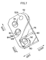
- a swinging plate 76 which is shaped as a substantially rectangular plate and serves as a swinging member, is disposed within each setting concave portion 70.
- a solid cylindrical supporting shaft 78 is provided at the reverse surface of the swinging plate 76 at the rear portion of the left side thereof.
- An accommodating recess 80 which is substantially rectangular parallelepiped, is formed in the front portion of the reverse surface of the swinging plate 76.
- the accommodating recess 80 has a left wall and a rear wall, and the right surface and front surface thereof are open.
- the adjustment pin 72 is accommodated in the accommodating recess 80.
- a cylindrical through hole 82 is formed in the reverse surface of the swinging plate 76 at the left side and at the intermediate portion in the front-back direction.
- a fixing screw 84 is disposed in the through hole 82.
- the fixing screw 84 has a solid cylindrical head portion 86 and a screw portion 88.
- the head portion 86 has a larger diameter than the through hole 82, and the screw portion 88 has a smaller diameter than the through hole 82.
- the fixing screw 84 is a right-handed screw. By turning the fixing screw 84 (the head portion 86) to the right (in one direction) in a state in which the screw portion 88 has been passed through the through hole 82, the screw portion 88 is fixed to the bottom surface of the setting concave portion 70.
- the swinging plate 76 is sandwiched between the head portion 86 and the rotating drum 50, and the swinging plate 76 is fixed to the rotating drum 50. Moreover, when the fixing screw 84 is rotated toward the right, the bottom surface of the head portion 86 contacts the swinging plate 76, and the swinging plate 76 is swung toward the right. In this way, the left wall of the accommodating recess 80 (a position separated from the supporting shaft 78 of the swinging plate 76) contacts the adjustment pin 72.
- the swung position of the swinging plate 76 at the time when the adjustment pin 72 and the swinging plate 76 contact one another, i.e., the position which the swinging plate 76 is swung to and disposed at, is different.
- a positioning pin 52 (a bearing in the present embodiment) serving as an abutment member is provided at the rear portion of the right side of the obverse of the swinging plate 76.
- the positioning pin 52 is shaped as a solid cylinder, and is freely rotatable around a central shaft 52A, and projects toward the rear from the swinging plate 76.
- the positioning pin 52 projects from the peripheral surface of the rotating drum 50.
- the position of the printing plate 12 in the front-back direction on the rotating drum 50 is determined by the front end of the printing plate 12, which has been conveyed onto the peripheral surface of the rotating drum 50, abutting the pair of positioning pins 52.
- the position of the printing plate 12 in the left-right direction is determined by the conveying pin 42 moving and the printing plate 12 abutting the reference pin 36 in the same way as described above. In this way, the printing plate 12 is actually positioned in the exposure section 18.
- a distance L1 which is between the center of swinging of the swinging plate 76 or the center of the supporting shaft 78 and the position at which the swinging plate 76 or the left wall of the accommodating recess 80 contacts the adjustment pin 72, is greater than a distance L2, which is between the center of swinging of the swinging plate 76 and the position of the positioning pin 52 abutted by the front end of the printing plate 12 (i.e., the rear end of the positioning pin 52).
- an angle ⁇ , with respect to the left-right direction, of a straight line 11, which passes through the center of rotation of the positioning pin 52 (i.e., the center of the central shaft 52A) and the center of the supporting shaft 78 which is the center of swinging of the swinging plate 76, is small.
- plate-shaped front end chucks 54 are provided at the peripheral surface of the rotating drum 50 in vicinities of the pair of positioning pins 52.
- the front end chucks 54 are supported at the rotating drum 50 so as to be freely rotatable. Elastic force in a direction of separating from the peripheral surface of the rotating drum 50 is applied to the front sides of the front end chucks 54.
- Attaching cams 56 are provided above the front end chucks 54. Due to the attaching cams 56 pressing the front sides of the front end chucks 54, the rear sides of the front end chucks 54 move apart from the peripheral surface of the rotating drum 50. In this way, the front end of the printing plate 12, which has been conveyed onto the peripheral surface of the rotating drum 50 from the plate supplying guide 20 as described above, is inserted between the peripheral surface of the rotating drum 50 and the rear sides of the front end chucks 54, and in this state, the above-described actual positioning of the printing plate 12 is carried out. Further, after the actual positioning of the printing plate 12 has been carried out, the attaching cams 56 are rotated such that their pressing of the front sides of the front end chucks 54 is released.
- the rear sides of the front end chucks 54 press the front end of the printing plate 12 due to the aforementioned elastic force, and the front end of the printing plate 12 is held at the peripheral surface of the rotating drum 50.
- the rotating drum 50 is rotated in the direction of arrow A in Fig. 5, and the printing plate 12 is wound on the peripheral surface of the rotating drum 50.
- a squeeze roller 58 is disposed in a vicinity of the peripheral surface of the rotating drum 50, further toward the front side of the exposure device 10 (i.e., further toward the side in the direction of arrow A in Fig. 5) than the attaching cams 56.
- the squeeze roller 58 By moving the squeeze roller 58 toward the rotating drum 50, the printing plate 12 wound around the rotating drum 50 is rotated while being pressed against the rotating drum 50, and is closely contacts the peripheral surface of the rotating drum 50.
- a rear end chuck attaching/removing unit 60 is disposed in a vicinity of the peripheral surface of the rotating drum 50, between the attaching cams 56 and the squeeze roller 58.
- the rear end chuck attaching/removing unit 60 has shafts 62.
- the shafts 62 can move toward the rotating drum 50.
- Rear end chucks 64 are attached to the distal ends of the shafts 62.
- the shafts 62 move the rear end chucks 64 toward the rotating drum 50, and attach the rear end chucks 64 to predetermined positions of the rotating drum 50.
- the rear end chucks 64 are separated from the shafts 62. In this way, the rear end chucks 64 press the rear end of the printing plate 12, such that the rear end of the printing plate 12 is held at the peripheral surface of the rotating drum 50.
- the squeeze roller 58 is moved away from the rotating drum 50. Thereafter, the rotating drum 50 is rotated at high speed at a predetermined rotational speed.
- a recording head portion 66 is disposed in a vicinity of the peripheral surface of the rotating drum 50. Synchronously with the rotation of the rotating drum 50, the recording head portion 66 emits, toward the rotating drum 50 which is rotating at high speed, a light beam which has been modulated on the basis of read image data. In this way, the printing plate 12 is exposed on the basis of the image data.
- This exposure processing is scan-exposure in which the recording head portion 66 is moved along the axial direction of the rotating drum 50 (sub-scanning) while the rotating drum 50 is rotated at high speed (main scanning).
- the rotating drum 50 is temporarily stopped at a position at which the rear end chucks 64 oppose the shafts 62, and the rear end chucks 64 are removed from the rotating drum 50 by the shafts 62. Namely, the rear end chucks 64 are attached to the shafts 62, and the pressing of the rear end of the printing plate 12 by the rear end chucks 64 is cancelled. Moreover, after the conveying guide unit 14 is rotated such that the plate discharging guide 22 corresponds to the exposure section 18 (i.e., such that the plate discharging guide 22 opposes the rotating drum 50 in a direction tangential to the rotating drum 50), the rotating drum 50 is rotated in the direction of arrow B in Fig. 5.
- the printing plate 12 is discharged out to the plate discharging guide 22 from the rear end side of the printing plate 12.
- the attaching cams 56 such that the attaching cams 56 press the front sides of the front end chucks 54
- the pressing of the front end of the printing plate 12 by the front end chucks 54 is released.
- the conveying guide unit 14 is rotated, and the printing plate 12 is discharged from the plate discharging guide 22.
- the printing plate 12 is conveyed to a developing device or a printing device (neither of which is illustrated) which is the subsequent process adjacent to the automatic printing plate exposure device 10.
- the printing plate 12 is placed on the plate supplying guide 20.
- the printing plate 12 may be fed in by manual feeding, or by an automatic sheet-feeding device, or the like.
- the printing plate 12 on the plate supplying guide 20 is in a state in which the position at which the printing plate 12 is placed, the inclination of the printing plate 12 with respect to the plate supplying guide 20, and the like thereof are relatively rough.
- the printing plate 12 is conveyed forward by the conveying roller 24, the front end of the printing plate 12 abuts the pair of positioning pins 30, and the conveying pin 42 is moved such that the printing plate 12 is made to abut the reference pin 36.
- the printing plate 12 is thereby temporarily positioned.
- the conveying guide unit 14 is rotated such that the plate supplying guide 20 is made to correspond to the puncher section 16.
- the pair of positioning pins 30 are lowered from the top surface of the plate supplying guide 20, and the printing plate 12 is conveyed forward by the conveying roller 24 such that the front end of the printing plate 12 abuts the pair of positioning pins 48 of the puncher section 16.
- the conveying pin 42 being moved such that the printing plate 12 is made to abut the reference pin 36, the printing plate 12 is actually positioned in the puncher section 16.
- a predetermined number of punch holes are formed by the punching devices 46 in the front end of the printing plate 12 which is actually positioned in this way.
- the printing plate 12 is returned onto the plate supplying guide 20 due to reverse rotation of the conveying roller 24.
- the pair of positioning pins 30 are made to project from the top surface of the plate supplying guide 20, and the printing plate 12 is again temporarily positioned in the same way as described above.
- the conveying guide unit 14 is rotated such that the plate supplying guide 20 is made to correspond to the exposure section 18.
- the printing plate 12 is conveyed forward by the conveying roller 24 such that the front end of the printing plate 12 abuts the pair of positioning pins 52 of the rotating drum 50. Due to the conveying pin 42 moving such that the printing plate 12 is made to abut the reference pin 36, the printing plate 12 is actually positioned in the exposure section 18.
- the printing plate 12 While the front end and the rear end of the printing plate 12, which has been actually positioned in this way, are held at the peripheral surface of the rotating drum 50 by the front end chucks 54 and the rear end chucks 64, respectively, and the printing plate 12 is closely contacted against the peripheral surface of the rotating drum 50 by the squeeze roller 58, the printing plate 12 is wound around the peripheral surface of the rotating drum 50. Thereafter, the rotating drum 50 is rotated at high speed, and exposure processing is carried out by the recording head portion 66.
- the conveying guide unit 14 When exposure processing has been completed, the conveying guide unit 14 is rotated such that the plate discharging guide 22 is made to correspond to the rotating drum 50. While the holding of the printing plate 12 at the peripheral surface of the rotating drum 50 by the front end chucks 54 and the rear end chucks 64 is released, the printing plate 12 is discharged from the rotating drum 50 to the plate discharging guide 22. Thereafter, the conveying guide unit 14 is rotated, and the printing plate 12 is conveyed from the plate discharging guide 22 to the developing device or the printing device.
- the printing plate 12 is positioned in the front-back direction due to the front end of the printing plate 12, which is placed on the rotating drum 50 in the exposure section 18, abutting the pair of positioning pins 52.
- the positioning pin 52 is provided at the swinging plate 76 which is provided at the rotating drum 50.
- the positioning pin 52 is disposed at a position away from the center of swinging of the swinging plate 76, i.e., away from the center of the supporting shaft 78.
- the adjustment pin 72 provided at the rotating drum 50 contacts the swinging plate 76 at a position which is separated from the center of swinging thereof, i.e., at the left wall of the accommodating recess 80.
- the adjustment pin 72 which mounts the mounting shaft 74 in the mounting hole of the setting concave portion 70 i.e., by replacing the adjustment pin 72 with an adjustment pin 72 of a different diameter
- the swung position of the swinging plate 76 at the time when the swinging plate 76 and the adjustment pin 72 contact one another is adjusted.
- the rotational position of the positioning pin 52 around the center of swinging of the swinging plate 76 can be adjusted, and adjustment or fine adjustment of the position of the positioning pin 52 with respect to the rotating drum 50 can be carried out.
- the position of the positioning pin 52 with respect to the rotating drum 50 can be adjusted merely by adjusting the swung position of the swinging plate 76 at the time the swinging plate 76 and the adjustment pin 72 contact one another, by changing the adjustment pin 72.
- the mechanism for adjusting the position of the positioning pin 52 with respect to the rotating drum 50 can be made to be a sufficiently simple structure, and this mechanism can thereby be made to be satisfactorily compact and lightweight. Accordingly, when the printing plate 12 is subjected to exposure processing, even if the rotating drum 50 is rotated at high speed, deformation of the rotating drum 50 due to centrifugal force can be suppressed. In this way, it is possible to suppress changing of the distance between the recording head portion 66 and the printing plate 12 and the occurrence of blurring in the recorded image.
- the swinging plate 76 is fixed to the rotating drum 50, and the swinging plate 76 is swung to the right, and the left wall of the accommodating recess 80 contacts the adjustment pin 72.
- the swinging plate 76 is fixed to the rotating drum 50 and the position of the positioning pin 52 is fixed, it is possible to prevent a gap from arising between the swinging plate 76 and the adjustment pin 72, and to reliably adjust the position of the positioning pin 52.
- the distance L1 which is between the center of swinging of the swinging plate 76 and the position at which the swinging plate 76 contacts the adjustment pin 72, is greater than the distance L2, which is between the center of swinging of the swinging plate 76 and the position of the positioning pin 52 abutted by the printing plate 12 (i.e., the rear end of the positioning pin 52).
- the rotational distance of the positioning pin 52 at the position thereof which the printing plate 12 abuts is smaller than the swinging distance of the swinging plate 76 at the position thereof contacting the adjustment pin 72. Therefore, as shown in Fig. 6, the resolution of the position of the positioning pin 52 can be made to be higher than the adjusted resolution of the swung position of the swinging plate 76 due to changing of the diameter of the adjustment pin 72. The position of the positioning pin 52 can thereby be adjusted with high accuracy.
- the straight line 12 which passes through the position of the positioning pin 52 abutted by the printing plate 12 and the center of swinging of the swinging plate 76, approaches a direction perpendicular with respect to the direction (the front-back direction) of positioning the printing plate 12 by the positioning pins 52.
- the direction of adjustment of the position of the positioning pin 52 abutted by the printing plate 12 approaches a direction parallel to the direction of positioning the printing plate 12 by the positioning pins 52.
- the amount of adjustment of the position of the positioning pin 52 abutted by the printing plate 12 can be made to approach a state proportional to the amount of adjustment of the swung position of the swinging pin 76 by changing the diameter of the adjustment pin 72. (Namely, the linearity of the both amounts of adjustment can be increased.) Accordingly, the position of the positioning pin 52 can be adjusted easily.
- the swung position of the swinging plate 76 at the time when the swinging plate 76 and the adjustment pin 72 contact one another is adjusted by, as the adjusting means, changing the diameter of the adjustment pin 72 by changing the adjustment pin 72 which mounts the mounting shaft 74 to the mounting hole of the setting concave portion 70.
- a cam member may be used as the adjusting means.
- a solid cylindrical mounting shaft 92 may be integrally provided at the bottom surface of an adjustment pin 90 at a position which is offset from the center, and the mounting shaft 92 may be mounted into the mounting hole of the setting concave portion 70.
- the positioning pins 30, 48, 52 are respectively provided as pairs of positioning pins.
- the positioning pins 30, 48, 52 may be formed by a combination of four pins: a pair of pins for large-sized printing plates 12 and a pair of pins for small-sized printing plates 12. re may be four of each of these positioning pins 30, 48, 52, with a pair of the positioning pins 30, 48, 52, respectively, being provided for large-sized printing plates 12 and a pair of the positioning pins 30, 48, 52, respectively, being provided for small-sized printing plates 12.
- the present invention is applied to the positioning pin 52.
- the present invention may be applied to the positioning pins 30 or the positioning pins 48, or may be applied to the reference pin 36 or the conveying pin 42 as well.
- the present invention is applied to the outer-drum-type automatic printing plate exposure device 10.
- the present invention may also be applied to a flatbed-type or an inner-drum-type automatic printing plate exposure device.
- a sheet material is positioned by the sheet material abutting an abutment member.
- the swung position of the swinging member at the time when the swinging member and the contact member contact one another is adjusted by the adjusting means.
- the rotational position of the abutment member can be adjusted, and the position of the abutment member with respect to the placement member can be adjusted.
- the position of the abutment member with respect to the placement member can be adjusted merely by the adjusting means adjusting the swung position of the swinging member at the time when the swinging member and the contact member contact one another. Therefore, the mechanism which adjusts the position of the abutment member with respect to the placement member can be made to be compact and lightweight.
Landscapes
- Engineering & Computer Science (AREA)
- Mechanical Engineering (AREA)
- Manufacturing & Machinery (AREA)
- Registering Or Overturning Sheets (AREA)
- Exposure And Positioning Against Photoresist Photosensitive Materials (AREA)
Abstract
Description
Claims (10)
- A sheet material positioning device comprising:a swinging member swingably provided at a placement member onto which a sheet material is conveyed and mounted; andan abutment member provided at the swinging member so as to be positioned on a conveying path of the sheet material, and positioning the sheet material by the sheet material and the abutment member abutting each other.
- The sheet material positioning device of claim 1, further comprising adjusting means for adjusting a position of the abutment member by swinging the swinging member.
- The sheet material positioning device of claim 2, wherein the adjusting means swings the swinging member by abutting the swinging member.
- The sheet material positioning device of claim 2 or claim 3, wherein the adjusting means is structured such that an amount of movement the abutment member moves due to the swinging member swinging is smaller than an amount of swinging the swinging member is swung.
- The sheet material positioning device of any of claims 2 through 4, wherein a distance between a position, at which the swinging member and the adjusting means abut one another and a center of swinging of the swinging member, is greater than a distance between a position of the abutment member, which the sheet material abuts, and the center of swinging of the swinging member.
- The sheet material positioning device of any of claims 2 through 5, wherein the adjusting means is structured so as to be able to selectively mount a plurality of contact members having respectively different sizes.
- The sheet material positioning device of any of claims 2 through 5, wherein the adjusting means is structured so as to be rotatably provided at the placement member and such that a center of rotation of the adjusting means is eccentric.
- The sheet material positioning device of any of claims 2 through 7, wherein the abutment member is provided integrally with the swinging member.
- A method of adjusting a position of a sheet material by an abutment member provided at a swinging member, the method comprising the steps of:a) swinging the swinging member to a predetermined position by making the swinging member abut an adjusting means; andb) fixing the abutment member at a predetermined position by the swinging of the swinging member.
- The method of adjusting of claim 9, wherein the abutment member is moved to the predetermined position on the basis of a predetermined relationship between an amount of adjustment of the adjusting means and an amount of movement of a position of the abutment member.
Applications Claiming Priority (2)
| Application Number | Priority Date | Filing Date | Title |
|---|---|---|---|
| JP2002088859 | 2002-03-27 | ||
| JP2002088859A JP3711080B2 (en) | 2002-03-27 | 2002-03-27 | Sheet material positioning device |
Publications (2)
| Publication Number | Publication Date |
|---|---|
| EP1357071A2 true EP1357071A2 (en) | 2003-10-29 |
| EP1357071A3 EP1357071A3 (en) | 2005-04-13 |
Family
ID=28786133
Family Applications (1)
| Application Number | Title | Priority Date | Filing Date |
|---|---|---|---|
| EP03006800A Withdrawn EP1357071A3 (en) | 2002-03-27 | 2003-03-26 | Sheet material positioning device |
Country Status (2)
| Country | Link |
|---|---|
| EP (1) | EP1357071A3 (en) |
| JP (1) | JP3711080B2 (en) |
Cited By (2)
| Publication number | Priority date | Publication date | Assignee | Title |
|---|---|---|---|---|
| WO2010047747A1 (en) * | 2008-10-23 | 2010-04-29 | Eastman Kodak Company | Moveable printing plate registration member |
| WO2010047782A1 (en) * | 2008-10-23 | 2010-04-29 | Eastman Kodak Company | Moveable printing plate registration member |
Family Cites Families (8)
| Publication number | Priority date | Publication date | Assignee | Title |
|---|---|---|---|---|
| DE69225201T2 (en) * | 1991-12-03 | 1998-08-13 | Crown Cork & Seal Co | Method and device for printing multicolored blanks for container sleeves in a single pass |
| DE4306237A1 (en) * | 1993-02-27 | 1994-09-01 | Heidelberger Druckmasch Ag | Device for setting the inclined register in a clamping device for clamping printing plates in an offset printing machine |
| DE9310987U1 (en) * | 1993-07-22 | 1993-08-26 | Man Roland Druckmaschinen Ag, 63069 Offenbach | Device for registering printing plates on the plate cylinder of printing machines |
| DE4340052C2 (en) * | 1993-11-24 | 1996-06-13 | Roland Man Druckmasch | Device for checking the registration of a printing plate on a plate cylinder of a printing press |
| IL120138A (en) * | 1997-02-03 | 2001-07-24 | Creoscitex Corp Ltd | Method for recording a rectangular image |
| JP2000302795A (en) * | 1999-04-20 | 2000-10-31 | Nihon Medi Physics Co Ltd | Fatty acid derivatives labeled with radioactive transition metals |
| DE19948878A1 (en) * | 1999-10-08 | 2001-04-12 | Wilfried Jeurink E Kfm | Printing cylinders, in particular for multi-color letterpress printing |
| US6604465B2 (en) * | 2000-02-25 | 2003-08-12 | Agfa Corporation | Pin registration system for mounting different width printing plates |
-
2002
- 2002-03-27 JP JP2002088859A patent/JP3711080B2/en not_active Expired - Fee Related
-
2003
- 2003-03-26 EP EP03006800A patent/EP1357071A3/en not_active Withdrawn
Cited By (6)
| Publication number | Priority date | Publication date | Assignee | Title |
|---|---|---|---|---|
| WO2010047747A1 (en) * | 2008-10-23 | 2010-04-29 | Eastman Kodak Company | Moveable printing plate registration member |
| WO2010047782A1 (en) * | 2008-10-23 | 2010-04-29 | Eastman Kodak Company | Moveable printing plate registration member |
| CN102171041A (en) * | 2008-10-23 | 2011-08-31 | 伊斯曼柯达公司 | Movable printing plate registration member |
| US8176846B2 (en) | 2008-10-23 | 2012-05-15 | Eastman Kodak Company | Printing plate positioning |
| US8210104B2 (en) | 2008-10-23 | 2012-07-03 | Eastman Kodak Company | Moveable printing plate registration member |
| CN102171041B (en) * | 2008-10-23 | 2015-03-11 | 伊斯曼柯达公司 | Moveable printing plate registration member |
Also Published As
| Publication number | Publication date |
|---|---|
| EP1357071A3 (en) | 2005-04-13 |
| JP2003276908A (en) | 2003-10-02 |
| JP3711080B2 (en) | 2005-10-26 |
Similar Documents
| Publication | Publication Date | Title |
|---|---|---|
| US6856334B1 (en) | Sheet material fixing device | |
| US4464042A (en) | Device for guiding a recording paper | |
| EP1306331B1 (en) | Sheet member positioning device | |
| CN1576039A (en) | Sheet conveying apparatus and image forming apparatus and image reading device | |
| JP2012506789A (en) | Movable printing plate posture correction member | |
| US6712003B2 (en) | Sheet member positioning device and image recording device | |
| EP1357071A2 (en) | Sheet material positioning device | |
| US6865987B2 (en) | Sheet-shaped material positioning device and printing plate precursor exposure device | |
| US6559880B2 (en) | Scan-exposure device | |
| US6772691B2 (en) | System and method for registering media in an imaging system | |
| JP4340408B2 (en) | Sheet material positioning device | |
| US6752080B2 (en) | Sheet material holding device | |
| US8155561B2 (en) | Image forming apparatus | |
| US6664999B2 (en) | Image-recording device and method | |
| JP2003337429A (en) | Image recorder | |
| JP2003072989A (en) | Sheet material positioning equipment | |
| US20040253005A1 (en) | Sheet body holding device | |
| JP2004217339A (en) | Conveyance device | |
| JP2003231297A (en) | Image recorder | |
| JP2003095485A (en) | Sheet material positioning device | |
| JP2004004416A (en) | Sheet material fixing device | |
| JPH02282135A (en) | Guide device of recording medium | |
| JP2003173030A (en) | Image forming device | |
| JP2003095476A (en) | Sheet material carrying device | |
| JP2004091209A (en) | Sheet material positioning device |
Legal Events
| Date | Code | Title | Description |
|---|---|---|---|
| PUAI | Public reference made under article 153(3) epc to a published international application that has entered the european phase |
Free format text: ORIGINAL CODE: 0009012 |
|
| AK | Designated contracting states |
Kind code of ref document: A2 Designated state(s): AT BE BG CH CY CZ DE DK EE ES FI FR GB GR HU IE IT LI LU MC NL PT SE SI SK TR |
|
| AX | Request for extension of the european patent |
Extension state: AL LT LV MK RO |
|
| PUAL | Search report despatched |
Free format text: ORIGINAL CODE: 0009013 |
|
| AK | Designated contracting states |
Kind code of ref document: A3 Designated state(s): AT BE BG CH CY CZ DE DK EE ES FI FR GB GR HU IE IT LI LU MC NL PT SE SI SK TR |
|
| AX | Request for extension of the european patent |
Extension state: AL LT LV MK RO |
|
| 17P | Request for examination filed |
Effective date: 20051011 |
|
| AKX | Designation fees paid |
Designated state(s): DE FR GB |
|
| 17Q | First examination report despatched |
Effective date: 20060102 |
|
| RAP1 | Party data changed (applicant data changed or rights of an application transferred) |
Owner name: FUJIFILM CORPORATION |
|
| GRAP | Despatch of communication of intention to grant a patent |
Free format text: ORIGINAL CODE: EPIDOSNIGR1 |
|
| STAA | Information on the status of an ep patent application or granted ep patent |
Free format text: STATUS: THE APPLICATION IS DEEMED TO BE WITHDRAWN |
|
| 18D | Application deemed to be withdrawn |
Effective date: 20071011 |