EP1357015A2 - A dual resolver device - Google Patents

A dual resolver device Download PDF

Info

Publication number
EP1357015A2
EP1357015A2 EP03006477A EP03006477A EP1357015A2 EP 1357015 A2 EP1357015 A2 EP 1357015A2 EP 03006477 A EP03006477 A EP 03006477A EP 03006477 A EP03006477 A EP 03006477A EP 1357015 A2 EP1357015 A2 EP 1357015A2
Authority
EP
European Patent Office
Prior art keywords
shaft
resolver
rotation angle
dual
angle
Prior art date
Legal status (The legal status is an assumption and is not a legal conclusion. Google has not performed a legal analysis and makes no representation as to the accuracy of the status listed.)
Withdrawn
Application number
EP03006477A
Other languages
German (de)
French (fr)
Other versions
EP1357015A3 (en
Inventor
Matsuura Mutsumi
Miya Taiichi
Current Assignee (The listed assignees may be inaccurate. Google has not performed a legal analysis and makes no representation or warranty as to the accuracy of the list.)
Minebea Co Ltd
Original Assignee
Minebea Co Ltd
Priority date (The priority date is an assumption and is not a legal conclusion. Google has not performed a legal analysis and makes no representation as to the accuracy of the date listed.)
Filing date
Publication date
Application filed by Minebea Co Ltd filed Critical Minebea Co Ltd
Publication of EP1357015A2 publication Critical patent/EP1357015A2/en
Publication of EP1357015A3 publication Critical patent/EP1357015A3/en
Withdrawn legal-status Critical Current

Links

Images

Classifications

    • BPERFORMING OPERATIONS; TRANSPORTING
    • B62LAND VEHICLES FOR TRAVELLING OTHERWISE THAN ON RAILS
    • B62DMOTOR VEHICLES; TRAILERS
    • B62D6/00Arrangements for automatically controlling steering depending on driving conditions sensed and responded to, e.g. control circuits
    • B62D6/08Arrangements for automatically controlling steering depending on driving conditions sensed and responded to, e.g. control circuits responsive only to driver input torque
    • B62D6/10Arrangements for automatically controlling steering depending on driving conditions sensed and responded to, e.g. control circuits responsive only to driver input torque characterised by means for sensing or determining torque
    • BPERFORMING OPERATIONS; TRANSPORTING
    • B62LAND VEHICLES FOR TRAVELLING OTHERWISE THAN ON RAILS
    • B62DMOTOR VEHICLES; TRAILERS
    • B62D15/00Steering not otherwise provided for
    • B62D15/02Steering position indicators ; Steering position determination; Steering aids
    • B62D15/021Determination of steering angle
    • B62D15/0245Means or methods for determination of the central position of the steering system, e.g. straight ahead position
    • GPHYSICS
    • G01MEASURING; TESTING
    • G01DMEASURING NOT SPECIALLY ADAPTED FOR A SPECIFIC VARIABLE; ARRANGEMENTS FOR MEASURING TWO OR MORE VARIABLES NOT COVERED IN A SINGLE OTHER SUBCLASS; TARIFF METERING APPARATUS; MEASURING OR TESTING NOT OTHERWISE PROVIDED FOR
    • G01D5/00Mechanical means for transferring the output of a sensing member; Means for converting the output of a sensing member to another variable where the form or nature of the sensing member does not constrain the means for converting; Transducers not specially adapted for a specific variable
    • G01D5/12Mechanical means for transferring the output of a sensing member; Means for converting the output of a sensing member to another variable where the form or nature of the sensing member does not constrain the means for converting; Transducers not specially adapted for a specific variable using electric or magnetic means
    • G01D5/14Mechanical means for transferring the output of a sensing member; Means for converting the output of a sensing member to another variable where the form or nature of the sensing member does not constrain the means for converting; Transducers not specially adapted for a specific variable using electric or magnetic means influencing the magnitude of a current or voltage
    • G01D5/20Mechanical means for transferring the output of a sensing member; Means for converting the output of a sensing member to another variable where the form or nature of the sensing member does not constrain the means for converting; Transducers not specially adapted for a specific variable using electric or magnetic means influencing the magnitude of a current or voltage by varying inductance, e.g. by a movable armature
    • G01D5/204Mechanical means for transferring the output of a sensing member; Means for converting the output of a sensing member to another variable where the form or nature of the sensing member does not constrain the means for converting; Transducers not specially adapted for a specific variable using electric or magnetic means influencing the magnitude of a current or voltage by varying inductance, e.g. by a movable armature by influencing the mutual induction between two or more coils
    • G01D5/2046Mechanical means for transferring the output of a sensing member; Means for converting the output of a sensing member to another variable where the form or nature of the sensing member does not constrain the means for converting; Transducers not specially adapted for a specific variable using electric or magnetic means influencing the magnitude of a current or voltage by varying inductance, e.g. by a movable armature by influencing the mutual induction between two or more coils by a movable ferromagnetic element, e.g. a core
    • GPHYSICS
    • G01MEASURING; TESTING
    • G01LMEASURING FORCE, STRESS, TORQUE, WORK, MECHANICAL POWER, MECHANICAL EFFICIENCY, OR FLUID PRESSURE
    • G01L3/00Measuring torque, work, mechanical power, or mechanical efficiency, in general
    • G01L3/02Rotary-transmission dynamometers
    • G01L3/04Rotary-transmission dynamometers wherein the torque-transmitting element comprises a torsionally-flexible shaft
    • G01L3/10Rotary-transmission dynamometers wherein the torque-transmitting element comprises a torsionally-flexible shaft involving electric or magnetic means for indicating
    • G01L3/101Rotary-transmission dynamometers wherein the torque-transmitting element comprises a torsionally-flexible shaft involving electric or magnetic means for indicating involving magnetic or electromagnetic means
    • G01L3/105Rotary-transmission dynamometers wherein the torque-transmitting element comprises a torsionally-flexible shaft involving electric or magnetic means for indicating involving magnetic or electromagnetic means involving inductive means
    • GPHYSICS
    • G01MEASURING; TESTING
    • G01LMEASURING FORCE, STRESS, TORQUE, WORK, MECHANICAL POWER, MECHANICAL EFFICIENCY, OR FLUID PRESSURE
    • G01L3/00Measuring torque, work, mechanical power, or mechanical efficiency, in general
    • G01L3/02Rotary-transmission dynamometers
    • G01L3/04Rotary-transmission dynamometers wherein the torque-transmitting element comprises a torsionally-flexible shaft
    • G01L3/10Rotary-transmission dynamometers wherein the torque-transmitting element comprises a torsionally-flexible shaft involving electric or magnetic means for indicating
    • G01L3/109Rotary-transmission dynamometers wherein the torque-transmitting element comprises a torsionally-flexible shaft involving electric or magnetic means for indicating involving measuring phase difference of two signals or pulse trains

Definitions

  • road vehicles such as automobiles are steered by means of an operator (driver) rotating a steering wheel (handwheel), which, in turn, causes rotation of wheels (roadwheels) that are in contact with a road surface.
  • the roadwheels are operatively coupled to the handwheel via a steering shaft. Due to frictional forces between the roadwheels and the road surface, the roadwheels generally do not rotate to the same extent as the steering wheel rotates. Consequently, more than one turn ( i . e ., complete revolution) of the handwheel is generally needed in order to move the roadwheels from lock to lock.
  • Torque sensors have been developed to measure the difference in rotation angles between the handwheel and the roadwheels. Electric power assisted steering systems that incorporate torque sensors have been developed to provide servo control of the steering system in order to minimize the difference in rotation angles between the handwheel and roadwheels, and thereby optimize steering accuracy.
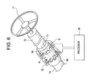
  • Figure 6 illustrates a torque sensor of a previously-developed electric power assisted vehicle steering system.
  • the system includes, at one end, an input shaft 72 operatively connected to a steering wheel or handwheel 71, and, at the other end, an output shaft 74 operatively connected to at least one roadwheel (not shown).
  • the input shaft 72 and the output shaft 74 are linked by a torsion bar 73 that twists when the handwheel 71 is turned, during steering, by an amount that depends upon the amount of torque generated by the turning action.
  • a first detection ring 66 is installed around the outer surface of the input shaft 72 and rotates by approximately the same angle as the handwheel 71.
  • a second detection ring 67 is installed around the outer surface of the torsion bar 73.
  • a third detection ring 68 is installed around the outer surface of the output shaft 74 and rotates by approximately the same angle as the roadwheels.
  • the detection rings 66-68 are composed of magnetic material.
  • Toothed portions comprised of spaced-apart teeth are formed on mutually opposing surfaces of the first and second detection rings 66, 67, and similar toothed portions are formed on mutually opposing surfaces of the second and third detection rings 67, 68.
  • a first coil 61 is wound around the outer surface of the first detection ring 66 and the second detection ring 67. The first coil 61 extends across a gap between the first and second detection rings 66, 67.
  • a second coil 70 is wound around the outer surface of the third detection ring 68 and the second detection ring 67. The second coil 70 extends across a gap between the third and second detection rings 68, 67.
  • the first and second coils 61, 70 are each operatively connected to a processor 69.
  • the above-described torque sensor of the previously-developed electric power assisted vehicle steering system works as follows.
  • the input shaft 72, output shaft 74 and torsion bar 73 also rotate.
  • one end portion of the torsion bar 73 which is joined to the input shaft 72 ( i . e ., steering wheel side)
  • the output shaft 74 i.e ., the roadwheel side.
  • the rotation angles of the first, second, and third detection rings have the following relationship: rotation angle of first detection ring 66 > rotation angle of second detection ring 67 > rotation angle of third detection ring 68.
  • the inductance values of the first coil 61 and the second coil 70 are set to be the same, so that when the steering wheel 71 is rotated, the magnetic flux sensed by the first coil 61 is constant, whereas the magnetic flux sensed by the second coil 70 varies.
  • Figure 7 illustrates a resolver of a previously-developed electric power assisted vehicle steering system.
  • the resolver depicted in Figure 7 operates on the principle of a rotary transformer.
  • this resolver includes a rotary shaft 50, a rotor 54 mounted to the rotary shaft 50, a resolver excitation winding 58 wound around the rotor 54, an inner core 56, and a rotary transformer output winding 60 wound around the inner core 56.
  • the rotor 54 and its associated components are mounted for rotational movement along with rotary shaft 50, within a case 52, by means of bearings 51A and 51B.
  • the system further includes a stator 53, a resolver output winding 57 wound around the stator 53, an outer core 55, and a rotary transformer excitation winding 59 wound around the outer core 55.
  • the stator 53 and its associated components are fixedly mounted to the case 52, so as to remain stationary during rotational movement of the rotary shaft 50.
  • An excitation voltage applied to the rotary transformer excitation winding 59 induces a voltage in the rotary transformer output winding 60 through the action of the rotary transformer formed by the outer core 55 and the inner core 56.
  • the voltage induced in the rotary transformer output winding 60 is applied to the resolver excitation winding 58.
  • the X-axis (X) and Y-axis (Y) components of the rotation angle of the rotary shaft 50 can be determined from the output of the resolver output winding 57.
  • both of the above-described previously-developed systems suffer from the common limitation that they are capable of measuring only the rotation deviation angle (relative rotation angle) of the rotary shaft, and are not capable of measuring the absolute rotation angle of the rotary shaft, and thus, are not capable of ascertaining the absolute position of the roadwheels.
  • the present invention encompasses, among other things, a dual resolver device that includes a first resolver having a first rotary shaft, and a second resolver having a second rotary shaft, wherein the absolute value of a difference between a shaft angle multiple of the first resolver and a shaft angle multiple of the second resolver is 1.
  • the dual resolver device further includes a torsion bar connecting the first and second rotary shafts.
  • the first and second rotary shafts constitute different portions of the same rotary shaft.
  • the first resolver preferably produces an output indicative of a rotation angle of the first rotary shaft
  • the second resolver preferably produces an output indicative of a rotation angle of the second rotary shaft.
  • the dual resolver device preferably further includes a processor that determines an absolute shaft rotation angle in response to the first and second outputs, and the shaft angle multiples of the first and second resolvers.
  • the processor has the capability of determining both the absolute and relative shaft rotation angles in response to the first and second outputs, and the shaft angle multiples of the first and second resolvers.
  • the sum of the shaft angle multiples is preferably ⁇ 3, and, in an illustrative embodiment, is ⁇ 11.
  • Figure 1 is a block diagram of a dual resolver of a shaft angle measurement device according to one embodiment of the present invention
  • Figure 2 is a block diagram of a dual resolver of a shaft angle measurement device according to another embodiment of the present invention.
  • Figure 3 is a graphical representation of equation (14) including a set of graphs corresponding to different parametric conditions;
  • Figure 4 is a table depicting the value of ⁇ for different values of P and Q with respect to equation (14);
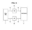
  • Figure 5 is a block diagram of a shaft angle measurement device according to an embodiment of the present invention.
  • Figure 6 is a perspective, partial cross-section view of a torque sensor of a previously-developed electric power assisted vehicle steering system.
  • Figure 7 is a perspective, partial cross-section view of a resolver of a previously-developed electric power assisted vehicle steering system.
  • first and second embodiments of a dual or twin resolver 1, respectively, are depicted diagrammatically.
  • the dual resolver 1 includes resolvers 2 and 4 that share a common rotary shaft 3.
  • the dual resolver 1 includes separate rotary shafts 3 and 5 for the resolvers 2 and 4, respectively, wherein the rotary shafts 3 and 5 of the resolvers 2 and 4 are connected by a torsion bar 7.
  • Resolvers 2 and 4 are suitably of a conventional type well-known in the art. As is well-known to those having ordinary skill in the pertinent art, such conventional resolvers have excitation and output windings, and produce outputs proportional to the sine and cosine of the rotation angle of a rotor. Such conventional resolvers also include an R/D (resolver/digital) converter that produces an output indicative of the respective rotation angle of the rotor of the respective resolver. As shown in Figures 1 and 2, the outputs of the R/D converter of the resolvers 2 and 4 are respectively designated ⁇ p and ⁇ q. Alternatively, the R/D converters can be implemented as separate components of a shaft angle measurement device incorporating the dual resolver 1, as will become apparent hereinafter.
  • shaft angle multiple refers to 1/2 the number of poles of the resolver.
  • the shaft angle multiples of resolver 2 and resolver 4 are referred to herein as P and Q, respectively.
  • the rotation angles of the rotary shafts 3 and 5 of resolvers 2 and 4, respectively, and the respective output rotation angles produced by the R/D converter of the resolvers 2 and 4, are set to ⁇ p and ⁇ q, respectively.
  • the rotation angle ⁇ + ⁇ of the rotary shaft 5 is expressed by equation (2) when the output rotation angle of resolver 4 with shaft angle multiple Q is ⁇ q, and a shaft rotation angle difference ⁇ is produced by twisting of the torsion bar 7.
  • Equation (3) The relationship between the output rotation angles ⁇ q and6p is determined as follows.
  • equation (14) In order to uniquely establish equation (14), it is necessary that equation (14) not change according to the values of the respective variables.
  • Figure 3 is a drawing that graphs equation (14) in order to facilitate an understanding thereof.
  • ⁇ p and ⁇ q are plotted on the horizontal axis and the vertical axis, respectively, with respect to the parameters M and (Q * ⁇ ) .
  • equation (15) does not impose any restriction on the relative size relationship of the shaft angle multiples P and Q of the resolvers 2 and 4. Accordingly, the shaft angle multiple of either resolver 2 or resolver 4 may be larger, and the difference between them need only satisfy equation (8), in order to uniquely establish equation (14) and facilitate determination of the absolute rotation angle ⁇ .
  • Figure 4 is a table which sets forth the ⁇ accuracy or resolution of the dual resolver 1 of the present invention, as determined by equation (15), for different values of P and Q that satisfy the condition of equation (8).
  • accuracy or resolution
  • resolver measurement accuracy or resolution becomes greater the larger the shaft angle multiple. Therefore, in order to achieve a resolver measurement range of 5 degrees (or greater) for ⁇ , it is optimal for there to be a combination of P and Q values of 6 and 5 (or 5 and 6), respectively.
  • the optimal values of P and Q will depend upon the parameters and/or requirements of any given application, such as the ⁇ parameter of the given application.
  • the particular values of P and Q that are chosen are not limiting to the present invention, in its broader aspects.
  • the optimal P and Q values may be 10 and 9 (or 9 and 10), respectively.
  • the measurement accuracy or resolution of the resolver is commensurately greater than the illustrative case discussed above in which the P and Q values are 6 and 5 (or 5 and 6), respectively, but at the expense of a narrower resolver measurement range ( i.e ., 2 degrees versus 6 degrees).
  • FIG. 5 there can be seen a functional block diagram of a shaft angle measurement device, according to an embodiment of the present invention, that incorporates the dual resolver 1 described hereinabove.
  • the shaft angle measurement apparatus of the present invention is capable of measuring both the absolute rotation angle ⁇ and the relative rotation angle ⁇ .
  • the illustrative embodiment of the shaft angle measurement device of the present invention includes the dual resolver 1 producing shaft angle outputs 1a ( ⁇ p) and 1b ( ⁇ q); R/D converters 5A and 5B which receive and digitize the shaft angle outputs 1a and 1b of the resolver 1, respectively, and produce digital shaft angle outputs 5a, 5b (if necessary); and, a processor 6 which receives the digital shaft angle outputs 5a, 5b of the R/D converters 5A, 5B, respectively, and which determines the absolute shaft rotation angle ⁇ and the relative shaft rotation angle ⁇ of the dual resolver 1, in a manner described below.
  • the R/D converters 5A and 5B and/or the processor 6 can be implemented as components of the dual resolver 1, or, alternatively, can be implemented as separate components of the shaft angle measurement device, either contained in the same or different housings.
  • the processor 6 can be implemented as a dedicated or programmable microprocessor, microcomputer, or microcontroller, as a dedicated or programmable ASIC (Application Specific Integrated Circuit), and/or as other dedicated or programmable logic, such as FPGAs or FPLAs (Field Programmable Gate or Logic Arrays).
  • the processor 6 includes a memory device such as a ROM, EPROM, EEPROM, or the like, for storing programs for executing the processing steps necessary to implement the algorithms disclosed herein, and further including memory (e.g., a table look-up ROM) for storing a look-up table that contains pre-computed or pre-calculated values for at least some of the variables of the equations solved by the processor 6, to thereby minimize the processing overhead of the processor 6, and increase the processing speed thereof.
  • a memory device such as a ROM, EPROM, EEPROM, or the like
  • memory e.g., a table look-up ROM
  • the illustrative embodiment of the shaft angle measurement apparatus of the present invention depicted in Figure 5 works as follows.
  • the processor 6 determines the value of ⁇ q by substituting the values of 0, 1, ....Q - 1 for M in equation (12), with the resultant values being designated as ⁇ qm.
  • the processor 6 also determines the values of ⁇ with respect to the respective values of M according to equation (16).
  • the foregoing computation can be accelerated by storing each of the possible values of (72 * M) in a look-up table stored in a ROM or other suitable memory device (not shown), thereby eliminating a multiplication step for each discrete calculation of ⁇ qm.
  • the foregoing computation can be accelerated by storing each of the possible values of (360 * M) in a look-up table stored in a ROM or other suitable memory device (not shown), thereby eliminating a multiplication step, and enabling the calculations of ⁇ and ⁇ to be obtained by one division each.

Landscapes

  • Physics & Mathematics (AREA)
  • Engineering & Computer Science (AREA)
  • General Physics & Mathematics (AREA)
  • Chemical & Material Sciences (AREA)
  • Combustion & Propulsion (AREA)
  • Transportation (AREA)
  • Mechanical Engineering (AREA)
  • Electromagnetism (AREA)
  • Transmission And Conversion Of Sensor Element Output (AREA)
  • Measurement Of Length, Angles, Or The Like Using Electric Or Magnetic Means (AREA)

Abstract

A dual resolver device (1) includes a first resolver (2) having a first rotary shaft (3), and a second resolver (4) having a second rotary shaft (5), wherein the absolute value of a difference between a shaft angle multiple of the first resolver and a shaft angle multiple of the second resolver is 1. In one embodiment, the dual resolver device further includes a torsion bar (7) connecting the first and second rotary shafts. In another embodiment, the first and second rotary shafts constitute different portions of the same rotary shaft (3). In either embodiment, the first resolver preferably produces an output indicative of a rotation angle of the first rotary shaft, and the second resolver preferably produces an output indicative of a rotation angle of the second rotary shaft. The dual resolver device preferably further includes a processor that determines an absolute shaft rotation angle in response to the first and second outputs, and the shaft angle multiples of the first and second resolvers. Most preferably, the processor has the capability of determining both the absolute and relative shaft rotation angles in response to the first and second outputs, and the shaft angle multiples of the first and second resolvers.

Description

BACKGROUND OF THE INVENTION
In general, road vehicles such as automobiles are steered by means of an operator (driver) rotating a steering wheel (handwheel), which, in turn, causes rotation of wheels (roadwheels) that are in contact with a road surface. The roadwheels are operatively coupled to the handwheel via a steering shaft. Due to frictional forces between the roadwheels and the road surface, the roadwheels generally do not rotate to the same extent as the steering wheel rotates. Consequently, more than one turn (i.e., complete revolution) of the handwheel is generally needed in order to move the roadwheels from lock to lock. The difference in the rotation angles of the handwheel and roadwheels results in the generation of torque. Torque sensors have been developed to measure the difference in rotation angles between the handwheel and the roadwheels. Electric power assisted steering systems that incorporate torque sensors have been developed to provide servo control of the steering system in order to minimize the difference in rotation angles between the handwheel and roadwheels, and thereby optimize steering accuracy.
Figure 6 illustrates a torque sensor of a previously-developed electric power assisted vehicle steering system. As shown in Figure 6, the system includes, at one end, an input shaft 72 operatively connected to a steering wheel or handwheel 71, and, at the other end, an output shaft 74 operatively connected to at least one roadwheel (not shown). The input shaft 72 and the output shaft 74 are linked by a torsion bar 73 that twists when the handwheel 71 is turned, during steering, by an amount that depends upon the amount of torque generated by the turning action. A first detection ring 66 is installed around the outer surface of the input shaft 72 and rotates by approximately the same angle as the handwheel 71. A second detection ring 67 is installed around the outer surface of the torsion bar 73. A third detection ring 68 is installed around the outer surface of the output shaft 74 and rotates by approximately the same angle as the roadwheels. The detection rings 66-68 are composed of magnetic material.
Toothed portions comprised of spaced-apart teeth are formed on mutually opposing surfaces of the first and second detection rings 66, 67, and similar toothed portions are formed on mutually opposing surfaces of the second and third detection rings 67, 68. A first coil 61 is wound around the outer surface of the first detection ring 66 and the second detection ring 67. The first coil 61 extends across a gap between the first and second detection rings 66, 67. A second coil 70 is wound around the outer surface of the third detection ring 68 and the second detection ring 67. The second coil 70 extends across a gap between the third and second detection rings 68, 67. The first and second coils 61, 70 are each operatively connected to a processor 69.
In operation, the above-described torque sensor of the previously-developed electric power assisted vehicle steering system works as follows. In general, when the operator rotates the steering wheel 71, the input shaft 72, output shaft 74 and torsion bar 73 also rotate. At this time, one end portion of the torsion bar 73, which is joined to the input shaft 72 (i.e., steering wheel side), is twisted to a larger extent than the other end portion of the torsion bar 73, which is joined to the output shaft 74 (i.e., the roadwheel side). Specifically, when the steering wheel 71 is rotated, the rotation angles of the first, second, and third detection rings have the following relationship: rotation angle of first detection ring 66 > rotation angle of second detection ring 67 > rotation angle of third detection ring 68.
The reason that the rotation angles are increasingly greater towards the steering wheel and away from the roadwheels is that the frictional forces between the roadwheels and the road surface prevent the output shaft 74 from rotating as much as the input shaft 72. Accordingly, the area between the toothed portion of the first detection ring 66 and the toothed portion of the second detection ring 67 varies insignificantly, whereas the area between the toothed portion of the second detection ring 67 and the toothed portion of the third detection ring 68 varies significantly. Consequently, the external magnetic flux between the second detection ring 67 and the third detection ring 68 that is sensed by the second coil 61 varies. The inductance values of the first coil 61 and the second coil 70 are set to be the same, so that when the steering wheel 71 is rotated, the magnetic flux sensed by the first coil 61 is constant, whereas the magnetic flux sensed by the second coil 70 varies. By measuring the change in the induced electromotive force of the second coil 70 with respect to the induced electromotive force of the first coil 61, it is possible to measure the relative rotation angle between the input shaft 72 (steering wheel side) and the output shaft 74 (roadwheel side).
Figure 7 illustrates a resolver of a previously-developed electric power assisted vehicle steering system. The resolver depicted in Figure 7 operates on the principle of a rotary transformer. Specifically, this resolver includes a rotary shaft 50, a rotor 54 mounted to the rotary shaft 50, a resolver excitation winding 58 wound around the rotor 54, an inner core 56, and a rotary transformer output winding 60 wound around the inner core 56. The rotor 54 and its associated components are mounted for rotational movement along with rotary shaft 50, within a case 52, by means of bearings 51A and 51B. The system further includes a stator 53, a resolver output winding 57 wound around the stator 53, an outer core 55, and a rotary transformer excitation winding 59 wound around the outer core 55. The stator 53 and its associated components are fixedly mounted to the case 52, so as to remain stationary during rotational movement of the rotary shaft 50.
An excitation voltage applied to the rotary transformer excitation winding 59 induces a voltage in the rotary transformer output winding 60 through the action of the rotary transformer formed by the outer core 55 and the inner core 56. The voltage induced in the rotary transformer output winding 60 is applied to the resolver excitation winding 58. The X-axis (X) and Y-axis (Y) components of the rotation angle of the rotary shaft 50 can be determined from the output of the resolver output winding 57.
However, both of the above-described previously-developed systems suffer from the common limitation that they are capable of measuring only the rotation deviation angle (relative rotation angle) of the rotary shaft, and are not capable of measuring the absolute rotation angle of the rotary shaft, and thus, are not capable of ascertaining the absolute position of the roadwheels.
Based on the above, it can be appreciated that there presently exists a need in the art for a method and apparatus that overcomes the limitations of the existing technology. The present invention fulfills this need in the art.
SUMMARY OF THE INVENTION
The present invention encompasses, among other things, a dual resolver device that includes a first resolver having a first rotary shaft, and a second resolver having a second rotary shaft, wherein the absolute value of a difference between a shaft angle multiple of the first resolver and a shaft angle multiple of the second resolver is 1. In one embodiment, the dual resolver device further includes a torsion bar connecting the first and second rotary shafts. In another embodiment, the first and second rotary shafts constitute different portions of the same rotary shaft. In either embodiment, the first resolver preferably produces an output indicative of a rotation angle of the first rotary shaft, and the second resolver preferably produces an output indicative of a rotation angle of the second rotary shaft. Further, the dual resolver device preferably further includes a processor that determines an absolute shaft rotation angle in response to the first and second outputs, and the shaft angle multiples of the first and second resolvers. Most preferably, the processor has the capability of determining both the absolute and relative shaft rotation angles in response to the first and second outputs, and the shaft angle multiples of the first and second resolvers. The sum of the shaft angle multiples is preferably ≥ 3, and, in an illustrative embodiment, is ≥ 11.
Many other aspects and advantages of the present invention will become apparent from the detailed description, taken in conjunction with the accompanying drawings, illustrating by way of example the principles of the present invention.
BRIEF DESCRIPTION OF THE DRAWINGS
Figure 1 is a block diagram of a dual resolver of a shaft angle measurement device according to one embodiment of the present invention;
Figure 2 is a block diagram of a dual resolver of a shaft angle measurement device according to another embodiment of the present invention;
Figure 3 is a graphical representation of equation (14) including a set of graphs corresponding to different parametric conditions;
Figure 4 is a table depicting the value of Δ for different values of P and Q with respect to equation (14);
Figure 5 is a block diagram of a shaft angle measurement device according to an embodiment of the present invention;
Figure 6 is a perspective, partial cross-section view of a torque sensor of a previously-developed electric power assisted vehicle steering system; and,
Figure 7 is a perspective, partial cross-section view of a resolver of a previously-developed electric power assisted vehicle steering system.
DETAILED DESCRIPTION
With reference now to Figures 1 and 2, first and second embodiments of a dual or twin resolver 1, respectively, are depicted diagrammatically. In overview, it can be seen that with the embodiment depicted in Figure 1, the dual resolver 1 includes resolvers 2 and 4 that share a common rotary shaft 3. By contrast, with the embodiment depicted in Figure 2, the dual resolver 1 includes separate rotary shafts 3 and 5 for the resolvers 2 and 4, respectively, wherein the rotary shafts 3 and 5 of the resolvers 2 and 4 are connected by a torsion bar 7.
Resolvers 2 and 4 are suitably of a conventional type well-known in the art. As is well-known to those having ordinary skill in the pertinent art, such conventional resolvers have excitation and output windings, and produce outputs proportional to the sine and cosine of the rotation angle of a rotor. Such conventional resolvers also include an R/D (resolver/digital) converter that produces an output indicative of the respective rotation angle of the rotor of the respective resolver. As shown in Figures 1 and 2, the outputs of the R/D converter of the resolvers 2 and 4 are respectively designated p and q. Alternatively, the R/D converters can be implemented as separate components of a shaft angle measurement device incorporating the dual resolver 1, as will become apparent hereinafter.
With respect to the first embodiment depicted in Figure 1, because the resolvers 2 and 4 share the same rotary shaft 3, twisting between resolver 2 and resolver 4 does not occur due to the rigidity of the rotary shaft 3. Thus, the rotation angles p and q, of the resolvers 2 and 4, respectively, are always equal (i.e., p = q).
With respect to the second embodiment depicted in Figure 2, because the rotary shafts 3 and 5 are connected by a torsion bar 7, twisting between resolver 2 and resolver 4 does occur due to twisting of the torsion bar 7, thereby causing a difference (designated as Δ) between the respective rotation angles, p, q, of the resolvers 2 and 4, i.e., q - p = Δ, where Δ constitutes the relative rotation angle of the rotary shafts 3 and 5 of resolvers 2 and 4. With the first embodiment depicted in Figure 1, Δ = 0.
The term "shaft angle multiple" as used herein refers to 1/2 the number of poles of the resolver. The shaft angle multiples of resolver 2 and resolver 4 are referred to herein as P and Q, respectively. The rotation angles of the rotary shafts 3 and 5 of resolvers 2 and 4, respectively, and the respective output rotation angles produced by the R/D converter of the resolvers 2 and 4, are set to p and q, respectively. The operation of the second embodiment of the dual resolver 1 of the present invention depicted in Figure 2 will be described below as follows. First, for the case where Δ = 0, the relationship between the shaft angle multiples P and Q and between the output rotation angles p and q will be described. Second, for the case where Δ ≠ 0, the relationship between the shaft angle multiples P and Q and their relationship to the difference Δ between output rotation angles p and q will be described. THE CASE WHERE Δ= 0
First, for the case where Δ = 0, the relationship between the shaft angle multiples P and Q is determined as follows. The rotation angle  of the rotary shaft 3 is expressed by equation (1) when the output rotation angle of resolver 2 with shaft angle multiple P is p. (1)    = p/P + 360 * M/P,    where M is an integer between 0 to (P - 1), inclusive.
The rotation angle  + Δ of the rotary shaft 5 is expressed by equation (2) when the output rotation angle of resolver 4 with shaft angle multiple Q is q, and a shaft rotation angle difference Δ is produced by twisting of the torsion bar 7. (2)    + Δ = q/Q + 360 * N/Q,    where N is an integer between 0 to (Q - 1), inclusive.
When there is no twisting of the rotary shaft 5, Δ = 0, whereby equation (1) = equation (2), and the following equation (3) is obtained: (3)    = p/P + 360 * M/P = q/Q + 360 * N/Q.
The following equations (4) and (5) can be derived from equations (1) and (3) above: (4)   p = (P * ) + (360 * M). (5)   q = (Q * ) + (360 * N).
The following equation (6) can be derived from equation (5) above: (6)   (Q-P) *  = (q - p) - (360 * (M - N)),    where (360 * (M - N)) is repeated for each 360° and can therefore be omitted, thereby yielding the following equation (7): (7)    = (q - p)/(Q - P).
Based on equation (7), when the value of (Q - P) is set to be 1 (i.e., when Q-P=1), the value of  can be obtained from q - p (i.e.,  = q - p, when Q-P=1).
In cases where Q - P =1 is not true,  can only be obtained up to a range of a maximum of 360°/(Q - P). Therefore, the following equation (8) must be satisfied in order to obtain an absolute angle measurement in the 360° range. (8)   Q-P=1.
The relationship between the output rotation angles q and6p is determined as follows. When 6p is obtained from equation (3), the following equation (9) is obtained: (9)   p = P * q/Q + 360 * P * N/Q + 360 * M, where 360 * M is repeated for each 360° (i.e., for each revolution of the rotary shaft) and can therefore be omitted,
   whereby equation (9) becomes the following equation (10): (10)   p = P * q/Q + 360 * P * N/Q.
When equation (8) is satisfied, the following equation (11) is obtained: (11)   p = P * q/Q + 360 * N/Q.
When equation (8) is satisfied, q can be obtained from equation (3) in the same way, yielding the following equation (12): (12)   q = P * p/P + 360 * M/P.
THE CASE WHERE Δ≠ 0
When  is eliminated from equations (1) and (2), the relationship between q and p, and when there is a Δ ≠ 0 difference between the rotation angles of the rotary shafts 3 and 5 of the resolvers 2 and 4, respectively, the following equation (13) results: (13) q - Q* Δ = Q * p/P + 360 * M * (Q - P)/P.
When equation (8) is satisfied, the following equation (14) results: (14)   q = Q * p/P + Q * Δ + 360 * M/P.
In order to uniquely establish equation (14), it is necessary that equation (14) not change according to the values of the respective variables.
Figure 3 is a drawing that graphs equation (14) in order to facilitate an understanding thereof. In Figure 3, p and q are plotted on the horizontal axis and the vertical axis, respectively, with respect to the parameters M and (Q * Δ) . The straight lines (a), (b) and (c) correspond to the values of p and q for the case where M = 0 and (Q * Δ) > 0, (Q * Δ) = 0, and (Q * Δ) < 0, respectively. Similarly, the straight lines (d), (e) and (f) correspond to the values of p and q for the case where M = 1 and (Q * Δ) > 0, (Q * Δ) = 0, and (Q * Δ) < 0. As can be readily appreciated from Figure 3, in order for the M = 0 graphs and the M = 1 graphs not to intersect, it is necessary that the conditions of the following equation (15) be satisfied: (15)   360/(2 * Q * P) > Δmax,    where Δmax is the maximum value of Δ allowed (i.e., the maximum shaft angle measurement range of the dual resolver 1).
As can be seen, equation (15) does not impose any restriction on the relative size relationship of the shaft angle multiples P and Q of the resolvers 2 and 4. Accordingly, the shaft angle multiple of either resolver 2 or resolver 4 may be larger, and the difference between them need only satisfy equation (8), in order to uniquely establish equation (14) and facilitate determination of the absolute rotation angle .
Figure 4 is a table which sets forth the Δ accuracy or resolution of the dual resolver 1 of the present invention, as determined by equation (15), for different values of P and Q that satisfy the condition of equation (8). As is clear from Figure 4, in order to obtain a resolver measurement range of 5 degrees (or greater), which is a practical value for Δ, it is necessary that there be a combination of P and Q values of 6 and 5 (or less), respectively. On the other hand, resolver measurement accuracy or resolution becomes greater the larger the shaft angle multiple. Therefore, in order to achieve a resolver measurement range of 5 degrees (or greater) for Δ, it is optimal for there to be a combination of P and Q values of 6 and 5 (or 5 and 6), respectively. Of course, the optimal values of P and Q will depend upon the parameters and/or requirements of any given application, such as the Δ parameter of the given application. In any event, the particular values of P and Q that are chosen are not limiting to the present invention, in its broader aspects. For example, if Δ is two degrees, then the optimal P and Q values may be 10 and 9 (or 9 and 10), respectively. In such a case, the measurement accuracy or resolution of the resolver is commensurately greater than the illustrative case discussed above in which the P and Q values are 6 and 5 (or 5 and 6), respectively, but at the expense of a narrower resolver measurement range (i.e., 2 degrees versus 6 degrees).
With reference now to Figure 5, there can be seen a functional block diagram of a shaft angle measurement device, according to an embodiment of the present invention, that incorporates the dual resolver 1 described hereinabove. As will be appreciated, the shaft angle measurement apparatus of the present invention is capable of measuring both the absolute rotation angle  and the relative rotation angle Δ.
With continuing reference to Figure 4, the illustrative embodiment of the shaft angle measurement device of the present invention includes the dual resolver 1 producing shaft angle outputs 1a (Φp) and 1b (Φq); R/ D converters 5A and 5B which receive and digitize the shaft angle outputs 1a and 1b of the resolver 1, respectively, and produce digital shaft angle outputs 5a, 5b (if necessary); and, a processor 6 which receives the digital shaft angle outputs 5a, 5b of the R/ D converters 5A, 5B, respectively, and which determines the absolute shaft rotation angle  and the relative shaft rotation angle Δ of the dual resolver 1, in a manner described below. The R/ D converters 5A and 5B and/or the processor 6 can be implemented as components of the dual resolver 1, or, alternatively, can be implemented as separate components of the shaft angle measurement device, either contained in the same or different housings. The processor 6 can be implemented as a dedicated or programmable microprocessor, microcomputer, or microcontroller, as a dedicated or programmable ASIC (Application Specific Integrated Circuit), and/or as other dedicated or programmable logic, such as FPGAs or FPLAs (Field Programmable Gate or Logic Arrays).
In a presently preferred embodiment, the processor 6 includes a memory device such as a ROM, EPROM, EEPROM, or the like, for storing programs for executing the processing steps necessary to implement the algorithms disclosed herein, and further including memory (e.g., a table look-up ROM) for storing a look-up table that contains pre-computed or pre-calculated values for at least some of the variables of the equations solved by the processor 6, to thereby minimize the processing overhead of the processor 6, and increase the processing speed thereof.
In operation, the illustrative embodiment of the shaft angle measurement apparatus of the present invention depicted in Figure 5 works as follows. To begin with, the processor 6 determines the value of q by substituting the values of 0, 1, ....Q - 1 for M in equation (12), with the resultant values being designated as qm. The processor 6 also determines the values of Δ with respect to the respective values of M according to equation (16). The processor 6 calculates the difference between the calculated value of q obtained from equation (12) for Δ = 0 and the actually measured value of q obtained by the dual resolver 1, designated as Φq, and considers that calculated difference value to constitute the actual value of Δ. In particular, from among the different values of qm obtained for different values of M, the processor 6 selects a value of qm, designated as qms, that satisfies equation (15), and sets the value of Δ corresponding thereto as the measured value of Δ, in accordance with the following equation (16): (16)   Δ = (Φq - qms)/Q.
The processor 6 then determines the absolute shaft rotation angle  according to the following equation (17): (17)    = Φp/P + 360 * Mqms/P,    where Φp is the actually measured value of p obtained by the dual resolver 1, and Mqms is the value of M when qm = qms.
The values of qm for the different values of M can be calculated by the processor 6 according to the following equation (18): (18)   qm = Φp + 72 * M    (where M = 0, 1, 2, 3, 4 (where 4 = Q-1, for the illustrative embodiment, in which P = 6, and Q = 5)).
The foregoing computation can be accelerated by storing each of the possible values of (72 * M) in a look-up table stored in a ROM or other suitable memory device (not shown), thereby eliminating a multiplication step for each discrete calculation of qm.
As described previously, the processor 6 determines the relative shaft rotation angle Δ by solving equation (16) using a selected value of qm, designated as qms, that satisfies equation (15), i.e., Δ = (Φq - qms)/5 (where Q = 5, for the illustrative embodiment). In addition, the processor 6 determines the absolute shaft rotation angle  according to equation (17), i.e.,= (Φp + 360 * Mqms)/5 (where Q = 5, for the illustrative embodiment; and, Mqms is the value of M when qm = qms).
The foregoing computation can be accelerated by storing each of the possible values of (360 * M) in a look-up table stored in a ROM or other suitable memory device (not shown), thereby eliminating a multiplication step, and enabling the calculations of  and Δ to be obtained by one division each.
Although various illustrative and presently preferred embodiments of the present invention have been described in detail hereinabove, it will be appreciated that the present invention encompasses various equivalents, variations, modifications, and alternative embodiments that may appear to those having ordinary skill in the pertinent art, with the benefit of the present disclosure.

Claims (19)

1. A dual resolver device (1), comprising:
a first resolver (2) including a first rotary shaft(3); and
a second resolver (4) including a second rotary shaft (5);
   wherein the absolute value of a difference between a shaft angle multiple of the first resolver and a shaft angle multiple of the second resolver is 1.
2. The dual resolver device as set forth in claim 1, further comprising a torsion bar (7) connecting the first and second rotary shafts, and wherein:
the first resolver produces an output indicative of a rotation angle of the first rotary shaft; and,
the second resolver produces an output indicative of a rotation angle of the second rotary shaft.
3. The dual resolver device as set forth in claim 2, further comprising means (5A, 5B, 6) for determining an absolute shaft rotation angle of the dual resolver device in response to the first and second outputs, and the shaft angle multiples of the first and second resolvers.
4. The dual resolver device as set forth in claim 2, further comprising means (5A, 5B, 6) for determining a relative shaft rotation angle of the dual resolver device in response to the first and second outputs, and the shaft angle multiples of the first and second resolvers.
5. The dual resolver device as set forth in claim 3, further comprising means (5A, 5B, 6) for determining a relative shaft rotation angle of the dual resolver device in response to the first and second outputs, and the shaft angle multiples of the first and second resolvers.
6. The dual resolver device as set forth in claim 2, further comprising a processor (6) that determines an absolute shaft rotation angle of the dual resolver device in response to the first and second outputs, and the shaft angle multiples of the first and second resolvers.
7. The dual resolver device as set forth in claim 2, further comprising a processor (6) that determines a relative shaft rotation angle of the dual resolver device in response to the first and second outputs, and the shaft angle multiples of the first and second resolvers.
8. The dual resolver device as set forth in claim 6, further comprising a processor (6) that determines a relative shaft rotation angle of the dual resolver device in response to the first and second outputs, and the shaft angle multiples of the first and second resolvers.
9. The dual resolver device as set forth in claim 6, wherein the processor determines the absolute shaft rotation angle of the dual resolver device by:
solving the equation q = (P * p/P) + (360 * M/P), for each of different values of M, using 0 and each integer between 0 and Q-1, inclusive, as the different values of M, to thereby produce a plurality of values qm, where P is the shaft angle multiple of the first resolver, Q is the shaft angle multiple of the second resolver, q is a calculated value of the rotation angle of the first rotary shaft, and 6p is a calculated value of the rotation angle of the second rotary shaft;
selecting from amongst the plurality of values of qm, a value of qms that satisfies the equation 360/(2 * Q * P) > Δmax, where Δmax is the maximum value of Δ allowed, and Δ is a calculated value of the difference between the respective rotation angles of the first and second rotary shafts determined by solving the equation Δ = (Φq - qms)/Q, where Φq is the output of the first resolver; and
by solving the equation  = (Φp + 360 * Mqms)/Q, where Φp is the output of the second resolver, Mqms is the value of M when qm = qms, and  is the absolute shaft rotation angle of the dual resolver device.
10. The dual resolver device as set forth in claim 9, wherein Δ is the relative shaft rotation angle of the dual resolver device.
11. The dual resolver device as set forth in claim 7, wherein the processor determines the relative shaft rotation angle of the dual resolver device by:
solving the equation q = (P * p/P) + (360 * M/P), for each of different values of M, using 0 and each integer between 0 and Q-1, inclusive, as the different values of M, to thereby produce a plurality of values qm, where P is the shaft angle multiple of the first resolver, Q is the shaft angle multiple of the second resolver, q is a calculated value of the rotation angle of the first rotary shaft, and p is a calculated value of the rotation angle of the second rotary shaft;
selecting from amongst the plurality of values of qm, a value of qms that satisfies the equation 360/(2 * Q * P) > Δmax, where Δmax is the maximum value of Δ allowed, and Δ is the relative shaft rotation angle of the dual resolver device; and
determining the value of Δ by solving the equation Δ = (Φq - qms)/Q, where Φq is the output of the first resolver.
12. The dual resolver device as set forth in claim 3, wherein the means for determining an absolute shaft rotation angle of the dual resolver device determines the absolute shaft rotation angle of the dual resolver device by:
solving the equation q = (P * p/P) + (360 * M/P), for each of different values of M, using 0 and each integer between 0 and Q-1, inclusive, as the different values of M, to thereby produce a plurality of values qm, where P is the shaft angle multiple of the first resolver, Q is the shaft angle multiple of the second resolver, q is a calculated value of the rotation angle of the first rotary shaft, and 6p is a calculated value of the rotation angle of the second rotary shaft;
selecting from amongst the plurality of values of qm, a value of qms that satisfies the equation 360/(2 * Q * P) > Δmax, where Δmax is the maximum value of Δ allowed, and Δ is a calculated value of the difference between the respective rotation angles of the first and second rotary shafts determined by solving the equation Δ = (Φq - qms)/Q, where Φq is the output of the first resolver; and
by solving the equation  = (Φp + 360 * Mqms)/Q, where Φp is the output of the second resolver, Mqms is the value of M when qm = qms, and  is the absolute shaft rotation angle of the dual resolver device.
13. The dual resolver device as set forth in claim 12, wherein Δ is the relative shaft rotation angle of the dual resolver device.
14. The dual resolver device as set forth in claim 4, wherein the means for determining a relative shaft rotation angle of the dual resolver device determines the relative shaft rotation angle of the dual resolver device by:
solving the equation q = (P * p/P) + (360 * M/P), for each of different values of M, using 0 and each integer between 0 and Q-1, inclusive, as the different values of M, to thereby produce a plurality of values qm, where P is the shaft angle multiple of the first resolver, Q is the shaft angle multiple of the second resolver, q is a calculated value of the rotation angle of the first rotary shaft, and p is a calculated value of the rotation angle of the second rotary shaft;
selecting from amongst the plurality of values of qm, a value of qms that satisfies the equation 360/(2 * Q * P) > Δmax, where Δmax is the maximum value of Δ allowed, and Δ is the relative shaft rotation angle of the dual resolver device; and
determining the value of Δ by solving the equation Δ = (Φq - qms)/Q, where Φq is the output of the first resolver.
16. The dual resolver device as set forth in claim 1, wherein the sum of the shaft angle multiples of the first and second resolvers is ≥ 3.
17. The dual resolver device as set forth in claim 1, wherein the sum of the shaft angle multiples of the first and second resolvers is ≥ 11.
18. The dual resolver device as set forth in claim 9, wherein the sum of the shaft angle multiples of the first and second resolvers is ≥ 11.
19. The dual resolver device as set forth in claim 11, wherein the sum of the shaft angle multiples of the first and second resolvers is ≥ 11.
20. The dual resolver device as set forth in claim 2, wherein:
the first and second rotary shafts comprise different portions of a common rotary shaft (3);
the first resolver produces an output indicative of a rotation angle of the first rotary shaft; and,
the second resolver produces an output indicative of a rotation angle of the second rotary shaft.
EP03006477A 2002-03-25 2003-03-21 A dual resolver device Withdrawn EP1357015A3 (en)

Applications Claiming Priority (2)

Application Number Priority Date Filing Date Title
JP2002084190 2002-03-25
JP2002084190A JP4214270B2 (en) 2002-03-25 2002-03-25 Absolute angle and relative angle measuring apparatus and measuring method

Publications (2)

Publication Number Publication Date
EP1357015A2 true EP1357015A2 (en) 2003-10-29
EP1357015A3 EP1357015A3 (en) 2007-01-31

Family

ID=28786123

Family Applications (1)

Application Number Title Priority Date Filing Date
EP03006477A Withdrawn EP1357015A3 (en) 2002-03-25 2003-03-21 A dual resolver device

Country Status (3)

Country Link
US (1) US6935194B2 (en)
EP (1) EP1357015A3 (en)
JP (1) JP4214270B2 (en)

Cited By (1)

* Cited by examiner, † Cited by third party
Publication number Priority date Publication date Assignee Title
EP1364859A3 (en) * 2002-05-23 2004-06-23 Koyo Seiko Co., Ltd. Rotational angle detecting apparatus and torque detecting apparatus

Families Citing this family (8)

* Cited by examiner, † Cited by third party
Publication number Priority date Publication date Assignee Title
EP1707932B1 (en) * 2003-03-27 2008-04-30 Toyoda Koki Kabushiki Kaisha Torque sensor and electric steering device using the same
JP4972319B2 (en) * 2006-01-31 2012-07-11 ヤマハ発動機株式会社 Navigation steering device
JP2007256140A (en) * 2006-03-24 2007-10-04 Matsushita Electric Ind Co Ltd Rotation angle / rotation torque detector
JP4612577B2 (en) * 2006-03-31 2011-01-12 ナイルス株式会社 Rotation angle detector
JP5712724B2 (en) 2011-02-15 2015-05-07 株式会社ジェイテクト Torque detection device and electric power steering device
JP5956757B2 (en) * 2012-01-30 2016-07-27 ミネベア株式会社 Twin resolver
CN104697434A (en) * 2013-12-10 2015-06-10 中国航空工业第六一八研究所 Rotor zero-adjustment structure of double-redundancy angular displacement sensor and adjustment method of rotor zero-adjustment structure
JP7295686B2 (en) * 2019-03-29 2023-06-21 ミネベアミツミ株式会社 absolute encoder

Family Cites Families (10)

* Cited by examiner, † Cited by third party
Publication number Priority date Publication date Assignee Title
JPS58106691A (en) * 1981-12-21 1983-06-25 株式会社エスジ− Multi-rotation type rotary encoder
JPH0630556B2 (en) * 1984-01-20 1994-04-20 東芝機械株式会社 Motor with built-in rotational position detector
US4672347A (en) 1985-07-01 1987-06-09 The Charles Stark Draper Laboratory, Inc. Multi-speed resolver using ferrite stator and rotor structures
US4954763A (en) 1989-01-31 1990-09-04 Micro Fast Controls, Inc. Resolver analog to digital input module for use in a programmable controller system
US5644224A (en) 1996-03-08 1997-07-01 The United States Of America As Represented By The Administrator Of The National Aeronautics And Space Administration Dual brushless resolver rate sensor
DE19635040C1 (en) * 1996-08-29 1998-01-15 Litton Precision Prod Int Functional rotary resolver for generating signals with reduced harmonics e.g resolver or synchro for servo applications
US6554303B2 (en) * 1996-12-19 2003-04-29 Valeo Schalter Und Sensoren Gmbh Device for measuring a steering angle and for transferring signals between a steering column and a steering rod of a motor vehicle
US6331759B1 (en) 1999-04-27 2001-12-18 The Boeing Company Pulse drive angle measurement system and method
AU775247B2 (en) * 1999-12-06 2004-07-22 Robert Bosch Gmbh Device for measuring the angle and/or the angular velocity of a rotatable body and/or the torque acting upon said body
JP2001194251A (en) * 2000-01-06 2001-07-19 Tamagawa Seiki Co Ltd Power steering detection device

Cited By (2)

* Cited by examiner, † Cited by third party
Publication number Priority date Publication date Assignee Title
EP1364859A3 (en) * 2002-05-23 2004-06-23 Koyo Seiko Co., Ltd. Rotational angle detecting apparatus and torque detecting apparatus
US7087889B2 (en) 2002-05-23 2006-08-08 Koyo Seiko Co., Ltd. Rotational angle detecting apparatus and torque detecting apparatus

Also Published As

Publication number Publication date
EP1357015A3 (en) 2007-01-31
US6935194B2 (en) 2005-08-30
US20040041677A1 (en) 2004-03-04
JP2003279427A (en) 2003-10-02
JP4214270B2 (en) 2009-01-28

Similar Documents

Publication Publication Date Title
EP1077171B1 (en) Electric power steering controller and control method thereof
EP1424264B1 (en) Angle detection device and torque sensor incorporating angle detection device
JP5616281B2 (en) Torque sensor and power steering device
US6578437B1 (en) Sensor array for detecting rotation angle and/or torque
EP2589935A2 (en) Rotation angle detection device and torque sensor
JP3969220B2 (en) Absolute position detection device and absolute position detection method for electric power steering device
EP2721420B1 (en) Measurement of motor rotor position or speed
JP2010048760A (en) Anomaly detection unit for resolver and electric power steering apparatus
JP2017015696A (en) Relative angle detection device, torque sensor, electric power steering device, and vehicle
US6935194B2 (en) Dual resolver device
US6994181B2 (en) Electric power steering device and method and apparatus for manufacturing the same
EP1516799B1 (en) Electric power steering apparatus and angle compensating method therefor
WO2019142875A1 (en) Electric power steering device and rotation angle detection method
US7325646B2 (en) Electric power steering apparatus
EP1604883B1 (en) Angle detection apparatus and torque detection apparatus
EP1508783B1 (en) Rotational angle detector and its temperature correcting method
WO2021210125A1 (en) Detection unit and electric power steering device
KR20040038766A (en) Rotation angle detecting device, and torque detecting device
US10753772B2 (en) Resolver having decreased permanence error due to harmonic components
US8942890B2 (en) Torque detecting device and electric power steering system
JP4438386B2 (en) Torque detection device
JP2008051702A (en) Torque detection device
CN121666527A (en) Inductive position sensor
JP2005098781A (en) Failure detection method and device of torque sensor
JP2002107244A (en) Vehicle torque measuring device

Legal Events

Date Code Title Description
PUAI Public reference made under article 153(3) epc to a published international application that has entered the european phase

Free format text: ORIGINAL CODE: 0009012

AK Designated contracting states

Kind code of ref document: A2

Designated state(s): AT BE BG CH CY CZ DE DK EE ES FI FR GB GR HU IE IT LI LU MC NL PT RO SE SI SK TR

AX Request for extension of the european patent

Extension state: AL LT LV MK

RIN1 Information on inventor provided before grant (corrected)

Inventor name: MIYA, TAIICHIMINEBEA CO., LTD.

Inventor name: MATSUURA, MUTSUMIMINEBEA CO., LTD.

PUAL Search report despatched

Free format text: ORIGINAL CODE: 0009013

AK Designated contracting states

Kind code of ref document: A3

Designated state(s): AT BE BG CH CY CZ DE DK EE ES FI FR GB GR HU IE IT LI LU MC NL PT RO SE SI SK TR

AX Request for extension of the european patent

Extension state: AL LT LV MK

RIC1 Information provided on ipc code assigned before grant

Ipc: G01D 5/20 20060101ALI20061228BHEP

Ipc: G01L 3/10 20060101ALI20061228BHEP

Ipc: G01B 7/30 20060101ALI20061228BHEP

Ipc: B62D 15/02 20060101AFI20030908BHEP

AKX Designation fees paid

Designated state(s): AT BE BG CH CY CZ DE DK EE ES FI FR GB GR HU IE IT LI LU MC NL PT RO SE SI SK TR

STAA Information on the status of an ep patent application or granted ep patent

Free format text: STATUS: THE APPLICATION IS DEEMED TO BE WITHDRAWN

18D Application deemed to be withdrawn

Effective date: 20070801