EP1356996A2 - Method and system for on-board diagnostics testing of a vehicle - Google Patents
Method and system for on-board diagnostics testing of a vehicle Download PDFInfo
- Publication number
- EP1356996A2 EP1356996A2 EP03075918A EP03075918A EP1356996A2 EP 1356996 A2 EP1356996 A2 EP 1356996A2 EP 03075918 A EP03075918 A EP 03075918A EP 03075918 A EP03075918 A EP 03075918A EP 1356996 A2 EP1356996 A2 EP 1356996A2
- Authority
- EP
- European Patent Office
- Prior art keywords
- vehicle
- obd
- analysis
- under inspection
- board
- Prior art date
- Legal status (The legal status is an assumption and is not a legal conclusion. Google has not performed a legal analysis and makes no representation as to the accuracy of the status listed.)
- Granted
Links
Images













Classifications
-
- G—PHYSICS
- G01—MEASURING; TESTING
- G01R—MEASURING ELECTRIC VARIABLES; MEASURING MAGNETIC VARIABLES
- G01R31/00—Arrangements for testing electric properties; Arrangements for locating electric faults; Arrangements for electrical testing characterised by what is being tested not provided for elsewhere
- G01R31/005—Testing of electric installations on transport means
- G01R31/006—Testing of electric installations on transport means on road vehicles, e.g. automobiles or trucks
Definitions
- the present disclosure relates generally to vehicle Onboard Diagnostic (OBD) systems and, more particularly, to a method and system for analyzing OBD data in accordance with a vehicle inspection and maintenance program.
- OBD Onboard Diagnostic
- the Clean Air Act as amended in 1990 requires the Environmental Protection Agency (EPA) to set guidelines for states to follow in designing and running vehicle inspection and maintenance (I/M) programs. As well as distinguishing between basic and enhanced I/M programs, these guidelines must clarify how states are to meet other minimum design requirements set by the CAA.
- One such requirement that applies to both basic and enhanced I/M programs is the performance of Onboard Diagnostic (OBD) system checks as part of a required, periodic vehicle inspection.
- OBD Onboard Diagnostic
- states utilize computer systems in various implementations to direct and assist inspectors in performing safety and emissions inspections.
- states perform the emissions inspection of motor vehicles by analyzing the exhaust of the vehicle under simulated driving conditions. Since 1996, however, both foreign and domestic motor vehicles have been provided with an Onboard Diagnostics (OBD) capability.
- OBD Onboard Diagnostics
- An OBD system is a system of vehicle component and condition monitors controlled by a central, onboard computer. The OBD computer uses software designed to signal the motorist when conditions exist that could lead to a vehicle's exceeding its emission standards by 1.5 times the standard. Accordingly, as part of an overall vehicle inspection and maintenance (I/M) program under the Clean Air Act, each state will now be required to incorporate a check of a vehicle's OBD computer as part of these programs to perform the emissions inspection.
- I/M overall vehicle inspection and maintenance
- An OBD-I/M check generally includes two types of examination. First, an inspector performs a visual check of the dashboard display function and status (also referred to as the malfunction indicator light "MIL" and/or bulb check). A second procedure is an electronic examination and analysis of the OBD computer itself. Generally speaking, a scan tool or similar hand-held instrument is used to extract emissions data from the vehicle OBD computer in the form of standardized Diagnostic Trouble Codes (DTCs).
- DTCs Diagnostic Trouble Codes
- OBD II On-Board Diagnostics Generation II
- Readiness refers to whether or not the vehicle's computer has had the opportunity to fully monitor and evaluate the vehicle's performance.
- OBD stores a status flag or "readiness code" for each monitor.
- the readiness code is different from a DTC in that the readiness code does not indicate a vehicle fault, but rather whether or not a given monitor has been run (i.e., whether or not the component or system in question has been checked to determine if it is functioning properly).
- the readiness codes may be cleared at key off.
- a "trip based" design may cause catalyst and evaporative monitors to reflect a "not ready” state. In either case, such scanning anomalies are not taken into account by existing OBD scanning systems.
- DLC Data Link Connector
- the method includes configuring a user interface in communication with a software system, and configuring a communications link in communication with the software system.
- the software system is capable of communicating with an on-board vehicle computer system.
- an analysis and reporting module is configured in communication with said software system, wherein the software system manages the user interface, the communications link, and the analysis and reporting module in a manner guiding an inspector through an inspection of the vehicle.
- An inspection of the vehicle includes an analysis of the on-board vehicle computer system.
- the method further includes receiving inputted vehicle data fields for the vehicle under inspection, comparing the inputted vehicle data fields to data contained in a vehicle lookup table, and determining whether the vehicle under inspection is subject to on-board diagnostics testing. If the vehicle under inspection is subject to on-board diagnostics testing, then the software system guides an inspector through a vehicle inspection process.
- the vehicle under inspection is subject to on-board diagnostic testing, then based upon the inputted vehicle data fields and the data contained in the vehicle lookup table, it is determined whether the vehicle under inspection is subject to a standardized test procedure or a specialized test procedure corresponding to the vehicle under inspection. If it is determined that the vehicle under inspection is subject to a specialized test procedure, then the software system guides the inspector through the specialized test procedure.
- the method includes directing the inspector to locate an on-board diagnostic connector in the vehicle under inspection, wherein information on the location of the on-board diagnostic connector is also included in the vehicle lookup table. Furthermore, communication between the analysis and reporting module and the on-board vehicle computer system is established. Then, the operational status of a malfunction indicator light (MIL) included within said vehicle under inspection is verified. It is then determined whether the MIL has been commanded on during the operation of the vehicle under inspection, and vehicle diagnostic trouble codes are retrieved and stored.
- MIL malfunction indicator light
- a readiness status is determined for each of a set of vehicle parameter monitors, the readiness status indicative of whether a given vehicle parameter monitor has had sufficient time to monitor the parameter associated therewith.
- a possible readiness status for each vehicle parameter monitor includes one of: completed, not completed, and not enabled.
- the set of vehicle parameter monitors includes at least one of: a misfire, a fuel system, a comprehensive component, a catalyst, a heated catalyst, an evaporative system, a secondary air system, an air conditioning system, an oxygen sensor, an oxygen sensor heater, and an exhaust gas recirculation system monitor.
- Disclosed herein is a method and system that includes both hardware and software used to access the onboard computer systems for model year 1996 and newer vehicles (i.e., those vehicles featuring OBD capability), to determine On-Board Diagnostics Generation II (OBD II) readiness as defined by Title 40 of the Code of Federal Regulations (CFR), and to recover stored fault codes using the Society of Automotive Engineers (SAE) standardized link.
- the method and system is further designed to guide an inspector through the OBD inspection sequence for a particular vehicle and record the results.
- OBD II scanning anomalies e.g., the "not ready” status characteristic of 1996 Subaru vehicles
- VLT OBD Vehicle Lookup Table
- DLC Data Link Collector
- the system software is designed to conform to the requirements of Title 40 Code of Federal Regulations Title 51, except as noted hereinafter.
- the provisions of Title 40 of the Code of Federal Regulations are incorporated herein by reference.
- the SAE J1979 document pertaining to communication via the Data Link Collector is also incorporated herein by reference.
- an OBD analysis and reporting module in the form of an analyzer 10 in accordance with an embodiment of the invention.
- the analyzer 10 in this embodiment forms a "stand-alone" system that includes a personal computer on which system software is loaded and run.
- the analyzer 10 is further coupled through an interface cable (not shown) to the on-board computer of a motor vehicle (not shown).
- the stand-alone analyzer 10 supports the OBD-I/M automated test procedure and database operations on a single Windows® 98/ME terminal.
- bar code scanning is supported along with other system options.
- Database information reporting is accomplished in a "push" design to a central location.
- Figure 1b illustrates an alternative embodiment for an OBD system 100 in which the OBD software is loaded and run from a server 102, and which is further accessible by a plurality of personal computers 104 in communication with the server 102.
- a networked PC system thus enables the OBD diagnostic software to be run by personal computers 104 that may be located in different areas of a workplace.
- the OBD system 100 supports the OBD-I/M automated test procedure on networked Windows® 98/ME terminals 104 functioning as clients.
- the OBD test analysis and database operations are accomplished via a server application, residing locally and networked to the client PCs 104.
- bar code scanning is supported along with other system options.
- Database reporting is accomplished in a push design to a central location.
- Network communications may be implemented via Transport Control Protocol/Internet Protocol (TCP/IP) protocol over a wired or a Radio Frequency (RF) network, depending on the client's specification.
- TCP/IP Transport Control Protocol/Internet Protocol
- RF Radio Frequency
- FIG 1c illustrates still an alternative embodiment of an OBD system 200 in which a central server 202 has the OBD software loaded thereon and is used to communicate, in a wireless network, with a plurality of Windows® CE hand held devices 204.
- a central server 202 has the OBD software loaded thereon and is used to communicate, in a wireless network, with a plurality of Windows® CE hand held devices 204.
- One such CE device 204 is illustrated in Figure 1d being coupled to a J1978 interface bus of a vehicle.
- This embodiment which also focuses on centralized testing, supports the OBD-I/M automated test procedure on the networked Windows® CE terminal devices 204 functioning as clients. Test analysis and database operations are accomplished via a server application, residing locally and networked to the client CEs. Bar code scanning is supported along with other system options. Reporting from each terminal device 204 is accomplished in a push design to a central location. Network communications are accomplished via TCP/IP protocol over a RF network.
- diagnostic software of the present invention embodiments may be implemented from a variety of different computing and/or digital devices.
- the exemplary hardware systems illustrated in Figures 1a-1d should not be construed as limiting the implementation of the present disclosure, as other forms of implementation will become apparent to those skilled in this area of art.
- Figure 1e An exemplary initial test screen is shown in Figure 1e.
- the data fields shown therein may be entered by various means, such as by manually typing in the information or by scanning a bar code associated with the vehicle registration.
- Figures 2a-21 are user interface screens that may be used to facilitate an integration of the OBD system with a state's safety and emissions inspection process, wherein the computer system helps to guide an inspector through the entire inspection process.
- vehicles subject to an OBD inspection include model year 1996 and newer gasoline powered vehicles and model year 1997 and newer diesel powered vehicles with a gross vehicle weight rating (gvwr) of 8,500 pounds or less.
- the analyzer 10 prompts an inspector to perform the OBDII check on all passenger vehicles and light-duty trucks whose model year is equal to or newer than the vehicle model year contained in the year field (OBD MODEL_YR) of an OBD test data file (OBDTEST.DAT).
- OBD_FAIL_START DATE a QUE test data file
- OBD ENABLED OBD enabled field
- VLT Vehicle Lookup Table
- the analyzer 10 When a vehicle has been identified as one requiring a unique test procedure, the analyzer 10 provides an information screen at the appropriate point advising the inspector how to proceed with the inspection, based on information listed in the VLT. The analyzer 10 makes any changes in test sequence logic, such as a change in the number of allowed readiness codes not set.
- OBDII Key On, Engine Off (KOEO) Test Prompt is as follows:
- the analyzer 10 asks the inspector to perform a key-on/engine-off check to see if the Malfunction Indicator Light/Check Engine Light (MIL) is illuminated while the engine is not running.
- MIL Malfunction Indicator Light/Check Engine Light
- the analyzer 10 prompts the inspector to enter a "No” if the MIL is not illuminated while the engine is not running.
- the results (Y or N) of this check are entered into the OBD MIL check field (OBD_MIL_CHECK) of the vehicle data file (VEHICLE.DAT).
- a help message for this particular screen includes the following text:
- the analyzer 10 then instructs the inspector to press the "continue" key to continue.
- the vehicle must be shut down for at least 12 seconds before returning to the key-on/engine-running position. During this 12-second delay, the inspector may be prompted to hook-up the analyzer 10 to the vehicle's J1978 OBD connector.
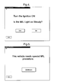
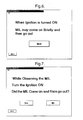
- Figures 3-4 and Figures 5-7 An alternative integration of KOEO prompts with programming criteria is illustrated in Figures 3-4 and Figures 5-7.
- Figures 3-4 demonstrate a KOEO test (in the case of an OBD II compliant vehicle), where the MIL illuminates so long as the key is turned to the KOEO position.
- Figures 5-7 demonstrate a KEOE test in the case of an OBD II non-compliant vehicle, where the MIL illuminates briefly and then goes out.
- the inspector starts from the initial test screen in Figure 1e and proceeds through the screens in Figures 2a-2l, and then conducts either the KOEO through Figures 3-4 or the KOEO through Figures 5-7.
- the analyzer 10 determines the correct sequence based on the particular vehicle being tested. In either case, a flag is set during the KOEO test sequence and the inspector proceeds to the screen shown in Figure 8 at the end of the KOEO test sequence.
- the screen in Figure 8 prompts the inspector to locate the OBD II connector. If the inspector indicates that the connector is not present, then the failure screen shown in Figure 9 is displayed and the test is finished. It is also contemplated that additional follow-up questions could be prompted, such as whether the connector has been removed. If the connector is present, however, the screen shown in Figure 10 is displayed to prompt the inspector to determine if the connector is in working order. If not, the screen in Figure 9 is displayed and the test is finished; otherwise, the screen illustrated in Figure 11 prompts the inspector to connect the analyzer 10 to the data link connector.
- the analyzer 10 is preferably equipped with a standard SAE J1978 OBD connector and communications link to allow readiness codes, fault codes, Malfunction Indicator Light (MIL) status, VIN number (when available), PID count and PCM-ID to be downloaded thereto from the on-board computer for applicable vehicles.
- MIL Malfunction Indicator Light
- VIN number when available
- PID count when available
- PCM-ID PCM-ID
- the equipment design and operation meets all Federal requirements (contained in 40 CFR 85.2207-2231) and recommended SAE practices (e.g., J1962, J1978 and J1979) for OBD II system inspections.
- OBD II interrogation process is fully integrated with the analyzer 10, no inspector intervention is required for collecting and recording the OBD data retrieved via the OBD diagnostic link.
- the OBD II readiness codes, failure codes, MIL status, VIN number (when available), PID count and PCM-ID are automatically retrieved through a standard interface and vehicle connector. Thus, no manually linked hand-held unit or separate interface is used.
- the analyzer 10 then prompts the inspector for an OBD II diagnostic link connection for all passenger vehicles and light-duty trucks whose model year is equal to or newer than the vehicle model year contained in the OBD_MODEL_YR field in QUETEST.DAT.
- the analyzer 10 is also designed to provide assistance to the inspector by providing OBD II connector locations through an OBD II connector location look-up table included within the OBD-VLT table, as stated previously.
- a Mode $01, PID $01 request (i.e., for current powertrain diagnostic data in accordance with SAE J1979 requirements) is transmitted to the on-board computer to determine the evaluation status of the OBD system, the number of emission-related trouble codes stored in memory, and the Malfunction Indicator Light (MIL) status.
- MIL Malfunction Indicator Light
- the system downloads and stores PID count and PCM-ID.
- the analyzer 10 displays the following prompt:
- the analyzer 10 may require the technician to "Try Again” one time. However, if after the second attempt no response is received from the OBD computer to the Mode $01, RID $01 request, then the following actions are taken by the system:
- the analyzer 10 determines which on-board monitors are supported by the OBD system, as well as and the readiness code status of each applicable monitors.
- the various monitors include the following:
- the possible readiness code responses include: completed, not completed, or not supported/not enabled.
- a response that a monitor is not supported or not enabled means that, for that particular vehicle, that monitor is not applicable.
- the analyzer 10 does not "fail" the vehicle for detecting such a code.
- the analyzer 10 evaluates the MIL status based on the data returned via the OBD link from the vehicle's OBD computer.
- the Yes/No (Y/N) status of whether the MIL has been commanded to be illuminated is recorded in the OBD MIL Status field of VEHICLE.DAT. If the MIL is commanded on, the analyzer 10 sends a Mode $03 request to the on-board computer to determine the number of stored OBD II related powertrain diagnostic trouble codes.
- the analyzer 10 retrieves the codes until the number of codes retrieved equals the number expected based on the initial Mode $01 response.
- the analyzer 10 also counts the number of readiness monitors applicable to the vehicle being tested that have a value of true ("T") specified in QUETEST.DAT, but that do not have the appropriate readiness codes set (i.e., a value of "0" or "1" is not returned via the OBD link from the vehicle on-board diagnostic system). If (1) the number of "not ready” monitors exceeds the NO_OBD_NOT_RDY in QUETEST.DAT for the model year being tested, or (2) if the vehicle fails the KOEO test, or (3) if the MIL is commanded on, then:
- the analyzer 10 In addition to each of the recorded OBD II parameters discussed above, the analyzer 10 also downloads and records parameter identification (PID) count and PCM Module ID during each inspection.
- PID parameter identification
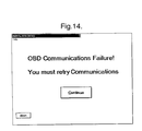
- the inspection eventually proceeds from the screen shown in Figure 11 to the final screen shown in Figure 12, assuming communication is successfully established. Text messages concerning the countdown of time and the progress of the test may also be displayed before arriving at the screen in Figure 12. At this point, the test results may then be printed out. However, if communication is not successfully established, then the inspection process proceeds from the screen displayed in Figure 11 to the screens shown in Figures 13-14, wherein the inspector attempts to test the vehicle again. If continued attempts fail, then the process proceeds to the screen in Figure 9, where the test is completed as a failure.
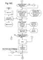
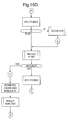
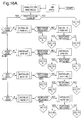
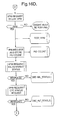
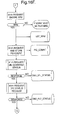
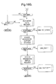
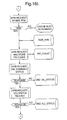
- Figures 15a-15e illustrate exemplary logic behind one possible method embodiment as the analyzer 10.
- the method first determines if the vehicle is OBD equipped, and if so proceeds through the appropriate KOEO test for the vehicle.
- the method determines if the vehicle is problematic so as to require an IM subroutine, and determines whether the connector is intact and instructs the inspector to connect the analyzer to the on-board computer. Attempts are made to establish communication (several times if necessary).
- the method further stores the Parameter Identification (PID) and the Module Identification information, analyzes the flags, and finally prints the results.
- PID Parameter Identification
Landscapes
- Chemical & Material Sciences (AREA)
- Engineering & Computer Science (AREA)
- Combustion & Propulsion (AREA)
- Physics & Mathematics (AREA)
- General Physics & Mathematics (AREA)
- Testing Of Engines (AREA)
- Management, Administration, Business Operations System, And Electronic Commerce (AREA)
- Vehicle Cleaning, Maintenance, Repair, Refitting, And Outriggers (AREA)
Abstract
Description
an 'F' is written to the OBD_FLT_R ESULT, OBD_RESULT in VEHICLE.DAT and to OVERALL_TEST_RESULT in EMISSION_RESULT.DAT if TEST DATE > OBD FAIL START DATE;
the DTC(s) found are written to OBD_FLT_CODES in VEH ICLE. DAT.
While the invention has been described with reference to a preferred embodiment(s), it will be understood by those skilled in the art that various changes may be made and equivalents may be substituted for elements thereof without departing from the scope of the invention. In addition, many modifications may be made to adapt a particular situation or material to the teachings of the invention without departing from the essential scope thereof. Therefore, it is intended that the invention not be limited to the particular embodiment disclosed as the best mode contemplated for carrying out this invention, but that the invention will include all embodiments falling within the scope of the appended claims.
Claims (19)
- A method for on-board diagnostics testing of a vehicle under inspection, the method comprising:wherein said software system manages said user interface, said communications link, and said analysis and reporting module in a manner guiding an inspector through an inspection of the vehicle; andconfiguring a user interface in communication with a software system;configuring a communications link in communication with said software system, said software system capable of communicating with an on-board vehicle computer system (100); andconfiguring an analysis and reporting module in communication with said software system;
wherein an inspection of the vehicle includes an analysis of the on-board vehicle computer system (100). - The method of claim 1, further comprising:wherein, if the vehicle under inspection is subject to on-board diagnostics testing, then said software system guides an inspector through a vehicle inspection process.receiving inputted vehicle data fields for the vehicle under inspection;comparing said inputted vehicle data fields to data contained in a vehicle lookup table; anddetermining whether the vehicle under inspection is subject to on-board diagnostics testing;
- The method of claim 2, further comprising:wherein, if it is determined that the vehicle under inspection is subject to a specialized test procedure, then said software system guides the inspector through said specialized test procedure.if said vehicle under inspection is subject to on-board diagnostic testing, then determining, based upon said inputted vehicle data fields and said data contained in said vehicle lookup table, whether the vehicle under inspection is subject to a standardized test procedure or a specialized test procedure corresponding to the vehicle under inspection;
- The method of claim 2, further comprising:wherein information on the location of said on-board diagnostic connector is also included in said vehicle lookup table.directing the inspector to locate an on-board diagnostic connector in the vehicle under inspection;
- The method of claim 4, further comprising:establishing communication between said analysis and reporting module and said on-board vehicle computer system (100);verifying the operational status of a malfunction indicator light (MIL) included within said vehicle under inspection;determining whether said MIL has been commanded on during the operation of said vehicle under inspection; andretrieving and storing vehicle diagnostic trouble codes.
- The method of claim 4, further comprising:wherein a possible readiness status for each vehicle parameter monitor includes one of: completed, not completed, and not enabled.determining a readiness status for each of a set of vehicle parameter monitors, said readiness status indicative of whether a given vehicle parameter monitor has had sufficient time to monitor the parameter associated therewith;
- The method of claim 6, wherein said set of vehicle parameter monitors includes at least one of: a misfire, a fuel system, a comprehensive component, a catalyst, a heated catalyst, an evaporative system, a secondary air system, an air conditioning system, an oxygen sensor, an oxygen sensor heater, and an exhaust gas recirculation system monitor.
- A vehicle analysis system for use with vehicles having on-board diagnostics, the system comprising:wherein said software system manages said user interface, said communications link, and said analysis and reporting module in a manner guiding an inspector through an inspection of the vehicle; anda software system;a user interface in communication with said software system;a communications link in communication with said software system for communicating with an on-board vehicle computer system (100); andan analysis and reporting module in communication with said software system;
wherein the inspection of the vehicle includes an analysis of the on-board vehicle computer system (100). - The vehicle analysis system of claim 8, wherein said analysis and reporting module employs an on-board diagnostics testing method, the method further comprising:wherein, if said vehicle under inspection is subject to on-board diagnostics testing, then said software system guides an inspector through a vehicle inspection process.receiving inputted vehicle data fields for a vehicle under inspection;comparing said inputted vehicle data fields to data contained in a vehicle lookup table; anddetermining whether said vehicle under inspection is subject to on-board diagnostics testing;
- The vehicle analysis system of claim 9, wherein the on-board diagnostics testing method further comprises:wherein, if it is determined that said vehicle under inspection is subject to a specialized test procedure, then said software system guides the inspector through said specialized test procedure.if said vehicle under inspection is subject to on-board diagnostic testing, then determining, based upon said inputted vehicle data fields and said data contained in said vehicle lookup table, whether said vehicle under inspection is subject to a standardized test procedure or a specialized test procedure corresponding to said vehicle under inspection;
- The vehicle analysis system of claim 9, wherein the on-board diagnostics testing method further comprises:wherein information on the location of said on-board diagnostic connector is also included in said vehicle lookup table.directing the inspector to locate an on-board diagnostic connector in said vehicle under inspection;
- The vehicle analysis system of claim 11, wherein the on-board diagnostics testing method further comprises:establishing communication between said analysis and reporting module and said on-board vehicle computer system (100);verifying the operational status of a malfunction indicator light (MIL) included within said vehicle under inspection;determining whether said MIL has been commanded on during the operation of said vehicle under inspection; andretrieving and storing vehicle diagnostic trouble codes.
- The vehicle analysis system of claim 11, wherein the on-board diagnostics testing method further comprises:wherein a possible readiness status for each vehicle parameter monitor includes one of: completed, not completed, and not enabled.determining a readiness status for each of a set of vehicle parameter monitors, said readiness status indicative of whether a given vehicle parameter monitor has had sufficient time to monitor the parameter associated therewith;
- The vehicle analysis system of claim 13, wherein said set of vehicle parameter monitors includes at least one of: a misfire, a fuel system, a comprehensive component, a catalyst, a heated catalyst, an evaporative system, a secondary air system, an air conditioning system, an oxygen sensor, an oxygen sensor heater, and an exhaust gas recirculation system monitor.
- The vehicle analysis system of claim 9, further comprising bar code scanning means in communication with said software system for scanning vehicle data fields for a vehicle under inspection, wherein said vehicle data fields include at least one of: a make, a model, and a model year of a registered vehicle.
- The vehicle analysis system of claim 8, further comprising a server system (102), wherein said analysis and reporting module is resident at a server location, and wherein a client (104) calls said analysis and reporting module from a client location.
- The vehicle analysis system of claim 16, wherein said client location is the same as said server location.
- The vehicle analysis system of claim 16, wherein said client location is physically networked with said server location.
- The vehicle analysis system of claim 16, wherein said client location is wirelessly networked with said server location.
Applications Claiming Priority (2)
| Application Number | Priority Date | Filing Date | Title |
|---|---|---|---|
| US10/127,248 US6529808B1 (en) | 2002-04-22 | 2002-04-22 | Method and system for analyzing an on-board vehicle computer system |
| US127248 | 2002-04-22 |
Publications (3)
| Publication Number | Publication Date |
|---|---|
| EP1356996A2 true EP1356996A2 (en) | 2003-10-29 |
| EP1356996A3 EP1356996A3 (en) | 2004-09-29 |
| EP1356996B1 EP1356996B1 (en) | 2006-06-07 |
Family
ID=22429099
Family Applications (1)
| Application Number | Title | Priority Date | Filing Date |
|---|---|---|---|
| EP03075918A Expired - Lifetime EP1356996B1 (en) | 2002-04-22 | 2003-03-31 | Method and system for on-board diagnostics testing of a vehicle |
Country Status (3)
| Country | Link |
|---|---|
| US (1) | US6529808B1 (en) |
| EP (1) | EP1356996B1 (en) |
| DE (1) | DE60305783T2 (en) |
Cited By (6)
| Publication number | Priority date | Publication date | Assignee | Title |
|---|---|---|---|---|
| EP1895377A1 (en) * | 2006-08-22 | 2008-03-05 | Scania CV AB | Fault diagnosis |
| US7529643B2 (en) | 2006-06-22 | 2009-05-05 | Scania Cv Ab | Fault diagnosis |
| US8219275B2 (en) | 2006-06-22 | 2012-07-10 | Scania Cv Ab | Fault diagnosis |
| WO2012109742A3 (en) * | 2011-02-18 | 2013-01-17 | 650340 N.B. Ltd. | Systems and methods for extraction of vehicle operational data and sharing data with authorized computer networks |
| CN108323189A (en) * | 2017-07-14 | 2018-07-24 | 深圳市元征科技股份有限公司 | Vehicular diagnostic method, terminal device and computer readable storage medium |
| CN109000876A (en) * | 2018-04-28 | 2018-12-14 | 南京航空航天大学 | SNS optical fiber based on autocoder deep learning impacts recognition methods |
Families Citing this family (109)
| Publication number | Priority date | Publication date | Assignee | Title |
|---|---|---|---|---|
| US6421791B1 (en) * | 2000-06-14 | 2002-07-16 | Delphi Technologies, Inc. | Computer-implemented system and method for evaluating the diagnostic state of a component |
| US6803236B2 (en) * | 2001-08-10 | 2004-10-12 | Delphi Technologies, Inc. | Diagnostic system for monitoring catalyst performance |
| US20150170521A1 (en) | 2001-09-11 | 2015-06-18 | Zonar Systems, Inc. | System and method to enhance the utility of vehicle inspection records by including route identification data in each vehicle inspection record |
| US8810385B2 (en) | 2001-09-11 | 2014-08-19 | Zonar Systems, Inc. | System and method to improve the efficiency of vehicle inspections by enabling remote actuation of vehicle components |
| US7557696B2 (en) * | 2001-09-11 | 2009-07-07 | Zonar Systems, Inc. | System and process to record inspection compliance data |
| US8972179B2 (en) * | 2006-06-20 | 2015-03-03 | Brett Brinton | Method and apparatus to analyze GPS data to determine if a vehicle has adhered to a predetermined route |
| US7680595B2 (en) * | 2006-06-20 | 2010-03-16 | Zonar Systems, Inc. | Method and apparatus to utilize GPS data to replace route planning software |
| US10185455B2 (en) | 2012-10-04 | 2019-01-22 | Zonar Systems, Inc. | Mobile computing device for fleet telematics |
| US20110068954A1 (en) | 2006-06-20 | 2011-03-24 | Zonar Systems, Inc. | Method and apparatus to collect object identification data during operation of a vehicle and analysis of such data |
| US8400296B2 (en) | 2001-09-11 | 2013-03-19 | Zonar Systems, Inc. | Method and apparatus to automate data collection during a mandatory inspection |
| US11341853B2 (en) | 2001-09-11 | 2022-05-24 | Zonar Systems, Inc. | System and method to enhance the utility of vehicle inspection records by including route identification data in each vehicle inspection record |
| US9563869B2 (en) | 2010-09-14 | 2017-02-07 | Zonar Systems, Inc. | Automatic incorporation of vehicle data into documents captured at a vehicle using a mobile computing device |
| US6671646B2 (en) * | 2001-09-11 | 2003-12-30 | Zonar Compliance Systems, Llc | System and process to ensure performance of mandated safety and maintenance inspections |
| JP2003098044A (en) * | 2001-09-25 | 2003-04-03 | Sanshin Ind Co Ltd | Ship inspection equipment, ship inspection system |
| DE10150631C5 (en) * | 2001-10-12 | 2014-04-10 | Jungheinrich Aktiengesellschaft | Industrial truck with interface for diagnostic data |
| US7260505B2 (en) * | 2002-06-26 | 2007-08-21 | Honeywell International, Inc. | Method and apparatus for developing fault codes for complex systems based on historical data |
| US8010423B2 (en) * | 2002-08-29 | 2011-08-30 | International Business Machines Corporation | Anticipatory mobile system service brokering and resource planning from multiple providers |
| US6847872B2 (en) * | 2002-11-07 | 2005-01-25 | International Business Machines Corporation | Supplemental diagnostic and services resource planning for mobile systems |
| US8027843B2 (en) * | 2002-11-07 | 2011-09-27 | International Business Machines Corporation | On-demand supplemental diagnostic and service resource planning for mobile systems |
| US7447642B2 (en) * | 2002-11-07 | 2008-11-04 | International Business Machines Corporation | Location based services revenue sharing and cost offsetting |
| US20040093289A1 (en) * | 2002-11-07 | 2004-05-13 | International Business Machines Corporation | Location based services anonymous session tracking and anonymous information aggregation |
| US20040093299A1 (en) * | 2002-11-07 | 2004-05-13 | International Business Machines Corporation | System and method for coalescing information for presentation to a vehicle operator |
| US6708092B1 (en) | 2002-11-11 | 2004-03-16 | Eaton Corporation | Method of grouping message identification and parameter identifications for a diagnostic system |
| US20050005167A1 (en) * | 2003-07-02 | 2005-01-06 | Kelly Thomas J. | Systems and methods for providing security operations in a work machine |
| US20050002354A1 (en) * | 2003-07-02 | 2005-01-06 | Kelly Thomas J. | Systems and methods for providing network communications between work machines |
| US7983820B2 (en) * | 2003-07-02 | 2011-07-19 | Caterpillar Inc. | Systems and methods for providing proxy control functions in a work machine |
| US7532640B2 (en) | 2003-07-02 | 2009-05-12 | Caterpillar Inc. | Systems and methods for performing protocol conversions in a machine |
| US7516244B2 (en) * | 2003-07-02 | 2009-04-07 | Caterpillar Inc. | Systems and methods for providing server operations in a work machine |
| US6947817B2 (en) * | 2003-11-03 | 2005-09-20 | Delphi Technologies, Inc. | Non-intrusive diagnostic tool for sensing oxygen sensor operation |
| US7225981B2 (en) * | 2004-01-10 | 2007-06-05 | Kenneth Jongebloed, Inc. | Adaptive network-centric online autonomic supply chain management system |
| JP4530339B2 (en) * | 2004-04-12 | 2010-08-25 | ヤマハ発動機株式会社 | Ship propulsion device shift device |
| US7012512B2 (en) * | 2004-04-14 | 2006-03-14 | St Denis Michael | OBDII readiness status notification device |
| US20060041337A1 (en) * | 2004-08-19 | 2006-02-23 | Augsburger Brett N | Web-enabled engine reprogramming |
| US20060101311A1 (en) * | 2004-10-25 | 2006-05-11 | Spx Corporation | Connectivity between a scan tool and a remote device and method |
| US8412401B2 (en) | 2004-12-30 | 2013-04-02 | Service Solutions U.S. Llc | Method and system for retrieving diagnostic information from a vehicle |
| JP4412243B2 (en) * | 2005-06-24 | 2010-02-10 | 株式会社デンソー | In-vehicle emergency call device |
| US8370016B2 (en) * | 2005-09-23 | 2013-02-05 | Spx Corporation | OBD II readiness monitor tool apparatus and method |
| US8027763B2 (en) * | 2005-09-23 | 2011-09-27 | Spx Corporation | OBD II readiness monitor tool apparatus and method |
| US9483881B2 (en) * | 2005-09-26 | 2016-11-01 | Applus Technologies Inc. | System and method for testing vehicle emissions and engine controls using a self-service on-board diagnostics kiosk |
| US7925399B2 (en) * | 2005-09-26 | 2011-04-12 | Applus Technologies, Inc. | Method and apparatus for testing vehicle emissions and engine controls using a self-service on-board diagnostics kiosk |
| JP4925701B2 (en) | 2006-03-28 | 2012-05-09 | ヤマハ発動機株式会社 | Ship |
| US7769499B2 (en) * | 2006-04-05 | 2010-08-03 | Zonar Systems Inc. | Generating a numerical ranking of driver performance based on a plurality of metrics |
| US8230362B2 (en) * | 2006-05-31 | 2012-07-24 | Manheim Investments, Inc. | Computer-assisted and/or enabled systems, methods, techniques, services and user interfaces for conducting motor vehicle and other inspections |
| US9189960B2 (en) | 2006-05-31 | 2015-11-17 | Manheim Investments, Inc. | Computer-based technology for aiding the repair of motor vehicles |
| US7953530B1 (en) * | 2006-06-08 | 2011-05-31 | Pederson Neal R | Vehicle diagnostic tool |
| US20130164715A1 (en) | 2011-12-24 | 2013-06-27 | Zonar Systems, Inc. | Using social networking to improve driver performance based on industry sharing of driver performance data |
| US10056008B1 (en) | 2006-06-20 | 2018-08-21 | Zonar Systems, Inc. | Using telematics data including position data and vehicle analytics to train drivers to improve efficiency of vehicle use |
| US9384111B2 (en) | 2011-12-23 | 2016-07-05 | Zonar Systems, Inc. | Method and apparatus for GPS based slope determination, real-time vehicle mass determination, and vehicle efficiency analysis |
| US9230437B2 (en) | 2006-06-20 | 2016-01-05 | Zonar Systems, Inc. | Method and apparatus to encode fuel use data with GPS data and to analyze such data |
| US20080016504A1 (en) * | 2006-07-14 | 2008-01-17 | Wesley Homer Cheng | Dynamically programmable electronic data collection system combining declarative programming and native coding |
| US20080016207A1 (en) * | 2006-07-14 | 2008-01-17 | Wesley Homer Cheng | Electronic driver log application with bi-directional messaging to multiple backend systems |
| US20080015748A1 (en) * | 2006-07-14 | 2008-01-17 | David Nagy | System for monitoring, controlling, and reporting vehicle operation through onboard diagnostic port |
| US20080082221A1 (en) * | 2006-07-14 | 2008-04-03 | David Nagy | System for monitoring, controlling, and reporting vehicle operation through onboard diagnostic port |
| JP4999387B2 (en) * | 2006-07-24 | 2012-08-15 | ヤマハ発動機株式会社 | Ship |
| US20080033609A1 (en) * | 2006-08-04 | 2008-02-07 | Ramin Razavi | Automotive diagnostic and tuning system |
| US7689334B2 (en) * | 2006-09-28 | 2010-03-30 | Perkins Engines Company Limited | Engine diagnostic method |
| US20080312786A1 (en) * | 2007-06-14 | 2008-12-18 | Qualcomm Incorporated | Wireless on-board diagnostics for heavy duty trucks |
| US20090265055A1 (en) * | 2008-04-17 | 2009-10-22 | Winston Lynn Gillies | System and method for performing automotive diagnostics |
| US7620484B1 (en) * | 2008-06-02 | 2009-11-17 | Chen Ieon C | Automotive mobile diagnostics |
| US20110080256A1 (en) * | 2009-10-02 | 2011-04-07 | Mehalshick Sr George M | Vehicle access system |
| KR101282417B1 (en) * | 2009-12-08 | 2013-07-04 | 한국전자통신연구원 | Apparatus and method for making CAN data file for test |
| US10665040B2 (en) | 2010-08-27 | 2020-05-26 | Zonar Systems, Inc. | Method and apparatus for remote vehicle diagnosis |
| US10600096B2 (en) | 2010-11-30 | 2020-03-24 | Zonar Systems, Inc. | System and method for obtaining competitive pricing for vehicle services |
| US12125082B2 (en) * | 2010-11-30 | 2024-10-22 | Zonar Systems, Inc. | System and method for obtaining competitive pricing for vehicle services |
| US10431020B2 (en) | 2010-12-02 | 2019-10-01 | Zonar Systems, Inc. | Method and apparatus for implementing a vehicle inspection waiver program |
| US8736419B2 (en) | 2010-12-02 | 2014-05-27 | Zonar Systems | Method and apparatus for implementing a vehicle inspection waiver program |
| US10706647B2 (en) | 2010-12-02 | 2020-07-07 | Zonar Systems, Inc. | Method and apparatus for implementing a vehicle inspection waiver program |
| US9527515B2 (en) | 2011-12-23 | 2016-12-27 | Zonar Systems, Inc. | Vehicle performance based on analysis of drive data |
| US8838362B2 (en) | 2011-02-03 | 2014-09-16 | Raytheon Company | Low-drain, self-contained monitoring device |
| US8626568B2 (en) * | 2011-06-30 | 2014-01-07 | Xrs Corporation | Fleet vehicle management systems and methods |
| DE102012202914A1 (en) * | 2012-02-27 | 2013-08-29 | Robert Bosch Gmbh | Diagnostic method and diagnostic device for a vehicle component of a vehicle |
| US20130261939A1 (en) | 2012-04-01 | 2013-10-03 | Zonar Systems, Inc. | Method and apparatus for matching vehicle ecu programming to current vehicle operating conditions |
| US9279406B2 (en) | 2012-06-22 | 2016-03-08 | Illinois Tool Works, Inc. | System and method for analyzing carbon build up in an engine |
| US9424696B2 (en) | 2012-10-04 | 2016-08-23 | Zonar Systems, Inc. | Virtual trainer for in vehicle driver coaching and to collect metrics to improve driver performance |
| US20140108155A1 (en) | 2012-10-16 | 2014-04-17 | Max L. Johnson, JR. | Communication of promotions based on data associated with a vehicle |
| KR101490936B1 (en) * | 2013-12-05 | 2015-02-06 | 현대자동차 주식회사 | Inspection system control method for vehicle |
| WO2015103159A1 (en) * | 2013-12-30 | 2015-07-09 | Tieman Craig Arnold | Connected vehicle system with infotainment interface for mobile devices |
| JP6281483B2 (en) * | 2014-04-17 | 2018-02-21 | 株式会社デンソー | Failure detection system, information processing apparatus, and vehicle mounting apparatus |
| US10656280B2 (en) | 2014-05-13 | 2020-05-19 | Key Control Holding, Inc. | Vehicle monitoring systems and methods |
| GB201420496D0 (en) | 2014-10-01 | 2014-12-31 | Continental Intelligent Transporation Systems Llc | Package delivery to and pick-up from a vehicle |
| US9483886B2 (en) | 2014-10-01 | 2016-11-01 | Continental Intelligent Transportation Systems, LLC | Method and system for remote access control |
| US9821768B2 (en) | 2014-10-01 | 2017-11-21 | Continental Intelligent Transportation Systems LLC | Geo-proximity vehicle alert and access system for security and package exchange efficiency |
| US9508204B2 (en) | 2014-10-01 | 2016-11-29 | Continental Intelligent Transportation Systems, LLC | Package exchange and service system using a key fob simulator |
| US10002479B2 (en) | 2014-10-01 | 2018-06-19 | Continental Intelligent Transportation Systems, LLC | End to end system for service delivery to and from a vehicle using a dongle |
| US10282923B2 (en) * | 2014-12-30 | 2019-05-07 | Craig A. Tieman | Connected vehicle system with infotainment interface for mobile devices |
| US9443360B1 (en) | 2015-02-27 | 2016-09-13 | TrueLite Trace, Inc. | Unknown on-board diagnostics (OBD) protocol interpreter and conversion system |
| US11144888B2 (en) * | 2015-10-02 | 2021-10-12 | Snap-On Incorporated | Method and system for augmenting real-fix tips with additional content |
| US9824512B2 (en) * | 2016-02-05 | 2017-11-21 | Ford Global Technologies, Llc | Adjusting diagnostic tests based on collected vehicle data |
| US9934624B2 (en) | 2016-08-12 | 2018-04-03 | Snap-On Incorporated | Method and system for providing diagnostic filter lists |
| US10269191B2 (en) | 2016-08-12 | 2019-04-23 | Snap-On Incorporated | Method and system for displaying PIDs based on a PID filter list |
| US10437244B2 (en) * | 2017-07-18 | 2019-10-08 | Ford Global Technologies, Llc | Remote vehicle insturction |
| US10977019B2 (en) * | 2017-11-15 | 2021-04-13 | Cub Elecparts Inc. | Vehicle radar setting method |
| US11574510B2 (en) | 2020-03-30 | 2023-02-07 | Innova Electronics Corporation | Multi-functional automotive diagnostic tablet with interchangeable function-specific cartridges |
| CN111741063A (en) * | 2020-05-13 | 2020-10-02 | 南斗六星系统集成有限公司 | A method and system for data access processing of vehicle supervision platform |
| US11932080B2 (en) | 2020-08-20 | 2024-03-19 | Denso International America, Inc. | Diagnostic and recirculation control systems and methods |
| US12269315B2 (en) | 2020-08-20 | 2025-04-08 | Denso International America, Inc. | Systems and methods for measuring and managing odor brought into rental vehicles |
| US11881093B2 (en) | 2020-08-20 | 2024-01-23 | Denso International America, Inc. | Systems and methods for identifying smoking in vehicles |
| US12017506B2 (en) | 2020-08-20 | 2024-06-25 | Denso International America, Inc. | Passenger cabin air control systems and methods |
| US12251991B2 (en) | 2020-08-20 | 2025-03-18 | Denso International America, Inc. | Humidity control for olfaction sensors |
| US12377711B2 (en) | 2020-08-20 | 2025-08-05 | Denso International America, Inc. | Vehicle feature control systems and methods based on smoking |
| US11760170B2 (en) | 2020-08-20 | 2023-09-19 | Denso International America, Inc. | Olfaction sensor preservation systems and methods |
| US11813926B2 (en) | 2020-08-20 | 2023-11-14 | Denso International America, Inc. | Binding agent and olfaction sensor |
| US11760169B2 (en) | 2020-08-20 | 2023-09-19 | Denso International America, Inc. | Particulate control systems and methods for olfaction sensors |
| US11636870B2 (en) | 2020-08-20 | 2023-04-25 | Denso International America, Inc. | Smoking cessation systems and methods |
| US11828210B2 (en) | 2020-08-20 | 2023-11-28 | Denso International America, Inc. | Diagnostic systems and methods of vehicles using olfaction |
| US11798325B2 (en) | 2020-12-09 | 2023-10-24 | Cummins Inc. | Fault isolation using on-board diagnostic (OBD) capability data |
| US12205419B2 (en) * | 2022-03-02 | 2025-01-21 | Moj.Io, Inc. | Mobile compute system with interface verification mechanism and method of operation thereof |
| CN115373883A (en) * | 2022-08-04 | 2022-11-22 | 深圳市元征软件开发有限公司 | Diagnostic interface searching method, system, electronic device and storage medium |
| US20260220983A1 (en) * | 2025-01-24 | 2026-07-30 | Ford Global Technologies, Llc | Vehicle repair system |
Family Cites Families (7)
| Publication number | Priority date | Publication date | Assignee | Title |
|---|---|---|---|---|
| US5729452A (en) | 1995-03-31 | 1998-03-17 | Envirotest Acquisition Co. | Method and system for diagnosing and reporting failure of a vehicle emission test |
| US6052631A (en) * | 1997-08-08 | 2000-04-18 | Management Systems Data Service, Inc. ("Msds, Inc.") | Method and system for facilitating vehicle inspection to detect previous damage and repairs |
| US6285931B1 (en) | 1998-02-05 | 2001-09-04 | Denso Corporation | Vehicle information communication system and method capable of communicating with external management station |
| GB2350443A (en) * | 1999-05-22 | 2000-11-29 | Luk Getriebe Systeme Gmbh | Diagnostic system, particularly for motor vehicles |
| US6430164B1 (en) * | 1999-06-17 | 2002-08-06 | Cellport Systems, Inc. | Communications involving disparate protocol network/bus and device subsystems |
| US6339736B1 (en) | 2000-03-31 | 2002-01-15 | International Business Machines Corporation | System and method for the distribution of automotive services |
| DE10039965A1 (en) * | 2000-08-16 | 2002-02-28 | Siemens Ag | Method and arrangement for exhaust gas analysis on motor vehicles with on-board engine control and diagnostic system |
-
2002
- 2002-04-22 US US10/127,248 patent/US6529808B1/en not_active Expired - Lifetime
-
2003
- 2003-03-31 EP EP03075918A patent/EP1356996B1/en not_active Expired - Lifetime
- 2003-03-31 DE DE60305783T patent/DE60305783T2/en not_active Expired - Fee Related
Cited By (9)
| Publication number | Priority date | Publication date | Assignee | Title |
|---|---|---|---|---|
| US7529643B2 (en) | 2006-06-22 | 2009-05-05 | Scania Cv Ab | Fault diagnosis |
| US8219275B2 (en) | 2006-06-22 | 2012-07-10 | Scania Cv Ab | Fault diagnosis |
| EP1895377A1 (en) * | 2006-08-22 | 2008-03-05 | Scania CV AB | Fault diagnosis |
| US7809986B2 (en) | 2006-08-22 | 2010-10-05 | Scania Cv Ab | Fault diagnosis |
| WO2012109742A3 (en) * | 2011-02-18 | 2013-01-17 | 650340 N.B. Ltd. | Systems and methods for extraction of vehicle operational data and sharing data with authorized computer networks |
| US9596287B2 (en) | 2011-02-18 | 2017-03-14 | 650340 N.B Ltd. | Systems and methods for extraction of vehicle operational data and sharing data with authorized computer networks |
| CN108323189A (en) * | 2017-07-14 | 2018-07-24 | 深圳市元征科技股份有限公司 | Vehicular diagnostic method, terminal device and computer readable storage medium |
| EP3654124A4 (en) * | 2017-07-14 | 2021-03-03 | Shenzhen Launch Tech Co., Ltd. | VEHICLE DIAGNOSIS PROCESS, TERMINAL DEVICE AND COMPUTER READABLE INFORMATION SUPPORT |
| CN109000876A (en) * | 2018-04-28 | 2018-12-14 | 南京航空航天大学 | SNS optical fiber based on autocoder deep learning impacts recognition methods |
Also Published As
| Publication number | Publication date |
|---|---|
| US6529808B1 (en) | 2003-03-04 |
| EP1356996B1 (en) | 2006-06-07 |
| DE60305783T2 (en) | 2007-05-24 |
| DE60305783D1 (en) | 2006-07-20 |
| EP1356996A3 (en) | 2004-09-29 |
Similar Documents
| Publication | Publication Date | Title |
|---|---|---|
| US6529808B1 (en) | Method and system for analyzing an on-board vehicle computer system | |
| US9483881B2 (en) | System and method for testing vehicle emissions and engine controls using a self-service on-board diagnostics kiosk | |
| US7620484B1 (en) | Automotive mobile diagnostics | |
| US6775602B2 (en) | Method and system for vehicle emissions testing through on-board diagnostics unit inspection | |
| US7012512B2 (en) | OBDII readiness status notification device | |
| US7925399B2 (en) | Method and apparatus for testing vehicle emissions and engine controls using a self-service on-board diagnostics kiosk | |
| US12579851B2 (en) | Method and diagnostic device for performing vehicle diagnostics | |
| USRE39619E1 (en) | Automotive code reader | |
| US10332319B2 (en) | Methods and systems for updating diagnostic and repair information | |
| US6928348B1 (en) | Internet-based emissions test for vehicles | |
| US7987028B2 (en) | Method and apparatus for reading and erasing diagnostic trouble codes from a vehicle | |
| US7706936B2 (en) | Method and system for adaptively modifying diagnostic vehicle information | |
| CA2727819C (en) | Diagnostic director | |
| US8041476B2 (en) | Error message details for debug available to end user | |
| EP0286648A1 (en) | System for diagnosing anomalies or breakdowns in a plurality of types of electronic control systems installed in motor vehicles. | |
| Baltusis | On board vehicle diagnostics | |
| US12112587B1 (en) | System and method for guided vehicle diagnostics | |
| CA2403417C (en) | Method and system for vehicle emissions testing through on-board diagnostics unit inspection | |
| KR102141821B1 (en) | Korea Automobile Diagnosis Integrate System | |
| EP3252719A1 (en) | Method for diagnosing faults in a vehicle, and corresponding system | |
| Goodnight et al. | Automotive Engine Performance: CDX Master Automotive Technician Series | |
| Kotzan | On-board diagnostics for emission control systems | |
| KR102632099B1 (en) | Diagnosis and inspection system of server type for electronic devices of vehicles and method for operating thereof | |
| Klyde et al. | Advanced automotive engine performance | |
| Das | Automotive Diagnosis and Fault Shooting |
Legal Events
| Date | Code | Title | Description |
|---|---|---|---|
| PUAI | Public reference made under article 153(3) epc to a published international application that has entered the european phase |
Free format text: ORIGINAL CODE: 0009012 |
|
| AK | Designated contracting states |
Kind code of ref document: A2 Designated state(s): AT BE BG CH CY CZ DE DK EE ES FI FR GB GR HU IE IT LI LU MC NL PT RO SE SI SK TR |
|
| AX | Request for extension of the european patent |
Extension state: AL LT LV MK |
|
| PUAL | Search report despatched |
Free format text: ORIGINAL CODE: 0009013 |
|
| RIC1 | Information provided on ipc code assigned before grant |
Ipc: 7H 04L 29/08 A Ipc: 7G 01M 17/00 B Ipc: 7G 07C 5/00 B Ipc: 7B 60R 16/02 B |
|
| AK | Designated contracting states |
Kind code of ref document: A3 Designated state(s): AT BE BG CH CY CZ DE DK EE ES FI FR GB GR HU IE IT LI LU MC NL PT RO SE SI SK TR |
|
| AX | Request for extension of the european patent |
Extension state: AL LT LV MK |
|
| 17P | Request for examination filed |
Effective date: 20050329 |
|
| 17Q | First examination report despatched |
Effective date: 20050425 |
|
| AKX | Designation fees paid |
Designated state(s): DE FR GB |
|
| GRAP | Despatch of communication of intention to grant a patent |
Free format text: ORIGINAL CODE: EPIDOSNIGR1 |
|
| GRAS | Grant fee paid |
Free format text: ORIGINAL CODE: EPIDOSNIGR3 |
|
| GRAA | (expected) grant |
Free format text: ORIGINAL CODE: 0009210 |
|
| AK | Designated contracting states |
Kind code of ref document: B1 Designated state(s): DE FR GB |
|
| REG | Reference to a national code |
Ref country code: GB Ref legal event code: FG4D |
|
| REF | Corresponds to: |
Ref document number: 60305783 Country of ref document: DE Date of ref document: 20060720 Kind code of ref document: P |
|
| PLBE | No opposition filed within time limit |
Free format text: ORIGINAL CODE: 0009261 |
|
| STAA | Information on the status of an ep patent application or granted ep patent |
Free format text: STATUS: NO OPPOSITION FILED WITHIN TIME LIMIT |
|
| EN | Fr: translation not filed | ||
| 26N | No opposition filed |
Effective date: 20070308 |
|
| GBPC | Gb: european patent ceased through non-payment of renewal fee |
Effective date: 20070331 |
|
| PG25 | Lapsed in a contracting state [announced via postgrant information from national office to epo] |
Ref country code: GB Free format text: LAPSE BECAUSE OF NON-PAYMENT OF DUE FEES Effective date: 20070331 Ref country code: FR Free format text: LAPSE BECAUSE OF FAILURE TO SUBMIT A TRANSLATION OF THE DESCRIPTION OR TO PAY THE FEE WITHIN THE PRESCRIBED TIME-LIMIT Effective date: 20070309 |
|
| PGFP | Annual fee paid to national office [announced via postgrant information from national office to epo] |
Ref country code: DE Payment date: 20080407 Year of fee payment: 6 |
|
| PG25 | Lapsed in a contracting state [announced via postgrant information from national office to epo] |
Ref country code: FR Free format text: LAPSE BECAUSE OF FAILURE TO SUBMIT A TRANSLATION OF THE DESCRIPTION OR TO PAY THE FEE WITHIN THE PRESCRIBED TIME-LIMIT Effective date: 20060607 |
|
| PG25 | Lapsed in a contracting state [announced via postgrant information from national office to epo] |
Ref country code: DE Free format text: LAPSE BECAUSE OF NON-PAYMENT OF DUE FEES Effective date: 20091001 |