EP1356988A1 - Apparatus for monitoring rear of vehicle - Google Patents
Apparatus for monitoring rear of vehicle Download PDFInfo
- Publication number
- EP1356988A1 EP1356988A1 EP02014107A EP02014107A EP1356988A1 EP 1356988 A1 EP1356988 A1 EP 1356988A1 EP 02014107 A EP02014107 A EP 02014107A EP 02014107 A EP02014107 A EP 02014107A EP 1356988 A1 EP1356988 A1 EP 1356988A1
- Authority
- EP
- European Patent Office
- Prior art keywords
- vehicle
- camera
- chamber
- accommodating
- monitoring
- Prior art date
- Legal status (The legal status is an assumption and is not a legal conclusion. Google has not performed a legal analysis and makes no representation as to the accuracy of the status listed.)
- Withdrawn
Links
- 238000012544 monitoring process Methods 0.000 title claims abstract description 17
- 239000004973 liquid crystal related substance Substances 0.000 claims abstract description 10
- 230000011664 signaling Effects 0.000 claims abstract description 6
- 238000005192 partition Methods 0.000 claims abstract description 4
- 238000010276 construction Methods 0.000 description 3
- 238000010586 diagram Methods 0.000 description 2
- 230000001681 protective effect Effects 0.000 description 2
- 238000012986 modification Methods 0.000 description 1
- 230000004048 modification Effects 0.000 description 1
- 239000012780 transparent material Substances 0.000 description 1
Images


Classifications
-
- B—PERFORMING OPERATIONS; TRANSPORTING
- B60—VEHICLES IN GENERAL
- B60R—VEHICLES, VEHICLE FITTINGS, OR VEHICLE PARTS, NOT OTHERWISE PROVIDED FOR
- B60R1/00—Optical viewing arrangements; Real-time viewing arrangements for drivers or passengers using optical image capturing systems, e.g. cameras or video systems specially adapted for use in or on vehicles
- B60R1/20—Real-time viewing arrangements for drivers or passengers using optical image capturing systems, e.g. cameras or video systems specially adapted for use in or on vehicles
- B60R1/22—Real-time viewing arrangements for drivers or passengers using optical image capturing systems, e.g. cameras or video systems specially adapted for use in or on vehicles for viewing an area outside the vehicle, e.g. the exterior of the vehicle
- B60R1/23—Real-time viewing arrangements for drivers or passengers using optical image capturing systems, e.g. cameras or video systems specially adapted for use in or on vehicles for viewing an area outside the vehicle, e.g. the exterior of the vehicle with a predetermined field of view
- B60R1/26—Real-time viewing arrangements for drivers or passengers using optical image capturing systems, e.g. cameras or video systems specially adapted for use in or on vehicles for viewing an area outside the vehicle, e.g. the exterior of the vehicle with a predetermined field of view to the rear of the vehicle
-
- B—PERFORMING OPERATIONS; TRANSPORTING
- B60—VEHICLES IN GENERAL
- B60R—VEHICLES, VEHICLE FITTINGS, OR VEHICLE PARTS, NOT OTHERWISE PROVIDED FOR
- B60R1/00—Optical viewing arrangements; Real-time viewing arrangements for drivers or passengers using optical image capturing systems, e.g. cameras or video systems specially adapted for use in or on vehicles
- B60R1/02—Rear-view mirror arrangements
- B60R1/08—Rear-view mirror arrangements involving special optical features, e.g. avoiding blind spots, e.g. convex mirrors; Side-by-side associations of rear-view and other mirrors
-
- B—PERFORMING OPERATIONS; TRANSPORTING
- B60—VEHICLES IN GENERAL
- B60R—VEHICLES, VEHICLE FITTINGS, OR VEHICLE PARTS, NOT OTHERWISE PROVIDED FOR
- B60R1/00—Optical viewing arrangements; Real-time viewing arrangements for drivers or passengers using optical image capturing systems, e.g. cameras or video systems specially adapted for use in or on vehicles
- B60R1/20—Real-time viewing arrangements for drivers or passengers using optical image capturing systems, e.g. cameras or video systems specially adapted for use in or on vehicles
- B60R1/22—Real-time viewing arrangements for drivers or passengers using optical image capturing systems, e.g. cameras or video systems specially adapted for use in or on vehicles for viewing an area outside the vehicle, e.g. the exterior of the vehicle
- B60R1/28—Real-time viewing arrangements for drivers or passengers using optical image capturing systems, e.g. cameras or video systems specially adapted for use in or on vehicles for viewing an area outside the vehicle, e.g. the exterior of the vehicle with an adjustable field of view
-
- B—PERFORMING OPERATIONS; TRANSPORTING
- B60—VEHICLES IN GENERAL
- B60R—VEHICLES, VEHICLE FITTINGS, OR VEHICLE PARTS, NOT OTHERWISE PROVIDED FOR
- B60R2300/00—Details of viewing arrangements using cameras and displays, specially adapted for use in a vehicle
- B60R2300/10—Details of viewing arrangements using cameras and displays, specially adapted for use in a vehicle characterised by the type of camera system used
- B60R2300/101—Details of viewing arrangements using cameras and displays, specially adapted for use in a vehicle characterised by the type of camera system used using cameras with adjustable capturing direction
-
- B—PERFORMING OPERATIONS; TRANSPORTING
- B60—VEHICLES IN GENERAL
- B60R—VEHICLES, VEHICLE FITTINGS, OR VEHICLE PARTS, NOT OTHERWISE PROVIDED FOR
- B60R2300/00—Details of viewing arrangements using cameras and displays, specially adapted for use in a vehicle
- B60R2300/80—Details of viewing arrangements using cameras and displays, specially adapted for use in a vehicle characterised by the intended use of the viewing arrangement
- B60R2300/802—Details of viewing arrangements using cameras and displays, specially adapted for use in a vehicle characterised by the intended use of the viewing arrangement for monitoring and displaying vehicle exterior blind spot views
-
- B—PERFORMING OPERATIONS; TRANSPORTING
- B60—VEHICLES IN GENERAL
- B60R—VEHICLES, VEHICLE FITTINGS, OR VEHICLE PARTS, NOT OTHERWISE PROVIDED FOR
- B60R2300/00—Details of viewing arrangements using cameras and displays, specially adapted for use in a vehicle
- B60R2300/80—Details of viewing arrangements using cameras and displays, specially adapted for use in a vehicle characterised by the intended use of the viewing arrangement
- B60R2300/8046—Details of viewing arrangements using cameras and displays, specially adapted for use in a vehicle characterised by the intended use of the viewing arrangement for replacing a rear-view mirror system
-
- B—PERFORMING OPERATIONS; TRANSPORTING
- B60—VEHICLES IN GENERAL
- B60R—VEHICLES, VEHICLE FITTINGS, OR VEHICLE PARTS, NOT OTHERWISE PROVIDED FOR
- B60R2300/00—Details of viewing arrangements using cameras and displays, specially adapted for use in a vehicle
- B60R2300/80—Details of viewing arrangements using cameras and displays, specially adapted for use in a vehicle characterised by the intended use of the viewing arrangement
- B60R2300/8066—Details of viewing arrangements using cameras and displays, specially adapted for use in a vehicle characterised by the intended use of the viewing arrangement for monitoring rearward traffic
Definitions
- the present invention relates to an apparatus for monitoring the rear of a vehicle, and more particularly, to an apparatus for monitoring the rear of a vehicle by use of a digital camera outputting an image on a liquid crystal display mounted to a dashboard in a cabin, thereby eliminating exterior rearview mirrors and thus improving space application for left and right front fenders of the vehicle.
- FIG. 1 is a perspective view of a conventional rearview mirror of a vehicle.
- a support bracket 10 is rigidly secured to the attached portion between a casing and a window frame of the front door, and the rearview mirror 12 is installed on an upper portion of the support bracket 10.
- the driver can monitor the vehicles approaching from the rear through a mirror element 14 mounted in one side of the rearview mirror, so that the driver reduces a speed of the vehicle or changes a lane.
- the mirror element 14 is provided on its inner surface with a pivot bearing (not shown), so that the driver can adjust an angle of rear vision to confirm to his or her body type or driving lanes (e.g., superhighway, a notional highway and so forth).
- driving lanes e.g., superhighway, a notional highway and so forth.
- These rearview mirrors fail to reflect vehicles located near the rear end of the vehicle, which is commonly referred to as "blind spots.” These blind spots can hide other vehicles from the view of the driver, resulting in a collision when the driver changes lanes without turning to see if other vehicles are in the adjacent lane.
- Korean Utility-Model No. 152945 assigned to the assignee of the present invention suggests cameras for a rearview mirror each mounted on the left and right front doors of the vehicle. The camera is moved to settle the blind spot, and the scene of the collision is taken and stored by the camera.
- Fig. 2 is a perspective view of a conventional rear monitoring apparatus using the camera. A camera 20 for a rearview mirror is installed to a support bracket, and an image inputted from the camera 20 is outputted on liquid crystal displays 32 and 34 each mounted on a dashboard 30 in a cabin of a vehicle.
- the present invention is directed to an apparatus for monitoring the rear of a vehicle that substantially obviates one or more problems due to limitations and disadvantages of the related art.
- the present invention provides an apparatus for monitoring a rear of a vehicle, the apparatus including a camera for taking a picture of a rear of the vehicle, a liquid crystal display for receiving and displaying the image, and a control section for controlling the camera and the liquid crystal display, the apparatus comprising an auxiliary turn indicator, mounted on left and right front fenders of the vehicle, for accommodating the camera.
- the turn indicator includes a partition dividing a chamber into one chamber for accommodating a turn signaling lamp and the other chamber for accommodating the camera.
- Fig. 1 is a perspective view of a conventional rearview mirror of a vehicle
- Fig. 2 is a perspective view of a conventional rear monitoring apparatus using a camera
- Fig. 3 is a view illustrating a vehicle employing an apparatus for monitoring the rear according to a preferred embodiment of the present invention
- Fig. 4 is a view illustrating the structure of a corner indicator accommodating a camera for monitoring the rear of a vehicle
- Fig. 5 is a plan view of a vehicle, which depicts a filed of view of a camera.
- Fig. 6 is a block diagram showing the construction of an apparatus for monitoring the rear of the vehicle in Fig. 3.
- Fig. 3 is a view illustrating a vehicle employing an apparatus for monitoring the rear according to a preferred embodiment of the present invention
- Fig. 4 is a view illustrating the structure of a turn indicator accommodating a camera for monitoring the rear of a vehicle.
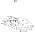
- auxiliary turn indicators 100 are mounted on left and right front fenders 140 of a vehicle.
- Liquid crystal displays 121a and 121b are installed to both side ends of a dashboard 120, so that a driver can monitor vehicles approaching from the rear of the vehicle, while seeing the front of the vehicle.
- the auxiliary turn indicator 100 includes a turn signaling lamp 200 for indicating a turn of the vehicle, a camera 300 for taking a picture of the vehicle's rear, and a protective cover 350 having a partition dividing a chamber into one chamber for accommodating the turn signaling lamp 200 and the other chamber for accommodating the camera 300.
- the camera 300 may be set and installed at an optimum angle for enabling the driver to monitor circumstances adjacent to the rear of the vehicle, or include an angle adjusting motor for adjusting an angle of the camera in all directions.
- the protective cover 350 for covering the turn signaling lamp 200 and the camera 300 is made of a transparent material so that the camera 300 can take a clear picture of the vehicle's rear.
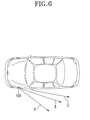
- Fig. 5 is a plan view of the vehicle, which depicts a filed of view of the camera in Fig. 3.
- a horizontal angle of view, indicated by a reference character A, of the camera 300 from the auxiliary turn indicator 100 is determined as a half of the total horizontal angle, indicated by a reference character B, of view of the camera.
- the horizontal angle of view A of the camera is within a range of 25 to 30 degrees relative to a chassis. Accordingly, the driver can see the blind spot C, which is not provided by the conventional exterior rearview mirror.
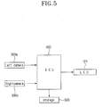
- Fig. 6 is a block diagram showing the construction of an apparatus for monitoring the rear of the vehicle in Fig. 3.
- cameras 300a and 300b are installed in auxiliary turn indicators which are mounted on left and right front fenders of a vehicle. Images taken by the cameras 300a and 300b are transmitted to a control section 400 in a digital signal.
- the control section 400 outputs the image data on a liquid crystal display 121, so that the driver can monitor the image data.
- the control section 400 may further comprise storing means 500 for storing the inputted image data.
- the present invention has some advantages of reducing an aerodynamic noise and improving a layout of the front fender of the vehicle, by eliminating the rearview mirrors.
- the blind spot can be entirely eliminated, thereby preventing a fender bender, and that when moving or parking the vehicle can be traveled on a narrow road corresponding to a width exclusive of both rearview mirrors.
Landscapes
- Engineering & Computer Science (AREA)
- Multimedia (AREA)
- Mechanical Engineering (AREA)
- Closed-Circuit Television Systems (AREA)
- Fittings On The Vehicle Exterior For Carrying Loads, And Devices For Holding Or Mounting Articles (AREA)
- Lighting Device Outwards From Vehicle And Optical Signal (AREA)
Abstract
Disclosed is an apparatus for monitoring the rear of a vehicle
capable of entirely eliminating a blind spot. The apparatus includes a
camera (200) for taking a picture of a rear of the vehicle, a liquid
crystal display for receiving and displaying the image, and a control
section for controlling the camera (300) and the liquid crystal display.
The camera (300) is installed in an auxiliary turn indicator (100)
mounted on left and right front fenders of the vehicle. The turn indicator
(100) includes a partition dividing a chamber into one chamber for
accommodating a turn signaling lamp (200) and the other chamber for accommodating
the camera (300).
Description
- The present invention relates to an apparatus for monitoring the rear of a vehicle, and more particularly, to an apparatus for monitoring the rear of a vehicle by use of a digital camera outputting an image on a liquid crystal display mounted to a dashboard in a cabin, thereby eliminating exterior rearview mirrors and thus improving space application for left and right front fenders of the vehicle.
- Generally, most automotive vehicles have rearview mirrors, called as sideview mirror, mounted on the exterior of front doors for enabling a driver to see vehicles approaching from the rear of the vehicle. Fig. 1 is a perspective view of a conventional rearview mirror of a vehicle. A
support bracket 10 is rigidly secured to the attached portion between a casing and a window frame of the front door, and therearview mirror 12 is installed on an upper portion of thesupport bracket 10. The driver can monitor the vehicles approaching from the rear through amirror element 14 mounted in one side of the rearview mirror, so that the driver reduces a speed of the vehicle or changes a lane. - The
mirror element 14 is provided on its inner surface with a pivot bearing (not shown), so that the driver can adjust an angle of rear vision to confirm to his or her body type or driving lanes (e.g., superhighway, a notional highway and so forth). These rearview mirrors fail to reflect vehicles located near the rear end of the vehicle, which is commonly referred to as "blind spots." These blind spots can hide other vehicles from the view of the driver, resulting in a collision when the driver changes lanes without turning to see if other vehicles are in the adjacent lane. - In order to address such a problem, Korean Utility-Model No. 152945 assigned to the assignee of the present invention suggests cameras for a rearview mirror each mounted on the left and right front doors of the vehicle. The camera is moved to settle the blind spot, and the scene of the collision is taken and stored by the camera. Fig. 2 is a perspective view of a conventional rear monitoring apparatus using the camera. A
camera 20 for a rearview mirror is installed to a support bracket, and an image inputted from thecamera 20 is outputted onliquid crystal displays dashboard 30 in a cabin of a vehicle. - Although it is acceptable to substitute the camera for the exterior rearview mirror, since the camera is mounted on the location of the existing exterior rearview mirror, an aerodynamic noise is generated due to the exterior camera when the vehicle travels at a high speed, as well as providing the blind spot as usual.
- Accordingly, the present invention is directed to an apparatus for monitoring the rear of a vehicle that substantially obviates one or more problems due to limitations and disadvantages of the related art.
- It is an object of the present invention to provide an apparatus for monitoring the rear of a vehicle capable of entirely eliminating a blind spot.
- It is another object of the present invention to provide an apparatus for monitoring the rear of a vehicle, in which rearview mirrors are eliminated to reduce an aerodynamic noise and improve a layout of left and right front side of the vehicle.
- In order to accomplish the above objects, the present invention provides an apparatus for monitoring a rear of a vehicle, the apparatus including a camera for taking a picture of a rear of the vehicle, a liquid crystal display for receiving and displaying the image, and a control section for controlling the camera and the liquid crystal display, the apparatus comprising an auxiliary turn indicator, mounted on left and right front fenders of the vehicle, for accommodating the camera.
- The turn indicator includes a partition dividing a chamber into one chamber for accommodating a turn signaling lamp and the other chamber for accommodating the camera.
- It is to be understood that both the foregoing general description and the following detailed description of the present invention are exemplary and explanatory and are intended to provide further explanation of the present invention as claimed.
- The accompanying drawings, which are included to provide a further understanding of the present invention and are incorporated in and constitute a part of this application, illustrate embodiment(s) of the present invention and together with the description serve to explain the principle of the present invention. In the drawings:
- Fig. 1 is a perspective view of a conventional rearview mirror of a vehicle;
- Fig. 2 is a perspective view of a conventional rear monitoring apparatus using a camera;
- Fig. 3 is a view illustrating a vehicle employing an apparatus for monitoring the rear according to a preferred embodiment of the present invention;
- Fig. 4 is a view illustrating the structure of a corner indicator accommodating a camera for monitoring the rear of a vehicle;
- Fig. 5 is a plan view of a vehicle, which depicts a filed of view of a camera; and
- Fig. 6 is a block diagram showing the construction of an apparatus for monitoring the rear of the vehicle in Fig. 3.
- Reference will now be made in detail to a preferred embodiment of the present invention.
- Fig. 3 is a view illustrating a vehicle employing an apparatus for monitoring the rear according to a preferred embodiment of the present invention, and Fig. 4 is a view illustrating the structure of a turn indicator accommodating a camera for monitoring the rear of a vehicle.
- Referring to Figs 3 and 4,
auxiliary turn indicators 100 are mounted on left and rightfront fenders 140 of a vehicle. Liquid crystal displays 121a and 121b are installed to both side ends of adashboard 120, so that a driver can monitor vehicles approaching from the rear of the vehicle, while seeing the front of the vehicle. - The
auxiliary turn indicator 100 includes aturn signaling lamp 200 for indicating a turn of the vehicle, acamera 300 for taking a picture of the vehicle's rear, and aprotective cover 350 having a partition dividing a chamber into one chamber for accommodating theturn signaling lamp 200 and the other chamber for accommodating thecamera 300. Thecamera 300 may be set and installed at an optimum angle for enabling the driver to monitor circumstances adjacent to the rear of the vehicle, or include an angle adjusting motor for adjusting an angle of the camera in all directions. Theprotective cover 350 for covering theturn signaling lamp 200 and thecamera 300 is made of a transparent material so that thecamera 300 can take a clear picture of the vehicle's rear. - Fig. 5 is a plan view of the vehicle, which depicts a filed of view of the camera in Fig. 3. A horizontal angle of view, indicated by a reference character A, of the
camera 300 from theauxiliary turn indicator 100 is determined as a half of the total horizontal angle, indicated by a reference character B, of view of the camera. Preferably, the horizontal angle of view A of the camera is within a range of 25 to 30 degrees relative to a chassis. Accordingly, the driver can see the blind spot C, which is not provided by the conventional exterior rearview mirror. - Fig. 6 is a block diagram showing the construction of an apparatus for monitoring the rear of the vehicle in Fig. 3.
- Referring to Fig. 6,
cameras cameras control section 400 in a digital signal. Thecontrol section 400 outputs the image data on aliquid crystal display 121, so that the driver can monitor the image data. Thecontrol section 400 may further comprise storing means 500 for storing the inputted image data. - With the construction described above, the present invention has some advantages of reducing an aerodynamic noise and improving a layout of the front fender of the vehicle, by eliminating the rearview mirrors.
- In addition, there are provided other advantages in that the blind spot can be entirely eliminated, thereby preventing a fender bender, and that when moving or parking the vehicle can be traveled on a narrow road corresponding to a width exclusive of both rearview mirrors.
- The forgoing embodiment is merely exemplary and is not to be construed as limiting the present invention. The present teachings can be readily applied to other types of apparatuses. The description of the present invention is intended to be illustrative, and not to limit the scope of the claims. Many alternatives, modifications, and variations will be apparent to those skilled in the art.
Claims (2)
- An apparatus for monitoring a rear of a vehicle, the apparatus including a camera for taking a picture of a rear of the vehicle, a liquid crystal display for receiving and displaying the image, and a control section for controlling the camera and the liquid crystal display, the apparatus comprising:an auxiliary turn indicator, mounted on left and right front fenders of the vehicle, for accommodating the camera.
- The apparatus as claimed in claim 1, wherein the turn indicator includes a partition dividing a chamber into one chamber for accommodating a turn signaling lamp and the other chamber for accommodating the camera.
Applications Claiming Priority (2)
| Application Number | Priority Date | Filing Date | Title |
|---|---|---|---|
| KR2002021334 | 2002-04-18 | ||
| KR10-2002-0021334A KR100475960B1 (en) | 2002-04-18 | 2002-04-18 | Apparatus for Recognizing the Rear of Vehicle |
Publications (1)
| Publication Number | Publication Date |
|---|---|
| EP1356988A1 true EP1356988A1 (en) | 2003-10-29 |
Family
ID=28786967
Family Applications (1)
| Application Number | Title | Priority Date | Filing Date |
|---|---|---|---|
| EP02014107A Withdrawn EP1356988A1 (en) | 2002-04-18 | 2002-06-24 | Apparatus for monitoring rear of vehicle |
Country Status (4)
| Country | Link |
|---|---|
| US (1) | US20030202096A1 (en) |
| EP (1) | EP1356988A1 (en) |
| JP (1) | JP2003312359A (en) |
| KR (1) | KR100475960B1 (en) |
Cited By (2)
| Publication number | Priority date | Publication date | Assignee | Title |
|---|---|---|---|---|
| FR2882310A1 (en) * | 2005-02-24 | 2006-08-25 | Fico Mirrors | Vehicle e.g. passenger car, blind spot detection device, has casing that comprises sensor and is integrated to front fender, where casing has small diameter part comprising dead angle detection opening which opens out in cavity |
| FR2921604A1 (en) * | 2007-09-28 | 2009-04-03 | Renault Sas | DEVICE FOR AIDING THE OCCULTED CHANNEL OUTPUT |
Families Citing this family (72)
| Publication number | Priority date | Publication date | Assignee | Title |
|---|---|---|---|---|
| US5910854A (en) | 1993-02-26 | 1999-06-08 | Donnelly Corporation | Electrochromic polymeric solid films, manufacturing electrochromic devices using such solid films, and processes for making such solid films and devices |
| US5668663A (en) | 1994-05-05 | 1997-09-16 | Donnelly Corporation | Electrochromic mirrors and devices |
| US6891563B2 (en) | 1996-05-22 | 2005-05-10 | Donnelly Corporation | Vehicular vision system |
| US6172613B1 (en) | 1998-02-18 | 2001-01-09 | Donnelly Corporation | Rearview mirror assembly incorporating vehicle information display |
| US8294975B2 (en) | 1997-08-25 | 2012-10-23 | Donnelly Corporation | Automotive rearview mirror assembly |
| US6326613B1 (en) | 1998-01-07 | 2001-12-04 | Donnelly Corporation | Vehicle interior mirror assembly adapted for containing a rain sensor |
| US6124886A (en) | 1997-08-25 | 2000-09-26 | Donnelly Corporation | Modular rearview mirror assembly |
| US8288711B2 (en) | 1998-01-07 | 2012-10-16 | Donnelly Corporation | Interior rearview mirror system with forwardly-viewing camera and a control |
| US6445287B1 (en) | 2000-02-28 | 2002-09-03 | Donnelly Corporation | Tire inflation assistance monitoring system |
| US6690268B2 (en) | 2000-03-02 | 2004-02-10 | Donnelly Corporation | Video mirror systems incorporating an accessory module |
| US6693517B2 (en) | 2000-04-21 | 2004-02-17 | Donnelly Corporation | Vehicle mirror assembly communicating wirelessly with vehicle accessories and occupants |
| US6477464B2 (en) | 2000-03-09 | 2002-11-05 | Donnelly Corporation | Complete mirror-based global-positioning system (GPS) navigation solution |
| US6329925B1 (en) | 1999-11-24 | 2001-12-11 | Donnelly Corporation | Rearview mirror assembly with added feature modular display |
| US7370983B2 (en) | 2000-03-02 | 2008-05-13 | Donnelly Corporation | Interior mirror assembly with display |
| US7167796B2 (en) | 2000-03-09 | 2007-01-23 | Donnelly Corporation | Vehicle navigation system for use with a telematics system |
| EP1363810B1 (en) | 2001-01-23 | 2007-05-30 | Donnelly Corporation | Improved vehicular lighting system |
| US7255451B2 (en) | 2002-09-20 | 2007-08-14 | Donnelly Corporation | Electro-optic mirror cell |
| US7581859B2 (en) | 2005-09-14 | 2009-09-01 | Donnelly Corp. | Display device for exterior rearview mirror |
| US6918674B2 (en) | 2002-05-03 | 2005-07-19 | Donnelly Corporation | Vehicle rearview mirror system |
| WO2003105099A1 (en) | 2002-06-06 | 2003-12-18 | Donnelly Corporation | Interior rearview mirror system with compass |
| US7329013B2 (en) | 2002-06-06 | 2008-02-12 | Donnelly Corporation | Interior rearview mirror system with compass |
| US7310177B2 (en) | 2002-09-20 | 2007-12-18 | Donnelly Corporation | Electro-optic reflective element assembly |
| AU2003278863A1 (en) | 2002-09-20 | 2004-04-08 | Donnelly Corporation | Mirror reflective element assembly |
| US7353086B2 (en) * | 2002-11-19 | 2008-04-01 | Timothy James Ennis | Methods and systems for providing a rearward field of view for use with motorcycles |
| US7289037B2 (en) | 2003-05-19 | 2007-10-30 | Donnelly Corporation | Mirror assembly for vehicle |
| US7446924B2 (en) | 2003-10-02 | 2008-11-04 | Donnelly Corporation | Mirror reflective element assembly including electronic component |
| US7308341B2 (en) | 2003-10-14 | 2007-12-11 | Donnelly Corporation | Vehicle communication system |
| ATE517368T1 (en) | 2005-05-16 | 2011-08-15 | Donnelly Corp | VEHICLE MIRROR ARRANGEMENT WITH CHARACTER ON THE REFLECTIVE PART |
| US20060290782A1 (en) * | 2005-06-23 | 2006-12-28 | Jung-Ting Chen | Automobile rearview imaging system |
| EP1949666B1 (en) | 2005-11-01 | 2013-07-17 | Magna Mirrors of America, Inc. | Interior rearview mirror with display |
| KR100807812B1 (en) * | 2006-03-07 | 2008-02-26 | 이스턴 마스텍 주식회사 | Vehicle side camera integrated direction indicator |
| EP1991905B1 (en) | 2006-03-09 | 2011-05-11 | Gentex Corporation | Vehicle rearview assembly including a high intensity display |
| JP4286294B2 (en) * | 2007-02-21 | 2009-06-24 | 三洋電機株式会社 | Driving support system |
| US8154418B2 (en) | 2008-03-31 | 2012-04-10 | Magna Mirrors Of America, Inc. | Interior rearview mirror system |
| US9487144B2 (en) | 2008-10-16 | 2016-11-08 | Magna Mirrors Of America, Inc. | Interior mirror assembly with display |
| FR2947780B1 (en) * | 2009-07-10 | 2011-06-10 | Peugeot Citroen Automobiles Sa | RETROVISION DEVICE FOR A MOTOR VEHICLE AND VEHICLE EQUIPPED WITH SUCH A RETROVISION DEVICE |
| KR100979881B1 (en) * | 2010-02-25 | 2010-09-02 | 남세인 | Operating device for side camera and flank indicator lamp of car |
| US20140139669A1 (en) * | 2012-01-30 | 2014-05-22 | Steven Petrillo | System and method for providing front-oriented visual information to vehicle driver |
| US8879139B2 (en) | 2012-04-24 | 2014-11-04 | Gentex Corporation | Display mirror assembly |
| US9598018B2 (en) | 2013-03-15 | 2017-03-21 | Gentex Corporation | Display mirror assembly |
| AU2014326772B2 (en) | 2013-09-24 | 2017-07-20 | Gentex Corporation | Display mirror assembly |
| US9511715B2 (en) | 2014-01-31 | 2016-12-06 | Gentex Corporation | Backlighting assembly for display for reducing cross-hatching |
| US10705332B2 (en) | 2014-03-21 | 2020-07-07 | Gentex Corporation | Tri-modal display mirror assembly |
| US9834146B2 (en) | 2014-04-01 | 2017-12-05 | Gentex Corporation | Automatic display mirror assembly |
| JP2015205618A (en) * | 2014-04-22 | 2015-11-19 | 株式会社ビートソニック | Mounting method of on-vehicle side camera and on-vehicle side camera |
| JP2016048839A (en) | 2014-08-27 | 2016-04-07 | 株式会社小糸製作所 | Electronic control unit and vehicle video system |
| US9694751B2 (en) | 2014-09-19 | 2017-07-04 | Gentex Corporation | Rearview assembly |
| WO2016073848A1 (en) | 2014-11-07 | 2016-05-12 | Gentex Corporation | Full display mirror actuator |
| KR101977685B1 (en) | 2014-11-13 | 2019-05-13 | 젠텍스 코포레이션 | Rearview mirror system with a display |
| KR101997815B1 (en) | 2014-12-03 | 2019-07-08 | 젠텍스 코포레이션 | Display mirror assembly |
| USD746744S1 (en) | 2014-12-05 | 2016-01-05 | Gentex Corporation | Rearview device |
| US9744907B2 (en) | 2014-12-29 | 2017-08-29 | Gentex Corporation | Vehicle vision system having adjustable displayed field of view |
| JP6502100B2 (en) | 2015-01-16 | 2019-04-17 | 株式会社小糸製作所 | Turn signal lamp |
| US9720278B2 (en) | 2015-01-22 | 2017-08-01 | Gentex Corporation | Low cost optical film stack |
| JP2018513810A (en) | 2015-04-20 | 2018-05-31 | ジェンテックス コーポレイション | Rear view assembly with decoration |
| WO2016187215A1 (en) | 2015-05-18 | 2016-11-24 | Gentex Corporation | Full display rearview device |
| KR102135427B1 (en) | 2015-06-22 | 2020-07-17 | 젠텍스 코포레이션 | Systems and methods for processing streamed video images to correct flicker of amplitude-modulated light |
| USD797627S1 (en) | 2015-10-30 | 2017-09-19 | Gentex Corporation | Rearview mirror device |
| US9994156B2 (en) | 2015-10-30 | 2018-06-12 | Gentex Corporation | Rearview device |
| WO2017075420A1 (en) | 2015-10-30 | 2017-05-04 | Gentex Corporation | Toggle paddle |
| USD798207S1 (en) | 2015-10-30 | 2017-09-26 | Gentex Corporation | Rearview mirror assembly |
| USD800618S1 (en) | 2015-11-02 | 2017-10-24 | Gentex Corporation | Toggle paddle for a rear view device |
| USD845851S1 (en) | 2016-03-31 | 2019-04-16 | Gentex Corporation | Rearview device |
| USD817238S1 (en) | 2016-04-29 | 2018-05-08 | Gentex Corporation | Rearview device |
| US10025138B2 (en) | 2016-06-06 | 2018-07-17 | Gentex Corporation | Illuminating display with light gathering structure |
| USD809984S1 (en) | 2016-12-07 | 2018-02-13 | Gentex Corporation | Rearview assembly |
| USD854473S1 (en) | 2016-12-16 | 2019-07-23 | Gentex Corporation | Rearview assembly |
| US20180191966A1 (en) | 2016-12-30 | 2018-07-05 | Gentex Corporation | Full display mirror with on-demand spotter view |
| US10735638B2 (en) | 2017-03-17 | 2020-08-04 | Gentex Corporation | Dual display reverse camera system |
| EP3677477A4 (en) | 2017-08-30 | 2022-11-23 | Koito Manufacturing Co., Ltd. | VEHICLE CLEANING UNIT AND SIDE INDICATOR LAMP WITH CAMERA |
| JP7022213B2 (en) * | 2018-06-27 | 2022-02-17 | 本田技研工業株式会社 | Peripheral information acquisition device and vehicle |
| EP4388243A4 (en) | 2021-08-20 | 2024-12-04 | Gentex Corporation | Lighting assembly and illumination system having a lighting assembly |
Citations (3)
| Publication number | Priority date | Publication date | Assignee | Title |
|---|---|---|---|---|
| US5289321A (en) * | 1993-02-12 | 1994-02-22 | Secor James O | Consolidated rear view camera and display system for motor vehicle |
| EP0711681A1 (en) * | 1994-06-03 | 1996-05-15 | Idesa Accesorios, S.A. | Back-vision system for vehicles |
| DE10010434A1 (en) * | 2000-03-03 | 2001-09-13 | Bosch Gmbh Robert | Camera and brake warning light integrated unit has camera mounted on third brake warning light in rear windscreen and higher than two other brake warning lights |
Family Cites Families (8)
| Publication number | Priority date | Publication date | Assignee | Title |
|---|---|---|---|---|
| JPS61166745A (en) * | 1985-01-21 | 1986-07-28 | Yamazaki Jutaku Kanri:Kk | Flasher lamp of automobile |
| US5574443A (en) * | 1994-06-22 | 1996-11-12 | Hsieh; Chi-Sheng | Vehicle monitoring apparatus with broadly and reliably rearward viewing |
| US6550949B1 (en) * | 1996-06-13 | 2003-04-22 | Gentex Corporation | Systems and components for enhancing rear vision from a vehicle |
| KR19980074048A (en) * | 1997-03-21 | 1998-11-05 | 임경춘 | Left and right side and rear state monitoring device and method in automobile |
| US6175300B1 (en) * | 1998-09-03 | 2001-01-16 | Byron K. Kendrick | Blind spot viewing system |
| JP3298851B2 (en) * | 1999-08-18 | 2002-07-08 | 松下電器産業株式会社 | Multi-function vehicle camera system and image display method of multi-function vehicle camera |
| US6642840B2 (en) * | 2000-07-28 | 2003-11-04 | Lang-Mekra North Amicica, Llc | Rearview mirror assembly with monitor |
| US20030214584A1 (en) * | 2002-05-14 | 2003-11-20 | Ross Bruce Eliot | Side and rear vision enhancement for vehicles |
-
2002
- 2002-04-18 KR KR10-2002-0021334A patent/KR100475960B1/en not_active Expired - Fee Related
- 2002-06-12 JP JP2002172020A patent/JP2003312359A/en active Pending
- 2002-06-24 EP EP02014107A patent/EP1356988A1/en not_active Withdrawn
- 2002-07-09 US US10/192,531 patent/US20030202096A1/en not_active Abandoned
Patent Citations (3)
| Publication number | Priority date | Publication date | Assignee | Title |
|---|---|---|---|---|
| US5289321A (en) * | 1993-02-12 | 1994-02-22 | Secor James O | Consolidated rear view camera and display system for motor vehicle |
| EP0711681A1 (en) * | 1994-06-03 | 1996-05-15 | Idesa Accesorios, S.A. | Back-vision system for vehicles |
| DE10010434A1 (en) * | 2000-03-03 | 2001-09-13 | Bosch Gmbh Robert | Camera and brake warning light integrated unit has camera mounted on third brake warning light in rear windscreen and higher than two other brake warning lights |
Cited By (3)
| Publication number | Priority date | Publication date | Assignee | Title |
|---|---|---|---|---|
| FR2882310A1 (en) * | 2005-02-24 | 2006-08-25 | Fico Mirrors | Vehicle e.g. passenger car, blind spot detection device, has casing that comprises sensor and is integrated to front fender, where casing has small diameter part comprising dead angle detection opening which opens out in cavity |
| FR2921604A1 (en) * | 2007-09-28 | 2009-04-03 | Renault Sas | DEVICE FOR AIDING THE OCCULTED CHANNEL OUTPUT |
| WO2009050399A1 (en) * | 2007-09-28 | 2009-04-23 | Renault S.A.S | Assistance device for exiting a blocked lane |
Also Published As
| Publication number | Publication date |
|---|---|
| JP2003312359A (en) | 2003-11-06 |
| KR20030082837A (en) | 2003-10-23 |
| KR100475960B1 (en) | 2005-03-10 |
| US20030202096A1 (en) | 2003-10-30 |
Similar Documents
| Publication | Publication Date | Title |
|---|---|---|
| US20030202096A1 (en) | Apparatus for monitoring rear of vehicle | |
| CN108340836B (en) | Automobile A column display system | |
| US7520616B2 (en) | Vehicular visual assistance system | |
| US20020113873A1 (en) | Rear vision system for large vehicles | |
| US5289321A (en) | Consolidated rear view camera and display system for motor vehicle | |
| CN100412610C (en) | Device and system for information display and vehicle equipped with such a system | |
| EP0825064A1 (en) | Apparatus for checking blind spots of vehicle | |
| JP2002225629A (en) | Vehicle monitoring device | |
| CN102219001A (en) | Exterior mirror simulation device and method | |
| CN111655541B (en) | Driver assistance systems for industrial vehicles | |
| CN1672417A (en) | observation system | |
| US20090066836A1 (en) | Front-viewing side mirror camera | |
| US7057500B1 (en) | Rear view monitoring system for motor vehicles | |
| JP2005534246A5 (en) | ||
| EP4361999B1 (en) | Camera monitor system with angled awareness lines | |
| JPH04368241A (en) | Indirect sight checking system for vehicle | |
| US20230111473A1 (en) | Support for a camera display of a vehicle | |
| JPH10194044A (en) | Rear-view check device for vehicle | |
| WO2017195693A1 (en) | Image display device | |
| US20110051269A1 (en) | True safe mirrors | |
| US20090027179A1 (en) | Auxiliary Device for Handling a Vehicle | |
| CN112406709A (en) | A vehicle monitoring device and vehicle | |
| JPH0424132A (en) | Automobile rear-view device | |
| US20260084620A1 (en) | Camera monitor system with projection displays | |
| RU2302350C2 (en) | Front view device for automobiles with steering wheel at right side |
Legal Events
| Date | Code | Title | Description |
|---|---|---|---|
| PUAI | Public reference made under article 153(3) epc to a published international application that has entered the european phase |
Free format text: ORIGINAL CODE: 0009012 |
|
| AK | Designated contracting states |
Kind code of ref document: A1 Designated state(s): AT BE CH CY DE DK ES FI FR GB GR IE IT LI LU MC NL PT SE TR |
|
| AX | Request for extension of the european patent |
Extension state: AL LT LV MK RO SI |
|
| AKX | Designation fees paid | ||
| REG | Reference to a national code |
Ref country code: DE Ref legal event code: 8566 |
|
| STAA | Information on the status of an ep patent application or granted ep patent |
Free format text: STATUS: THE APPLICATION IS DEEMED TO BE WITHDRAWN |
|
| 18D | Application deemed to be withdrawn |
Effective date: 20040430 |