EP1356976A2 - Driving force distribution method and apparatus - Google Patents
Driving force distribution method and apparatus Download PDFInfo
- Publication number
- EP1356976A2 EP1356976A2 EP03009233A EP03009233A EP1356976A2 EP 1356976 A2 EP1356976 A2 EP 1356976A2 EP 03009233 A EP03009233 A EP 03009233A EP 03009233 A EP03009233 A EP 03009233A EP 1356976 A2 EP1356976 A2 EP 1356976A2
- Authority
- EP
- European Patent Office
- Prior art keywords
- wheels
- torque
- torque command
- throttle
- driving force
- Prior art date
- Legal status (The legal status is an assumption and is not a legal conclusion. Google has not performed a legal analysis and makes no representation as to the accuracy of the status listed.)
- Granted
Links
Images


Classifications
-
- B—PERFORMING OPERATIONS; TRANSPORTING
- B60—VEHICLES IN GENERAL
- B60K—ARRANGEMENT OR MOUNTING OF PROPULSION UNITS OR OF TRANSMISSIONS IN VEHICLES; ARRANGEMENT OR MOUNTING OF PLURAL DIVERSE PRIME-MOVERS IN VEHICLES; AUXILIARY DRIVES FOR VEHICLES; INSTRUMENTATION OR DASHBOARDS FOR VEHICLES; ARRANGEMENTS IN CONNECTION WITH COOLING, AIR INTAKE, GAS EXHAUST OR FUEL SUPPLY OF PROPULSION UNITS IN VEHICLES
- B60K23/00—Arrangement or mounting of control devices for vehicle transmissions, or parts thereof, not otherwise provided for
- B60K23/08—Arrangement or mounting of control devices for vehicle transmissions, or parts thereof, not otherwise provided for for changing number of driven wheels, for switching from driving one axle to driving two or more axles
- B60K23/0808—Arrangement or mounting of control devices for vehicle transmissions, or parts thereof, not otherwise provided for for changing number of driven wheels, for switching from driving one axle to driving two or more axles for varying torque distribution between driven axles, e.g. by transfer clutch
Definitions
- This invention relates to a driving force distribution method and a driving force distribution apparatus for four-wheel-drive vehicle that has a torque transmission device.
- a driving force distribution method for a four-wheel-drive vehicle is provided as a first aspect of the present invention.
- the four-wheel-drive vehicle has a torque transmission device configured to distribute torque transmitted from an engine to a first set of wheels to a second set of wheels. Throttle-opening of the engine is detected. A first torque command which depends on the throttle-opening is obtained. A rotational speed difference between the first set of wheels and the second set of wheels is detected. A second torque command which depends on the rotational speed difference is obtained.
- the torque transmission device is controlled based on the first torque command and the second torque command so as to transmit the driving force to the second set of wheels according to the throttle-opening and the rotational speed difference. Then, a signal that corresponds to the throttle-opening is monitored. When the signal is judged being abnormal, the first torque command is ignored so that the torque transmission device is controlled based on the second torque command.
- a driving force distribution apparatus is provided as a second aspect of the present invention.
- the driving force distribution apparatus for a four-wheel-drive vehicle has a torque transmission device configured to distribute torque transmitted from an engine to a first set of wheels to a second set of wheels.
- the apparatus comprises a throttle sensor, plural speed sensors and an electrical control unit.
- the throttle sensor detects throttle-opening of the engine.
- the speed sensors detect rotational speed of the first set of wheels and the second set of wheels.
- the electrical control unit determines a first torque command which depends on the throttle-opening detected by the throttle sensor and a second torque command which depends on a rotational speed difference between the first set of wheels and the second set of wheels detected by the each speed sensor.
- the electrical control unit controls the torque transmission device based on the first torque command and the second torque command so as to transmit the driving force to the second set of wheels according to the throttle-opening and the rotational speed difference. Then, the electrical control unit monitors a signal which is detected by the throttle sensor, and when the signal judged being abnormal the first torque command is ignored so that the torque transmission device is controlled based on the second torque command.
- FIG. 1 is an explanatory view showing a main configuration of a power train of a four-wheel-drive vehicle according to the first embodiment.
- a transaxle 11 adjacently to an engine 10, into which a transmission, a transfer and a front differential 12 are assembled uniformly.
- a driving force generated by the engine 10 is transmitted to a pair of front driven shafts 13 from the transmission of the transaxle 11 through the front differential, to drive a pair of front wheels 14. Namely, the driving force is directly transmitted to the front wheels 14, so that the front wheels 14 are always driven thereby.
- a front end of a front side propeller shaft 20 is connected with the transmission by the transfer of the transaxle 11 through its gear.
- rear end of the front side propeller shaft 20 is fixed with an input portion 31 (refer to Fig. 2) of a torque transmission device 30 which is disposed at an intermediate position of the vehicle. Therefore, the input portion 31 of the torque transmission device 30 is always rotated together with the front wheels 14.
- a rear side propeller shaft 21 On an expansion line of the front propeller shaft 20, there is disposed a rear side propeller shaft 21 so that the torque transmission device 30 is sandwiched between the both propeller shafts 20 and 21.
- a front end of the rear propeller shaft 21 is fixed with an output portion 32 (refer to Fig. 2).
- the other rear end of the rear propeller shaft 21 is connected with a rear differential 17.
- rear wheels are attached onto end portions of rear driven shafts 16 which are provided with the rear differential 17 so as to extend therefrom in left and right directions, respectively. With this configuration, the rear wheels 15 are not always driven by the driving force of the engine 10, but are selectively driven according to operation of the torque transmission device 30.
- front wheels 14 correspond to "a first set of wheels"
- rear wheels correspond to "a second set of wheels” in the claim descriptions.
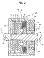
- Fig. 2 shows a basic construction of the torque transmission device 30.
- the input portion 31 of the torque transmission device 30 provides an outer case 33 consisting of a bottom wall 33T and a shaft portion 33J.
- the bottom wall 33T is arranged at the front side, while its opening is provided at the rear side.
- the front propeller shaft 20 is connected with the shaft portion 33J (refer to Fig. 1).
- a rear cover 35 is screwedly fitted into the outer case 33 so as to close the opening of the outer case 33.
- An inner shaft 34 that consists of the output 32 of the torque transmission device is liquid-tightly protruded into a through hole 35A formed in the center of the rear cover 35.
- the inner shaft 34 is rotatably supported by the outer case 33 and, is however restricted to move in an axial direction of the inner shaft 34 relative to the outer case 33.
- One end of the inner shaft 34 extends by the vicinity of the bottom wall 33T of the outer case 33, and the other end of the inner shaft 34 is connected with the rear propeller shaft 21 so as to protrudes from the outside of the torque transmission device 30 (refer to Fig. 1).
- a first cam disk 36 is rotatably supported with the inner shaft 34 at a portion close to the rear cover 35 in the outer case 33.
- Plural ring-shaped inner pilot clutch plates 37 are spline-engaged with a circumferential surface of the first cam disk 36. That is, the inner pilot clutch plates 37 are movable in the axial direction, but is restricted to rotate relative to the first cam disk 36 in a rotational direction.
- Plural outer pilot clutch plates 38 that are ring-shaped are engaged with the inner surface of the outer case 33 by splines at a portion close to rear cover 35. Therefore, the outer pilot clutch plates 38 are movable in the axial direction, but are restricted to rotate relative to the outer case 33 in the rotational direction.
- the inner pilot clutch plates 37 and the outer pilot clutch plates 38 are opposingly disposed from each other alternately of the axial direction.
- a ring-shaped armature 49 is spline-engaged with the inner surface of the outer case 33 at a position where the rear cover 35 binds the inner pilot clutch plates 37 and the outer pilot clutch plates 38 therewith.
- an electromagnetic coil 39 is disposed at a rear side of the rear cover 35.
- the electromagnetic coil 39 is accommodated into an annular groove formed on the front surface of a yoke 39A which is rotatably supported with the rear cover by a bearing (not shown).
- the inner pilot clutch plates 37 can rotate relatively to the outer pilot clutch plates 38 (referred to as "separated operation").
- the armature 49 is attracted toward the rear cover 35 with excitation of the electromagnetic coil 38, the inner pilot clutch plates 37 and the outer pilot clutch plates 38 are attracted to the rear cover 35 together with the armature 49.
- the inner pilot clutch plates 37 are frictionally engaged with the outer pilot clutch plates 38, respectively (referred to as “frictional engage operation”).
- the electromagnetic coil 39 is further excited, are further attracted to the outer pilot clutch plates 38.
- the inner pilot clutch plates 37 are completely coupled to the outer pilot clutch plates 38 with the furthest excitation of the electromagnetic coil 39 (referred to as “directly coupled operation”).
- the first cam disk 36 is rotated by torque which is transmitted from the outer case 33 through the frictional engagement or the complete coupling between the inner pilot clutch plates 37 and the outer pilot clutch plates 38.
- the above described inner pilot clutch plates 37, outer pilot clutch plates 38, electromagnetic coil 39 and armature 49 constitute a pilot clutch mechanism.
- a second cam disk 41 is disposed in front of the first cam disk 36, and is spline-engaged with the inner shaft 34. That is, the second cam disk 41 can move in the axial direction, but its relative rotation to the inner shaft 34 is restricted.
- Plural V-shaped concavities 40, 42 are symmetrically formed on a front surface (left in Fig. 2 and Fig. 3) of the first cam disk 36 and a rear surface (right in Fig. 2 and Fig. 3) of the second cam disk 41 so as to face with each other, respectively. As shown by Fig.
- each V-shape concavity 40, 42 is concaved so as to become gradually deep toward the center of the V-shape concavity 40, 42 in its circumferential direction (vertical direction in Fig. 3(A)).
- Plural cam balls 43 are held corresponding to between the V-shape concavities 40 of the first cam disk 36 and the V-shape concavities 42 of the second cam disk 41, respectively.
- plural ring-shaped inner main clutch plates 44 are disposed in the outer case 33 more forward than the second cam disk 41 to spline-engaged with the outer surface of the inner shaft 34. That is, the inner main clutch plates 44 can move in the axial direction, but the relative rotation of the inner clutch plates 44 to the inner shaft 34 can be restricted.
- Plural ring-shaped outer main clutch plates 45 are spline-engaged with the inner surface of the outer case 33. That is, the outer main clutch plates 45 can move in the axial direction, but the relative rotation of the outer main clutch plates 45 to the outer case 33 can be restricted.
- the inner main clutch plates 44 and the outer main clutch plates 45 are disposed alternately to face from each other.
- the inner main clutch plates 44 can rotate relatively to the outer main clutch plates 45.
- the second cam disk 42 is moved forward by the magnetic attraction of the electromagnetic coil 39, the second cam disk 42 pushes the inner main clutch plates 44 and the outer main clutch plates 45 to the side of the bottom wall 33T (to the left in Fig. 2).
- the inner main clutch plates 44 and the outer main clutch plates 45 are frictionally engaged with each other, so that the torque can be transmitted from the outer case 33 to the inner case 34 through the inner main clutch plates 44 and the outer main clutch plates 45.
- the above described inner main clutch plates 44 and outer main clutch plates 38 constitute a main clutch mechanism.
- the aforementioned torque transmission device 30 can selectively take three different states.
- One of state is “separate state” which no torque is transmitted from the input portion 31 to the output portion 32 (i.e., the input portion 31 are freely rotatable relatively to the output 32).
- Another state is “intermediate state” which a part of torque is transmitted from the input 31 to the output 32 (i.e., the rotational difference between the input portion 31 and output portion 32 can be permitted.
- the other state is “complete coupling state", which all torque of the input portion 31 is completely transmitted to the output portion 32 (i.e., the input 31 can rotated with the output portion 32).
- the electromagnetic coil 39 is controlled by an ECU (electronic control unit) 50.
- a driving force distribution control system 90 according to the present invention is composed of the torque transmission device 30 and the ECU 50, as shown in Fig. 1.
- the ECU 50 controls quantity of current supplied to the electromagnetic coil 39 in order to adjust torque that is transmitted through the torque transmission device 30.
- throttle-opening degree signal St representing a degree of throttle opening of the engine 10 which is detected by a throttle sensor 60 is inputted to the ECU 50.
- front wheel speed signals N1, N2 representing rotational speed of each front wheel 14
- rear wheel speed signals N3, N4 representing rotational speed of each rear wheel 15 which are respectively detected by rotational speed sensors 61.
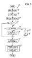
- the ECU 50 reads out a main program M shown by Fig. 4 from a ROM (not shown) to execute at a predetermined time interval period.
- the ECU 50 receives the throttle-opening signal St from the throttle sensor 60 and the wheel speed signals N1-N4 from the rotational speed sensors 61 (in step S1).
- a vehicle speed V is calculated based on the wheel speeds N1-N4 (in S2). It is preferable that the vehicle speed V is calculated as an average value of the wheel speeds N3 and N4 of the both rear wheels 15. Because the rear wheels 15 generally intend to slip compared with the front wheels 14 in a case that the front wheels 14 are always driven and the rear wheels 15 are not always driven.
- V (N3+N4)/2
- a rotational speed difference ⁇ N between the front wheels 14 and the rear wheels 15 is calculated based on the wheel speeds N1-N4 as a difference between an average value of the wheel speeds (N1, N2) of the front wheels 14 and an average value of that (N3, N4) of the rear wheels 15 (in step S3).
- ⁇ N (N1 + N2) / 2-
- N3 + N4) / 2 (N1 + N2 - N3 - N4) / 2
- step S4 it is judged whether the throttle-opening degree signal St is abnormal or not. In other words, it is judged whether the throttle-opening degree signal St exists within a predetermined range or not.
- the throttle-opening degree signal St is abnormal when the throttle-opening degree signal St is out of the predetermined range, i.e., when the above-mentioned expression is not satisfied.
- a pre-torque Tp corresponding to a first torque command of the claim description is obtained from the throttle-opening degree signal St and the vehicle speed V (in step S6).
- the pre-torque Tp is obtained by referring to a map that is stored in the ROM and defines values of the pre-torque Tp according to the throttle-opening degree signal St and the vehicle speed V.
- the map in the form of a three-dimension defines values of the pre-torque Tp so as to increase according to the increase of the throttle-opening degree signal St in a state that the vehicle speed V is less than a predetermined speed, while the map defines it so as to be constant independent of the throttle-opening degree signal St in a state that the vehicle speed V is larger than the predetermined speed.
- the pre-torque Tp is set to be zero in its value.
- a torque relative to a rotational speed difference torque (referred to as "RSD-torque” hereinafter) Tn corresponding to a second torque command of the claim description is obtained from the rotational speed difference ⁇ N and the vehicle speed V (in step S7).
- the RSD-torque Tn is obtained by referring a map that is stored in the ROM and defines values of RSD-torque according to the rotational speed difference ⁇ N and the vehicle speed V (in step S7).
- the map in the form of a three-dimension defines the values of the RSD-torque Tn so as to increase according to the increase of the rotational speed difference ⁇ N in a state that the vehicle speed V is less than a predetermined speed, but a proportion of the increase of the values of the RSD-torque Tn decreases according to the increase of the vehicle speed V in a state that the vehicle speed V is larger than the predetermined speed.
- an actual torque command Ta is calculated by the sum of the pre-torque Tp and the RSD-torque Tn, and a current value supplied to the electromagnetic coil 39 is controlled so that the torque transmission device 30 transmits from the input portion 31 to the output portion 32 the torque according to the actual torque command Ta (in step S8).
- Ta Tp + Tn
- the torque transmission device 30 is controlled corresponding to the pre-torque Tp and the RSD-torque Tn when the throttle-opening degree signal St is normal, while it is controlled corresponding to only the RSD-torque Tn when the throttle-opening degree signal St is abnormal.
- the throttle-opening degree signal St corresponding to how much a driver presses a throttle pedal is always detected by the throttle sensor 30 while the vehicle travels.
- the throttle-opening degree signal St is inputted to the ECU 50.
- the torque transmission device 30 is usually controlled corresponding to the pre-torque Tp and the RSD-torque (referred to as "a normal control mode" hereinafter). Then, the torque transmission device 30 is controlled according to the pre-torque Tp mainly under a state that the vehicle runs normally, because the rotational speed difference ⁇ N is small or zero.
- the throttle-opening degree signal St becomes to be abnormal because of a failure of the throttle sensor 60, a wire breaking or effect of some noise. Then, since the throttle-opening degree signal St becomes to be out of the predetermined range, the pre-torque Tp is made zero. Therefore, the torque transmission device 30 is controlled according to only the RSD-torque Tn (referred to as "a RSD control mode" hereinafter). Even if the throttle-opening signal degree St becomes to be abnormal when the vehicle travels on the rough road, since the torque transmission device 30 is controlled according to the RSD-torque Tn, the vehicle can run on the rough road in accordance with the RSD command mode.
- the throttle-opening degree signal St returns to be a normal state immediately. Then, the control of the torque transmission device 30 can be returned to the normal control mode.
- the vehicle can retain function as four-wheel-drive vehicle.
- the second embodiment is same as the first embodiment except that a main program M' is used for the second embodiment instead of the main program M in the first embodiment, description for other constructions are omitted.
- step (S11) for judging whether a flag F is one (active) or not is disposed in front of step (S4) for judging whether the throttle-opening signal degree St is or not the abnormal state.
- the flag F is set as zero initially just after an ignition is turned on, for example.
- the flag F keeps one (active), if it is set to one once unless the driver presses a reset button arranged in a cabin of the vehicle. In other words, the flag F is initialized to be zero when the reset button is turned.
- the vehicle is controlled stably.
- a third embodiment is same as the first embodiment except that a main program M" is used for the third embodiment instead of the main program M in the first embodiment, description for other constructions are omitted.
- step (S10) judging whether a predetermined time passes or not after the throttle-opening degree signal St returned to the normal state is disposed between step (S4) for judging the abnormality of the throttle-opening degree signal St and step (S6) for calculating the pre-torque Tp.
- a software timer is started. It is judged whether a value of the timer exceeds the predetermined time or not in step (S10).
- the value of the timer is initially set as a larger value than the predetermined value, because it prevents that the pre-torque Tp is set to zero in step (S5) at the first scan of the main program M" after the ignition is turned on.
- the control of the torque transmission device 30 is not returned to the normal control mode unless it passes the predetermined time after the throttle-opening signal degree St returns to the normal. Therefore, it is prevented that the normal control mode and the RSD control mode are repeatedly changed in a short period. Therefore, the vehicle is controlled stably.
- the reset button is not needed in comparison with the second embodiment.
- the front wheels 14 are always driven and the rear wheels 15 are selectively driven in the first, second and third embodiments.
- the present invention can be also applied to a four-wheel-drive vehicle that the rear wheels 16 are always driven and the front wheels 15 are selectively driven.
- the abnormality of the throttle-opening degree signal St is judged according to whether the throttle-opening degree signal St is in the predetermined range in the first, second and third embodiments.
- other ways can be applied to judge the abnormality of the throttle-opening degree signal St.
- the abnormality of the throttle-opening degree signal St is judged by using lengths of its drift cycle.
- the throttle-opening degree signal St is serial signal, it is possible that the abnormality is judged by whether the serial signal is received or not during a predetermined receiving cycle.
- the RSD-torque Tn is calculated by the same way, i.e., by using the same map, in both of the normal control mode and the RSD control mode in the first, second and third embodiments. However, different way or different map can be applied. Further, a value that is obtained so as to multiply the RSD-torque calculated as same way with the normal control mode by some gain can be used as RSD-torque in the RSD control mode.
- the four-wheel-drive vehicle has a torque transmission device configured to distribute torque transmitted from an engine to a first set of wheels to a second set of wheels. Throttle-opening of the engine is detected. A first torque command which depends on the throttle-opening is obtained. A rotational speed difference between the first set of wheels and the second set of wheels is detected. A second torque command which depends on the rotational speed difference is obtained. The torque transmission device is controlled based on the first and the second torque command so as to transmit the driving force to the second set of wheels according to the throttle-opening and the rotational speed difference. Then, a signal that corresponds to the throttle-opening is monitored. When the signal is judged being abnormal, the first torque command is ignored so that the torque transmission device is controlled based on the second torque command.
Landscapes
- Engineering & Computer Science (AREA)
- Chemical & Material Sciences (AREA)
- Combustion & Propulsion (AREA)
- Transportation (AREA)
- Mechanical Engineering (AREA)
- Arrangement And Driving Of Transmission Devices (AREA)
Abstract
Description
Claims (17)
- A driving force distribution control method for a four-wheel-drive vehicle having a torque transmission device configured to distribute torque transmitted from an engine to a first set of wheels directly driven and to a second set of wheels driven therethrough, the control method comprising the steps of:detecting throttle-opening of the engine;obtaining a first torque command which depends on the throttle-opening;detecting a rotational speed difference between the first set of wheels and the second set of wheels;obtaining a second torque command which depends on the rotational speed difference;controlling the torque transmission device based on the first torque command and the second torque command so as to transmit the driving force to the second set of wheels according to the throttle-opening and the rotational speed difference; andmonitoring a signal which corresponds to the throttle-opening, wherein when the signal is judged being abnormal, the first torque command is ignored so that the torque transmission device is controlled based on the second torque command.
- A driving force distribution control method according to claim 1, wherein when the signal returns to normal, the ignoring the first torque command is cancelled so that the torque transmission device is controlled based on the first torque command and the second torque command.
- A driving force distribution control method according to claim 2, wherein the ignoring the first torque command is cancelled when a reset button is pressed after the signal returns to normal.
- A driving force distribution control method according to claim 2, wherein the ignoring the first torque command is cancelled when a predetermined time passes after the signal returns to normal.
- A driving force distribution control method according to claim 1, wherein the first set of wheels is front wheels and the second set of wheels are rear wheels of the four-wheels-drive vehicle.
- A driving force distribution control method according to claim 1, wherein the first set of wheels is rear wheels and the second set of wheels are front wheels of the four-wheels-drive vehicle.
- A driving force distribution control method according to claim 1, wherein when a value of the signal becomes out of a predetermined range, the signal is judged to be abnormal.
- A driving force distribution control method according to claim 1, wherein when a length of drift cycle of the signal becomes shorter than a predetermined length, the signal is judged to be abnormal.
- A driving force distribution control method according to claim 1, wherein when the signal is not received during a predetermined period, the signal is judged to be abnormal.
- A driving force distribution control method according to claim 1, wherein vehicle speed of the four-wheel-drive vehicle is calculated based on at least one rotational speed of the first set of wheels and the second set of wheels, and the first torque command depends on not only the throttle-opening but also and the vehicle speed.
- A driving force distribution control method according to claim 10, wherein the first torque command is obtained by using a first map which describes a relationship between torque transmitted to the second set of wheels, the throttle-opening the vehicle speed.
- A driving force distribution control method according to claim 1, wherein vehicle speed of the four-wheel-drive vehicle is calculated based on at least one rotational speed of the first set of wheels and the second set of wheels, and the second torque command depends on not only the rotational speed difference but also the vehicle speed.
- A driving force distribution control method according to claim 12, wherein the second torque command is obtained by using a second map which describes a relationship between torque transmitted to the second set of wheels, the rotational speed difference and the vehicle speed.
- A driving force distribution apparatus for a four-wheel-drive vehicle having a torque transmission device configured to distribute torque transmitted from an engine to a first set of wheels driven directly and to a second set of wheels driven therethrough, the apparatus comprising:a throttle sensor detecting throttle-opening degree of the engine;plural speed sensors detecting rotational speed of the first set of wheels and the second set of wheels;an electrical control unit controlling the torque transmission device, wherein the electrical control unit determines a first torque command which depends on the throttle-opening detected by the throttle sensor and a second torque command which depends on a rotational speed difference between the first set of wheels and the second set of wheels detected by the each speed sensor, the electrical control unit controls the torque transmission device based on the first torque command and the second torque command so as to transmit the driving force to the second set of wheels according to the throttle-opening and the rotational speed difference, and the electrical control unit monitors a signal which is detected by the throttle sensor, and when the signal judged being abnormal the first torque command is ignored so that the torque transmission device is controlled based on the second torque command.
- A driving force distribution apparatus according to claim 15, wherein the torque transmission device comprises:a main clutch mechanism to transmit the torque to the second set of wheels,a cam mechanism to operate the main clutch mechanism, anda pilot clutch mechanism to operate the cam mechanism based on the first torque command and the second torque command.
- A driving force distribution apparatus for a four-wheel-drive vehicle having a torque transmission device configured to distribute torque transmitted from an engine to a first set of wheels to a second set of wheels, the apparatus comprising:throttle sensing means for detecting throttle-opening of the engine;rotational speed sensing means for detecting rotational speed of the first set of wheels and the second set of wheels;control means for controlling the torque transmission device, wherein the control means determines a first torque command which depends on the throttle-opening detected by the throttle sensing means and a second torque command which depends on a rotational speed difference between the first set of wheels and the second set of wheels detected by the rotational speed sensing means, the control means controls the torque transmission device based on the first torque command and the second torque command so as to transmit the driving force to the second set of wheels according to the throttle-opening and the rotational speed difference, and the control means monitors a signal which is detected by the throttle sensor, and when the signal judged being abnormal the first torque command is ignored so that the torque transmission device is controlled based on the second torque command.
- A driving force distribution apparatus according to claim 16, wherein the torque transmission device comprises:main clutch means for transmitting the torque to the second set of wheels;cam means for operating the main clutch means; andpilot clutch means for operating the cam means based on the first torque command and the second torque command.
Applications Claiming Priority (2)
| Application Number | Priority Date | Filing Date | Title |
|---|---|---|---|
| JP2002120134 | 2002-04-23 | ||
| JP2002120134A JP2003312286A (en) | 2002-04-23 | 2002-04-23 | Wheel driving force allocation controlling system |
Publications (3)
| Publication Number | Publication Date |
|---|---|
| EP1356976A2 true EP1356976A2 (en) | 2003-10-29 |
| EP1356976A3 EP1356976A3 (en) | 2004-10-27 |
| EP1356976B1 EP1356976B1 (en) | 2007-03-28 |
Family
ID=28786757
Family Applications (1)
| Application Number | Title | Priority Date | Filing Date |
|---|---|---|---|
| EP03009233A Expired - Lifetime EP1356976B1 (en) | 2002-04-23 | 2003-04-23 | Driving force distribution method and apparatus |
Country Status (4)
| Country | Link |
|---|---|
| US (1) | US6842682B2 (en) |
| EP (1) | EP1356976B1 (en) |
| JP (1) | JP2003312286A (en) |
| DE (1) | DE60312762T2 (en) |
Families Citing this family (6)
| Publication number | Priority date | Publication date | Assignee | Title |
|---|---|---|---|---|
| JP4432861B2 (en) * | 2005-08-22 | 2010-03-17 | トヨタ自動車株式会社 | Vehicle driving force control device |
| JP4969936B2 (en) * | 2006-07-28 | 2012-07-04 | 富士重工業株式会社 | Vehicle driving force distribution control device |
| JP5668441B2 (en) | 2010-12-07 | 2015-02-12 | 株式会社ジェイテクト | Driving force distribution control device |
| WO2013142980A1 (en) | 2012-03-30 | 2013-10-03 | Irdeto Canada Corporation | Securing accessible systems using variable dependent coding |
| US9434251B2 (en) | 2014-07-17 | 2016-09-06 | Honda Motor Co., Ltd. | All-wheel drive failsafe action axle torque calculation method |
| KR102323560B1 (en) * | 2017-08-08 | 2021-11-08 | 삼성전자주식회사 | Electronic device including circuit configured to adjust peak intensity of current |
Family Cites Families (7)
| Publication number | Priority date | Publication date | Assignee | Title |
|---|---|---|---|---|
| JP2591082B2 (en) * | 1988-07-07 | 1997-03-19 | 株式会社デンソー | Vehicle slip control device |
| JPH0725278B2 (en) * | 1988-08-31 | 1995-03-22 | 日産自動車株式会社 | Drive force distribution controller for four-wheel drive vehicle |
| JPH0729558B2 (en) * | 1989-04-10 | 1995-04-05 | 日産自動車株式会社 | Drive force distribution controller for four-wheel drive vehicle |
| JP2754721B2 (en) * | 1989-05-11 | 1998-05-20 | 日産自動車株式会社 | Vehicle fail-safe device |
| JP2915977B2 (en) * | 1990-09-07 | 1999-07-05 | 株式会社ゼクセル | Backup device for sensor for vehicle control device |
| GB9213178D0 (en) * | 1992-06-22 | 1992-08-05 | Lotus Car | Vehicle suspension system |
| JP4067062B2 (en) * | 1997-02-20 | 2008-03-26 | 株式会社デンソー | Electronic throttle control device for internal combustion engine |
-
2002
- 2002-04-23 JP JP2002120134A patent/JP2003312286A/en active Pending
-
2003
- 2003-04-23 US US10/420,892 patent/US6842682B2/en not_active Expired - Lifetime
- 2003-04-23 DE DE60312762T patent/DE60312762T2/en not_active Expired - Lifetime
- 2003-04-23 EP EP03009233A patent/EP1356976B1/en not_active Expired - Lifetime
Also Published As
| Publication number | Publication date |
|---|---|
| EP1356976B1 (en) | 2007-03-28 |
| DE60312762T2 (en) | 2008-01-24 |
| US6842682B2 (en) | 2005-01-11 |
| JP2003312286A (en) | 2003-11-06 |
| EP1356976A3 (en) | 2004-10-27 |
| DE60312762D1 (en) | 2007-05-10 |
| US20040019421A1 (en) | 2004-01-29 |
Similar Documents
| Publication | Publication Date | Title |
|---|---|---|
| EP2617596B1 (en) | Four-wheel-drive vehicle and control device for same | |
| US9701196B2 (en) | Four-wheel-drive vehicle | |
| US6575261B2 (en) | Drive-force distribution controller | |
| US8095288B2 (en) | Reducing oscillations in a motor vehicle driveline | |
| CN102166957A (en) | Vehicle driving state controlling means | |
| EP1104715B1 (en) | Drive-force distribution controller for a four-wheel-drive vehicle | |
| US7553255B2 (en) | Locker clutch control for a differential mechanism | |
| US6935455B2 (en) | Drive system control method and drive power transmission control system for vehicle | |
| EP1356976B1 (en) | Driving force distribution method and apparatus | |
| US20020179357A1 (en) | Automatic axle traction control | |
| US6845838B2 (en) | Four-wheel drive vehicle | |
| WO2016198510A1 (en) | Dog clutch having a sensor system | |
| US7721834B2 (en) | Prevention of inadvertent inertial engagement of a transfer case clutch | |
| EP1580463A2 (en) | System and method for detecting torque transmitted by a clutch in a vehicle | |
| US9902379B2 (en) | Controlling wheel hop in a vehicle axle | |
| US7290636B2 (en) | Device and method for controlling distribution of drive force of four-wheel drive car | |
| US6837329B2 (en) | Power distribution control method and apparatus for four-wheel drive vehicle | |
| US12187305B2 (en) | Powertrain torque control during shift to four-wheel drive in automated-driving mode | |
| US12617231B2 (en) | Electric actuable wheel hubs | |
| JP2004009814A (en) | Wheel driving force distribution control system | |
| US20230302848A1 (en) | Electric actuable wheel hubs | |
| JP2004017885A (en) | Front and rear wheel drive vehicle | |
| JPH08324271A (en) | Driving force distribution device for four-wheel drive vehicle | |
| WO2007022210A1 (en) | Torque transfer system |
Legal Events
| Date | Code | Title | Description |
|---|---|---|---|
| PUAI | Public reference made under article 153(3) epc to a published international application that has entered the european phase |
Free format text: ORIGINAL CODE: 0009012 |
|
| AK | Designated contracting states |
Kind code of ref document: A2 Designated state(s): AT BE BG CH CY CZ DE DK EE ES FI FR GB GR HU IE IT LI LU MC NL PT RO SE SI SK TR |
|
| AX | Request for extension of the european patent |
Extension state: AL LT LV MK |
|
| PUAL | Search report despatched |
Free format text: ORIGINAL CODE: 0009013 |
|
| AK | Designated contracting states |
Kind code of ref document: A3 Designated state(s): AT BE BG CH CY CZ DE DK EE ES FI FR GB GR HU IE IT LI LU MC NL PT RO SE SI SK TR |
|
| AX | Request for extension of the european patent |
Extension state: AL LT LV MK |
|
| 17P | Request for examination filed |
Effective date: 20050304 |
|
| AKX | Designation fees paid |
Designated state(s): DE FR GB |
|
| RAP1 | Party data changed (applicant data changed or rights of an application transferred) |
Owner name: JTEKT CORPORATION |
|
| GRAP | Despatch of communication of intention to grant a patent |
Free format text: ORIGINAL CODE: EPIDOSNIGR1 |
|
| RIN1 | Information on inventor provided before grant (corrected) |
Inventor name: KATO, KIYOSHIGE,C/O JTEKT CORPORATION Inventor name: WAKAO, HISAAKI,C/O JTEKT CORPORATION Inventor name: ITO, SATOMI,C/O JTEKT CORPORATION |
|
| GRAS | Grant fee paid |
Free format text: ORIGINAL CODE: EPIDOSNIGR3 |
|
| GRAA | (expected) grant |
Free format text: ORIGINAL CODE: 0009210 |
|
| AK | Designated contracting states |
Kind code of ref document: B1 Designated state(s): DE FR GB |
|
| REG | Reference to a national code |
Ref country code: GB Ref legal event code: FG4D |
|
| REF | Corresponds to: |
Ref document number: 60312762 Country of ref document: DE Date of ref document: 20070510 Kind code of ref document: P |
|
| PLBE | No opposition filed within time limit |
Free format text: ORIGINAL CODE: 0009261 |
|
| STAA | Information on the status of an ep patent application or granted ep patent |
Free format text: STATUS: NO OPPOSITION FILED WITHIN TIME LIMIT |
|
| 26N | No opposition filed |
Effective date: 20080102 |
|
| PGFP | Annual fee paid to national office [announced via postgrant information from national office to epo] |
Ref country code: GB Payment date: 20080423 Year of fee payment: 6 |
|
| GBPC | Gb: european patent ceased through non-payment of renewal fee |
Effective date: 20090423 |
|
| PG25 | Lapsed in a contracting state [announced via postgrant information from national office to epo] |
Ref country code: GB Free format text: LAPSE BECAUSE OF NON-PAYMENT OF DUE FEES Effective date: 20090423 |
|
| REG | Reference to a national code |
Ref country code: FR Ref legal event code: PLFP Year of fee payment: 14 |
|
| REG | Reference to a national code |
Ref country code: FR Ref legal event code: PLFP Year of fee payment: 15 |
|
| REG | Reference to a national code |
Ref country code: FR Ref legal event code: PLFP Year of fee payment: 16 |
|
| PGFP | Annual fee paid to national office [announced via postgrant information from national office to epo] |
Ref country code: FR Payment date: 20220308 Year of fee payment: 20 |
|
| PGFP | Annual fee paid to national office [announced via postgrant information from national office to epo] |
Ref country code: DE Payment date: 20220302 Year of fee payment: 20 |
|
| REG | Reference to a national code |
Ref country code: DE Ref legal event code: R071 Ref document number: 60312762 Country of ref document: DE |