EP1356959A1 - Tyre - Google Patents
Tyre Download PDFInfo
- Publication number
- EP1356959A1 EP1356959A1 EP02009016A EP02009016A EP1356959A1 EP 1356959 A1 EP1356959 A1 EP 1356959A1 EP 02009016 A EP02009016 A EP 02009016A EP 02009016 A EP02009016 A EP 02009016A EP 1356959 A1 EP1356959 A1 EP 1356959A1
- Authority
- EP
- European Patent Office
- Prior art keywords
- tyre
- tread
- recessed regions
- radial
- height
- Prior art date
- Legal status (The legal status is an assumption and is not a legal conclusion. Google has not performed a legal analysis and makes no representation as to the accuracy of the status listed.)
- Granted
Links
- 230000001934 delay Effects 0.000 description 1
- 230000001419 dependent effect Effects 0.000 description 1
- 238000001514 detection method Methods 0.000 description 1
- 238000004088 simulation Methods 0.000 description 1
Images

Classifications
-
- G—PHYSICS
- G01—MEASURING; TESTING
- G01M—TESTING STATIC OR DYNAMIC BALANCE OF MACHINES OR STRUCTURES; TESTING OF STRUCTURES OR APPARATUS, NOT OTHERWISE PROVIDED FOR
- G01M17/00—Testing of vehicles
- G01M17/007—Wheeled or endless-tracked vehicles
- G01M17/02—Tyres
-
- B—PERFORMING OPERATIONS; TRANSPORTING
- B60—VEHICLES IN GENERAL
- B60C—VEHICLE TYRES; TYRE INFLATION; TYRE CHANGING; CONNECTING VALVES TO INFLATABLE ELASTIC BODIES IN GENERAL; DEVICES OR ARRANGEMENTS RELATED TO TYRES
- B60C11/00—Tyre tread bands; Tread patterns; Anti-skid inserts
-
- B—PERFORMING OPERATIONS; TRANSPORTING
- B60—VEHICLES IN GENERAL
- B60C—VEHICLE TYRES; TYRE INFLATION; TYRE CHANGING; CONNECTING VALVES TO INFLATABLE ELASTIC BODIES IN GENERAL; DEVICES OR ARRANGEMENTS RELATED TO TYRES
- B60C11/00—Tyre tread bands; Tread patterns; Anti-skid inserts
- B60C11/03—Tread patterns
- B60C11/0311—Patterns comprising tread lugs arranged parallel or oblique to the axis of rotation
-
- B—PERFORMING OPERATIONS; TRANSPORTING
- B60—VEHICLES IN GENERAL
- B60C—VEHICLE TYRES; TYRE INFLATION; TYRE CHANGING; CONNECTING VALVES TO INFLATABLE ELASTIC BODIES IN GENERAL; DEVICES OR ARRANGEMENTS RELATED TO TYRES
- B60C19/00—Tyre parts or constructions not otherwise provided for
-
- B—PERFORMING OPERATIONS; TRANSPORTING
- B60—VEHICLES IN GENERAL
- B60C—VEHICLE TYRES; TYRE INFLATION; TYRE CHANGING; CONNECTING VALVES TO INFLATABLE ELASTIC BODIES IN GENERAL; DEVICES OR ARRANGEMENTS RELATED TO TYRES
- B60C19/00—Tyre parts or constructions not otherwise provided for
- B60C2019/006—Warning devices, e.g. devices generating noise due to flat or worn tyres
Definitions
- the present patent application relates to a tyre in accordance with the preamble of claim 1.
- the patent application relates to a tyre comprising a circumferential tread portion having a first radial tread height.
- One object of the invention is to provide a dealership tester or repair shop test staff affordable and simple means to aid in identification of probable sources of vibration induced noises on vehicles. This object is achieved by means of a tyre in accordance with the characterising portion of claim 1.
- Fig. 1 shows a simplified side view of a tyre 1.
- the tyre 1 is constituted of a conventional re-treaded tyre.
- a circumferential tread portion 2 having a first radial tread height is fitted to the tyre 1.
- the tread is of conventional type and normally comprise a tread pattern (not shown), which is arranged for normal running on a road surface.
- the tread portion 2 is provided with a plurality of recessed regions 3 having a second lower radial tread height.
- the recessed regions 3 extend laterally across the tread portion 2. Note that the radial difference in tread height is exaggerated in fig. 1 in order to clearly illustrate the recessed regions.
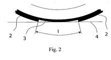
- Fig. 2 shows a partial side view of the tyre 1 and especially the geometry of a recessed region 3.
- the recessed regions 3 do not comprise a tread pattern while the circumferential thread portion 2 having the first radial tread height comprise a tread pattern.
- the length I in the circumferential direction of each of the recessed regions 3 are at least such that the tyre 1 can be rotated around its axis to ground contact on a plane surface 4 with a point of contact on the tread of a recessed region 3.
- the recessed regions 3 are symmetrically disposed around the perimeter of the tyre 1.
- the tyre 1 preferably has six recessed regions 3, but it is also conceivable to arrange any number of recessed regions 3 around the perimeter of the tyre 1, although the number preferably should lie between four and eight for the size of tyres normally used on ordinary cars in order to generate frequencies in a range between 0 and 40Hz useful for detection of vibration induced noises on vehicles.
- f [Hz] (v ⁇ n) / (c ⁇ 3.6) where: v is the velocity expressed in [km/h]; n is the number of recessed regions [integer]; c is the mean circumference of the tyre [m].
- f [Hz] (v ⁇ n) / (c ⁇ 2.24) where: v is the velocity expressed in [mph]; n is the number of recessed regions [integer]; c is the mean circumference of the tyre [m].
- the circumference of the tyre 1 is preferably about 1925 mm, and the tread portions 2 between the recessed regions 3 have a length in the circumferential direction of approximately 220 mm and the recessed regions 3 have a length in the circumferential direction of approximately 110 mm the radial height difference between the tread portions 2 having the first radial tread height and the recessed regions 3 having the second lower radial tread height being about 6 mm.
- the tread portions 2 between the recessed regions 3 have a length in the circumferential direction being approximately twice the length of the recessed regions 3 in the circumferential direction.
- the radial height difference between the first radial thread height and the second lower radial tread height preferably is in the range of 5-10 mm.
- the vehicle In order to detect vibration induced noises, the vehicle, with at least one tyre 1 according to the invention mounted thereto, is driven through a range of predetermined reference velocities, whereupon the tyre causes the vehicle to be vibrated at a range of different frequencies.
- the vehicle can be driven at low and moderate speeds in any way well known to the skilled person, without jeopardizing the safety of the driver.
- An appropriate range of velocities lie between 0-40 km/h or 0-25 mph.
- two tyres 1 are utilised, wherein the two tyres 1 alternative are mounted on a front or rear axle of the vehicle.
- the tyres can be mounted to a front or rear axle of the vehicle, as counted in the normal travelling direction of the vehicle, wherein a first test is performed with the tyres mounted to the front axle and a second with the tyres mounted to the rear axle.
- the motor vehicle can be provided with tyres for generating vibration induced noises on all axles.
Landscapes
- Engineering & Computer Science (AREA)
- Mechanical Engineering (AREA)
- Physics & Mathematics (AREA)
- General Physics & Mathematics (AREA)
- Tires In General (AREA)
Abstract
Description
- The present patent application relates to a tyre in accordance with the preamble of
claim 1. Particularly, the patent application relates to a tyre comprising a circumferential tread portion having a first radial tread height. - Motor vehicle manufacturers aim to eliminate rattles, squeaks and other undesired noises which might occur when a vehicle is in use. However, since these noises only occur when the vehicle is subjected to the vibrations occurring in use, it can be difficult to track down and correct the source of such noises.
- A number of different simulation systems have been developed to allow identification of noises on a test bed. Roller tests in which the stationary car has its wheel driven on sets of rollers, which have different surface texture and where the car can be subjected to different frequencies of vibration by changing the rotational speed of the rollers as well as test beds where the vehicle is supported on its wheels and a vibration generator is utilized for vibrating the wheel supporting means with a controlled frequency, are previously known. The purpose of such test beds is to determine the frequency at which a vibration induced noise occurs and utilise this information for determining the most probable cause of the noise. One such test bed system, where the cause of the noise is determined through comparing such frequency information with previously identified causes of noise at the determined frequency is previously known through EP 0 671 620.
- However, as a result of the complex nature of such test beds and consequently the substantial cost associated therewith, only a limited number of vehicle dealerships and repair shops are able to provide for such testing, causing time delays and high expenses for vehicle customers and dealers/vehicle manufacturers in resolving noise problems.
- One object of the invention is to provide a dealership tester or repair shop test staff affordable and simple means to aid in identification of probable sources of vibration induced noises on vehicles. This object is achieved by means of a tyre in accordance with the characterising portion of
claim 1. - Preferred embodiments are listed in the dependent claims.
- In the following, the invention will be described in greater detail with reference to attached drawings, in which
- Fig. 1 is a schematic illustration of a tyre according to a first embodiment of the invention,
- Fig. 2 is a schematic illustration of the geometry of the recessed regions of the tyre according to fig. 1.
-
- Fig. 1 shows a simplified side view of a
tyre 1. In a preferred embodiment of the invention, thetyre 1 is constituted of a conventional re-treaded tyre. Acircumferential tread portion 2 having a first radial tread height is fitted to thetyre 1. The tread is of conventional type and normally comprise a tread pattern (not shown), which is arranged for normal running on a road surface. - In order to ensure that the tyre generates vibrations at appropriate frequencies when the vehicle drives slowly, the
tread portion 2 is provided with a plurality ofrecessed regions 3 having a second lower radial tread height. Therecessed regions 3 extend laterally across thetread portion 2. Note that the radial difference in tread height is exaggerated in fig. 1 in order to clearly illustrate the recessed regions. - Fig. 2 shows a partial side view of the
tyre 1 and especially the geometry of arecessed region 3. In one embodiment of the invention, therecessed regions 3 do not comprise a tread pattern while thecircumferential thread portion 2 having the first radial tread height comprise a tread pattern. - As shown in fig. 2, in a preferred embodiment of the invention, the length I in the circumferential direction of each of the
recessed regions 3 are at least such that thetyre 1 can be rotated around its axis to ground contact on aplane surface 4 with a point of contact on the tread of arecessed region 3. - In one embodiment of the invention, the
recessed regions 3 are symmetrically disposed around the perimeter of thetyre 1. In this case, thetyre 1 preferably has sixrecessed regions 3, but it is also conceivable to arrange any number ofrecessed regions 3 around the perimeter of thetyre 1, although the number preferably should lie between four and eight for the size of tyres normally used on ordinary cars in order to generate frequencies in a range between 0 and 40Hz useful for detection of vibration induced noises on vehicles. - By means of measuring the velocity of the vehicle when a noise is identified, it is possible to approximate the frequency generated by the
tyre 1 and thereby to identify a probable source of the noise induced sound. In case the source of the sound is readily determinable to the tester, appropriate corrective measures can be undertaken immediately. This means that the time and effort for eliminating such a noise can be minimized. - It is possible to approximate the frequency generated by the
tyre 1 when causing the noise using only the velocity of the vehicle as reference. The frequency can then be calculated using the following equation: f [Hz]= (v × n) / (c × 3.6) where: v is the velocity expressed in [km/h]; n is the number of recessed regions [integer]; c is the mean circumference of the tyre [m]. In case of a vehicle only having means for presenting the velocity in miles per hour, the equation need only be modified as follows: f [Hz]= (v × n) / (c × 2.24) where: v is the velocity expressed in [mph]; n is the number of recessed regions [integer]; c is the mean circumference of the tyre [m]. - Furthermore, it is possible to build up a set of stored data which will indicate that, for example, when a noise occurs at a certain velocity it is likely to result from a certain vehicle component. In this way the tester is able to directly identify what parts of the vehicle he should check to try to counter the noise. Accordingly, the velocity at which the noise begins to occur can be noted, and the velocity at which the noise stops occurring can be noted and this information can be compared with stored data for the particular type of vehicle being tested and used to identify a probable source of the noise.
- In a preferred embodiment, the circumference of the
tyre 1 is preferably about 1925 mm, and thetread portions 2 between therecessed regions 3 have a length in the circumferential direction of approximately 220 mm and therecessed regions 3 have a length in the circumferential direction of approximately 110 mm the radial height difference between thetread portions 2 having the first radial tread height and therecessed regions 3 having the second lower radial tread height being about 6 mm. - In a further embodiment of the invention, the
tread portions 2 between therecessed regions 3 have a length in the circumferential direction being approximately twice the length of therecessed regions 3 in the circumferential direction. - In yet a further embodiment of the invention, the radial height difference between the first radial thread height and the second lower radial tread height preferably is in the range of 5-10 mm.
- In order to detect vibration induced noises, the vehicle, with at least one
tyre 1 according to the invention mounted thereto, is driven through a range of predetermined reference velocities, whereupon the tyre causes the vehicle to be vibrated at a range of different frequencies. During testing the vehicle can be driven at low and moderate speeds in any way well known to the skilled person, without jeopardizing the safety of the driver. An appropriate range of velocities lie between 0-40 km/h or 0-25 mph. - Preferably, two
tyres 1 are utilised, wherein the twotyres 1 alternative are mounted on a front or rear axle of the vehicle. Accordingly, the tyres can be mounted to a front or rear axle of the vehicle, as counted in the normal travelling direction of the vehicle, wherein a first test is performed with the tyres mounted to the front axle and a second with the tyres mounted to the rear axle. In order to accomplish vibration of the whole vehicle at the same time, the motor vehicle can be provided with tyres for generating vibration induced noises on all axles. - The invention is not limited to the above-described embodiments, but may be varied within the scope of the following claims.
Claims (8)
- A tyre (1) comprising a circumferential tread portion (2) having a first radial tread height,
characterised in that the tread portion (2) further is provided with a plurality of recessed regions (3) having a second lower radial tread height, which recessed regions (3) extend laterally across the tread portion (2) and have a length in the circumferential direction at least such that the tyre (1) can be rotated around its axis to ground contact on a plane surface (4) with a point of contact on the tread of a recessed region (3). - A tyre (1) according to claim 1,
characterised in that the recessed regions (3) are symmetrically disposed around the perimeter of the tyre (1). - A tyre (1) according to any one of claims 1 or 2,
characterised in that the tyre (1) preferably has six recessed regions (3). - A tyre (1) according to any one of claims 1 or 2,
characterised in that the tyre (1) preferably has between four and eight recessed regions (3). - A tyre (1) according to any one of claims 1-4,
characterised in that the radial height difference between the first radial tread height and the second lower radial tread height preferably is in the range of 5-10 mm. - A tyre (1) according to any one of claims 2 or 3,
characterised in that the circumference of the tyre (1) is preferably about 1925 mm, and that the tread portions (2) between the recessed regions have a length in the circumferential direction being approximately 220 mm and that the recessed regions (3) have a length in the circumferential direction being approximately 110 mm the radial height difference between the first radial tread height and the second lower radial tread height being about 6 mm. - A tyre (1) according to any one of claims 1-6,
characterised in that the tread portions (2) between the recessed regions (3) have a length in the circumferential direction being approximately twice the length of the recessed regions (3) in the circumferential direction. - A tyre (1) according to any one of claims 1-7,
characterised in that the recessed regions (3) does not comprise a tread pattern while the circumferential tread portion (2) having the first radial tread height comprise a tread pattern.
Priority Applications (2)
| Application Number | Priority Date | Filing Date | Title |
|---|---|---|---|
| EP20020009016 EP1356959B1 (en) | 2002-04-23 | 2002-04-23 | Tyre |
| DE2002609586 DE60209586T2 (en) | 2002-04-23 | 2002-04-23 | tires |
Applications Claiming Priority (1)
| Application Number | Priority Date | Filing Date | Title |
|---|---|---|---|
| EP20020009016 EP1356959B1 (en) | 2002-04-23 | 2002-04-23 | Tyre |
Publications (2)
| Publication Number | Publication Date |
|---|---|
| EP1356959A1 true EP1356959A1 (en) | 2003-10-29 |
| EP1356959B1 EP1356959B1 (en) | 2006-03-08 |
Family
ID=28685880
Family Applications (1)
| Application Number | Title | Priority Date | Filing Date |
|---|---|---|---|
| EP20020009016 Expired - Lifetime EP1356959B1 (en) | 2002-04-23 | 2002-04-23 | Tyre |
Country Status (2)
| Country | Link |
|---|---|
| EP (1) | EP1356959B1 (en) |
| DE (1) | DE60209586T2 (en) |
Citations (1)
| Publication number | Priority date | Publication date | Assignee | Title |
|---|---|---|---|---|
| JPH11208220A (en) * | 1998-01-27 | 1999-08-03 | Bridgestone Corp | Pneumatic tire |
-
2002
- 2002-04-23 DE DE2002609586 patent/DE60209586T2/en not_active Expired - Lifetime
- 2002-04-23 EP EP20020009016 patent/EP1356959B1/en not_active Expired - Lifetime
Patent Citations (1)
| Publication number | Priority date | Publication date | Assignee | Title |
|---|---|---|---|---|
| JPH11208220A (en) * | 1998-01-27 | 1999-08-03 | Bridgestone Corp | Pneumatic tire |
Non-Patent Citations (1)
| Title |
|---|
| PATENT ABSTRACTS OF JAPAN vol. 1999, no. 13 30 November 1999 (1999-11-30) * |
Also Published As
| Publication number | Publication date |
|---|---|
| DE60209586D1 (en) | 2006-05-04 |
| DE60209586T2 (en) | 2007-07-12 |
| EP1356959B1 (en) | 2006-03-08 |
Similar Documents
| Publication | Publication Date | Title |
|---|---|---|
| US7233237B2 (en) | Method and system or central station for monitoring tyre condition, and for detecting the presence of chains or nails, on a vehicle | |
| JP5027260B2 (en) | Tire pressure monitoring based on tire pressure classification | |
| JP4505165B2 (en) | Method for predicting comfort performance of a vehicle with a suspension system | |
| US7522032B2 (en) | Method for detecting decrease in inner pressure of tire using GPS speed information | |
| RU2096746C1 (en) | Method of decrease of tendency of tire and wheel unit to cause vibration in plane perpendicular to axis of its rotation, process of manufacture of tire and wheel unit and equipment to determine additional static disbalance | |
| CN103797348A (en) | Method and device for diagnosing defects in components of a chassis system of a motor vehicle | |
| JP2005008039A (en) | Tire pressure monitoring device | |
| AU756307B2 (en) | Method and device for detecting a tyre flat running condition, inserts, wheels and tyres therefor | |
| JP2009513945A (en) | Method for detecting the internal pressure of a vehicle tire | |
| US7272536B2 (en) | Failure warning for a tire among a plurality of tires | |
| JP2012112781A (en) | Test apparatus for testing vibration characteristic of tire and test method using the test apparatus | |
| Siegel et al. | Smartphone-based wheel imbalance detection | |
| US6836706B2 (en) | Method of forecasting comfort inside a vehicle equipped with a mounted assembly having non-uniformities | |
| US7941255B2 (en) | Process and apparatus for detecting damper damage | |
| EP1356959B1 (en) | Tyre | |
| Potts et al. | Tire vibration studies: The state of the art | |
| US20040148074A1 (en) | System and method for monitoring the vehicle dynamics of a vehicle | |
| Li | Tire/road noise separation: tread pattern noise and road texture noise | |
| JP3136801B2 (en) | Tire pressure detector | |
| Hryciów et al. | Assessment of the effect of passenger car wheel unbalance on driving comfort | |
| JP3147472B2 (en) | Tire pressure detector | |
| JP3095095B2 (en) | Tire abnormal wear detection device | |
| JPH06328920A (en) | Tire pneumatic pressure detector | |
| CN114858473B (en) | First-order vibration noise evaluation method and system for passenger car drive train | |
| JPS62244704A (en) | Matching method for rim and tire |
Legal Events
| Date | Code | Title | Description |
|---|---|---|---|
| PUAI | Public reference made under article 153(3) epc to a published international application that has entered the european phase |
Free format text: ORIGINAL CODE: 0009012 |
|
| AK | Designated contracting states |
Kind code of ref document: A1 Designated state(s): AT BE CH CY DE DK ES FI FR GB GR IE IT LI LU MC NL PT SE TR |
|
| AX | Request for extension of the european patent |
Extension state: AL LT LV MK RO SI |
|
| 17P | Request for examination filed |
Effective date: 20040107 |
|
| 17Q | First examination report despatched |
Effective date: 20040420 |
|
| AKX | Designation fees paid |
Designated state(s): DE GB SE |
|
| GRAP | Despatch of communication of intention to grant a patent |
Free format text: ORIGINAL CODE: EPIDOSNIGR1 |
|
| GRAS | Grant fee paid |
Free format text: ORIGINAL CODE: EPIDOSNIGR3 |
|
| GRAA | (expected) grant |
Free format text: ORIGINAL CODE: 0009210 |
|
| RIC1 | Information provided on ipc code assigned before grant |
Ipc: G01M 7/02 20060101ALI20060110BHEP Ipc: B60C 11/03 20060101ALI20060110BHEP Ipc: B60C 19/00 20060101AFI20060110BHEP Ipc: B60C 11/00 20060101ALI20060110BHEP |
|
| AK | Designated contracting states |
Kind code of ref document: B1 Designated state(s): DE GB SE |
|
| REG | Reference to a national code |
Ref country code: GB Ref legal event code: FG4D |
|
| REF | Corresponds to: |
Ref document number: 60209586 Country of ref document: DE Date of ref document: 20060504 Kind code of ref document: P |
|
| REG | Reference to a national code |
Ref country code: SE Ref legal event code: TRGR |
|
| RAP2 | Party data changed (patent owner data changed or rights of a patent transferred) |
Owner name: FORD GLOBAL TECHNOLOGIES, LLC. |
|
| PLBE | No opposition filed within time limit |
Free format text: ORIGINAL CODE: 0009261 |
|
| STAA | Information on the status of an ep patent application or granted ep patent |
Free format text: STATUS: NO OPPOSITION FILED WITHIN TIME LIMIT |
|
| 26N | No opposition filed |
Effective date: 20061211 |
|
| PGFP | Annual fee paid to national office [announced via postgrant information from national office to epo] |
Ref country code: GB Payment date: 20110328 Year of fee payment: 10 Ref country code: SE Payment date: 20110406 Year of fee payment: 10 Ref country code: DE Payment date: 20110427 Year of fee payment: 10 |
|
| REG | Reference to a national code |
Ref country code: GB Ref legal event code: 732E Free format text: REGISTERED BETWEEN 20120510 AND 20120516 |
|
| REG | Reference to a national code |
Ref country code: GB Ref legal event code: 732E Free format text: REGISTERED BETWEEN 20120517 AND 20120523 |
|
| REG | Reference to a national code |
Ref country code: SE Ref legal event code: EUG |
|
| GBPC | Gb: european patent ceased through non-payment of renewal fee |
Effective date: 20120423 |
|
| PG25 | Lapsed in a contracting state [announced via postgrant information from national office to epo] |
Ref country code: GB Free format text: LAPSE BECAUSE OF NON-PAYMENT OF DUE FEES Effective date: 20120423 |
|
| REG | Reference to a national code |
Ref country code: DE Ref legal event code: R119 Ref document number: 60209586 Country of ref document: DE Effective date: 20121101 |
|
| PG25 | Lapsed in a contracting state [announced via postgrant information from national office to epo] |
Ref country code: SE Free format text: LAPSE BECAUSE OF NON-PAYMENT OF DUE FEES Effective date: 20120424 |
|
| PG25 | Lapsed in a contracting state [announced via postgrant information from national office to epo] |
Ref country code: DE Free format text: LAPSE BECAUSE OF NON-PAYMENT OF DUE FEES Effective date: 20121101 |