EP1355467A1 - Orthogonal frequency division multiplexing (OFDM) system with channel transfer function prediction - Google Patents
Orthogonal frequency division multiplexing (OFDM) system with channel transfer function prediction Download PDFInfo
- Publication number
- EP1355467A1 EP1355467A1 EP02008586A EP02008586A EP1355467A1 EP 1355467 A1 EP1355467 A1 EP 1355467A1 EP 02008586 A EP02008586 A EP 02008586A EP 02008586 A EP02008586 A EP 02008586A EP 1355467 A1 EP1355467 A1 EP 1355467A1
- Authority
- EP
- European Patent Office
- Prior art keywords
- channel
- transfer function
- ofdm
- downlink signal
- zero points
- Prior art date
- Legal status (The legal status is an assumption and is not a legal conclusion. Google has not performed a legal analysis and makes no representation as to the accuracy of the status listed.)
- Granted
Links
- 238000012546 transfer Methods 0.000 title claims abstract description 72
- 230000003044 adaptive effect Effects 0.000 claims abstract description 45
- 238000005562 fading Methods 0.000 claims abstract description 38
- 238000004891 communication Methods 0.000 claims abstract description 31
- 230000033001 locomotion Effects 0.000 claims abstract description 23
- 230000004044 response Effects 0.000 claims abstract description 22
- 230000001771 impaired effect Effects 0.000 claims abstract description 8
- 238000000034 method Methods 0.000 claims description 45
- 238000010586 diagram Methods 0.000 claims description 30
- 230000005540 biological transmission Effects 0.000 claims description 26
- 238000001228 spectrum Methods 0.000 claims description 10
- 238000006243 chemical reaction Methods 0.000 claims description 4
- 238000011156 evaluation Methods 0.000 claims description 3
- 238000012545 processing Methods 0.000 claims description 3
- 230000008054 signal transmission Effects 0.000 claims description 3
- 230000000694 effects Effects 0.000 claims description 2
- 230000010363 phase shift Effects 0.000 claims 3
- 230000006870 function Effects 0.000 description 45
- 230000001419 dependent effect Effects 0.000 description 8
- 230000006978 adaptation Effects 0.000 description 5
- 238000013459 approach Methods 0.000 description 5
- 230000008901 benefit Effects 0.000 description 4
- 238000013461 design Methods 0.000 description 4
- 210000004556 brain Anatomy 0.000 description 3
- 230000007423 decrease Effects 0.000 description 3
- 230000006735 deficit Effects 0.000 description 3
- 238000005259 measurement Methods 0.000 description 3
- 230000008569 process Effects 0.000 description 3
- 238000011160 research Methods 0.000 description 3
- 230000003595 spectral effect Effects 0.000 description 3
- 230000009466 transformation Effects 0.000 description 3
- 230000008859 change Effects 0.000 description 2
- 230000003111 delayed effect Effects 0.000 description 2
- 239000006185 dispersion Substances 0.000 description 2
- 238000002592 echocardiography Methods 0.000 description 2
- 230000007246 mechanism Effects 0.000 description 2
- 238000010295 mobile communication Methods 0.000 description 2
- 238000005457 optimization Methods 0.000 description 2
- 101150012579 ADSL gene Proteins 0.000 description 1
- 102100020775 Adenylosuccinate lyase Human genes 0.000 description 1
- 108700040193 Adenylosuccinate lyases Proteins 0.000 description 1
- 230000002411 adverse Effects 0.000 description 1
- 239000000969 carrier Substances 0.000 description 1
- 230000015556 catabolic process Effects 0.000 description 1
- 230000001413 cellular effect Effects 0.000 description 1
- 238000012937 correction Methods 0.000 description 1
- 230000002596 correlated effect Effects 0.000 description 1
- 230000005574 cross-species transmission Effects 0.000 description 1
- 230000007812 deficiency Effects 0.000 description 1
- 238000006731 degradation reaction Methods 0.000 description 1
- 230000002939 deleterious effect Effects 0.000 description 1
- 238000011161 development Methods 0.000 description 1
- 238000005516 engineering process Methods 0.000 description 1
- 230000002349 favourable effect Effects 0.000 description 1
- 230000006872 improvement Effects 0.000 description 1
- 239000000203 mixture Substances 0.000 description 1
- 230000008450 motivation Effects 0.000 description 1
- 230000035945 sensitivity Effects 0.000 description 1
- 230000011664 signaling Effects 0.000 description 1
- 238000004088 simulation Methods 0.000 description 1
- 230000003068 static effect Effects 0.000 description 1
- 230000001360 synchronised effect Effects 0.000 description 1
- 230000002123 temporal effect Effects 0.000 description 1
Images


Classifications
-
- H—ELECTRICITY
- H04—ELECTRIC COMMUNICATION TECHNIQUE
- H04L—TRANSMISSION OF DIGITAL INFORMATION, e.g. TELEGRAPHIC COMMUNICATION
- H04L25/00—Baseband systems
- H04L25/02—Details ; arrangements for supplying electrical power along data transmission lines
- H04L25/0202—Channel estimation
- H04L25/022—Channel estimation of frequency response
-
- H—ELECTRICITY
- H04—ELECTRIC COMMUNICATION TECHNIQUE
- H04L—TRANSMISSION OF DIGITAL INFORMATION, e.g. TELEGRAPHIC COMMUNICATION
- H04L25/00—Baseband systems
- H04L25/02—Details ; arrangements for supplying electrical power along data transmission lines
- H04L25/0202—Channel estimation
- H04L25/0204—Channel estimation of multiple channels
-
- H—ELECTRICITY
- H04—ELECTRIC COMMUNICATION TECHNIQUE
- H04L—TRANSMISSION OF DIGITAL INFORMATION, e.g. TELEGRAPHIC COMMUNICATION
- H04L27/00—Modulated-carrier systems
- H04L27/26—Systems using multi-frequency codes
- H04L27/2601—Multicarrier modulation systems
- H04L27/2626—Arrangements specific to the transmitter only
- H04L27/2627—Modulators
- H04L27/2637—Modulators with direct modulation of individual subcarriers
Definitions
- the underlying invention generally relates to the field of wireless communication systems with high-speed mobile access, especially to Orthogonal Frequency Division Multiplexing (OFDM) systems considering channel estimation and/or channel tracking. More particularly, the invention provides an adaptive subcarrier loading function for a mobile receiver in a wireless communication system based on OFDM that can advantageously be applied to predict the channel transfer function H ( j ⁇ ⁇ ,t ) of a multipath propagation channel being severely impaired by frequency-selective fading and an extremely time-variant behavior by detecting the position and/or movement of zero points of said transfer function H ( j ⁇ ,t ), thereby reducing the probability of an incorrect assignment of the modulation scheme for each subcarrier, that is caused by mobile terminals moving at high velocity.
- OFDM Orthogonal Frequency Division Multiplexing
- AOFDM Adaptive Orthogonal Frequency Division Multiplexing
- the system scenario is the one typical for domestic environments with a short range (within 20 meters). This scenario could be characterized by a set of terminals that needs to exchange data and to communicate with the external world.
- the requested modem platform has then to support different kinds of services, voice, data or video, with the possibility of transmitting both in a synchronous (for real-time applications) and an asynchronous way.
- a modem requirement is the capability of supporting variable bit rates in the range of 64 kBit/s to 100 MBit/s of payload, in order to create a multi-technological platform, available for different applications.
- the frequency band around 2.4 GHz and 5 GHz have already been used by other wireless transmission standards, such as IEEE-802.11 and HiperLAN/2 and are close to saturation.
- IEEE-802.11 and HiperLAN/2 are close to saturation.
- the expectation of the 17 GHz unlicensed frequency band seems to be a promising and challenging solution.
- the whole available spectrum (17.1 to 17.3 GHz) will be divided into four 50 MHz-width channels, which are not simultaneously selectable.
- the considered AOFDM modulation scheme has been designed to efficiently transmit in one of these channels.
- Wireless links can be described by the presence of multiple signal paths between the transmitter and the receiver. These multipath components are generated whenever signals are reflected by objects in the environment such as buildings, walls, ceilings, mountains, cars, people, etc. Differences in reflected path lengths cause impulsive signal transmissions to arrive at the receiver with a finite temporal scattering, which is called the root mean square (RMS) delay spread ⁇ of the multipath propagation channel. With the aid of ⁇ , the approximate duration of the channel "echoes" resulting from multipath arrivals can be measured.
- RMS root mean square
- Time-dispersive channels generate at least two potentially deleterious effects at the receiver, namely frequency-selective amplitude, phase variations and intersymbol interference (ISI).
- Frequency-dependent variations are caused by (randomly) delayed signal components adding out of phase at the receiver. Since the spectral location of fades is strongly dependent on the signal phase, the overall channel impulse response is highly sensitive to changes in the location and orientation of the receiver. Meanwhile, ISI occurs whenever delayed arrivals from one symbol interval "spill over" into subsequent symbol intervals. Thereby, ISI impedes the ability of the receiver to distinguish the desired signal from the echoes of previously transmitted symbols. The impact of both channel selectivity and ISI primarily depends on whether the system uses narrowband or wideband signaling.
- Wireless channels are subject to time-varying behavior.
- One of the distinguishing features of wireless links is the magnitude and rate at which these variations occur.
- An important measure of variability for a wireless channel is the coherence time T coh - the interval during which the impulse response of the multipath propagation channel remains correlated.
- T coh provides a measure of the rate at which variations in the wireless link occur.
- Channels are described as “fast fading” or “slow fading” depending on the length of the coherence time T coh relative to a single symbol interval:
- a slowly changing channel has a large coherence time T coh or, equivalently, a small Doppler spread B D , and vice versa.
- the channel coherence time T coh is strongly dependent on the rate of motion for the transmitter, receiver, and other objects in the environment.
- the fading rate directly affects the responsitivity and dynamic range requirements of the receiver.
- the fading rate primarily impacts the required convergence rate for adaptive receiver algorithms.
- Wireless designs often guarantee adequate performance under "worst-case” conditions, by limiting the achievable performance under more favorable conditions.
- One solution would be to exploit time-varying channel knowledge to provide optimized time-varying performance. This approach requires both channel estimation and adaptive receiver implementation, but offers the promise of substantial performance gains. Of course, the larger and faster the link variations, the more difficult (and computationally intensive) the tasks of estimation and adaptation become. Hence, the receiver consumes more energy. Because channel modeling is an active area of wireless research, a wide variety of models - both empirical and statistical - have been developed to characterize the channel impairments described above.
- the dominant impairment is the fading, which is connected with a multipath propagation environment.
- the electromagnetic waves are perturbed by structures, walls and furniture inside the building in such a way that the modulated signal propagates along several paths that connect the transmitter with the receiver.
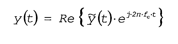
- the received signal y ( t ) can be viewed as the composition of a continuum of signal replicas:
- the received narrowband signal has a complex envelope ( t ) which can be expressed by means of the following convolution integral:
- the diffuse multipath model can be represented in baseband as a tapped-delay line (TDL) with time-varying complex coefficients and a fixed tap spacing 1/ B , where B is the passband signal bandwidth.
- B is the passband signal bandwidth.
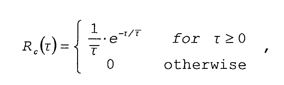
- the Power Delay Profile R c ( ⁇ ) characterizes the fading channel and measures the mean signal power relative to its dispersion across time.
- Several forms have been suggested for a decaying Power Delay Profile that models different fading channels.
- the decaying Power Delay Profile could reasonable be described by an exponential distribution. Therefore, the considered Power Delay Profile is given by wherein ⁇ denotes the mean delay.
- ⁇ is determined by the physical environments, and it is assumed to be about 50 ns for an indoor link at 17 GHz frequency band.
- the length of the TDL is determined by the delay spread ⁇ , which is defined as the range of ⁇ for which the delay profile R c ( ⁇ ) is essentially non-zero.
- the length is therefore given by the nearest integer of ⁇ B+ 1, wherein B is the passband signal bandwidth and ⁇ can reasonably assumed to be about 200 ns.
- the tap gains are independent complex Gaussian processes, whose variances are determined according to the Power Delay Profile R c ( ⁇ ).
- OFDM Adaptive Orthogonal Frequency Division Multiplex
- OFDM Orthogonal Frequency Division Multiplexing
- each sub-channel is relatively narrowband and is assumed to have flat fading.
- a given sub-channel has a low power, which results in a large bit error ratio (BER).
- BER bit error ratio
- time-varying channels there is a decorrelation time associated with each frequency-selective channel instance.
- a new adaptation must be implemented each time the channel decorrelates. Since the channel is slowly time-varying, the receiver can provide reliable channel state information to its transmitter using a robust feedback channel. For this reason, loading modulation schemes according to the channel response of each subcarrier seems to be an interesting approach for increasing the capacity usage of the channel.
- each user is allocated a pre-determined time slot or frequency band, respectively, to apply OFDM with adaptive modulation. Consequently, these unused subcarriers (as a result of adaptive modulation) within the allocated time slot or frequency band of the respective user are wasted and can not be used by other users.
- TDMA Time Division Multiple Access
- FDMA Frequency Division Multiple Access
- the main object of an adaptive subcarrier loading function is to assign the modulation scheme of each subcarrier according to the channel impulse response which can be determined by frequency-selective channel distortion.
- a lower modulation scheme such as BPSK
- a higher modulation scheme e.g. Quadrature Amplitude Modulation (QAM) with a 16- or 64-point signal constellation - is assigned.
- QAM Quadrature Amplitude Modulation
- the communication system between an access point 401 (AP) and a mobile terminal 405 (MT) capable of executing this function comprises the following steps:
- the channel transfer function H ( j ⁇ ,t ) is changing fast. Compared to the changing of H ( j ⁇ ,t ), the time duration between the timing of its measurement and the timing of a transmission according to a new modulation scheme assignment plan should be longer to guarantee a correct assignment. Otherwise, an incorrect assignment of the employed modulation scheme for said subcarriers might occur.
- pilot-pattern-based channel estimation and/or channel tracking there are different solutions to the problem of pilot-pattern-based channel estimation and/or channel tracking available, each of them being optimized to a specific application environment given by the transmission channel. Since the underlying invention is basically dedicated to pilot-assisted multi-carrier systems such as OFDM, it is necessary to briefly describe the main principles and techniques of conventional OFDM systems according to the state of the art.
- OFDM techniques are used in several wireless communication systems, e.g. in Wireless Local Area Networks (LANs) such as HiperLAN/2 and IEEE 801.11a.
- LANs Wireless Local Area Networks
- LANs Wireless Local Area Networks
- Fig. 1 the spectrum of an OFDM symbol and the applied modulation schemes for its subcarriers are shown in Fig. 1.
- an OFDM symbol 101 is split up into several subcarriers 102.
- subcarriers 102 In case of HIPERLAN/2, their number is 52 (with the exception of the component at 0 Hz).
- each subcarrier is modulated by means of a digital modulation technique.
- modulation schemes that can be applied to each subcarrier of an OFDM symbol, e.g.
- 16-QAM and 64-QAM are able to carry at once, respectively.
- M represents the number of signal points.
- the bit error rate (BER) becomes higher on the same noise or distortion condition (linear or non-linear).
- FIG. 3 A block diagram for a mobile transmission and reception system supporting wireless communication over a multipath propagation channel 320 with the aid of a pilot-assisted wireless multi-carrier system (here: an OFDM system) comprising means for a channel estimation according to the state of the art is shown in Fig. 3.
- a pilot-assisted wireless multi-carrier system here: an OFDM system
- the user data is fed to a channel encoder 303.
- the output data of said channel encoder is converted from serial to parallel according to the number of bits per subcarrier in one OFDM symbol.
- serial-to-parallel converter 304 is then modulated by a modulator 305, converted from frequency domain to time domain by an Inverse Fast Fourier Transform (IFFT, 306), and then submitted to a digital-to-analog conversion by a digital-to-analog converter (DAC, 307).
- IFFT Inverse Fast Fourier Transform
- DAC digital-to-analog converter
- the output of said DAC 307 is then up-converted to the passband by using an RF block 308, supplied to a transmitting (TX) antenna 309 and radiated to the air.
- the radiated signal propagates through several paths (here: the paths 403 and 404), which are modeled as a multipath fading channel 320 that causes frequency-selective distortion.
- the received signal is amplified, down-converted to the baseband by another RF block 312 and supplied to an analog-to-digital converter (ADC, 313).
- ADC analog-to-digital converter
- the output of said ADC 313 is then transformed from time domain to frequency domain by a Fast Fourier Transform (FFT, 314).
- FFT Fast Fourier Transform
- a channel estimator 318 estimates the current channel transfer function H ( j ⁇ ,t ) of said multipath fading channel 320.
- the output data of said FFT 314 along with the frequency-selective distortion caused by said channel 320 is compensated by using an estimated channel transfer function H and ( j ⁇ ,t ) and supplied to a parallel-to-serial converter 316.
- the output of said parallel-to-serial converter 316 is then fed to a channel decoder 317, and the user data is derived.
- Fig. 4 shows a typical example of a propagation model with one access point 401 (AP) and one moving mobile terminal 405 (MT).
- AP access point
- MT moving mobile terminal
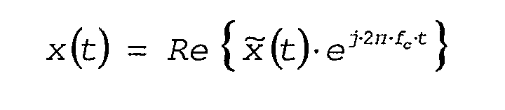
- the transmitted RF signal x ( t ) is radiated from an antenna 402 of the AP 401 (401).
- the signal propagates via several paths (here designated with 403 and 404) caused by reflection at mountains, trees, buildings or other objects.
- a receiver side e.g.
- the channel transfer function H ( s,t ) is derived as follows: thereby using wherein
- the channel transfer function H ( s,t ) can be described by using a polynomial of m-th order: wherein
- m is determined according to the power delay profile R c ( ⁇ ) of the underlying mobile radio channel.
- the receiver must be able to instantaneously estimate the actual channel transfer function H ( j ⁇ ,t ).
- Fig. 7 the frame structure of HiperLAN/2 is illustrated. Thereby, three preamble sections 701, 702, and 703 (A, B, and C) are added in front of the data block 704. These preambles 701, 702, and 703 are modulated by a known scrambling sequence SC consisting of 53 scrambling elements SC n ⁇ ⁇ -1, 0, +1 ⁇ .
- SC scrambling sequence
- -26 ⁇ n ⁇ +26 ⁇ : ⁇ +1,+1,-1,-1,+1,+1,-1,+1,+1,+1,+1, +1,+1,+1,+1,+1,+1, 0, +1,-1,-1,+1,+1,-1,+1,-1,+1,-1,-1,-1,-1, -1,+1,+1,+1,+1,+1 ⁇ .
- T SC ( j ⁇ ) A T ⁇ SC n ⁇ ( ⁇ - n ⁇ s - ⁇ c ), wherein
- Fig. 6 presents a block diagram 600 for a mobile transmission and reception system supporting wireless communication over a multipath propagation channel 620 by means of a pilot-assisted wireless multi-carrier system (here: an OFDM system) comprising means 618 for a channel estimation, which can be used for an adaptive subcarrier loading.
- a pilot-assisted wireless multi-carrier system here: an OFDM system
- FIG. 8 A sequence chart of a conventional subcarrier loading technique showing the data transfer between the access point 401 (AP) and the mobile terminal 405 (MT) according to the state of the art is depicted in Fig. 8.
- the underlying OFDM system is based on a Time Division Duplex (TDD) system, in which the same frequency is used for the uplink signal and the downlink signal.
- TDD Time Division Duplex
- the MT 405 receives the downlink signal of the AP 401, and estimates the transfer function of the channel.
- the MT 405 makes the proposal of a modulation scheme according to the channel estimation, and sends the proposal to the AP 401.
- the AP 401 receives the proposal and evaluates it.
- the AP 401 sends an acknowledgment message for the proposal, sets up the modulation scheme for the downlink signal according to said proposal, and sends the downlink signal.
- the MT 405 receives the acknowledgment message for the proposal, sets up the modulation scheme according to the proposal, and receives the downlink signal.
- a scaleable OFDM system and a method for providing OFDM signals are disclosed that support increased flexibility and adaptability in various communication environments by providing a dynamic scaling of specific operating parameters and/or characteristics of the OFDM system, including symbol duration, guard time interval, number of the OFDM carriers, and number of bits per symbol and OFDM carrier. For example, by dynamically scaling the bit rate, widely varying signal bandwidths, delay spread tolerances and signal-to-noise ratio (SNR) requirements can be achieved.
- SNR signal-to-noise ratio
- a scaleable OFDM system is particularly suitable for applications in wireless communication devices which support a plurality of services in a variety of environments (both indoor and outdoor) and in radio channels with differing bandwidths.
- Adaptive (subcarrier-specific) modulation has already been incorporated into standards for OFDM-based wired transmission (e.g. Asymmetric Digital Subscriber Line, ADSL). This technology is effective in static- or slow-mobility environments to increase the throughput at a given SNR or to decrease the required SNR (and therefore to increase the range and capacity for a given throughput).
- ADSL Asymmetric Digital Subscriber Line
- the independent claim 1 and the dependent claims 2 to 7 are directed to a method supporting an adaptive subcarrier loading function for a mobile receiver in a wireless communication system based on a pilot-assisted multi-carrier modulation technique which can be applied to predict the frequency-selective distortion of the channel transfer function for a multipath propagation channel impaired by attenuation fades and a time-variant behavior when said mobile receiver is moved.
- a pilot-assisted multi-carrier modulation technique which can be applied to predict the frequency-selective distortion of the channel transfer function for a multipath propagation channel impaired by attenuation fades and a time-variant behavior when said mobile receiver is moved.
- an estimation of said channel transfer function can be calculated by evaluating the position and movement of its zero points, which can be applied to decrease the bit error rate of the underlying communication system by reducing the probability of an incorrect assignment of the applied modulation schemes to said subcarriers.
- the independent claim 8 relates to a method supporting a modulation scheme planning for a mobile transmitter in a wireless communication system based on a pilot-assisted multi-carrier modulation technique which is performed in combination with an adaptive subcarrier loading technique.
- the dependent claim 9 refers to a method supporting a modulation scheme planning for a wireless communication scenario with at least one mobile terminal and at least one access point according to anyone of the preceding claims.
- the dependent claim 10 refers to a software routine running on a mobile receiver designed for performing a method according to anyone of the preceding claims.
- independent claim 11 and the dependent claim 12 pertain to a mobile receiver and a mobile telecommunications device, respectively, designed for supporting a method according to anyone of the claims 1 to 9.
- the invention provides an adaptive subcarrier loading function for a mobile receiver 1310 in a wireless communication system 1300 based on OFDM that can advantageously be applied to predict the channel transfer function H ( j ⁇ ,t ) of a multipath propagation channel 1320 being severely impaired by frequency-selective fading and an extremely time-variant behavior by detecting the position and/or movement of zero points (A, B, C) of said transfer function H ( j ⁇ ,t ).
- the position of said zero points (A, B, C) changes continuously if there is no shadowing phenomenon.
- the frequency response H ( j ⁇ ,t ) of the multipath propagation channel 1320 can be expected.
- the probability of an incorrect assignment of different modulation schemes for the applied subcarriers 102 that is caused by mobile terminals 405 (MTs) moving at high velocity, can significantly be reduced.
- a sequence chart 900 for the adaptive subcarrier loading according to the underlying invention is depicted in Fig. 9.
- the employed OFDM system is a Time Division Duplex (TDD) system, wherein the same frequency is used for uplink and downlink.
- the MT 405 receives the downlink signal of the AP 401 and estimates the transfer function H ( j ⁇ ,t ) of the multipath propagation channel 1320. Then, the MT 405 estimates the position of zero points (A) and predicts the position of zero points (B, C) for succeeding downlink signal bursts 700. After that, the MT 405 makes a proposal for a modulation scheme according to said prediction, and sends this proposal to the AP 401.
- TDD Time Division Duplex
- the AP 401 receives the proposal and evaluates it, and - if it is acceptable - sends an acknowledgment message for the proposal, sets up the modulation scheme of the downlink signal according to the proposal, and sends the downlink signal.
- the MT 405 receives the acknowledgment message for the proposal, sets up the modulation scheme according to the proposal, and receives the downlink signal.
- Fig. 11 A detailed explanation of the function to estimate and predict the position and movement of zero points (A, B, C) is depicted in Fig. 11.
- the receiver 1310 estimates the channel response for the preamble 703.
- Fig. 7 the frame structure of HiperLAN/2 is illustrated.
- said preamble 703 is modulated by a known scrambling sequence.
- the channel transfer function H ( s,t ) shall be approximated by a polynomial G ( s,t ) of M-th order (wherein M ⁇ m) : wherein
- the positions of the zero points T i ( t ) are derived, and the movement of the zero points can be calculated as depicted in Fig. 12.
- the zero point T i,j -1 of burst j -1 is calculated by the position of the zero point estimator 1206, and the zero point T i,j of the succeeding burst j is calculated by the position of the zero point estimator 1207.
- the position and movement of zero points (A, B, and C) is considered.
- Fig. 5 the position and movement of said zero points on an s -plane is illustrated. If a zero point is located at A as depicted in diagram 501, the amplitude of the transfer function H ( j ⁇ ,t ) has a notch at A. If zero points are located at B and C as depicted in diagram 502, the function H(j ⁇ ,t ) has a notch at B and C, respectively. The position of the zero point at B is located nearby the ⁇ -axis; therefore, the notch at B is deeper. In this case, the frequency-selective fading becomes severer.
- a higher modulation scheme can not be assigned around the frequency of B, even if currently there is no notch around the frequency of B. If the current position of the zero point is B and the position of the prediction for said zero point is C, a higher modulation scheme can be assigned around the frequency of B, even if currently there is a deep notch around the frequency of B.
- a pilot-assisted wireless multi-carrier system here: an OFDM system
- the user data is fed to a channel encoder 1303.
- the output data of said channel encoder is converted from serial to parallel according to the number of bits per subcarrier in one OFDM symbol.
- the output data of said serial-to-parallel converter 1304 is modulated by means of a modulator 1305 and converted from frequency domain to time domain by using an Inverse Fast Fourier Transform 1306 (IFFT), and then submitted to a digital-to-analog conversion performed by a digital-to-analog converter 1307 (DAC).
- IFFT Inverse Fast Fourier Transform
- DAC digital-to-analog converter
- the output of said DAC 1307 is then up-converted to the passband by means of an RF block 1308, and is finally supplied to a transmitting antenna 1309 and radiated to the air.
- the radiated RF signal propagates through several paths, which are modeled as a multipath fading channel 1320, which causes frequency-selective distortion.
- the signal from said multipath fading channel 1320 is amplified and down-converted to the baseband by another RF block 1312, and supplied to an analog-to-digital converter 1313 (ADC).
- ADC analog-to-digital converter
- the output of said ADC 1313 is then transformed from time domain to frequency domain by a Fast Fourier Transform 1314 (FFT).
- FFT Fast Fourier Transform
- a channel estimator 1318 estimates the channel transfer function H and ( j ⁇ ⁇ ,t ) of said channel 1320.
- the output of said FFT 1314 which includes frequency-selective distortion caused by said channel 1320, is then compensated with the aid of the estimated channel transfer function H and ( j ⁇ ,t ), and supplied to a parallel-to-serial converter 1316.
- the output of said parallel-to-serial converter 1316 is finally fed to the channel decoder 1317, and the user data is derived.
- the so-called zero estimator 1321 estimates the position and movement of zero points (A, B, C), and supplies them to the central processing unit 1319 (CPU), which makes the modulation assignment plan for each subcarrier.
- the main advantageous differences between the underlying invention and the state of the art consist in the prediction of the channel transfer function H and ( j ⁇ ,t ), which is determined on the basis of frequency-selective fading. Thereby, based on the principle of the propagation model, the channel distortion caused by frequency-selective fading is predicted.
- the proposed approach according to the underlying invention is employed, the BER of OFDM systems using an adaptive subcarrier loading technique can significantly be reduced. Furthermore, the probability of an incorrect assignment of the applied modulation scheme for the subcarriers can be reduced by using said prediction method.
Landscapes
- Engineering & Computer Science (AREA)
- Computer Networks & Wireless Communication (AREA)
- Signal Processing (AREA)
- Power Engineering (AREA)
- Mobile Radio Communication Systems (AREA)
- Cable Transmission Systems, Equalization Of Radio And Reduction Of Echo (AREA)
Abstract
Description
wherein fD denotes the Doppler shift of the channel.



- h(τ,t)
- denotes the time-varying complex baseband impulse response of the underlying multipath propagation channel,
- τ
- represents the time delay, and
- t
- represents the observation instant.

- Δt
- represents the difference in the observation instant t,
- "*"
- denotes the complex conjugate operation, and
- E{·}
- denotes the expectation over the time t.

- measurement of the channel transfer function H(j·ω,t),
- creation of a modulation scheme assignment plan for each
subcarrier according to the result of the respective channel
impulse response measurement and negotiation between
the
AP 401 and theMT 405, - transmission of a signal by the
AP 401 according to the applied modulation scheme assignment plan.


- i
- represents the path number (i = 0,1,2,...,n-1) between the transmitter and the receiver,
- ai(t)
- denotes the complex amplitude of the i-th path,
- τi(t)
- denotes the delay time of the i-th path, and
- δ(τ)
- is Dirac's delta function in time domain.



- s := σ + j·ω
- denotes the complex observation frequency,
- ω = 2π·f
- denotes the angular observation frequency,
- f
- denotes the observation frequency,
- j := -1
- is the imaginary unit, and
- e ≈ 2.718281828
- represents Euler's constant.


- A
- is a complex amplitude factor, derived by transformation of the equation,
- bi(t)
- denotes the complex coefficient of the i-th path, derived by transformation of the equation, and
- Ti(t)
- denotes the position of the i-th zero point of the channel transfer function H(s,t).


- RSC(j·ω,t)
- denotes the spectrum of the received preamble C, and
- TSC(j·ω)
- is the spectrum of the transmitted preamble C.
- AT
- is the amplitude determined by the gain of the transmitter amplifier and the performance of the antenna,
- δ(ω)
- is Dirac's delta function in frequency domain,
- fc
- represents the carrier frequency,
- fs
- represents the frequency interval between two different subcarriers,
- n
- is the number of the current scrambling element SCn,
- ωc = 2π·fc
- denotes the associated angular frequency of the carrier frequency fc.
- ωs = 2π·fs
- denotes the associated angular frequency of the frequency interval fs, and
- R(j·ω,t)
- denotes the received data part in frequency domain,
- T(j·ω)
- denotes the transmitted data part in frequency domain, and
- X(j·ω,t)
- represents the compensation of R(j·ω,t).
- FIG. 1
- presents a diagram showing the spectrum of an OFDM symbol and the modulation schemes for its subcarriers,
- FIG. 2
- exhibits four diagrams showing the modulation schemes that can be applied to each subcarrier,
- FIG. 3
- shows a block diagram for a mobile transmission and reception system supporting wireless communication over a multipath propagation channel with the aid of a pilot-assisted wireless multi-carrier system (here: an OFDM system) comprising means for a channel estimation according to the state of the art,
- FIG. 4
- presents a diagram showing a typical example for a propagation model with one access point (AP) and one moving mobile terminal (MT),
- FIG. 5
- presents five diagrams giving an overview of channel distortion caused by a severe frequency-selective fading and the time-variant behavior of the underlying multipath propagation channel,
- FIG. 6
- presents a block diagram for a mobile transmission and reception system supporting wireless communication over a multipath propagation channel by means of a pilot-assisted wireless multi-carrier system (here: an OFDM system) comprising means for a channel estimation, which can be used for an adaptive subcarrier loading,
- FIG. 7
- shows an example of a downlink signal burst with three preambles (A, B, and C),
- FIG. 8
- exhibits a sequence chart showing the data transfer between the access point (AP) and the mobile terminal (MT) according to the state of the art,
- FIG. 9
- exhibits a sequence chart showing the data transfer between the access point 401 (AP) and the mobile terminal 405 (MT) according to the underlying invention,
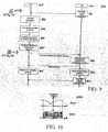
- FIG. 10
- presents two diagrams giving an overview of the adaptive subcarrier loading according to the underlying invention,
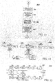
- FIG. 11
- shows a flowchart of a modulation scheme planning,
- FIG. 12
- shows a timing chart according to the underlying invention which is applied to calculate the movement of zero points of the extremely time-variant channel transfer function H(j·ω,t), and
- FIG. 13
- presents a block diagram for a mobile transmission and reception system supporting wireless communication over a multipath propagation channel by means of a pilot-assisted wireless multi-carrier system (here: an OFDM system) comprising means for a channel estimation according to the underlying invention, which can be used for an adaptive subcarrier loading.

- A
- is a complex amplitude factor, derived by transformation of the equation,
- bi(t)
- denotes the complex coefficient of the i-th path, derived by reformation of the equation, and
- Ti(t)
- denotes the position of the i-th zero point point of the channel transfer function G(s,t).

Claims (11)
- A method for an adaptive subcarrier loading for a mobile receiver (1310) in a wireless communication system based on Orthogonal Frequency Division Multiplexing (OFDM) applied to predict the frequency-selective distortion of the channel transfer function for a multipath propagation channel (1320) impaired by attenuation fades and a time-variant behavior when said mobile receiver (1310) is moved, comprising:characterized by the step ofa channel estimation (802), a channel equalization and/or a synchronization on the basis of at least one part of the received signal,an adaptive subcarrier loading (803') technique in which different modulation schemes can be assigned to applied subcarriers (102),
estimating (802) said channel transfer function by evaluating (806) the position and movement of its zero points (A, B, C). - A method according to claim 1,
characterized in that
said zero points (A, B, C) of the estimated channel transfer function are determined by detecting the position of notches on the associated amplitude response of the channel transfer function caused by a frequency-selective fading whose depths are larger than a predefined threshold. - A method according to claim 2,
characterized by
a prediction of said zero points (A, B, C) for succeeding downlink signal bursts (700) by evaluating the movement of said zero points (A, B, C). - A method according to anyone of the preceding claims, wherein the OFDM symbol stream of the associated downlink signal burst (700) is extended by multiplexing one preamble frame (701, 702 and/or 703) each after a predefined number of OFDM data symbols within the associated downlink signal burst.
- A method according to anyone of the preceding claims, wherein channel estimates are steadily exploited during the reception of the OFDM symbol stream by weighting previously obtained channel estimates in order to reduce the effect of noise on the channel estimation.
- A method according to anyone of the previous claims,
characterized in that
reference symbols transmitted by means of said pilot patterns are scrambled by means of a pseudo-noise scrambling sequence generated by a generator polynomial, which is known to the mobile transmitter (1301) and the mobile receiver (1310), in order to randomize the reference symbols to be transmitted. - A method supporting a modulation scheme planning for a mobile transmitter (1301) in a wireless communication system based on Orthogonal Frequency Division Multiplexing (OFDM) in combination with an adaptive subcarrier loading technique which can be applied to predict the frequency-selective distortion of the channel transfer function for a multipath propagation channel (1320) impaired by attenuation fades and a time-variant behavior, in which a mobile receiver (1310) conducts the following steps for each downlink signal burst:performing a first channel estimation (802) by means of a first preamble frame (1202) that serves as a pilot pattern for the current downlink signal burst (1201), and finding (806) zero points (A, B, C) of the estimated channel transfer function by detecting the position of notches on its associated amplitude response characteristic,performing a second channel estimation (802) by means of a second preamble frame (1202) that serves as a pilot pattern for the succeeding downlink signal burst (1203), and finding (806) zero points (A, B, C) of the newly estimated channel transfer function by detecting the position of notches on its associated amplitude response characteristic,estimation (808) and/or prediction (807) of the movement of zero points (A, B, C) of said channel transfer function with the aid of results obtained for the current downlink signal burst (1201) and the succeeding downlink signal burst (1203), andmaking a proposal (803') for the execution of a modulation scheme based on the position and movement of zero points (A, B, C) of the estimated channel transfer function.
- A method supporting a modulation scheme planning for a wireless communication scenario with at least one mobile terminal (405) and at least one access point (401) according to anyone of the preceding claims, in which the following steps are performed in the given order in case the access point (401) transmits (801) a downlink signal to the mobile terminal (405) :first, the mobile terminal (405) receives the downlink signal of the access point (401), estimates (802) the transfer function of the multipath propagation channel (1320), estimates (806) the position of zero points (A), predicts (807) the position of zero points (B, C) for succeeding downlink signal bursts (700), makes a proposal (803') for a modulation scheme according to said prediction, and sends this proposal to the access point (401);then, the access point (401) receives the proposal and evaluates it (804), and - if it is acceptable - sends an acknowledgment message for the proposal, sets up (805) the modulation scheme of the downlink signal according to the proposal, and sends (801) the downlink signal; andfinally, the mobile terminal (405) receives the acknowledgment message for the proposal, sets up (805) a modulation scheme according to the proposal, and receives the downlink signal.
- Software routine running on a mobile receiver (1310) designed for performing a method according to anyone of the preceding claims.
- A mobile receiver supporting wireless communication over a mobile radio channel (1320) by means of Orthogonal Frequency Division Multiplexing (OFDM) systems, comprising:characterized bymeans (1305, 1315) for performing an OFDM multi-carrier modulation and/or an OFDM multi-carrier demodulation,means (1318) for performing a channel estimation (802), a channel equalization and/or a synchronization on the basis of at least one part of the received signal,means (1319) for performing an adaptive subcarrier loading technique (803'), in which different modulation schemes are assigned to the applied subcarriers (102) to increase the capacity usage of the underlying multipath propagation channel (1320),
means (1319, 1321) for predicting a frequency-selective distortion of the channel transfer function for the underlying multipath propagation channel being severely impaired by attenuation fades and a time-variant behavior when the mobile receiver (1310) is moved, which calculate an estimation (802) of said channel transfer function by evaluating (806) the position of its zero points (A, B, C). - A mobile telecommunications device,
characterized by
a mobile receiver (1310) according to claim 10 designed for supporting a method according to anyone of the claims 1 to 8.Depicted Features and their Corresponding Reference Signs No. Feature 100 diagram showing the spectrum of an OFDM symbol 101 and the modulation schemes for its subcarriers 102 101 OFDM symbol consisting of 52 subcarriers 102 subcarriers of said OFDM symbol 101 200 four diagrams 201, 202, 203, and 204 showing the modulation schemes that can be applied to each subcarrier 201 1st modulation scheme: Binary Phase Shift Keying (BPSK) 202 2nd modulation scheme: Quaternary Phase Shift Keying with a phase shift of ϕk = k·π/4 for k ∈ {1,3,5,7} (π/4-QPSK) 203 3rd modulation scheme: Quadrature Amplitude Modulation for a 16-point signal constellation (16-QAM) 204 4th modulation scheme: Quadrature Amplitude Modulation for a 64-point signal constellation (64-QAM) 300 block diagram for a mobile transmission and reception system supporting wireless communication over a multipath propagation channel 320 by means of a pilot-assisted wireless multi-carrier system (here: an OFDM system) comprising means for a channel estimation 318 according to the state of the art 301 OFDM transmitter 303 channel encoder 304 serial-to-parallel (S/P) converter 305 OFDM modulator 306 digital signal processor performing an Inverse Fast Fourier Transform (IFFT) 307 digital-to-analog (D/A) converter 308 RF block performing a signal up-conversion from the base-band to the passband 309 transmitting (TX) antenna 310 OFDM receiver 311 receiving (RX) antenna 312 RF block performing a signal down-conversion from the pass-band to the baseband 313 analog-to-digital (A/D) converter 314 digital signal processor performing a Fast Fourier Transform (FFT) 315 OFDM demodulator 316 parallel-to-serial (P/S) converter 317 channel decoder 318 channel estimator 320 multipath propagation channel, characterized by a severe frequency-selective fading and a time-variant behavior 400 diagram showing a typical example for a propagation model 401 access point (AP) 402 RX/TX antenna of said access point 401 403 1st path of the radiated RF signal from the transmitter to the receiver, characterized by reflection at buildings and other objects 404 2nd path of the radiated RF signal from the transmitter to the receiver, characterized by reflection at buildings and other objects 405 mobile terminal (MT) in a moving receiver (e.g. a car which drives at high speed) 406 receiving (RX) antenna of said mobile terminal (MT) 500 five diagrams giving an overview of channel distortion caused by a severe frequency-selective fading and the time-variant behavior of the underlying multipath propagation channel 320 501 diagram showing the movement of zero points (A, B, and C) of the channel transfer function H(s,t) on an s-plane, where s is the complex observation frequency (s = σ + j·ω) 502 diagram showing the amplitude response |H(j·ω,t)| of the channel transfer function H(j·ω,t) according to the current position of its notches (A, B, and C) 503 diagram showing a conventional spectrum of an OFDM signal, in which each subcarrier is modulated by a fixed modulation scheme (202, 203, or 204) 504 diagram showing a first spectrum of a transmitted OFDM signal between the positions of the zero points A and B according to the underlying invention 505 diagram showing a second spectrum of a transmitted OFDM signal between the positions of the zero points B and C according to the underlying invention 600 block diagram for a mobile transmission and reception system supporting wireless communication over a multipath propagation channel 620 by means of a pilot-assisted wireless multi-carrier system (here: an OFDM system) comprising means for a channel estimation 618, which can be used for an adaptive subcarrier loading 601 OFDM transmitter 603 channel encoder 604 serial-to-parallel (S/P) converter 605 OFDM modulator 606 digital signal processor performing an Inverse Fast Fourier Transform (IFFT) 607 digital-to-analog (D/A) converter 608 radio frequency (RF) block 609 transmitting (TX) antenna 610 OFDM receiver 611 receiving (RX) antenna 612 radio frequency (RF) block 613 analog-to-digital (A/D) converter 614 digital signal processor performing a Fast Fourier Transform (FFT) 615 OFDM demodulator 616 parallel-to-serial (P/S) converter 617 channel decoder 618 channel estimator 619 central processing unit (CPU) 620 multipath propagation channel, characterized by a severe frequency-selective fading and a time-variant behavior 700 example of a downlink signal burst with three preambles (A, B, and C) according to the HiperLAN/2 standard 701 1st preamble frame (A) of the downlink signal burst 700 702 2nd preamble frame (B) of the downlink signal burst 700 703 3rd preamble frame (C) of the downlink signal burst 700 704 data frame of the downlink signal burst 700 800 sequence chart showing the data transfer between the access point 401 (AP) and the mobile terminal 405 (MT) according to the state of the art 801 downlink signal transmission 802 channel estimation 803 proposal for the execution of a modulation scheme according to the state of the art 803' proposal for the execution of a modulation scheme using the position and movement of zero points of the channel transfer function H(j·ω,t) according to the underlying invention 804 evaluation of the proposal 803 for the execution of a modulation scheme 805 set-up of a modulation scheme 806 estimation of the position of zero points of the channel transfer function H(j·ω,t) 807 prediction of the position of said zero points for the preamble C of next downlink signal burst j 808 estimation of the movement of zero points of the channel transfer function H(j·ω,t) using the results of the current downlink signal burst j-1 and the next downlink signal burst j 900 sequence chart showing the data transfer between the access point 401 (AP) and the mobile terminal 405 (MT) according to the underlying invention 1000 two diagrams giving an overview of the adaptive subcarrier loading according to the underlying invention 1001 diagram showing the amplitude response |H(j·ω, t)| of the channel transfer function H(j·ω,t) 1002 diagram showing the spectrum of a transmitted OFDM signal and the modulation schemes of its subcarriers 102 1100 flowchart of a modulation scheme planning 1200 timing chart according to the underlying invention which is applied to calculate the movement of zero points of the channel transfer function H(j·ω,t) 1201 downlink signal burst j-1 with the preambles A, B, and C 1202 preamble C of the (j-1)-th downlink signal burst 1201 1203 downlink signal burst j with the preambles A, B, and C 1204 preamble C of the j-th downlink signal burst 1203 1205 unit applied to calculate the movement of zero points of the channel transfer function H(j·ω,t) 1206 1st unit applied to estimate the position of zero points of the channel transfer function H(j·ω,t) based on the preamble C of the (j-1)-th downlink signal burst 1201 1207 2nd unit applied to estimate the position of zero points of the channel transfer function H(j·ω,t) based on the preamble C of the j-th downlink signal burst 1203 1208 downlink signal burst j+1 with the preambles A, B, and C 1300 block diagram for a mobile transmission and reception sys- tem supporting wireless communication over a multipath propagation channel 1320 by means of a pilot-assisted wireless multi-carrier system (here: an OFDM system) comprising means for a channel estimation 1318 according to the underlying invention, which can be used for an adaptive subcarrier loading 1301 OFDM transmitter 1303 channel encoder 1304 serial-to-parallel (S/P) converter 1305 OFDM modulator 1306 digital signal processor performing an Inverse Fast Fourier Transform (IFFT) 1307 digital-to-analog (D/A) converter 1308 radio frequency (RF) block 1309 transmitting (TX) antenna 1310 OFDM receiver 1311 receiving (RX) antenna 1312 radio frequency (RF) block 1313 analog-to-digital (A/D) converter 1314 digital signal processor performing a Fast Fourier Transform (FFT) 1315 OFDM demodulator 1316 parallel-to-serial (P/S) converter 1317 channel decoder 1318 channel estimator 1319 central processing unit (CPU) 1320 multipath propagation channel, characterized by a severe frequency-selective fading and a time-variant behavior 1321 zero estimator A position of the i-th zero point Ti,j -1 of the channel transfer function H(s,t) on an s-plane obtained for the (j-1)-th downlink signal burst, which corresponds to a certain notch on the amplitude response |H(j·ω,t)| of the channel transfer function H(j·ω,t) at the discrete time j-1 B position of the i-th zero point Ti,j of the channel transfer function H(s,t) on an s-plane obtained for the j-th downlink signal burst, which corresponds to a certain notch on the amplitude response |H(j·ω,t)| of the channel transfer function H(j·ω,t) at the discrete time j C position of the i-th zero point Ti,j +1 of the channel transfer function H(s,t) on an s-plane obtained for the (j+1)-th downlink signal burst, which corresponds to a certain notch on the amplitude response |H(j·ω,t)| of the channel transfer function H(j·ω,t) at the discrete time j+1
Priority Applications (4)
| Application Number | Priority Date | Filing Date | Title |
|---|---|---|---|
| DE60206356T DE60206356T2 (en) | 2002-04-16 | 2002-04-16 | Orthogonal frequency division multiplexing (OFDM) with channel prediction |
| EP02008586A EP1355467B8 (en) | 2002-04-16 | 2002-04-16 | Orthogonal frequency division multiplexing (OFDM) system with channel transfer function prediction |
| US10/413,687 US7386072B2 (en) | 2002-04-16 | 2003-04-15 | Orthogonal frequency division multiplexing (OFDM) system with channel transfer function prediction |
| JP2003112209A JP2003333013A (en) | 2002-04-16 | 2003-04-16 | Orthogonal frequency division multiplexing system with channel transfer function prediction |
Applications Claiming Priority (1)
| Application Number | Priority Date | Filing Date | Title |
|---|---|---|---|
| EP02008586A EP1355467B8 (en) | 2002-04-16 | 2002-04-16 | Orthogonal frequency division multiplexing (OFDM) system with channel transfer function prediction |
Publications (3)
| Publication Number | Publication Date |
|---|---|
| EP1355467A1 true EP1355467A1 (en) | 2003-10-22 |
| EP1355467B1 EP1355467B1 (en) | 2005-09-28 |
| EP1355467B8 EP1355467B8 (en) | 2005-12-07 |
Family
ID=28459476
Family Applications (1)
| Application Number | Title | Priority Date | Filing Date |
|---|---|---|---|
| EP02008586A Expired - Lifetime EP1355467B8 (en) | 2002-04-16 | 2002-04-16 | Orthogonal frequency division multiplexing (OFDM) system with channel transfer function prediction |
Country Status (4)
| Country | Link |
|---|---|
| US (1) | US7386072B2 (en) |
| EP (1) | EP1355467B8 (en) |
| JP (1) | JP2003333013A (en) |
| DE (1) | DE60206356T2 (en) |
Cited By (7)
| Publication number | Priority date | Publication date | Assignee | Title |
|---|---|---|---|---|
| GB2446849A (en) * | 2007-02-21 | 2008-08-27 | Toshiba Res Europ Ltd | Interference detection and avoidance signalling and processing |
| DE102008015460A1 (en) * | 2008-03-18 | 2009-09-24 | Volkswagen Ag | Method for communication between vehicle and e.g. access point, in wireless local area network, involves adjusting sending frequency of vehicle for producing wireless connection with stationary node based on Doppler-movement |
| US7680218B2 (en) | 2005-10-25 | 2010-03-16 | Telefonaktiebolaget Lm Ericsson (Publ) | Method and apparatus for communication channel estimation |
| CN101594224B (en) * | 2008-05-29 | 2013-07-17 | 索尼株式会社 | Transmission device and method for transmitting signal in multi-carrier systems |
| TWI406542B (en) * | 2005-11-14 | 2013-08-21 | Ibiquity Digital Corp | Equalizer for am in-band on-channel radio receivers |
| KR101354642B1 (en) * | 2005-12-30 | 2014-01-21 | 오렌지 | Method and device for dynamically selecting orthogonal functions of an orthogonal transmission system |
| US11381442B2 (en) * | 2020-04-03 | 2022-07-05 | Wuhan University | Time domain channel prediction method and time domain channel prediction system for OFDM wireless communication system |
Families Citing this family (51)
| Publication number | Priority date | Publication date | Assignee | Title |
|---|---|---|---|---|
| US7903538B2 (en) * | 2003-08-06 | 2011-03-08 | Intel Corporation | Technique to select transmission parameters |
| CN102932125B (en) | 2003-08-20 | 2016-01-13 | 松下电器(美国)知识产权公司 | Base station apparatus and the method for reseptance for base station apparatus |
| JP3961999B2 (en) * | 2003-09-22 | 2007-08-22 | 株式会社東芝 | Multi-carrier transmission system, multi-carrier receiver, and transmitter |
| JP4043442B2 (en) * | 2004-01-09 | 2008-02-06 | 株式会社東芝 | Wireless transmission device, wireless reception device, wireless transmission method, wireless reception method, and wireless communication system |
| DE102004002145B4 (en) * | 2004-01-15 | 2007-11-22 | Radioplan Gmbh | Method and device for adapting a radio network model to the conditions of a real radio network |
| CA2558240A1 (en) * | 2004-03-05 | 2005-09-22 | Nextnet Wireless, Inc. | System and method for adaptive modulation |
| KR100620914B1 (en) * | 2004-04-07 | 2006-09-13 | 삼성전자주식회사 | Apparatus and method for switching between MC mode and diversity mode in broadband wireless communication system |
| JP3841100B2 (en) * | 2004-07-06 | 2006-11-01 | セイコーエプソン株式会社 | Electronic device and wireless communication terminal |
| WO2006035373A1 (en) * | 2004-09-29 | 2006-04-06 | Koninklijke Philips Electronics N.V. | Harmonic generation of a fundamental frequency system and method |
| KR100606083B1 (en) * | 2004-11-04 | 2006-07-31 | 삼성전자주식회사 | Subchannel Allocation System and Method in Broadband Wireless Access Communication System |
| US7649861B2 (en) * | 2004-11-30 | 2010-01-19 | Intel Corporation | Multiple antenna multicarrier communication system and method with reduced mobile-station processing |
| US7822128B2 (en) | 2004-12-03 | 2010-10-26 | Intel Corporation | Multiple antenna multicarrier transmitter and method for adaptive beamforming with transmit-power normalization |
| FR2880219B1 (en) * | 2004-12-23 | 2007-02-23 | Thales Sa | METHOD AND SYSTEM FOR DIGITAL RADIOCOMMUNICATION, IN PARTICULAR FOR MOBILE SOIL STATIONS |
| JP4746420B2 (en) * | 2004-12-27 | 2011-08-10 | 株式会社東芝 | Wireless communication apparatus and method |
| US8666387B2 (en) * | 2004-12-30 | 2014-03-04 | Samsung Electronics Co., Ltd. | Apparatus and method for determining transmit signal parameters using real-time channel measurements |
| US7660368B2 (en) * | 2005-01-11 | 2010-02-09 | Qualcomm Incorporated | Bit log likelihood ratio evaluation |
| CN101945080B (en) * | 2005-01-11 | 2012-11-14 | 高通股份有限公司 | Method and apparatus for decoding data in a layered modulation system |
| EP1841113A4 (en) * | 2005-01-11 | 2013-02-20 | Sharp Kk | ADAPTIVE MODULATION CONTROL DEVICE AND RADIO COMMUNICATION DEVICE |
| KR100914877B1 (en) * | 2005-01-11 | 2009-08-31 | 퀄컴 인코포레이티드 | Methods and apparatus for transmitting layered and non-layered data via layered modulation |
| US7522555B2 (en) | 2005-01-21 | 2009-04-21 | Intel Corporation | Techniques to manage channel prediction |
| US20060198454A1 (en) * | 2005-03-02 | 2006-09-07 | Qualcomm Incorporated | Adaptive channel estimation thresholds in a layered modulation system |
| US8422437B2 (en) * | 2005-03-31 | 2013-04-16 | Nec Corporation | Resource assignment method for communication system adapted for change of channel |
| US7602855B2 (en) * | 2005-04-01 | 2009-10-13 | Interdigital Technology Corporation | Method and apparatus for singular value decomposition of a channel matrix |
| CN101199148B (en) * | 2005-06-15 | 2012-04-04 | 华为技术有限公司 | A method of generating two-dimensional pilot pattern |
| US7773703B2 (en) * | 2005-07-08 | 2010-08-10 | Qualcomm Incorporated | Methods and apparatus for communicating using a DC tone |
| US7773679B2 (en) * | 2005-07-08 | 2010-08-10 | Qualcomm Incorporated | Base station methods and apparatus for DC tone special treatment |
| US8213978B1 (en) * | 2005-08-29 | 2012-07-03 | At&T Mobility Ii Llc | Estimating mobile local propagation environment characteristics for wireless communications |
| EP1958410B1 (en) * | 2005-12-02 | 2015-03-25 | Nxp B.V. | Ofdm cognitive radio with zero overhead signalling of deleted subcarriers frequencies |
| KR20070061215A (en) * | 2005-12-08 | 2007-06-13 | 한국전자통신연구원 | Transmission and reception device of wideband wireless channel measurement device using multiple carriers |
| US7793195B1 (en) * | 2006-05-11 | 2010-09-07 | Link—A—Media Devices Corporation | Incremental generation of polynomials for decoding reed-solomon codes |
| AU2007252224B2 (en) * | 2006-05-24 | 2011-10-06 | Cohda Wireless Pty Ltd | Method and apparatus for multicarrier communications |
| US7881403B2 (en) * | 2006-10-10 | 2011-02-01 | Futurewei Technologies, Inc. | System for realizing emergency rate adjustment |
| US8171368B1 (en) | 2007-02-16 | 2012-05-01 | Link—A—Media Devices Corporation | Probabilistic transition rule for two-level decoding of reed-solomon codes |
| EP1971043A1 (en) | 2007-03-16 | 2008-09-17 | Sony Deutschland GmbH | Transmitting device and method for transmitting signals in a wireless communication system, receiving device and method for receiving signals in a wireless communication system |
| US8190092B1 (en) | 2007-08-29 | 2012-05-29 | Marvell International Ltd. | Selecting modulation and coding scheme in the presence of interference |
| TWI355175B (en) * | 2007-05-31 | 2011-12-21 | Ind Tech Res Inst | Multicarrier transmitting system and method thereo |
| CN101796755A (en) * | 2007-08-28 | 2010-08-04 | 夏普株式会社 | communication device |
| KR100930718B1 (en) * | 2007-10-26 | 2009-12-09 | 한국전자통신연구원 | Method and apparatus for transmitting broadcast signal, recording medium and receiving apparatus |
| JP4482834B2 (en) * | 2008-03-13 | 2010-06-16 | ソニー株式会社 | Modulation apparatus and method, demodulation apparatus and method, program, and recording medium |
| JP5215704B2 (en) * | 2008-03-26 | 2013-06-19 | パナソニック株式会社 | Adaptive demodulation method |
| CN102282818B (en) | 2009-01-22 | 2014-06-18 | Lg电子株式会社 | Apparatus for transmitting and receiving a signal and method of transmitting and receiving a signal |
| EP2801156B1 (en) * | 2012-01-05 | 2015-11-25 | Telefonaktiebolaget LM Ericsson (PUBL) | A multi-carrier method in a measurement device |
| US9100278B2 (en) | 2012-08-17 | 2015-08-04 | Qualcomm Incorporated | OFDM speed estimation |
| WO2014032908A2 (en) * | 2012-08-29 | 2014-03-06 | Telefonica, S.A | A method for reducing signaling messages and handovers in wireless networks |
| US9634795B2 (en) | 2013-03-04 | 2017-04-25 | Intel Corporation | Configurable constellation mapping to control spectral efficiency versus signal-to-noise ratio |
| CN105814856B (en) * | 2013-11-26 | 2019-02-12 | 普鲁斯恩公司 | Method, apparatus and system for controlling combined waveforms, apparatus for combining multiple signals |
| US10135562B2 (en) * | 2015-05-28 | 2018-11-20 | Huawei Technologies Co., Ltd. | Apparatus and method for link adaptation in uplink grant-less random access |
| US10277334B2 (en) * | 2016-11-03 | 2019-04-30 | Khalifa University of Science and Technology | Hybrid OFDM body coupled communication transceiver |
| EP3725017A1 (en) * | 2017-12-13 | 2020-10-21 | Telefonaktiebolaget LM Ericsson (publ) | Method of estimating a propagation delay difference of an optical link and apparatus for same |
| CN110995379B (en) * | 2019-12-06 | 2021-03-30 | 武汉大学 | A channel prediction system and method for OFDM wireless communication system |
| CN118944791B (en) * | 2024-08-12 | 2026-03-10 | 北京邮电大学 | Channel prediction method, device and program based on wireless environment information |
Citations (1)
| Publication number | Priority date | Publication date | Assignee | Title |
|---|---|---|---|---|
| WO2001008369A1 (en) * | 1999-07-26 | 2001-02-01 | University Of Southampton | Adaptive ofdm transmitter |
Family Cites Families (2)
| Publication number | Priority date | Publication date | Assignee | Title |
|---|---|---|---|---|
| US5479447A (en) * | 1993-05-03 | 1995-12-26 | The Board Of Trustees Of The Leland Stanford, Junior University | Method and apparatus for adaptive, variable bandwidth, high-speed data transmission of a multicarrier signal over digital subscriber lines |
| US20030193889A1 (en) * | 2002-04-11 | 2003-10-16 | Intel Corporation | Wireless device and method for interference and channel adaptation in an OFDM communication system |
-
2002
- 2002-04-16 EP EP02008586A patent/EP1355467B8/en not_active Expired - Lifetime
- 2002-04-16 DE DE60206356T patent/DE60206356T2/en not_active Expired - Lifetime
-
2003
- 2003-04-15 US US10/413,687 patent/US7386072B2/en not_active Expired - Lifetime
- 2003-04-16 JP JP2003112209A patent/JP2003333013A/en not_active Withdrawn
Patent Citations (1)
| Publication number | Priority date | Publication date | Assignee | Title |
|---|---|---|---|---|
| WO2001008369A1 (en) * | 1999-07-26 | 2001-02-01 | University Of Southampton | Adaptive ofdm transmitter |
Non-Patent Citations (4)
| Title |
|---|
| EYCEOZ T ET AL: "DETERMINISTIC CHANNEL MODELING AND LONG RANGE PREDICTION OF FAST FADING MOBILE RADIO CHANNELS", IEEE COMMUNICATIONS LETTERS, IEEE SERVICE CENTER, PISCATAWAY,US, US, vol. 2, no. 9, 1 September 1998 (1998-09-01), pages 254 - 256, XP000784809, ISSN: 1089-7798 * |
| MUNSTER M ET AL: "Co-channel interference suppression assisted adaptive OFDM in interference limited environments", VTC 1999-FALL. IEEE VTS 50TH. VEHICULAR TECHNOLOGY CONFERENCE. GATEWAY TO THE 21ST. CENTURY COMMUNICATIONS VILLAGE. AMSTERDAM, SEPT. 19 - 22, 1999, IEEE VEHICULAR TECHNOLGY CONFERENCE, NEW YORK, NY: IEEE, US, vol. 1 CONF. 50, 19 September 1999 (1999-09-19), pages 284 - 288, XP002143788, ISBN: 0-7803-5436-2 * |
| SOURYAL, M.R.; PICKHOLTZ, R.L.: "Adaptive modulation with imperfect channel information in OFDM", COMMUNICATIONS, 2001. ICC 2001. IEEE INTERNATIONAL CONFERENCE ON, vol. 6, 11 June 2001 (2001-06-11) - 14 June 2001 (2001-06-14), Helsinki, Finland, pages 1861 - 1865, XP002213933 * |
| THOEN S ET AL: "PREDICTIVE ADAPTIVE LOADING FOR HIPERLAN II", VTC 2000-FALL. IEEE VTS 52ND. VEHICULAR TECHNOLOGY CONFERENCE. BOSTON, MA, SEPT. 24 - 28, 2000, IEEE VEHICULAR TECHNOLGY CONFERENCE, NEW YORK, NY: IEEE, US, vol. 5 OF 6. CONF. 52, 24 September 2000 (2000-09-24), pages 2166 - 2172, XP000988402, ISBN: 0-7803-6508-9 * |
Cited By (9)
| Publication number | Priority date | Publication date | Assignee | Title |
|---|---|---|---|---|
| US7680218B2 (en) | 2005-10-25 | 2010-03-16 | Telefonaktiebolaget Lm Ericsson (Publ) | Method and apparatus for communication channel estimation |
| TWI406542B (en) * | 2005-11-14 | 2013-08-21 | Ibiquity Digital Corp | Equalizer for am in-band on-channel radio receivers |
| KR101354642B1 (en) * | 2005-12-30 | 2014-01-21 | 오렌지 | Method and device for dynamically selecting orthogonal functions of an orthogonal transmission system |
| GB2446849A (en) * | 2007-02-21 | 2008-08-27 | Toshiba Res Europ Ltd | Interference detection and avoidance signalling and processing |
| GB2446849B (en) * | 2007-02-21 | 2008-12-31 | Toshiba Res Europ Ltd | Interference detection and avoidance signalling and processing |
| DE102008015460A1 (en) * | 2008-03-18 | 2009-09-24 | Volkswagen Ag | Method for communication between vehicle and e.g. access point, in wireless local area network, involves adjusting sending frequency of vehicle for producing wireless connection with stationary node based on Doppler-movement |
| DE102008015460B4 (en) * | 2008-03-18 | 2016-11-17 | Volkswagen Ag | Method and apparatus for communication in a Car2X radio network |
| CN101594224B (en) * | 2008-05-29 | 2013-07-17 | 索尼株式会社 | Transmission device and method for transmitting signal in multi-carrier systems |
| US11381442B2 (en) * | 2020-04-03 | 2022-07-05 | Wuhan University | Time domain channel prediction method and time domain channel prediction system for OFDM wireless communication system |
Also Published As
| Publication number | Publication date |
|---|---|
| DE60206356D1 (en) | 2005-11-03 |
| DE60206356T2 (en) | 2006-05-11 |
| EP1355467B8 (en) | 2005-12-07 |
| US20030232601A1 (en) | 2003-12-18 |
| US7386072B2 (en) | 2008-06-10 |
| EP1355467B1 (en) | 2005-09-28 |
| JP2003333013A (en) | 2003-11-21 |
Similar Documents
| Publication | Publication Date | Title |
|---|---|---|
| EP1355467B1 (en) | Orthogonal frequency division multiplexing (OFDM) system with channel transfer function prediction | |
| US8605841B2 (en) | Method for processing received OFDM data symbols and OFDM baseband receiver | |
| US10965389B2 (en) | OFDM system with reverse link interference estimation | |
| Zhang et al. | A novel OFDM transmission scheme with length-adaptive cyclic prefix | |
| US8077627B2 (en) | Receiving apparatus and method in broadband wireless access system | |
| CN101932090B (en) | System and method for intelligent transmitted power control scheme | |
| JP3455073B2 (en) | Multicarrier signal detection and parameter estimation method in mobile radio communication channel | |
| KR20050084884A (en) | Uplink pilot and signaling transmission in wireless communication systems | |
| US7228113B1 (en) | SIMO/MISO transceiver for providing packet data communication with SISO transceiver | |
| EP1294148A1 (en) | Delay spread estimation of multipath fading channels in a OFDM receiver | |
| Muneta et al. | A new frequency-domain link adaptation scheme for broadband OFDM systems | |
| Lim et al. | Novel OFDM transmission scheme to overcome caused by multipath delay longer than cyclic prefix | |
| Gibbard et al. | Asymmetric signal processing for indoor wireless LANs | |
| Das et al. | Variable guard interval orthogonal frequency division multiplexing in presence of carrier frequency offset | |
| Omar et al. | Adaptive channel characterization for wireless communication | |
| Das et al. | Variable guard interval orthogonal frequency division multiplexing in dynamic channel condition | |
| Lai et al. | An adaptive OFDM system with variable guard interval | |
| Cheng et al. | Subspace-MMSE blind channel estimation for multiuser OFDM with receiver diversity | |
| Shibakura et al. | ASB-AM/OFDMA with FSS and TPC for Reducing Packet Overhead | |
| Uesugi | An interference cancellation scheme for OFDM using adaptive algorithm | |
| Miyazaki et al. | A Study on forward link capacity in MC-CDMA cellular system with MMSEC receiver | |
| Jain et al. | Engineering Universe for scientific Research and management | |
| Abe et al. | Frequency-domain pre-equalization for MC-CDMA/TDD uplink and its bit error rate analysis | |
| Athanasios et al. | SNR estimation in frequency selective Rayleigh channel for HIPERLAN/2 transceiver | |
| Takei et al. | Uplink Pre-Equalization Using MMSE Prediction for TDDIMC-CDMA Systems |
Legal Events
| Date | Code | Title | Description |
|---|---|---|---|
| PUAI | Public reference made under article 153(3) epc to a published international application that has entered the european phase |
Free format text: ORIGINAL CODE: 0009012 |
|
| AK | Designated contracting states |
Kind code of ref document: A1 Designated state(s): AT BE CH CY DE DK ES FI FR GB GR IE IT LI LU MC NL PT SE TR |
|
| AX | Request for extension of the european patent |
Extension state: AL LT LV MK RO SI |
|
| 17P | Request for examination filed |
Effective date: 20040422 |
|
| AKX | Designation fees paid |
Designated state(s): DE FR GB |
|
| 17Q | First examination report despatched |
Effective date: 20040618 |
|
| GRAP | Despatch of communication of intention to grant a patent |
Free format text: ORIGINAL CODE: EPIDOSNIGR1 |
|
| GRAS | Grant fee paid |
Free format text: ORIGINAL CODE: EPIDOSNIGR3 |
|
| GRAA | (expected) grant |
Free format text: ORIGINAL CODE: 0009210 |
|
| AK | Designated contracting states |
Kind code of ref document: B1 Designated state(s): DE FR GB |
|
| REG | Reference to a national code |
Ref country code: GB Ref legal event code: FG4D |
|
| RAP2 | Party data changed (patent owner data changed or rights of a patent transferred) |
Owner name: SONY DEUTSCHLAND GMBH |
|
| REF | Corresponds to: |
Ref document number: 60206356 Country of ref document: DE Date of ref document: 20051103 Kind code of ref document: P |
|
| RAP2 | Party data changed (patent owner data changed or rights of a patent transferred) |
Owner name: SONY DEUTSCHLAND GMBH |
|
| RAP2 | Party data changed (patent owner data changed or rights of a patent transferred) |
Owner name: SONY DEUTSCHLAND GMBH |
|
| ET | Fr: translation filed | ||
| PLBE | No opposition filed within time limit |
Free format text: ORIGINAL CODE: 0009261 |
|
| STAA | Information on the status of an ep patent application or granted ep patent |
Free format text: STATUS: NO OPPOSITION FILED WITHIN TIME LIMIT |
|
| 26N | No opposition filed |
Effective date: 20060629 |
|
| PGFP | Annual fee paid to national office [announced via postgrant information from national office to epo] |
Ref country code: FR Payment date: 20110510 Year of fee payment: 10 |
|
| REG | Reference to a national code |
Ref country code: FR Ref legal event code: ST Effective date: 20121228 |
|
| PG25 | Lapsed in a contracting state [announced via postgrant information from national office to epo] |
Ref country code: FR Free format text: LAPSE BECAUSE OF NON-PAYMENT OF DUE FEES Effective date: 20120430 |
|
| PGFP | Annual fee paid to national office [announced via postgrant information from national office to epo] |
Ref country code: GB Payment date: 20140422 Year of fee payment: 13 |
|
| GBPC | Gb: european patent ceased through non-payment of renewal fee |
Effective date: 20150416 |
|
| PG25 | Lapsed in a contracting state [announced via postgrant information from national office to epo] |
Ref country code: GB Free format text: LAPSE BECAUSE OF NON-PAYMENT OF DUE FEES Effective date: 20150416 |
|
| REG | Reference to a national code |
Ref country code: DE Ref legal event code: R082 Ref document number: 60206356 Country of ref document: DE Representative=s name: MITSCHERLICH, PATENT- UND RECHTSANWAELTE PARTM, DE Ref country code: DE Ref legal event code: R081 Ref document number: 60206356 Country of ref document: DE Owner name: SONY DEUTSCHLAND GMBH, DE Free format text: FORMER OWNER: SONY INTERNATIONAL (EUROPE) GMBH, 10785 BERLIN, DE |
|
| REG | Reference to a national code |
Ref country code: DE Ref legal event code: R084 Ref document number: 60206356 Country of ref document: DE |
|
| PGFP | Annual fee paid to national office [announced via postgrant information from national office to epo] |
Ref country code: DE Payment date: 20210323 Year of fee payment: 20 |
|
| REG | Reference to a national code |
Ref country code: DE Ref legal event code: R071 Ref document number: 60206356 Country of ref document: DE |