EP1355375A1 - Dual antenna - Google Patents
Dual antenna Download PDFInfo
- Publication number
- EP1355375A1 EP1355375A1 EP03252231A EP03252231A EP1355375A1 EP 1355375 A1 EP1355375 A1 EP 1355375A1 EP 03252231 A EP03252231 A EP 03252231A EP 03252231 A EP03252231 A EP 03252231A EP 1355375 A1 EP1355375 A1 EP 1355375A1
- Authority
- EP
- European Patent Office
- Prior art keywords
- antenna
- rod
- patch
- electromagnetic wave
- short axis
- Prior art date
- Legal status (The legal status is an assumption and is not a legal conclusion. Google has not performed a legal analysis and makes no representation as to the accuracy of the status listed.)
- Withdrawn
Links
- 230000009977 dual effect Effects 0.000 title claims description 26
- 239000000758 substrate Substances 0.000 claims description 6
- 230000010287 polarization Effects 0.000 abstract description 8
- 230000005855 radiation Effects 0.000 description 6
- 239000002131 composite material Substances 0.000 description 2
- 230000005284 excitation Effects 0.000 description 2
- 230000002411 adverse Effects 0.000 description 1
- 230000000694 effects Effects 0.000 description 1
- 238000004806 packaging method and process Methods 0.000 description 1
- 229920006395 saturated elastomer Polymers 0.000 description 1
Images

Classifications
-
- H—ELECTRICITY
- H01—ELECTRIC ELEMENTS
- H01Q—ANTENNAS, i.e. RADIO AERIALS
- H01Q9/00—Electrically-short antennas having dimensions not more than twice the operating wavelength and consisting of conductive active radiating elements
- H01Q9/04—Resonant antennas
- H01Q9/0407—Substantially flat resonant element parallel to ground plane, e.g. patch antenna
- H01Q9/0428—Substantially flat resonant element parallel to ground plane, e.g. patch antenna radiating a circular polarised wave
-
- H—ELECTRICITY
- H01—ELECTRIC ELEMENTS
- H01Q—ANTENNAS, i.e. RADIO AERIALS
- H01Q1/00—Details of, or arrangements associated with, antennas
- H01Q1/12—Supports; Mounting means
-
- H—ELECTRICITY
- H01—ELECTRIC ELEMENTS
- H01Q—ANTENNAS, i.e. RADIO AERIALS
- H01Q1/00—Details of, or arrangements associated with, antennas
- H01Q1/27—Adaptation for use in or on movable bodies
- H01Q1/32—Adaptation for use in or on road or rail vehicles
- H01Q1/325—Adaptation for use in or on road or rail vehicles characterised by the location of the antenna on the vehicle
- H01Q1/3275—Adaptation for use in or on road or rail vehicles characterised by the location of the antenna on the vehicle mounted on a horizontal surface of the vehicle, e.g. on roof, hood, trunk
-
- H—ELECTRICITY
- H01—ELECTRIC ELEMENTS
- H01Q—ANTENNAS, i.e. RADIO AERIALS
- H01Q21/00—Antenna arrays or systems
- H01Q21/28—Combinations of substantially independent non-interacting antenna units or systems
Definitions
- the present invention relates to a dual antenna unitized by installing in parallel a patch antenna capable of transmitting and receiving a circularly polarized electromagnetic wave to and from a Global Positioning System (GPS) satellite or the like and a rod-shaped antenna capable of transmitting and receiving a linearly polarized electromagnetic wave for use in mobile telephony or the like.
- GPS Global Positioning System
- Vehicle-mountable patch antennas have been known since years ago as means for finding one' s current geographical position by receiving an electromagnetic wave from a GPS satellite, and more recently vehicle-mountable dual antennas, each combining a rod-shaped antenna for mobile telephone use with a patch antenna for GPS use, have become available for practical use.
- a dual antenna has a common radome compactly housing a patch antenna and a rod-shaped antenna. As it can be handled as a relatively small antenna unit combining the function to receive a circularly polarized electromagnetic wave from a GPS satellite and a function to receive a linearly polarized electromagnetic wave for use in mobile telephony, the dual antenna is expected to find use in many different areas along with the development and expansion of information and communication services.
- Fig. 4 shows a plan of such a dual antenna according to the prior art, in which the illustration of its radome is dispensed with.
- a patch antenna 3 and a rod-shaped antenna 4 are provided in parallel on a base plate 2, and these two antennas 3 and 4 receive power supply via cables 5 and 6 and connectors (not shown).
- the patch antenna 3 is fabricated by providing a power feed patch 7, which is a radiation element of a microstrip structure, over a dielectric substrate 8, mounting this dielectric substrate 8 on a circuit board 9, and packaging components of a low-noise amplifier circuit (not shown; including an amplifier and a band pass filter), covered by a shield case, on the bottom side of the circuit board 9.
- a power feed patch 7 which is a radiation element of a microstrip structure
- a short axis 7a having a smaller resonance length matching a higher resonance frequency (f1) mode and a long axis 7b having a greater resonance length matching a lower resonance frequency (f2) mode are defined by providing degenerate separating elements such as notches or projections, and the short axis 7a and the long axis 7b orthogonally cross each other. Excitation at a frequency between these high and low resonance frequencies f1 and f2 to generate a 90-degree phase difference between the radiation fields in the two modes can make the composite radiation field a circular polarization. This enables a circularly polarized electromagnetic wave of 1.575 GHz transmitted from a GPS satellite to be received by the patch antenna 3.
- the rod-shaped antenna 4 is fixed to a circuit board 11 adjoining the patch antenna 3, and erected in a slightly inclined state.
- This rod-shaped antenna 4 can transmit and receive electromagnetic waves of the 850 MHz band and the 1.85 GHz band used for mobile telephony, and is connected to a transmitter/receiver (not shown) via the cable 6 and the like.
- the radome (not shown) is formed in such a shape as covers the patch antenna 3 and the rod-shaped antenna 4 and fixed to the base plate 2.
- An object of the present invention attempted in view of this problem with the prior art, is to provide a highly reliable dual antenna made less susceptible to the adverse effect of the electromagnetic wave radiating from its rod-shaped antenna on an adjoining patch antenna.
- a dual antenna according to the invention is provided with a patch antenna having a power feed patch disposed over a dielectric substrate and capable of transmitting and receiving a circularly polarized electromagnetic wave and a rod-shaped antenna erected in the vicinity of the patch antenna and capable of transmitting and receiving a linearly polarized electromagnetic wave, wherein the power feed patch is formed by causing a short axis whose resonance length is set smaller and a long axis whose resonance length is set greater to orthogonally cross each other, and a direction of the power feed patch relative to the rod-shaped antenna is set so that the short axis substantially orthogonally crosses a plane containing an intersection between the short axis and long axis and an axis of the rod-shaped antenna. More specifically, it is preferable to set an angle formed by the plane and the short axis within a range of 85 degrees to 95 degrees.
- the plane of polarization of the linearly polarized electromagnetic wave radiated from the rod-shaped antenna substantially coincides with the direction of the long axis of the power feed patch and substantially orthogonally crosses the direction of the short axis, even if a powerful wave of a higher frequency than the desired frequency to be received by the patch antenna is radiated from the rod-shaped antenna, that high frequency electromagnetic wave will have almost no field component in the direction of the short axis, and accordingly will hardly be received by the patch antenna.
- the patch antenna of this dual antenna even if a linearly polarized powerful electromagnetic wave for mobile telephony use is radiated from an adjoining rod-shaped antenna, is hardly susceptible to jamming and can receive, always in a satisfactory state, the circularly polarized relatively weak electromagnetic wave transmitted from the GPS satellite or the like.
- Fig. 1 shows a schematic section of a dual antenna, which is the preferred embodiment of the invention
- Fig. 2 a plan of the dual antenna, in which the illustration of its radome is dispensed with
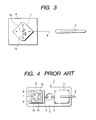
- Fig. 3 a drawing for describing the positional relationship between the patch antenna and the rod-shaped antenna in the dual antenna.
- Elements having counterparts in Fig. 4 are denoted by respectively the same reference signs.
- a dual antenna 20 shown in Figs. 1 and 2 is a vehicle-mountable compact antenna unit which has, over a base plate 2, a patch antenna 3 for receiving a circularly polarized electromagnetic wave from a GPS satellite, a rod-shaped antenna 4 for transmitting and receiving a linearly polarized electromagnetic wave for mobile telephony, the two antennas 3 and 4 being disposed in parallel and housed in a common radome 12.
- the patch antenna 3 is supplied with power via a cable 5 and a connector 13, and the rod-shaped antenna 4, via a cable 6 and a connector 14.
- the relative positions of these two antennas 3 and 4 are significantly different from their counterparts according to the prior art.
- the schematic configuration is such that the patch antenna 3 has a power feed patch 7, which is a radiation element of a microstrip structure provided over a dielectric substrate 8; this dielectric substrate 8 is mounted over a circuit board 9, and low-noise amplifier circuit components 16 including an amplifier and a band pass filter, all covered by a shield case 15, are packaged on the bottom face of the circuit board 9.
- a short axis 7a matching a mode (f1) of a higher resonance frequency and a long axis 7b matching a mode (f2) of a lower resonance frequency orthogonally cross each other, and excitation at a frequency between these high and low resonance frequencies f1 and f2 to generate a 90-degree phase difference between the radiation fields in the two modes can make the composite radiation field a circular polarization. This enables a circularly polarized electromagnetic wave of 1.575 GHz transmitted from a GPS satellite to be received by the patch antenna 3.
- the rod-shaped antenna 4 is fixed to a circuit board 11 adjoining the patch antenna 3, and erected in a slightly inclined state.
- This rod-shaped antenna 4 can transmit and receive electromagnetic waves of the 850 MHz band and the 1.85 GHz band used for mobile telephony, and is connected to a transmitter/receiver circuit via the cable 6 and the connector 14.
- the radome 12 (not shown) is fixed to the base plate 2, and covers internal component elements including the patch antenna 3 and the rod-shaped antenna 4.
- the angle ⁇ formed by a plane P to the intersection O between the short axis 7a and the long axis 7b of the power feed patch 7 of the rod-shaped antenna 4 can be set within the range of 85° ⁇ ⁇ ⁇ 95°.
- the plane of polarization of the linearly polarized electromagnetic wave radiated from the rod-shaped antenna 4 substantially coincides with the direction of the long axis 7b of the power feed patch 7 and substantially orthogonally crosses the direction of the short axis 7a, even if a powerful wave of a higher frequency than the desired frequency to be received by the patch antenna 3 (1.575 GHz) is radiated from the rod-shaped antenna 4, that high frequency electromagnetic wave will have almost no field component in the direction of the short axis 7a, and accordingly will hardly be received by the patch antenna 3.
- the patch antenna 3 of this dual antenna 20 even if a linearly polarized powerful electromagnetic wave for mobile telephony use is radiated from the adjoining rod-shaped antenna 4, is hardly susceptible to jamming and can receive, always in a satisfactory state, the circularly polarized relatively weak electromagnetic wave transmitted from the GPS satellite.
- the embodiment of the invention described above is supposed to use the patch antenna 3 for receiving a circularly polarized electromagnetic wave from a GPS satellite and the rod-shaped antenna 4 for transmitting and receiving a linearly polarized electromagnetic wave for mobile telephony use, the invention can obviously be applied to cases in which the patch antenna 3 and the rod-shaped antenna 4 are used for other purposes.
- the present invention can be carried out in the mode so far described and provide the following advantages.
- the direction of the power feed patch relative to the rod-shaped antenna is set so that the short axis substantially orthogonally crosses the plane containing the intersection between the short axis and the long axis of the power feed patch and the axis of the rod-shaped antenna, and the plane of polarization of the linearly polarized electromagnetic wave radiated from the rod-shaped antenna substantially coincides with the direction of the long axis of the power feed patch and substantially orthogonally crosses the direction of the short axis, even if a powerful wave of a higher frequency than the desired frequency to be received by the patch antenna is radiated from the rod-shaped antenna, that high frequency electromagnetic wave will hardly be received by the patch antenna.
- the patch antenna of this dual antenna even if a linearly polarized powerful electromagnetic wave for mobile telephony use is radiated from the adjoining rod-shaped antenna, is hardly susceptible to jamming and can receive, always in a satisfactory state, the circularly polarized relatively weak electromagnetic wave transmitted from the GPS satellite or the like, promising a high level of reliability.
Landscapes
- Engineering & Computer Science (AREA)
- Remote Sensing (AREA)
- Waveguide Aerials (AREA)
- Details Of Aerials (AREA)
- Support Of Aerials (AREA)
- Variable-Direction Aerials And Aerial Arrays (AREA)
Abstract
A direction of a power feed patch relative to a rod-shaped
antenna is set so that a short axis thereof substantially
orthogonally crosses a plane containing an intersection between
the short axis and a long axis of the power feed patch of a
patch antenna and an axis of the rod-shaped antenna. As a plane
of polarization of a linearly polarized electromagnetic wave
radiated from the rod-shaped antenna is thereby caused to
substantially coincide with a direction of the long axis of
the power feed patch and to substantially orthogonally cross
a direction of the short axis, even if a powerful wave of a
higher frequency than a desired frequency to be received by
the patch antenna and difficult to be removed by a band pass
filter of a low-noise amplifier circuit is radiated from the
rod-shaped antenna, field components of the high frequency
electromagnetic wave in the direction of the short axis will
become virtually zero.
Description
- The present invention relates to a dual antenna unitized by installing in parallel a patch antenna capable of transmitting and receiving a circularly polarized electromagnetic wave to and from a Global Positioning System (GPS) satellite or the like and a rod-shaped antenna capable of transmitting and receiving a linearly polarized electromagnetic wave for use in mobile telephony or the like.
- Vehicle-mountable patch antennas have been known since years ago as means for finding one' s current geographical position by receiving an electromagnetic wave from a GPS satellite, and more recently vehicle-mountable dual antennas, each combining a rod-shaped antenna for mobile telephone use with a patch antenna for GPS use, have become available for practical use. Such a dual antenna has a common radome compactly housing a patch antenna and a rod-shaped antenna. As it can be handled as a relatively small antenna unit combining the function to receive a circularly polarized electromagnetic wave from a GPS satellite and a function to receive a linearly polarized electromagnetic wave for use in mobile telephony, the dual antenna is expected to find use in many different areas along with the development and expansion of information and communication services.
- Fig. 4 shows a plan of such a dual antenna according to the prior art, in which the illustration of its radome is dispensed with. As illustrated, in a known dual antenna 1, a
patch antenna 3 and a rod-shaped antenna 4 are provided in parallel on abase plate 2, and these twoantennas 3 and 4 receive power supply viacables - To schematically describe its configuration, the
patch antenna 3 is fabricated by providing apower feed patch 7, which is a radiation element of a microstrip structure, over adielectric substrate 8, mounting thisdielectric substrate 8 on acircuit board 9, and packaging components of a low-noise amplifier circuit (not shown; including an amplifier and a band pass filter), covered by a shield case, on the bottom side of thecircuit board 9. For thepower feed patch 7, ashort axis 7a having a smaller resonance length matching a higher resonance frequency (f1) mode and along axis 7b having a greater resonance length matching a lower resonance frequency (f2) mode are defined by providing degenerate separating elements such as notches or projections, and theshort axis 7a and thelong axis 7b orthogonally cross each other. Excitation at a frequency between these high and low resonance frequencies f1 and f2 to generate a 90-degree phase difference between the radiation fields in the two modes can make the composite radiation field a circular polarization. This enables a circularly polarized electromagnetic wave of 1.575 GHz transmitted from a GPS satellite to be received by thepatch antenna 3. When it is received, of the electromagnetic wave higher in frequency than the resonance frequency f1, field components mainly in the direction of theshort axis 7a are received and, of the electromagnetic wave lower in frequency than the resonance frequency f2, field components mainly in the direction of thelong axis 7b are received. To add, as thepower feed patch 7 is connected to a low-noise amplifier circuit via apower feed pin 10, signals received by thepower feed patch 7 are delivered to a GPS receiver circuit (not shown) via thecable 5 and the like in a state in which they have been amplified by the amplifier and cleared of signals in the undesired frequency band by a band pass filter. - On the other hand, the rod-shaped antenna 4 is fixed to a
circuit board 11 adjoining thepatch antenna 3, and erected in a slightly inclined state. This rod-shaped antenna 4 can transmit and receive electromagnetic waves of the 850 MHz band and the 1.85 GHz band used for mobile telephony, and is connected to a transmitter/receiver (not shown) via thecable 6 and the like. The radome (not shown) is formed in such a shape as covers thepatch antenna 3 and the rod-shaped antenna 4 and fixed to thebase plate 2. - Incidentally, in the GPS reception unit of the dual antenna of the example of the prior art described above, if any undesired signal whose frequency is other than that of the desired receive signal is received by the
patch antenna 3, this undesired signal is usually removed by the band pass filter, and therefore it rarely interferes with the desired signal. However, if this undesired signal is a powerful electromagnetic wave for mobile telephony radiating from the adjoining rod-shaped antenna 4, there may arise a problem that the low-noise amplifier circuit is saturated with signals and invite interference. - An object of the present invention, attempted in view of this problem with the prior art, is to provide a highly reliable dual antenna made less susceptible to the adverse effect of the electromagnetic wave radiating from its rod-shaped antenna on an adjoining patch antenna.
- In order to achieve the object stated above, a dual antenna according to the invention is provided with a patch antenna having a power feed patch disposed over a dielectric substrate and capable of transmitting and receiving a circularly polarized electromagnetic wave and a rod-shaped antenna erected in the vicinity of the patch antenna and capable of transmitting and receiving a linearly polarized electromagnetic wave, wherein the power feed patch is formed by causing a short axis whose resonance length is set smaller and a long axis whose resonance length is set greater to orthogonally cross each other, and a direction of the power feed patch relative to the rod-shaped antenna is set so that the short axis substantially orthogonally crosses a plane containing an intersection between the short axis and long axis and an axis of the rod-shaped antenna. More specifically, it is preferable to set an angle formed by the plane and the short axis within a range of 85 degrees to 95 degrees.
- In the dual antenna configured in this manner, since the plane of polarization of the linearly polarized electromagnetic wave radiated from the rod-shaped antenna substantially coincides with the direction of the long axis of the power feed patch and substantially orthogonally crosses the direction of the short axis, even if a powerful wave of a higher frequency than the desired frequency to be received by the patch antenna is radiated from the rod-shaped antenna, that high frequency electromagnetic wave will have almost no field component in the direction of the short axis, and accordingly will hardly be received by the patch antenna. Or if a powerful wave of a lower frequency than the desired frequency to be received by the patch antenna is radiated from the rod-shaped antenna, as the plane of polarization of that low frequency electromagnetic wave substantially coincides with the direction of the long axis, it will be received by the patch antenna, but can be readily removed by the band pass filter of a low-noise amplifier circuit. Therefore, the patch antenna of this dual antenna, even if a linearly polarized powerful electromagnetic wave for mobile telephony use is radiated from an adjoining rod-shaped antenna, is hardly susceptible to jamming and can receive, always in a satisfactory state, the circularly polarized relatively weak electromagnetic wave transmitted from the GPS satellite or the like.
-
- Fig. 1 shows a schematic section of a dual antenna, which is a preferred embodiment of the present invention;
- Fig. 2 shows a plan of the dual antenna, in which the illustration of its radome is dispensed with;
- Fig. 3 is a drawing for describing the positional relationship between the patch antenna and the rod-shaped antenna in the dual antenna; and
- Fig. 4 shows a plan of the dual antenna according to the prior art, in which the illustration of its radome is dispensed with.
-
- To describe a preferred embodiment of the present invention with reference to accompanying drawings, Fig. 1 shows a schematic section of a dual antenna, which is the preferred embodiment of the invention; Fig. 2, a plan of the dual antenna, in which the illustration of its radome is dispensed with; and Fig. 3, a drawing for describing the positional relationship between the patch antenna and the rod-shaped antenna in the dual antenna. Elements having counterparts in Fig. 4 are denoted by respectively the same reference signs.
- A
dual antenna 20 shown in Figs. 1 and 2 is a vehicle-mountable compact antenna unit which has, over abase plate 2, apatch antenna 3 for receiving a circularly polarized electromagnetic wave from a GPS satellite, a rod-shaped antenna 4 for transmitting and receiving a linearly polarized electromagnetic wave for mobile telephony, the twoantennas 3 and 4 being disposed in parallel and housed in acommon radome 12. Thepatch antenna 3 is supplied with power via acable 5 and aconnector 13, and the rod-shaped antenna 4, via acable 6 and aconnector 14. In this embodiment of the invention, the relative positions of these twoantennas 3 and 4 are significantly different from their counterparts according to the prior art. - The schematic configuration is such that the
patch antenna 3 has apower feed patch 7, which is a radiation element of a microstrip structure provided over adielectric substrate 8; thisdielectric substrate 8 is mounted over acircuit board 9, and low-noiseamplifier circuit components 16 including an amplifier and a band pass filter, all covered by ashield case 15, are packaged on the bottom face of thecircuit board 9. In thepower feed patch 7, ashort axis 7a matching a mode (f1) of a higher resonance frequency and along axis 7b matching a mode (f2) of a lower resonance frequency orthogonally cross each other, and excitation at a frequency between these high and low resonance frequencies f1 and f2 to generate a 90-degree phase difference between the radiation fields in the two modes can make the composite radiation field a circular polarization. This enables a circularly polarized electromagnetic wave of 1.575 GHz transmitted from a GPS satellite to be received by thepatch antenna 3. When it is received, of the electromagnetic wave higher in frequency than the resonance frequency f1, field components mainly in the direction of theshort axis 7a are received and, of the electromagnetic wave lower in frequency than the resonance frequency f2, field components mainly in the direction of thelong axis 7b are received. To add, as thispower feed patch 7 is connected to a low-noise amplifier circuit via apower feed pin 10, signals received by thepower feed patch 7 are delivered to a GPS receiver circuit (not shown) via thecable 5 and theconnector 13 in a state in which they have been amplified by the amplifier and cleared of signals in the undesired frequency band by a band pass filter. - On the other hand, the rod-shaped antenna 4 is fixed to a
circuit board 11 adjoining thepatch antenna 3, and erected in a slightly inclined state. This rod-shaped antenna 4 can transmit and receive electromagnetic waves of the 850 MHz band and the 1.85 GHz band used for mobile telephony, and is connected to a transmitter/receiver circuit via thecable 6 and theconnector 14. The radome 12 (not shown) is fixed to thebase plate 2, and covers internal component elements including thepatch antenna 3 and the rod-shaped antenna 4. - To describe the positional relationship between the
patch antenna 3 and the rod-shaped antenna 4, as shown in Fig. 2, their relative positions are set so that theshort axis 7a substantially orthogonally crosses a plane containing the intersection between theshort axis 7a and thelong axis 7b of thepower feed patch 7 and the axis of the rod-shaped antenna 4. More specifically, as shown in Fig. 3, the angle formed by a plane P to the intersection O between theshort axis 7a and thelong axis 7b of thepower feed patch 7 of the rod-shaped antenna 4 can be set within the range of 85° ≤ ≤ 95°. - In the
dual antenna 20 configured in this manner, since the plane of polarization of the linearly polarized electromagnetic wave radiated from the rod-shaped antenna 4 substantially coincides with the direction of thelong axis 7b of thepower feed patch 7 and substantially orthogonally crosses the direction of theshort axis 7a, even if a powerful wave of a higher frequency than the desired frequency to be received by the patch antenna 3 (1.575 GHz) is radiated from the rod-shaped antenna 4, that high frequency electromagnetic wave will have almost no field component in the direction of theshort axis 7a, and accordingly will hardly be received by thepatch antenna 3. Or if a powerful wave of a lower frequency than the desired frequency to be received by thepatch antenna 3 is radiated from the rod-shaped antenna 4, as the plane of polarization of that low frequency electromagnetic wave substantially coincides with the direction of thelong axis 7b, it will be received by thepatch antenna 3, but can be readily removed by the band pass filter, which is one of the low-noiseamplifier circuit components 16. Therefore, thepatch antenna 3 of thisdual antenna 20, even if a linearly polarized powerful electromagnetic wave for mobile telephony use is radiated from the adjoining rod-shaped antenna 4, is hardly susceptible to jamming and can receive, always in a satisfactory state, the circularly polarized relatively weak electromagnetic wave transmitted from the GPS satellite. - To add, although the embodiment of the invention described above is supposed to use the
patch antenna 3 for receiving a circularly polarized electromagnetic wave from a GPS satellite and the rod-shaped antenna 4 for transmitting and receiving a linearly polarized electromagnetic wave for mobile telephony use, the invention can obviously be applied to cases in which thepatch antenna 3 and the rod-shaped antenna 4 are used for other purposes. - The present invention can be carried out in the mode so far described and provide the following advantages.
- As this is a dual antenna in which the direction of the power feed patch relative to the rod-shaped antenna is set so that the short axis substantially orthogonally crosses the plane containing the intersection between the short axis and the long axis of the power feed patch and the axis of the rod-shaped antenna, and the plane of polarization of the linearly polarized electromagnetic wave radiated from the rod-shaped antenna substantially coincides with the direction of the long axis of the power feed patch and substantially orthogonally crosses the direction of the short axis, even if a powerful wave of a higher frequency than the desired frequency to be received by the patch antenna is radiated from the rod-shaped antenna, that high frequency electromagnetic wave will hardly be received by the patch antenna. Or if a powerful wave of a lower frequency than the desired frequency to be received by the patch antenna is radiated from the rod-shaped antenna, that low frequency electromagnetic wave will be received by the patch antenna, but can be readily removed by the band pass filter of the low-noise amplifier circuit. Therefore, the patch antenna of this dual antenna, even if a linearly polarized powerful electromagnetic wave for mobile telephony use is radiated from the adjoining rod-shaped antenna, is hardly susceptible to jamming and can receive, always in a satisfactory state, the circularly polarized relatively weak electromagnetic wave transmitted from the GPS satellite or the like, promising a high level of reliability.
Claims (2)
- A dual antenna provided with a patch antenna having a power feed patch disposed over a dielectric substrate and capable of transmitting and receiving a circularly polarized electromagnetic wave and a rod-shaped antenna erected in the vicinity of the patch antenna and capable of transmitting and receiving a linearly polarized electromagnetic wave, wherein the power feed patch is formed by causing a short axis whose resonance length is set smaller and a long axis whose resonance length is set greater to orthogonally cross each other, and wherein a direction of the power feed patch relative to the rod-shaped antenna is set so that the short axis substantially orthogonally crosses a plane containing an intersection between the short axis and long axis and an axis of the rod-shaped antenna.
- The dual antenna according to Claim 1, wherein an angle formed by the plane and the short axis is set within a range of 85 degrees to 95 degrees.
Applications Claiming Priority (2)
| Application Number | Priority Date | Filing Date | Title |
|---|---|---|---|
| JP2002114974A JP2003309411A (en) | 2002-04-17 | 2002-04-17 | Compound antenna |
| JP2002114974 | 2002-04-17 |
Publications (1)
| Publication Number | Publication Date |
|---|---|
| EP1355375A1 true EP1355375A1 (en) | 2003-10-22 |
Family
ID=28672645
Family Applications (1)
| Application Number | Title | Priority Date | Filing Date |
|---|---|---|---|
| EP03252231A Withdrawn EP1355375A1 (en) | 2002-04-17 | 2003-04-09 | Dual antenna |
Country Status (3)
| Country | Link |
|---|---|
| US (1) | US6879294B2 (en) |
| EP (1) | EP1355375A1 (en) |
| JP (1) | JP2003309411A (en) |
Cited By (3)
| Publication number | Priority date | Publication date | Assignee | Title |
|---|---|---|---|---|
| CN1893177B (en) * | 2005-06-28 | 2012-09-05 | 三美电机株式会社 | Hybrid antenna unit |
| EP2270921A4 (en) * | 2008-04-25 | 2013-12-18 | Clarion Co Ltd | COMPOSITE ANTENNA DEVICE |
| US8836590B2 (en) | 2009-06-11 | 2014-09-16 | Electro-Motive Diesel, Inc. | Locomotive modular antenna array |
Families Citing this family (32)
| Publication number | Priority date | Publication date | Assignee | Title |
|---|---|---|---|---|
| US6032041A (en) * | 1997-06-02 | 2000-02-29 | Hughes Electronics Corporation | Method and system for providing wideband communications to mobile users in a satellite-based network |
| JP3791492B2 (en) * | 2002-12-25 | 2006-06-28 | 株式会社日立製作所 | Rotating electric machine, electric vehicle, and resin insert molding method |
| JP2005073168A (en) * | 2003-08-27 | 2005-03-17 | Uniden Corp | Re-radiating antenna system |
| US7446707B2 (en) * | 2004-04-16 | 2008-11-04 | Micro-Ant, Inc. | Ultra-low profile vehicular antenna methods and systems |
| US20060055603A1 (en) * | 2004-09-10 | 2006-03-16 | Joseph Jesson | Concealed planar antenna |
| GB0426319D0 (en) * | 2004-12-01 | 2005-01-05 | Finglas Technologies Ltd | Remote control of antenna line device |
| US7224319B2 (en) * | 2005-01-07 | 2007-05-29 | Agc Automotive Americas R&D Inc. | Multiple-element beam steering antenna |
| US7239281B2 (en) * | 2005-04-06 | 2007-07-03 | Yeoujyi Electronics Co., Ltd. | Fin-shaped antenna apparatus for vehicle radio application |
| US7755551B2 (en) | 2005-11-10 | 2010-07-13 | Laird Technologies, Inc. | Modular antenna assembly for automotive vehicles |
| US7333065B2 (en) * | 2005-11-10 | 2008-02-19 | Receptec Holdings, Llc | Modular antenna assembly for automotive vehicles |
| JP4656317B2 (en) | 2006-01-24 | 2011-03-23 | ミツミ電機株式会社 | Antenna device |
| JP4607039B2 (en) * | 2006-03-20 | 2011-01-05 | ミツミ電機株式会社 | Antenna device |
| JP4798368B2 (en) | 2006-09-04 | 2011-10-19 | ミツミ電機株式会社 | Compound antenna device |
| JP4807204B2 (en) * | 2006-09-19 | 2011-11-02 | ミツミ電機株式会社 | Antenna device |
| JP2008078720A (en) * | 2006-09-19 | 2008-04-03 | Mitsumi Electric Co Ltd | Antenna device |
| US7492319B2 (en) * | 2006-09-22 | 2009-02-17 | Laird Technologies, Inc. | Antenna assemblies including standard electrical connections and captured retainers and fasteners |
| US20080100521A1 (en) * | 2006-10-30 | 2008-05-01 | Derek Herbert | Antenna assemblies with composite bases |
| US7429958B2 (en) * | 2006-11-28 | 2008-09-30 | Laird Technologies, Inc. | Vehicle-mount antenna assemblies having snap-on outer cosmetic covers with compliant latching mechanisms for achieving zero-gap |
| US7592960B2 (en) * | 2006-12-05 | 2009-09-22 | Delphi Technologies, Inc. | High frequency capacitive coupling antenna for vehicles |
| US7714785B2 (en) * | 2007-07-12 | 2010-05-11 | Inpaq Technology Co., Ltd. | GPS antenna module and manufacturing method thereof |
| US7768465B2 (en) * | 2007-09-12 | 2010-08-03 | Laird Technologies, Inc. | Vehicle-mount stacked patch antenna assemblies with resiliently compressible bumpers for mechanical compression to aid in electrical grounding of shield and chassis |
| JP4600695B2 (en) * | 2008-04-23 | 2010-12-15 | ミツミ電機株式会社 | Compound antenna device |
| USD643026S1 (en) | 2010-11-15 | 2011-08-09 | World Products, Llc | Antenna radome plate |
| USD643025S1 (en) | 2010-11-15 | 2011-08-09 | World Products, Llc | Antenna radome |
| CN103533950A (en) | 2011-01-13 | 2014-01-22 | 瑞泽恩制药公司 | Use of a vegf antagonist to treat angiogenic eye disorders |
| US8803749B2 (en) * | 2011-03-25 | 2014-08-12 | Kwok Wa Leung | Elliptically or circularly polarized dielectric block antenna |
| GB201213558D0 (en) | 2012-07-31 | 2012-09-12 | Univ Birmingham | Reconfigurable antenna |
| GB2507788A (en) | 2012-11-09 | 2014-05-14 | Univ Birmingham | Vehicle roof mounted reconfigurable MIMO antenna |
| US10008767B2 (en) | 2016-04-29 | 2018-06-26 | Laird Technologies, Inc. | Vehicle-mount antenna assemblies having outer covers with back tension latching mechanisms for achieving zero-gap |
| KR101827706B1 (en) * | 2016-09-20 | 2018-02-12 | 현대자동차주식회사 | Vehicle and control method for the vehicle |
| EP3660978B1 (en) | 2017-08-24 | 2022-09-28 | Ntt Docomo, Inc. | Antenna device, wireless base station, and antenna device container |
| USD926164S1 (en) * | 2018-04-04 | 2021-07-27 | Taoglas Group Holdings Limited | Vehicle antenna |
Citations (6)
| Publication number | Priority date | Publication date | Assignee | Title |
|---|---|---|---|---|
| EP0590955A2 (en) * | 1992-09-30 | 1994-04-06 | Loral Aerospace Corporation | Multiple band antenna |
| DE29500961U1 (en) * | 1995-01-13 | 1995-06-14 | Richard Hirschmann GmbH & Co., 72654 Neckartenzlingen | Antenna arrangement |
| US5610620A (en) * | 1995-05-19 | 1997-03-11 | Comant Industries, Inc. | Combination antenna |
| EP0862239A1 (en) * | 1996-09-13 | 1998-09-02 | Nippon Antena Kabushiki Kaisha | Multiple frequency antenna |
| US5831577A (en) * | 1995-08-03 | 1998-11-03 | Trimble Navigation Limited | GPS/radio antenna combination |
| US6313801B1 (en) * | 2000-08-25 | 2001-11-06 | Telefonaktiebolaget Lm Ericsson | Antenna structures including orthogonally oriented antennas and related communications devices |
Family Cites Families (1)
| Publication number | Priority date | Publication date | Assignee | Title |
|---|---|---|---|---|
| JPH10107542A (en) | 1996-09-27 | 1998-04-24 | Yokowo Co Ltd | Antenna system |
-
2002
- 2002-04-17 JP JP2002114974A patent/JP2003309411A/en not_active Withdrawn
-
2003
- 2003-04-09 EP EP03252231A patent/EP1355375A1/en not_active Withdrawn
- 2003-04-17 US US10/417,491 patent/US6879294B2/en not_active Expired - Fee Related
Patent Citations (6)
| Publication number | Priority date | Publication date | Assignee | Title |
|---|---|---|---|---|
| EP0590955A2 (en) * | 1992-09-30 | 1994-04-06 | Loral Aerospace Corporation | Multiple band antenna |
| DE29500961U1 (en) * | 1995-01-13 | 1995-06-14 | Richard Hirschmann GmbH & Co., 72654 Neckartenzlingen | Antenna arrangement |
| US5610620A (en) * | 1995-05-19 | 1997-03-11 | Comant Industries, Inc. | Combination antenna |
| US5831577A (en) * | 1995-08-03 | 1998-11-03 | Trimble Navigation Limited | GPS/radio antenna combination |
| EP0862239A1 (en) * | 1996-09-13 | 1998-09-02 | Nippon Antena Kabushiki Kaisha | Multiple frequency antenna |
| US6313801B1 (en) * | 2000-08-25 | 2001-11-06 | Telefonaktiebolaget Lm Ericsson | Antenna structures including orthogonally oriented antennas and related communications devices |
Cited By (3)
| Publication number | Priority date | Publication date | Assignee | Title |
|---|---|---|---|---|
| CN1893177B (en) * | 2005-06-28 | 2012-09-05 | 三美电机株式会社 | Hybrid antenna unit |
| EP2270921A4 (en) * | 2008-04-25 | 2013-12-18 | Clarion Co Ltd | COMPOSITE ANTENNA DEVICE |
| US8836590B2 (en) | 2009-06-11 | 2014-09-16 | Electro-Motive Diesel, Inc. | Locomotive modular antenna array |
Also Published As
| Publication number | Publication date |
|---|---|
| US20030197651A1 (en) | 2003-10-23 |
| JP2003309411A (en) | 2003-10-31 |
| US6879294B2 (en) | 2005-04-12 |
Similar Documents
| Publication | Publication Date | Title |
|---|---|---|
| US6879294B2 (en) | Dual antenna capable of transmitting and receiving circularly polarized electromagnetic wave and linearly polarized electromagnetic wave | |
| US6218997B1 (en) | Antenna for a plurality of radio services | |
| US6549167B1 (en) | Patch antenna for generating circular polarization | |
| CN1206815C (en) | Folded inverted f antenna for gps applications | |
| US7372412B2 (en) | Transceiver-integrated antenna | |
| US9728845B2 (en) | Dual antenna structure having circular polarisation characteristics | |
| JP2000307341A (en) | Antenna system | |
| CN101771198A (en) | composite antenna element | |
| US8514137B2 (en) | Composite antenna device | |
| US5945950A (en) | Stacked microstrip antenna for wireless communication | |
| US7486245B2 (en) | Mobile terminal with plural antennas | |
| WO2008075156A1 (en) | Antenna for a portable device | |
| US20100109962A1 (en) | Circularly polarized antenna and an electronic device having the circularly polarized antenna | |
| KR20070086771A (en) | Wireless Communication Device Antennas for Improved Satellite Communication | |
| JP2000082914A (en) | Microstrip antenna, antenna device using the antenna and radio device | |
| EP4057442B1 (en) | Antenna assembly and terminal | |
| JP6509271B2 (en) | Dual-polarization antenna, antenna unit, and watch | |
| JP2001024426A (en) | Antenna element and circularly polarized antenna system using the same | |
| CN114171907A (en) | Dual-frequency low-orbit occultation GNSS antenna | |
| GB2429336A (en) | Compact loop antenna | |
| JP4461069B2 (en) | Compound antenna device | |
| KR20080012501A (en) | Internal and external combined antenna device of mobile terminal | |
| WO2026087936A1 (en) | High-performance circular polarization in a compact antenna design | |
| FI129219B (en) | Antenna assembly for customizable devices | |
| KR100406965B1 (en) | Duplexer with built-in antenna for global positioning system |
Legal Events
| Date | Code | Title | Description |
|---|---|---|---|
| PUAI | Public reference made under article 153(3) epc to a published international application that has entered the european phase |
Free format text: ORIGINAL CODE: 0009012 |
|
| AK | Designated contracting states |
Kind code of ref document: A1 Designated state(s): AT BE BG CH CY CZ DE DK EE ES FI FR GB GR HU IE IT LI LU MC NL PT RO SE SI SK TR |
|
| AX | Request for extension of the european patent |
Extension state: AL LT LV MK |
|
| 17P | Request for examination filed |
Effective date: 20030924 |
|
| 17Q | First examination report despatched |
Effective date: 20031126 |
|
| AKX | Designation fees paid |
Designated state(s): DE FR GB |
|
| STAA | Information on the status of an ep patent application or granted ep patent |
Free format text: STATUS: THE APPLICATION IS DEEMED TO BE WITHDRAWN |
|
| 18D | Application deemed to be withdrawn |
Effective date: 20040407 |