EP1355321A2 - Method and apparatus of multi-energy imaging - Google Patents
Method and apparatus of multi-energy imaging Download PDFInfo
- Publication number
- EP1355321A2 EP1355321A2 EP03252379A EP03252379A EP1355321A2 EP 1355321 A2 EP1355321 A2 EP 1355321A2 EP 03252379 A EP03252379 A EP 03252379A EP 03252379 A EP03252379 A EP 03252379A EP 1355321 A2 EP1355321 A2 EP 1355321A2
- Authority
- EP
- European Patent Office
- Prior art keywords
- electromagnetic energy
- energy source
- filter
- subject
- voltage
- Prior art date
- Legal status (The legal status is an assumption and is not a legal conclusion. Google has not performed a legal analysis and makes no representation as to the accuracy of the status listed.)
- Withdrawn
Links
Images




Classifications
-
- A—HUMAN NECESSITIES
- A61—MEDICAL OR VETERINARY SCIENCE; HYGIENE
- A61B—DIAGNOSIS; SURGERY; IDENTIFICATION
- A61B6/00—Apparatus or devices for radiation diagnosis; Apparatus or devices for radiation diagnosis combined with radiation therapy equipment
- A61B6/40—Arrangements for generating radiation specially adapted for radiation diagnosis
- A61B6/4035—Arrangements for generating radiation specially adapted for radiation diagnosis the source being combined with a filter or grating
-
- A—HUMAN NECESSITIES
- A61—MEDICAL OR VETERINARY SCIENCE; HYGIENE
- A61B—DIAGNOSIS; SURGERY; IDENTIFICATION
- A61B6/00—Apparatus or devices for radiation diagnosis; Apparatus or devices for radiation diagnosis combined with radiation therapy equipment
- A61B6/02—Arrangements for diagnosis sequentially in different planes; Stereoscopic radiation diagnosis
- A61B6/03—Computed tomography [CT]
- A61B6/032—Transmission computed tomography [CT]
-
- A—HUMAN NECESSITIES
- A61—MEDICAL OR VETERINARY SCIENCE; HYGIENE
- A61B—DIAGNOSIS; SURGERY; IDENTIFICATION
- A61B6/00—Apparatus or devices for radiation diagnosis; Apparatus or devices for radiation diagnosis combined with radiation therapy equipment
- A61B6/40—Arrangements for generating radiation specially adapted for radiation diagnosis
- A61B6/405—Source units specially adapted to modify characteristics of the beam during the data acquisition process
-
- A—HUMAN NECESSITIES
- A61—MEDICAL OR VETERINARY SCIENCE; HYGIENE
- A61B—DIAGNOSIS; SURGERY; IDENTIFICATION
- A61B6/00—Apparatus or devices for radiation diagnosis; Apparatus or devices for radiation diagnosis combined with radiation therapy equipment
- A61B6/48—Diagnostic techniques
- A61B6/482—Diagnostic techniques involving multiple energy imaging
-
- G—PHYSICS
- G21—NUCLEAR PHYSICS; NUCLEAR ENGINEERING
- G21K—HANDLING OF PARTICLES OR IONISING RADIATION NOT OTHERWISE PROVIDED FOR; IRRADIATION DEVICES; GAMMA RAY OR X-RAY MICROSCOPES
- G21K1/00—Arrangements for handling particles or ionising radiation, e.g. focusing or moderating
- G21K1/10—Scattering devices; Absorbing devices; Ionising radiation filters
Definitions
- the present invention relates generally to diagnostic imaging and, more particularly, to a method and apparatus of acquiring imaging data at more than one energy range using multi-energy high speed switching filters.
- an x-ray source emits a fan-shaped beam toward a subject or object, such as a patient or a piece of luggage.
- the beam after being attenuated by the subject, impinges upon an array of radiation detectors.
- the intensity of the attenuated beam radiation received at the detector array is typically dependent upon the attenuation of the x-ray beam by the subject.
- Each detector element of the detector array produces a separate electrical signal indicative of the attenuated beam received by each detector element.
- the electrical signals are transmitted to a data processing system for analysis which ultimately produces an image.
- X-ray sources typically include x-ray tubes, which emit the x-ray beam at a focal point.
- X-ray detectors typically include a collimator for collimating x-ray beams received at the detector, a scintillator for converting x-rays to light energy adjacent the collimator, and photodiodes for receiving the light energy from the adjacent scintillator and producing electrical signals therefrom.
- each scintillator of a scintillator array converts x-rays to light energy.
- Each scintillator discharges light energy to a photodiode adjacent thereto.
- Each photodiode detects the light energy and generates a corresponding electrical signal. The outputs of the photodiodes are then transmitted to the data processing system for image reconstruction.
- dual energy CT scanning commonly referred to as "tomochemistry” has increasingly been used as a means of gaining diagnostic information of a subject.
- a principle objective of dual energy scanning is to obtain diagnostic CT images that enhance contrast separation within the image by utilizing two scans at different chromatic energy states.
- a number of techniques have been proposed to achieve dual energy scanning including a "Two Crystal” method and a “Two kV” method. These two techniques were discussed by F. Kelcz, et al. in an article in Medical Physics 6(5), SEP./OCT.
- the present invention is directed to a method and apparatus of multi-energy imaging overcoming the aforementioned drawbacks.
- a set of rotatable filters is provided and controlled by a controller configured to position each filter in a path of high frequency electromagnetic energy synchronously with a changing kVp cycle.
- a burst of high frequency electromagnetic energy beams may be generated at a desired energy/filtration combination for each view.
- a set of views properly filtered for the high frequency electromagnetic energy implemented may then be generated and used for image reconstruction.
- a CT system comprises a rotatable gantry having an opening for receiving a subject to be scanned.
- the CT system further includes a high frequency electromagnetic energy source configured to project a number of high frequency electromagnetic energy beams towards the subject.
- a generator is also provided and configured to energize the high frequency electromagnetic energy source to at least a first energy state and a second energy state.
- the CT system also includes a number of high frequency electromagnetic energy filters positionable between the high frequency electromagnetic energy source and the subject.
- the number of high frequency electromagnetic energy filters includes at least a first filter and a second filter wherein the first filter is positioned between the high frequency electromagnetic energy source and the subject when the high frequency electromagnetic energy source is energized to the first energy state.
- the second filter is configured to be positioned between the high frequency electromagnetic energy source and the subject when the high frequency electromagnetic energy source is energized to the second energy state.
- a controller is configured to acquire CT imaging data at more than one chromatic energy state.
- the controller has instructions to energize a high frequency electromagnetic energy source configured to project a high frequency electromagnetic energy beam toward a subject to be scanned to a first voltage potential.
- the controller has further instructions to position a first portion of a filtering apparatus between the subject and the high frequency electromagnetic energy source along a path of rotation during energization of the high frequency electromagnetic energy source to the first voltage potential.
- the controller also has instructions to energize the high frequency electromagnetic energy source to a second voltage potential. The controller is then instructed to position a second portion of the filtering apparatus between the subject and the high frequency electromagnetic energy source along the path of rotation during energization of the high frequency electromagnetic energy source to the second voltage potential.
- a method of acquiring imaging data at more than one chromatic energy comprises the step of projecting a first beam of electromagnetic energy along a projection path toward a subject. The method further includes the step of positioning a first filter in the projection path during projection of the first beam. The method also includes projecting a second beam of electromagnetic energy along the projection path toward the subject and positioning a second filter in the projection path during projection of the second beam of electromagnetic energy.
- a computer readable storage medium has a computer program stored thereon.
- the computer program represents a set of instructions that when executed by a computer causes the computer to energize the high frequency electromagnetic energy source to a first voltage to cause the high frequency electromagnetic energy source to project a first beam of electromagnetic energy toward the subject to be scanned.
- the computer is further caused to position a first filter between the high frequency electromagnetic energy source and the subject during energization of the high frequency electromagnetic energy source to the first voltage.
- the set of instructions further causes the computer to energize the high frequency electromagnetic energy source to a second voltage to cause the high frequency electromagnetic energy source to project a second beam of electromagnetic energy toward the subject and position a second filter between the electromagnetic energy source and the subject during energization of the high frequency electromagnetic energy source to the second voltage.
- a filtering apparatus for a radiation emitting imaging system.
- the filtering apparatus includes a hub having a number of connection ports and a first filter connected to the hub at a first connection port and a second filter connected to the hub at a second connection port.
- the first filter is configured to have a first filtering power and the second filter is configured to have a second filtering power.
- CT computed tomography
- a computed tomography (CT) imaging system 10 is shown as including a gantry 12 representative of a "third generation" CT scanner.
- Gantry 12 has an x-ray source 14 that projects a beam of x-rays 16 toward a filtering apparatus 17 and a detector array 18 on the opposite side of the gantry 12.
- the filtering apparatus 17 may include a pre-patient filter, a post-patient filter, or both.
- the filtering apparatus 17 is shown as a pre-patient filter, as will be described more fully with respect to Figs. 6-8.
- Detector array 18 is formed by a plurality of detectors 20 which together sense the projected x-rays that pass through a medical patient 22.
- Each detector 20 produces an electrical signal that represents the intensity of an impinging x-ray beam and hence the attenuated beam as it passes through the patient 22.
- gantry 12 and the components mounted thereon including source 14, filtering apparatus 17, and detector array 18 rotate about a center of rotation 24.
- control mechanism 26 includes a filter controller 27 that provides positioning signals to filtering apparatus 17.
- Control mechanism 26 also includes an x-ray controller 28 that provides power and timing signals to an x-ray source 14 and a gantry motor controller 30 that controls the rotational speed and position of gantry 12.
- a data acquisition system (DAS) 32 in control mechanism 26 samples analog data from detectors 20 and converts the data to digital signals for subsequent processing.
- An image reconstructor 34 receives sampled and digitized x-ray data from DAS 32 and performs high speed reconstruction. The reconstructed image is applied as an input to a computer 36 which stores the image in a mass storage device 38.
- DAS data acquisition system
- Computer 36 also receives commands and scanning parameters from an operator via console 40 that has a keyboard or other data entry module.
- An associated display 42 allows the operator to observe the reconstructed image and other data from computer 36.
- the operator supplied commands and parameters are used by computer 36 to provide control signals and information to DAS 32, x-ray controller 28 and gantry motor controller 30.
- computer 36 operates a table motor controller 44 which controls a motorized table 46 to position patient 22 and gantry 12. Particularly, table 46 moves portions of patient 22 through a gantry opening 48.
- detector array 18 includes a plurality of photodiodes 60 forming a photodiode array 52 and a plurality of scintillators 57 forming a scintillator array 56.
- a collimator (not shown) is positioned above scintillator array 56 to collimate x-ray beams 16 before such beams impinge upon scintillator array 56.
- detector array 18 includes 57 detectors 20, each detector 20 having an array size of 16 x 16. As a result, array 18 has 16 rows and 912 columns (16 x 57 detectors) which allows 16 simultaneous slices of data to be collected with each rotation of gantry 12.
- Switch arrays 80 and 82 are multi-dimensional semiconductor arrays coupled between scintillator array 56 and DAS 32.
- Switch arrays 80 and 82 include a plurality of field effect transistors (FET) (not shown) arranged as multi-dimensional array.
- the FET array includes a number of electrical leads connected to each of the respective photodiodes 60 and a number of output leads electrically connected to DAS 32 via a flexible electrical interface 84.
- a reflector material 59 is interstitially disposed between each scintillator 57 to reduce light spreading from adjacent scintillators.
- Each detector 20 is secured to a detector frame 77, Fig. 3, by mounting brackets 79.
- Switch arrays 80 and 82 further include a decoder (not shown) that enables, disables, or combines photodiode outputs in accordance with a desired number of slices and slice resolutions for each slice.
- Decoder in one embodiment, is a decoder chip or a FET controller as known in the art. Decoder includes a plurality of output and control lines coupled to switch arrays 80 and 82 and DAS 32. In one embodiment defined as a 16 slice mode, decoder enables switch arrays 80 and 82 so that all rows of the photodiode array 52 are activated, resulting in 16 simultaneous slices of data for processing by DAS 32. Of course, many other slice combinations are possible. For example, decoder may also select from other slice modes, including one, two, and four-slice modes.
- switch arrays 80 and 82 can be configured in the four-slice mode so that the data is collected from four slices of one or more rows of photodiode array 52.
- various combinations of photodiodes 60 can be enabled, disabled, or combined so that the slice thickness may consist of one, two, three, or four rows of scintillator array elements 57. Additional examples include, a single slice mode including one slice with slices ranging from 1.25 mm thick to 20 mm thick, and a two slice mode including two slices with slices ranging from 1.25 mm thick to 10 mm thick. Additional modes beyond those described are contemplated.
- Filtering apparatus 17 includes a hub 86 having a number of connection ports 88. In this embodiment, a connection port 88 is positioned every 90° around the hub. Hub 86 is shown as a cylinder but a spherical hub is also contemplated. In a three-spoked filtering apparatus, each connection port would be located every 120° along the hub.
- each filter member 90 may be connected to hub 86 at connection port 88 in a number of known manners.
- filtering member 92-96 may be snap-fit, bolted, or integrated with hub 86 as a single integral body.
- each connection port 86 includes a slot for receiving a filter but other receiving designs are contemplated.
- each filtering member 92-96 has a differing filtering power. That is, filtering member 90 has a filtering power different from the filtering power of filter 94 and so forth.
- Hub 86 includes circuitry (not shown) that responds to electrical signals generated by filter controller 27, Fig. 2, to position one of the filters 90-96 in a path of high frequency electromagnetic energy. Hub 86 is thereby caused to rotate filters 90-96 into the high frequency electromagnetic energy path synchronously with energization of the high frequency electromagnetic energy projection source 14 of Fig. 1. The synchronous relationship of filter position and source energization is best shown in Fig. 7.
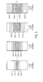
- Fig. 7 Shown in Fig. 7 are three plots illustrating the position of each filter with respect to the kVp potential of the high frequency electromagnetic energy source.
- a first filter such as filter 90
- the x-ray source then emits a second burst of x-rays having a kVp potential B and simultaneously therewith filter 92 is positioned in the x-ray path. Thereafter, the x-ray source emits another burst of x-rays having a kVp potential C. Simultaneously therewith, filter 94 is rotated by the hub into the x-ray path.
- the x-ray source is then instructed to emit another burst of x-rays having a kVp potential D.
- the filter controller transmits a signal to the filtering apparatus to position filter 96 in the x-ray path.
- Fig. 7 illustrates the positioning of each filter in the x-ray path depending upon the kVp potential of the beam of x-rays.
- the present invention does not require the sequential placement of each filter as described above. That is, depending upon the requirements of the imaging protocol filter 96 may be positioned in the x-ray path after filter 90. Ultimately, the order by which the filters are positioned in the x-ray path is not limited to the sequential description provided above.
- Filtering apparatus 98 may be used with or independently of filtering apparatus 17 specifically described in Fig. 6.
- filtering apparatus 98 includes a single filter comprising a number of filtering sections 100-106. Each filtering section 100-106 has a different filtering power. Therefore, filtering apparatus 98 may be used for multi-energy CT scanning.
- Filtering apparatus 98 is designed such that one section 100-106 is positioned in the x-ray path depending upon the kVp potential of the x-ray beam. For example, when the x-ray beam has a high kVp potential filtering section 100 may be positioned in the x-ray path.
- Filtering apparatus 98 is shown as comprising four separate and distinct filtering sections. However, the present invention is not limited to only four sections and therefore a filtering apparatus with less than four sections or more than four sections is equivalently applicable with the present invention.
- the filtering apparatus 98 shown in Fig. 8 is incorporated with the four-spoked filtering apparatus 17 illustrated in Fig. 6.
- each filter 90-96 has a number of filtering sections similar to that shown in Fig. 8.
- the number of filtering combinations can be increased without requiring multiple filtering apparatuses.
- a total of sixteen filtering combinations may be utilized in acquiring imaging data.
- package/baggage inspection system 100 includes a rotatable gantry 102 having an opening 104 therein through which packages or pieces of baggage may pass.
- the rotatable gantry 102 houses a high frequency electromagnetic energy source 106 and a filtering apparatus 107, as well as a detector assembly 108.
- Filtering apparatus 107 is shown as being positioned between the source106 and object 116. However, filtering apparatus 107 could be placed between object 116 and detector assembly 108.
- a first filter is positioned pre-object and a second filter positioned post-object.
- a conveyor system 110 is also provided and includes a conveyor belt 112 supported by structure 114 to automatically and continuously pass packages or baggage pieces 116 through opening 104 to be scanned.
- Objects 116 are fed through opening 104 by conveyor belt 112, imaging data is then acquired, and the conveyor belt 112 removes the packages 116 from opening 104 in a controlled and continuous manner.
- postal inspectors, baggage handlers, and other security personnel may non-invasively inspect the contents of packages 116 for explosives, knives, guns, contraband, etc. by viewing the images on a display (not shown).
- a CT system comprises a rotatable gantry having an opening for receiving a subject to be scanned.
- the CT system further includes a high frequency electromagnetic energy source configured to project a number of high frequency electromagnetic energy beams towards the subject.
- a generator is also provided and configured to energize the high frequency electromagnetic energy source to at least a first energy state and a second energy state.
- the CT system also includes a number of high frequency electromagnetic energy filters positionable between the high frequency electromagnetic energy source and the subject.
- the number of high frequency electromagnetic energy filters includes at least a first filter and a second filter wherein the first filter is positioned between the high frequency electromagnetic energy source and the subject when the high frequency electromagnetic energy source is energized to the first energy state.
- the second filter is configured to be positioned between the high frequency electromagnetic energy source and the subject when the high frequency electromagnetic energy source is energized to the second energy state.
- a controller is configured to acquire CT imaging data in more than one chromatic energy state.
- the controller has instructions to energize a high frequency electromagnetic energy source configured to project a high frequency electromagnetic energy beam toward a subject to be scanned to a first voltage potential.
- the controller has further instructions to position a first portion of a filtering apparatus between the subject and the high frequency electromagnetic energy source along a path of rotation during energization of the high frequency electromagnetic energy source to the first voltage potential.
- the controller also has instructions to energize the high frequency electromagnetic energy source to a second voltage potential. The controller is then instructed to position a second portion of the filtering apparatus between the subject and the high frequency electromagnetic energy source along the path of rotation during energization of the high frequency electromagnetic energy source to the second voltage potential.
- a method of acquiring imaging data at more than one chromatic energy comprises the step of projecting a first beam of electromagnetic energy along a projection path toward a subject.
- the method further includes the step of positioning a first filter in the projection path during projection of the first beam.
- the method also includes projecting a second beam of electromagnetic energy along the projection path toward the subject and includes the step of positioning a second filter in the projection path during projection of the second beam of electromagnetic energy.
- a computer readable storage medium has a computer program stored thereon.
- the computer program represents a set of instructions that when executed by a computer causes the computer to energize high frequency electromagnetic energy source to a first voltage to cause the high frequency electromagnetic energy source to project a first beam of electromagnetic energy toward the subject to be scanned.
- the computer is further caused to position a first filter between the high frequency electromagnetic energy source and the subject during energization of the high frequency electromagnetic energy source to the first voltage.
- the set of instructions further causes the computer to energize the high frequency electromagnetic energy source to a second voltage to cause the high frequency electromagnetic energy source to project a second beam of electromagnetic energy toward the subject and position a second filter between the electromagnetic energy source and the subject during energization of the high frequency electromagnetic energy source to the second voltage.
- a filtering apparatus for a radiation emitting imaging system.
- the filtering apparatus includes a hub having a number of connection ports and a first filter connected to the hub at a first connection port and a second filter connected to the hub at a second connection port.
- the first filter is configured to have a first filtering power and the second filter is configured to have a second filtering power.
Landscapes
- Health & Medical Sciences (AREA)
- Life Sciences & Earth Sciences (AREA)
- Engineering & Computer Science (AREA)
- Medical Informatics (AREA)
- Physics & Mathematics (AREA)
- High Energy & Nuclear Physics (AREA)
- Radiology & Medical Imaging (AREA)
- Molecular Biology (AREA)
- Veterinary Medicine (AREA)
- Nuclear Medicine, Radiotherapy & Molecular Imaging (AREA)
- Optics & Photonics (AREA)
- Pathology (AREA)
- Public Health (AREA)
- Biomedical Technology (AREA)
- Heart & Thoracic Surgery (AREA)
- Biophysics (AREA)
- Surgery (AREA)
- Animal Behavior & Ethology (AREA)
- General Health & Medical Sciences (AREA)
- Pulmonology (AREA)
- Theoretical Computer Science (AREA)
- Spectroscopy & Molecular Physics (AREA)
- General Engineering & Computer Science (AREA)
- Apparatus For Radiation Diagnosis (AREA)
- Analysing Materials By The Use Of Radiation (AREA)
Abstract
Description
- The present invention relates generally to diagnostic imaging and, more particularly, to a method and apparatus of acquiring imaging data at more than one energy range using multi-energy high speed switching filters.
- Typically, in computed tomography (CT) imaging systems, an x-ray source emits a fan-shaped beam toward a subject or object, such as a patient or a piece of luggage. Hereinafter, the terms "subject" and "object" shall include anything capable of being imaged. The beam, after being attenuated by the subject, impinges upon an array of radiation detectors. The intensity of the attenuated beam radiation received at the detector array is typically dependent upon the attenuation of the x-ray beam by the subject. Each detector element of the detector array produces a separate electrical signal indicative of the attenuated beam received by each detector element. The electrical signals are transmitted to a data processing system for analysis which ultimately produces an image.
- Generally, the x-ray source and the detector array are rotated about the gantry within an imaging plane and around the subject. X-ray sources typically include x-ray tubes, which emit the x-ray beam at a focal point. X-ray detectors typically include a collimator for collimating x-ray beams received at the detector, a scintillator for converting x-rays to light energy adjacent the collimator, and photodiodes for receiving the light energy from the adjacent scintillator and producing electrical signals therefrom.
- Typically, each scintillator of a scintillator array converts x-rays to light energy. Each scintillator discharges light energy to a photodiode adjacent thereto. Each photodiode detects the light energy and generates a corresponding electrical signal. The outputs of the photodiodes are then transmitted to the data processing system for image reconstruction.
- Recently, dual energy CT scanning commonly referred to as "tomochemistry" has increasingly been used as a means of gaining diagnostic information of a subject. A principle objective of dual energy scanning is to obtain diagnostic CT images that enhance contrast separation within the image by utilizing two scans at different chromatic energy states. A number of techniques have been proposed to achieve dual energy scanning including a "Two Crystal" method and a "Two kV" method. These two techniques were discussed by F. Kelcz, et al. in an article in Medical Physics 6(5), SEP./OCT. (1979) entitled "Noise Considerations in Dual Energy CT Scanning." With respect to the "Two kV" technique, high frequency generators have made it possible to switch the kVp potential of the high frequency electromagnetic energy projection source on alternating views. As a result, data for two dual energy images may be obtained in a temporarily interleaved fashion rather than two separate scans made several seconds apart as required with previous CT technology. Simply scanning at two kVp potentials in an interleaved manner is not desirable as filtration of the dual energy levels remains a concern. For example, dual energy CT scanning with fixed filtration results in a dramatic decrease in signal strength when comparing the 80 kVp spectrum to the 140 kVp spectrum. Furthermore, the effective energy separation between the two spectrums is approximately 25 kV. Selectively filtering each kVp spectrum with different x-ray filtration can increase the energy separation to 45 kV in this case. This dramatically improves the effectiveness of dual energy CT imaging.
- Therefore, it would be desirable to design an apparatus and method for acquiring imaging data at more than one energy state during a single scan without jeopardizing signal strength.
- The present invention is directed to a method and apparatus of multi-energy imaging overcoming the aforementioned drawbacks. A set of rotatable filters is provided and controlled by a controller configured to position each filter in a path of high frequency electromagnetic energy synchronously with a changing kVp cycle. By using a pulsed high frequency electromagnetic energy source together with the set of filters, a burst of high frequency electromagnetic energy beams may be generated at a desired energy/filtration combination for each view. A set of views properly filtered for the high frequency electromagnetic energy implemented may then be generated and used for image reconstruction.
- Therefore, in accordance with one aspect of the present invention, a CT system comprises a rotatable gantry having an opening for receiving a subject to be scanned. The CT system further includes a high frequency electromagnetic energy source configured to project a number of high frequency electromagnetic energy beams towards the subject. A generator is also provided and configured to energize the high frequency electromagnetic energy source to at least a first energy state and a second energy state. The CT system also includes a number of high frequency electromagnetic energy filters positionable between the high frequency electromagnetic energy source and the subject. The number of high frequency electromagnetic energy filters includes at least a first filter and a second filter wherein the first filter is positioned between the high frequency electromagnetic energy source and the subject when the high frequency electromagnetic energy source is energized to the first energy state. The second filter is configured to be positioned between the high frequency electromagnetic energy source and the subject when the high frequency electromagnetic energy source is energized to the second energy state.
- In accordance with a further aspect of the present invention, a controller is configured to acquire CT imaging data at more than one chromatic energy state. The controller has instructions to energize a high frequency electromagnetic energy source configured to project a high frequency electromagnetic energy beam toward a subject to be scanned to a first voltage potential. The controller has further instructions to position a first portion of a filtering apparatus between the subject and the high frequency electromagnetic energy source along a path of rotation during energization of the high frequency electromagnetic energy source to the first voltage potential. The controller also has instructions to energize the high frequency electromagnetic energy source to a second voltage potential. The controller is then instructed to position a second portion of the filtering apparatus between the subject and the high frequency electromagnetic energy source along the path of rotation during energization of the high frequency electromagnetic energy source to the second voltage potential.
- In accordance with a further aspect of the present invention, a method of acquiring imaging data at more than one chromatic energy comprises the step of projecting a first beam of electromagnetic energy along a projection path toward a subject. The method further includes the step of positioning a first filter in the projection path during projection of the first beam. The method also includes projecting a second beam of electromagnetic energy along the projection path toward the subject and positioning a second filter in the projection path during projection of the second beam of electromagnetic energy.
- In accordance with yet a further aspect of the present invention, a computer readable storage medium has a computer program stored thereon. The computer program represents a set of instructions that when executed by a computer causes the computer to energize the high frequency electromagnetic energy source to a first voltage to cause the high frequency electromagnetic energy source to project a first beam of electromagnetic energy toward the subject to be scanned. The computer is further caused to position a first filter between the high frequency electromagnetic energy source and the subject during energization of the high frequency electromagnetic energy source to the first voltage. The set of instructions further causes the computer to energize the high frequency electromagnetic energy source to a second voltage to cause the high frequency electromagnetic energy source to project a second beam of electromagnetic energy toward the subject and position a second filter between the electromagnetic energy source and the subject during energization of the high frequency electromagnetic energy source to the second voltage.
- In accordance with yet another aspect of the present invention, a filtering apparatus for a radiation emitting imaging system is provided. The filtering apparatus includes a hub having a number of connection ports and a first filter connected to the hub at a first connection port and a second filter connected to the hub at a second connection port. The first filter is configured to have a first filtering power and the second filter is configured to have a second filtering power.
- The invention will now be described in greater detail, by way of example, with reference to the drawings, in which:-
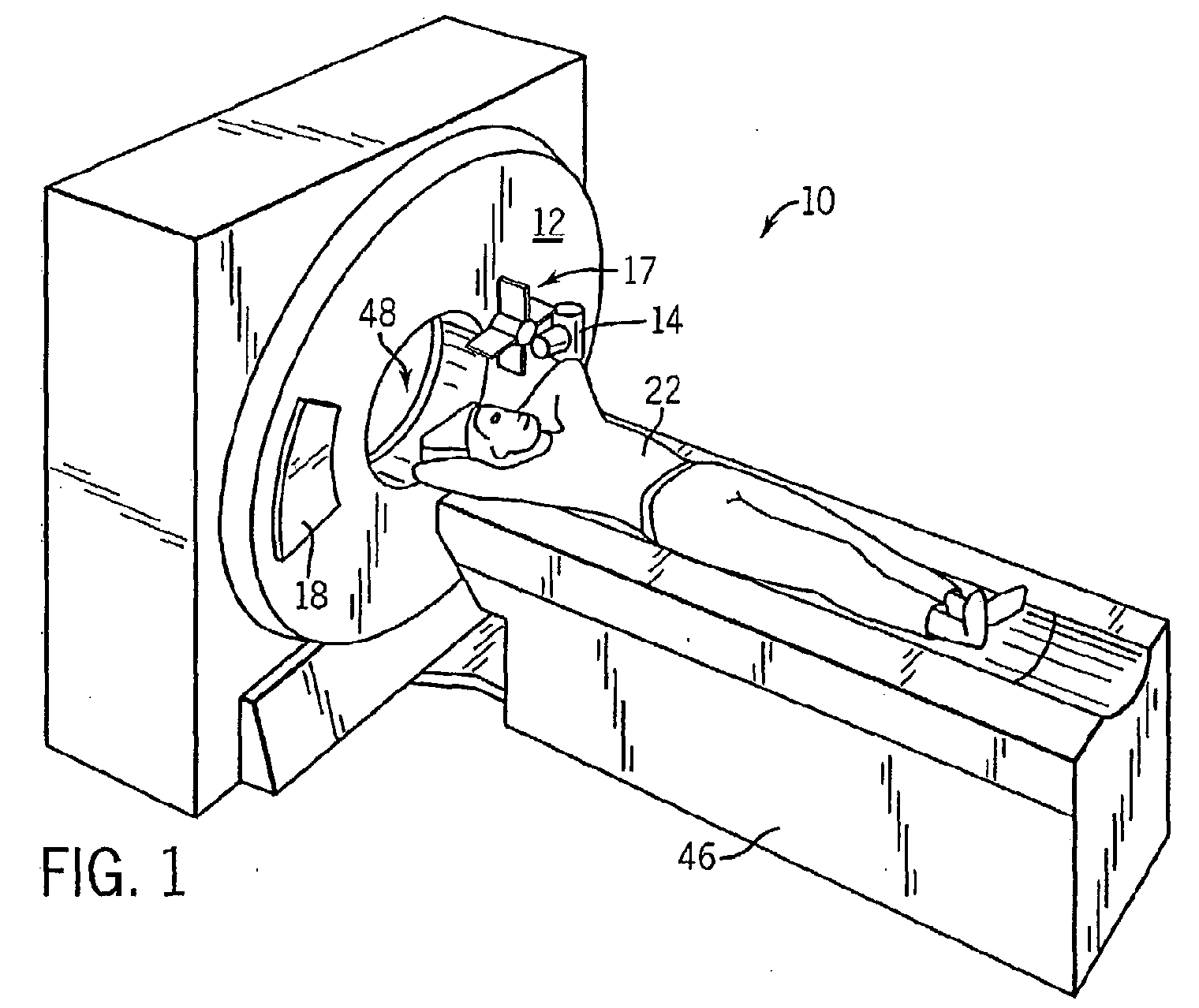
- Fig. 1 is a pictorial view of a CT imaging system.
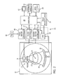
- Fig. 2 is a block schematic diagram of the system illustrated in Fig. 1.
- Fig. 3 is a perspective view of one embodiment of a CT system detector array.
- Fig. 4 is a perspective view of one embodiment of a detector.
- Fig. 5 is illustrative of various configurations of the detector in Fig. 4 in a four-slice mode.
- Fig. 6 is a perspective view of one embodiment of a filtering apparatus in accordance with the present invention.
- Fig. 7 illustrates positioning of each filter of the filtering apparatus as a function of energy applied to a high frequency electromagnetic energy projection source.
- Fig. 8 is a cross-sectional view of an alternate embodiment of a filtering apparatus in accordance with the present invention.
- Fig. 9 is a pictorial view of a CT system for use with a non-invasive package inspection system.
-
- The operating environment of the present invention is described with respect to a four-slice computed tomography (CT) system. However, it will be appreciated by those skilled in the art that the present invention is equally applicable for use with single-slice or other multi-slice configurations. Moreover, the present invention will be described with respect to the detection and conversion of x-rays. However, one skilled in the art will further appreciate, that the present invention is equally applicable for the detection and conversion of other high frequency electromagnetic energy. The present invention will be described with respect to a "third generation" CT scanner, but is equivalently applicable with other CT systems.
- Referring to Figs. 1 and 2, a computed tomography (CT)
imaging system 10 is shown as including agantry 12 representative of a "third generation" CT scanner.Gantry 12 has anx-ray source 14 that projects a beam ofx-rays 16 toward afiltering apparatus 17 and adetector array 18 on the opposite side of thegantry 12. Thefiltering apparatus 17 may include a pre-patient filter, a post-patient filter, or both. In Figs. 1 and 2, thefiltering apparatus 17 is shown as a pre-patient filter, as will be described more fully with respect to Figs. 6-8.Detector array 18 is formed by a plurality ofdetectors 20 which together sense the projected x-rays that pass through amedical patient 22. Eachdetector 20 produces an electrical signal that represents the intensity of an impinging x-ray beam and hence the attenuated beam as it passes through thepatient 22. During a scan to acquire x-ray projection data,gantry 12 and the components mounted thereon includingsource 14,filtering apparatus 17, anddetector array 18 rotate about a center ofrotation 24. - Rotation of
gantry 12 and the operation ofx-ray source 14 are governed by acontrol mechanism 26 ofCT system 10. As will be described below,control mechanism 26 includes afilter controller 27 that provides positioning signals to filteringapparatus 17.Control mechanism 26 also includes an x-ray controller 28 that provides power and timing signals to anx-ray source 14 and agantry motor controller 30 that controls the rotational speed and position ofgantry 12. A data acquisition system (DAS) 32 incontrol mechanism 26 samples analog data fromdetectors 20 and converts the data to digital signals for subsequent processing. Animage reconstructor 34 receives sampled and digitized x-ray data fromDAS 32 and performs high speed reconstruction. The reconstructed image is applied as an input to acomputer 36 which stores the image in amass storage device 38. -
Computer 36 also receives commands and scanning parameters from an operator viaconsole 40 that has a keyboard or other data entry module. An associateddisplay 42 allows the operator to observe the reconstructed image and other data fromcomputer 36. The operator supplied commands and parameters are used bycomputer 36 to provide control signals and information toDAS 32, x-ray controller 28 andgantry motor controller 30. In addition,computer 36 operates atable motor controller 44 which controls a motorized table 46 to positionpatient 22 andgantry 12. Particularly, table 46 moves portions ofpatient 22 through agantry opening 48. - As shown in Figs. 3 and 4,
detector array 18 includes a plurality ofphotodiodes 60 forming aphotodiode array 52 and a plurality ofscintillators 57 forming ascintillator array 56. A collimator (not shown) is positioned abovescintillator array 56 to collimate x-ray beams 16 before such beams impinge uponscintillator array 56. - In one embodiment, shown in Fig. 3,
detector array 18 includes 57detectors 20, eachdetector 20 having an array size of 16 x 16. As a result,array 18 has 16 rows and 912 columns (16 x 57 detectors) which allows 16 simultaneous slices of data to be collected with each rotation ofgantry 12. -
Switch arrays scintillator array 56 andDAS 32.Switch arrays respective photodiodes 60 and a number of output leads electrically connected toDAS 32 via a flexibleelectrical interface 84. Particularly, about one-half of photodiode outputs are electrically connected to switch 80 with the other one-half of photodiode outputs electrically connected to switch 82. Additionally, areflector material 59 is interstitially disposed between each scintillator 57 to reduce light spreading from adjacent scintillators. Eachdetector 20 is secured to adetector frame 77, Fig. 3, by mountingbrackets 79. -
Switch arrays arrays DAS 32. In one embodiment defined as a 16 slice mode, decoder enablesswitch arrays photodiode array 52 are activated, resulting in 16 simultaneous slices of data for processing byDAS 32. Of course, many other slice combinations are possible. For example, decoder may also select from other slice modes, including one, two, and four-slice modes. - As shown in Fig. 5, by transmitting the appropriate decoder instructions,
switch arrays photodiode array 52. Depending upon the specific configuration ofswitch arrays photodiodes 60 can be enabled, disabled, or combined so that the slice thickness may consist of one, two, three, or four rows ofscintillator array elements 57. Additional examples include, a single slice mode including one slice with slices ranging from 1.25 mm thick to 20 mm thick, and a two slice mode including two slices with slices ranging from 1.25 mm thick to 10 mm thick. Additional modes beyond those described are contemplated. - Referring now to Fig. 6, a four-
spoked filtering apparatus 17 is shown. While a four-spoked filtering apparatus will be described, the present invention is not so limiting and therefore a filtering apparatus with less than four filter spokes as well as a filtering apparatus with more than four filter spokes are contemplated and within the scope of the present invention.Filtering apparatus 17 includes ahub 86 having a number ofconnection ports 88. In this embodiment, aconnection port 88 is positioned every 90° around the hub.Hub 86 is shown as a cylinder but a spherical hub is also contemplated. In a three-spoked filtering apparatus, each connection port would be located every 120° along the hub. Connected tohub 86 at eachconnection port 88 is afilter 90. Eachfilter member 90 may be connected tohub 86 atconnection port 88 in a number of known manners. For example, filtering member 92-96 may be snap-fit, bolted, or integrated withhub 86 as a single integral body. In this embodiment, eachconnection port 86 includes a slot for receiving a filter but other receiving designs are contemplated. As will be described below, each filtering member 92-96 has a differing filtering power. That is, filteringmember 90 has a filtering power different from the filtering power offilter 94 and so forth. -
Hub 86 includes circuitry (not shown) that responds to electrical signals generated byfilter controller 27, Fig. 2, to position one of the filters 90-96 in a path of high frequency electromagnetic energy.Hub 86 is thereby caused to rotate filters 90-96 into the high frequency electromagnetic energy path synchronously with energization of the high frequency electromagneticenergy projection source 14 of Fig. 1. The synchronous relationship of filter position and source energization is best shown in Fig. 7. - Shown in Fig. 7 are three plots illustrating the position of each filter with respect to the kVp potential of the high frequency electromagnetic energy source. As shown, a first filter, such as
filter 90, is positioned in the path of high frequency electromagnetic energy when the high frequency electromagnetic energy source projects a burst of high frequency electromagnetic energy having a kVp potential A. The x-ray source then emits a second burst of x-rays having a kVp potential B and simultaneously therewithfilter 92 is positioned in the x-ray path. Thereafter, the x-ray source emits another burst of x-rays having a kVp potential C. Simultaneously therewith,filter 94 is rotated by the hub into the x-ray path. The x-ray source is then instructed to emit another burst of x-rays having a kVp potential D. When the x-ray source generates the burst of x-rays at potential D, the filter controller transmits a signal to the filtering apparatus to positionfilter 96 in the x-ray path. - Fig. 7 illustrates the positioning of each filter in the x-ray path depending upon the kVp potential of the beam of x-rays. However, the present invention does not require the sequential placement of each filter as described above. That is, depending upon the requirements of the
imaging protocol filter 96 may be positioned in the x-ray path afterfilter 90. Ultimately, the order by which the filters are positioned in the x-ray path is not limited to the sequential description provided above. - Referring now to Fig. 8, a
filtering apparatus 98 in accordance with another embodiment of the present invention is shown.Filtering apparatus 98 may be used with or independently offiltering apparatus 17 specifically described in Fig. 6. In the illustrated embodiment,filtering apparatus 98 includes a single filter comprising a number of filtering sections 100-106. Each filtering section 100-106 has a different filtering power. Therefore,filtering apparatus 98 may be used for multi-energy CT scanning.Filtering apparatus 98 is designed such that one section 100-106 is positioned in the x-ray path depending upon the kVp potential of the x-ray beam. For example, when the x-ray beam has a high kVppotential filtering section 100 may be positioned in the x-ray path. Whereas, when the x-ray beam has a lower kVppotential filtering section 106 is positioned within the x-ray path.Filtering apparatus 98 is shown as comprising four separate and distinct filtering sections. However, the present invention is not limited to only four sections and therefore a filtering apparatus with less than four sections or more than four sections is equivalently applicable with the present invention. - In an alternate embodiment of the present invention, the
filtering apparatus 98 shown in Fig. 8 is incorporated with the four-spoked filtering apparatus 17 illustrated in Fig. 6. With this embodiment, each filter 90-96 has a number of filtering sections similar to that shown in Fig. 8. As a result, the number of filtering combinations can be increased without requiring multiple filtering apparatuses. For example, in a four-spoked filtering apparatus wherein each filter has four filtering sections, a total of sixteen filtering combinations may be utilized in acquiring imaging data. - Referring now to Fig. 9, package/
baggage inspection system 100 includes arotatable gantry 102 having anopening 104 therein through which packages or pieces of baggage may pass. Therotatable gantry 102 houses a high frequencyelectromagnetic energy source 106 and afiltering apparatus 107, as well as adetector assembly 108.Filtering apparatus 107 is shown as being positioned between the source106 andobject 116. However,filtering apparatus 107 could be placed betweenobject 116 anddetector assembly 108. In another embodiment, a first filter is positioned pre-object and a second filter positioned post-object. Aconveyor system 110 is also provided and includes aconveyor belt 112 supported bystructure 114 to automatically and continuously pass packages orbaggage pieces 116 throughopening 104 to be scanned.Objects 116 are fed throughopening 104 byconveyor belt 112, imaging data is then acquired, and theconveyor belt 112 removes thepackages 116 from opening 104 in a controlled and continuous manner. As a result, postal inspectors, baggage handlers, and other security personnel may non-invasively inspect the contents ofpackages 116 for explosives, knives, guns, contraband, etc. by viewing the images on a display (not shown). - Therefore, in accordance with one embodiment of the present invention, a CT system comprises a rotatable gantry having an opening for receiving a subject to be scanned. The CT system further includes a high frequency electromagnetic energy source configured to project a number of high frequency electromagnetic energy beams towards the subject. A generator is also provided and configured to energize the high frequency electromagnetic energy source to at least a first energy state and a second energy state. The CT system also includes a number of high frequency electromagnetic energy filters positionable between the high frequency electromagnetic energy source and the subject. The number of high frequency electromagnetic energy filters includes at least a first filter and a second filter wherein the first filter is positioned between the high frequency electromagnetic energy source and the subject when the high frequency electromagnetic energy source is energized to the first energy state. The second filter is configured to be positioned between the high frequency electromagnetic energy source and the subject when the high frequency electromagnetic energy source is energized to the second energy state.
- In accordance with a further embodiment of the present invention, a controller is configured to acquire CT imaging data in more than one chromatic energy state. The controller has instructions to energize a high frequency electromagnetic energy source configured to project a high frequency electromagnetic energy beam toward a subject to be scanned to a first voltage potential. The controller has further instructions to position a first portion of a filtering apparatus between the subject and the high frequency electromagnetic energy source along a path of rotation during energization of the high frequency electromagnetic energy source to the first voltage potential. The controller also has instructions to energize the high frequency electromagnetic energy source to a second voltage potential. The controller is then instructed to position a second portion of the filtering apparatus between the subject and the high frequency electromagnetic energy source along the path of rotation during energization of the high frequency electromagnetic energy source to the second voltage potential.
- In accordance with a further embodiment of the present invention, a method of acquiring imaging data at more than one chromatic energy comprises the step of projecting a first beam of electromagnetic energy along a projection path toward a subject. The method further includes the step of positioning a first filter in the projection path during projection of the first beam. The method also includes projecting a second beam of electromagnetic energy along the projection path toward the subject and includes the step of positioning a second filter in the projection path during projection of the second beam of electromagnetic energy.
- In accordance with yet a further embodiment of the present invention, a computer readable storage medium has a computer program stored thereon. The computer program represents a set of instructions that when executed by a computer causes the computer to energize high frequency electromagnetic energy source to a first voltage to cause the high frequency electromagnetic energy source to project a first beam of electromagnetic energy toward the subject to be scanned. The computer is further caused to position a first filter between the high frequency electromagnetic energy source and the subject during energization of the high frequency electromagnetic energy source to the first voltage. The set of instructions further causes the computer to energize the high frequency electromagnetic energy source to a second voltage to cause the high frequency electromagnetic energy source to project a second beam of electromagnetic energy toward the subject and position a second filter between the electromagnetic energy source and the subject during energization of the high frequency electromagnetic energy source to the second voltage.
- In accordance with yet another embodiment of the present invention, a filtering apparatus for a radiation emitting imaging system is provided. The filtering apparatus includes a hub having a number of connection ports and a first filter connected to the hub at a first connection port and a second filter connected to the hub at a second connection port. The first filter is configured to have a first filtering power and the second filter is configured to have a second filtering power.
- For the sake of good order, various aspects of the invention are set out in the following clauses:-
- 1. A CT system (10) comprising:
- a rotatable gantry (12) having an opening (48) for receiving a subject (22) to be scanned;
- an HF electromagnetic energy source (14) configured to project a number of HF electromagnetic energy beams (16) toward the subject (22);
- a generator configured to energize the HF electromagnetic energy source (14) to at least a first energy state and a second energy state; and
- a number of HF electromagnetic energy filters (17) positional between the HF electromagnetic energy source (14) and the subject (22), the number of HF electromagnetic energy filters (17) including at least a first filter (90) and a second filter (92) wherein the first filter (90) is positioned between the HF electromagnetic energy source (14) and the subject (22) when the HF electromagnetic energy source (14) is energized to the first energy state and the second filter (92) is positioned between the HF electromagnetic energy source (14) and the subject (22) when the HF electromagnetic energy source (14) is energized to the second energy state.
- 2. The CT system (10) of
clause 1 wherein the HF electromagnetic energy source (14) and the number of HF electromagnetic energy filters (17) are rotatable about the subject (22). - 3. The CT system (10) of
clause 1 further comprising: - a set of HF electromagnetic energy detectors (20) configured to generate a set of electrical signals indicative of HF electromagnetic energy attenuated by the subject (22);
- a DAS (32) configured to receive the set of electrical signals; and
- an image reconstructor (34) connected to the DAS (32) and configured to reconstruct an image of the subject (22) from the electrical signals received by the DAS (32).
- 4. The CT system (10) of
clause 1 further comprising a movable table (46) configured to position the subject (22) within the opening (48). - 5. The CT system (10) of
clause 4 incorporated into a medical imaging device and wherein the subject (22) is a medical patient. - 6. The CT system (10) of
clause 4 wherein the movable table (46) is configured to convey articles through the opening wherein the articles (116) include pieces of luggage/baggage and packages. - 7. The CT system (10) of clause 6 incorporated into at least one of an airport inspection apparatus (100) and a postal inspection apparatus (100).
- 8. A controller (26) configured to acquire CT imaging data at more than
one chromatic energy state, the controller having instructions to:
- energize an HF electromagnetic energy source (14) configured to project an HF electromagnetic energy beam (16) toward a subject (22) to be scanned to a first voltage potential;
- position a first portion (90) of a filtering apparatus (17) between the subject (22) and the HF electromagnetic energy source (14) along a path of rotation (24) during energization of the HF electromagnetic energy source (14) to the first voltage potential;
- energize the HF electromagnetic energy source (14) to a second voltage potential; and
- position a second portion (52) of the filtering apparatus (17) between the subject (22) and the HF electromagnetic energy source (14) along the path of rotation (24) during energization of the HF electromagnetic energy source (14) to the second voltage potential.
- 9. The controller (26) of clause 8 having further instructions to energize the HF electromagnetic energy source (14) such that a burst of HF electromagnetic energy (16) is projected toward the subject (22).
- 10. The controller (26) of clause 8 wherein the filtering apparatus (17) includes a single filter (98) and wherein the first portion (106) has a filtering power difference than a filtering power of the second portion (102).
- 11. The controller (26) of clause 8 wherein the filtering apparatus (17)
includes a first filter (90) and a second filter (92), the controller having further
instructions to:
- position the first filter (90) between the subject (22) and the HF electromagnetic energy source (14) along the path of rotation (24) during energization of the HF electromagnetic energy source (14) to the first voltage potential; and
- position the second filter (92) between the subject (22) and the HF electromagnetic energy source (14) along the path of rotation (24) during energization of the HF electromagnetic energy source (14) to the second voltage potential.
- 12. The controller (26) of clause 11 having further instructions to:
- position the first filter (96) between the subject (22) and a portion of the HF electromagnetic energy source (14) along the path of rotation during energization of the HF electromagnetic energy source (14) to the first voltage potential; and
- position the second filter (92) between the subject (22) and the HF electromagnetic energy source (14) along another path of rotation during energization of the HF electromagnetic energy source (14) to the second voltage potential.
- 13. The controller (26) of clause 9 incorporated into a medical imaging apparatus (10) configured to acquire medical diagnostic data of a medical patient (22).
- 14. The controller (26) of clause 9 incorporated into a non-invasive parcel inspection apparatus (106) configured to non-invasively determine contents within a parcel (116).
- 15. The controller (26) of
clause 14 wherein the non-invasive parcel inspection apparatus (100) incorporated into at least one of a postal inspection system and an airport baggage inspection system. - 16. A method of acquiring imaging data at more than one chromatic energy
comprising the steps of:
- projecting a first beam of electromagnetic energy (16) along a projection path toward a subject (22) to be scanned;
- positioning a first filter (90) in the projection path during projection of the first beam (16);
- projecting a second beam (16) of electromagnetic energy along the projection path toward the subject (22); and
- positioning a second filter (92) in the projection path during projection of the second beam (16).
- 17. The method of
clause 16 further comprising the steps of: - energizing an HF electromagnetic energy source (14) to a first voltage to generate the first beam of electromagnetic energy (16);
- rotating the first filter (90) along a path of rotation (24) such that the first filter (90) is in the projection path (24) during energization of the HF electromagnetic energy source (14) to the first voltage;
- energizing the HF electromagnetic source (14) to a second voltage to generate the second beam of electromagnetic energy (16); and
- rotating the second filter (92) along the path of rotation (24) such that the second filter (92) is in the projection path during energization of the HF electromagnetic energy source (14) to the second voltage.
- 18. The method of
clause 16 further comprising the step of acquiring imaging data with a first HF electromagnetic energy beam (16) having a signal strength substantially equal to a signal strength of a second HF electromagnetic energy beam (16). - 19. A computer readable storage medium having a computer program
stored thereon and representing a set of instructions that when executed by a
computer (26) causes the computer (26) to:
- energize an HF electromagnetic energy source (14) to a first voltage to cause the HF electromagnetic energy source (14) to project a first beam of electromagnetic energy (16) toward a subject (22) to be scanned;
- position a first filter (90) between the HF electromagnetic energy source (14) and the subject (22) during energization of the HF electromagnetic energy source (14) to the first voltage;
- energize the HF electromagnetic energy source (14) to a second voltage to cause the HF electromagnetic energy source (14) to project a second beam of electromagnetic energy (16) toward the subject (22); and
- position a second filter (92) between the HF electromagnetic energy source (14) and the subject (22) during energization of the HF electromagnetic energy source (14) to the second voltage.
- 20. The computer readable storage medium of clause 19 wherein the set of instructions further causes the computer (26) to rotate the first filter (90) and the second filter (92) about the subject (22) along a common path of rotation (24).
- 21. The computer readable storage medium of clause 19 wherein the set of instructions further causes the computer (26) to rotate the first filter (90) about the subject (22) along a first path of rotation and rotate the second filter (92) about the subject (22) along a second path of rotation.
- 22. The computer readable storage medium of clause 19 incorporated into a medical imaging apparatus (10) configured to acquire diagnostic imaging data of a medical patient (22).
- 23. The computer readable storage medium of clause 19 incorporated into a non-invasive parcel inspection apparatus (100) including at least one of a postal inspection apparatus and a baggage inspection apparatus.
- 24. A filtering apparatus (17) for a radiation emitting imaging system, the
filtering apparatus comprising:
- a hub (86) having a number of connection ports (88);
- a first filter (96) connected to the hub (86) at a first connection port (88), the first filter (90) having a first filtering power (166); and
- a second filter (92) connected to the hub (86) at a second connection port (88), the second filter (92) having a second filtering power (102).
- 25. The filtering apparatus (17) of
clause 24 wherein the first connection port (88) is positioned 90° along the hub (86) from the second connection port (88). - 26. The filtering apparatus (17) of
clause 24 wherein the hub (86) is configured to rotate the first filter (90) into a path of HF electromagnetic energy (16) when an HF electromagnetic energy source (14) is energized to a first voltage A and rotate the second filter (92) into the path of HF energy (16) when the HF electromagnetic energy projection source (14) is energized to a second voltage B. - 27. The filtering apparatus (17) of
clause 24 further comprising a third filter (94) connected to the hub (86) at a third connection port (88) and a fourth filter (96) connected to the hub (86) at a fourth connection port (88), the third (94) and the fourth (96) filters having differing filtering powers (104, 106) and the third connection port (88) being positioned 90° along the hub (86) from the fourth connection port (88). -
Claims (10)
- A CT system (10) comprising:a rotatable gantry (12) having an opening (48) for receiving a subject (22) to be scanned;an HF electromagnetic energy source (14) configured to project a number of HF electromagnetic energy beams (16) toward the subject (22);a generator configured to energize the HF electromagnetic energy source (14) to at least a first energy state and a second energy state; anda number of HF electromagnetic energy filters (17) positional between the HF electromagnetic energy source (14) and the subject (22), the number of HF electromagnetic energy filters (17) including at least a first filter (90) and a second filter (92) wherein the first filter (90) is positioned between the HF electromagnetic energy source (14) and the subject (22) when the HF electromagnetic energy source (14) is energized to the first energy state and the second filter (92) is positioned between the HF electromagnetic energy source (14) and the subject (22) when the HF electromagnetic energy source (14) is energized to the second energy state.
- The CT system (10) of claim 1 wherein the HF electromagnetic energy source (14) and the number of HF electromagnetic energy filters (17) are rotatable about the subject (22).
- A controller (26) configured to acquire CT imaging data at more than one chromatic energy state, the controller having instructions to:energize an HF electromagnetic energy source (14) configured to project an HF electromagnetic energy beam (16) toward a subject (22) to be scanned to a first voltage potential;position a first portion (90) of a filtering apparatus (17) between the subject (22) and the HF electromagnetic energy source (14) along a path of rotation (24) during energization of the HF electromagnetic energy source (14) to the first voltage potential;energize the HF electromagnetic energy source (14) to a second voltage potential; andposition a second portion (52) of the filtering apparatus (17) between the subject (22) and the HF electromagnetic energy source (14) along the path of rotation (24) during energization of the HF electromagnetic energy source (14) to the second voltage potential.
- The controller (26) of claim 3 having further instructions to energize the HF electromagnetic energy source (14) such that a burst of HF electromagnetic energy (16) is projected toward the subject (22).
- A method of acquiring imaging data at more than one chromatic energy comprising the steps of:projecting a first beam of electromagnetic energy (16) along a projection path toward a subject (22) to be scanned;positioning a first filter (90) in the projection path during projection of the first beam (16);projecting a second beam (16) of electromagnetic energy along the projection path toward the subject (22); andpositioning a second filter (92) in the projection path during projection of the second beam (16).
- The method of claim 5 further comprising the steps of:energizing an HF electromagnetic energy source (14) to a first voltage to generate the first beam of electromagnetic energy (16);rotating the first filter (90) along a path of rotation (24) such that the first filter (90) is in the projection path (24) during energization of the HF electromagnetic energy source (14) to the first voltage;energizing the HF electromagnetic source (14) to a second voltage to generate the second beam of electromagnetic energy (16); androtating the second filter (92) along the path of rotation (24) such that the second filter (92) is in the projection path during energization of the HF electromagnetic energy source (14) to the second voltage.
- A computer readable storage medium having a computer program stored thereon and representing a set of instructions that when executed by a computer (26) causes the computer (26) to:energize an HF electromagnetic energy source (14) to a first voltage to cause the HF electromagnetic energy source (14) to project a first beam of electromagnetic energy (16) toward a subject (22) to be scanned;position a first filter (90) between the HF electromagnetic energy source (14) and the subject (22) during energization of the HF electromagnetic energy source (14) to the first voltage;energize the HF electromagnetic energy source (14) to a second voltage to cause the HF electromagnetic energy source (14) to project a second beam of electromagnetic energy (16) toward the subject (22); andposition a second filter (92) between the HF electromagnetic energy source (14) and the subject (22) during energization of the HF electromagnetic energy source (14) to the second voltage.
- The computer readable storage medium of claim 7 wherein the set of instructions further causes the computer (26) to rotate the first filter (90) and the second filter (92) about the subject (22) along a common path of rotation (24).
- A filtering apparatus (17) for a radiation emitting imaging system, the filtering apparatus comprising:a hub (86) having a number of connection ports (88);a first filter (96) connected to the hub (86) at a first connection port (88), the first filter (90) having a first filtering power (166); anda second filter (92) connected to the hub (86) at a second connection port (88), the second filter (92) having a second filtering power (102).
- The filtering apparatus (17) of claim 9 wherein the first connection port (88) is positioned 90° along the hub (86) from the second connection port (88).
Applications Claiming Priority (2)
| Application Number | Priority Date | Filing Date | Title |
|---|---|---|---|
| US63366 | 2002-04-16 | ||
| US10/063,366 US7636413B2 (en) | 2002-04-16 | 2002-04-16 | Method and apparatus of multi-energy imaging |
Publications (2)
| Publication Number | Publication Date |
|---|---|
| EP1355321A2 true EP1355321A2 (en) | 2003-10-22 |
| EP1355321A3 EP1355321A3 (en) | 2010-08-11 |
Family
ID=28673458
Family Applications (1)
| Application Number | Title | Priority Date | Filing Date |
|---|---|---|---|
| EP03252379A Withdrawn EP1355321A3 (en) | 2002-04-16 | 2003-04-15 | Method and apparatus of multi-energy imaging |
Country Status (4)
| Country | Link |
|---|---|
| US (3) | US7636413B2 (en) |
| EP (1) | EP1355321A3 (en) |
| JP (1) | JP4478400B2 (en) |
| IL (1) | IL155170A (en) |
Cited By (4)
| Publication number | Priority date | Publication date | Assignee | Title |
|---|---|---|---|---|
| US7086780B2 (en) | 2004-05-20 | 2006-08-08 | General Electric Company | Methods for spectrally calibrating CT imaging apparatus detectors |
| DE102007020545A1 (en) * | 2006-05-19 | 2007-12-06 | Tsinghua University | Detector matrix and device for its use |
| US7391844B2 (en) | 2005-01-14 | 2008-06-24 | General Electric Company | Method and apparatus for correcting for beam hardening in CT images |
| WO2010015960A1 (en) | 2008-08-08 | 2010-02-11 | Koninklijke Philips Electronics, N.V. | Voltage modulated x-ray tube |
Families Citing this family (51)
| Publication number | Priority date | Publication date | Assignee | Title |
|---|---|---|---|---|
| US7636413B2 (en) * | 2002-04-16 | 2009-12-22 | General Electric Company | Method and apparatus of multi-energy imaging |
| US20030199757A1 (en) * | 2002-04-22 | 2003-10-23 | Toth Thomas L. | Method and apparatus of modulating radiation filtering during radiographic imaging |
| US7046756B2 (en) * | 2003-05-20 | 2006-05-16 | General Electric Company | Rotatable filter for a pre-subject CT collimator having multiple filtering profiles |
| US6968030B2 (en) * | 2003-05-20 | 2005-11-22 | General Electric Company | Method and apparatus for presenting multiple pre-subject filtering profiles during CT data acquisition |
| US7120222B2 (en) * | 2003-06-05 | 2006-10-10 | General Electric Company | CT imaging system with multiple peak x-ray source |
| US7076029B2 (en) * | 2003-10-27 | 2006-07-11 | General Electric Company | Method and apparatus of radiographic imaging with an energy beam tailored for a subject to be scanned |
| US7260171B1 (en) * | 2004-10-25 | 2007-08-21 | General Electric Company | Apparatus for acquisition of CT data with penumbra attenuation calibration |
| US7660488B2 (en) | 2004-11-04 | 2010-02-09 | Dr Systems, Inc. | Systems and methods for viewing medical images |
| US7920152B2 (en) | 2004-11-04 | 2011-04-05 | Dr Systems, Inc. | Systems and methods for viewing medical 3D imaging volumes |
| US7970625B2 (en) | 2004-11-04 | 2011-06-28 | Dr Systems, Inc. | Systems and methods for retrieval of medical data |
| US7885440B2 (en) | 2004-11-04 | 2011-02-08 | Dr Systems, Inc. | Systems and methods for interleaving series of medical images |
| US7787672B2 (en) | 2004-11-04 | 2010-08-31 | Dr Systems, Inc. | Systems and methods for matching, naming, and displaying medical images |
| CN101074937B (en) * | 2006-05-19 | 2010-09-08 | 清华大学 | Energy spectrum modulation device, method and device for identifying materials, and image processing method |
| US7953614B1 (en) | 2006-11-22 | 2011-05-31 | Dr Systems, Inc. | Smart placement rules |
| CN101557762B (en) * | 2006-12-15 | 2012-06-27 | 皇家飞利浦电子股份有限公司 | Spectrally resolving x-ray imaging device |
| WO2009014166A1 (en) * | 2007-07-25 | 2009-01-29 | Hitachi Medical Corporation | X-ray ct device |
| DE102008056891B4 (en) * | 2008-11-12 | 2012-04-12 | Siemens Aktiengesellschaft | A computed tomography device for performing a spiral scan and method of controlling a computed tomography device |
| US8380533B2 (en) | 2008-11-19 | 2013-02-19 | DR Systems Inc. | System and method of providing dynamic and customizable medical examination forms |
| DE102009010501A1 (en) * | 2009-02-25 | 2010-09-09 | Siemens Aktiengesellschaft | Method for noise reduction of CT image data and image processing system |
| JP2011067333A (en) | 2009-09-25 | 2011-04-07 | Fujifilm Corp | Radiation imaging apparatus and imaging control device |
| US8712120B1 (en) | 2009-09-28 | 2014-04-29 | Dr Systems, Inc. | Rules-based approach to transferring and/or viewing medical images |
| US8548118B2 (en) * | 2009-12-21 | 2013-10-01 | General Electric Company | Apparatus and method for spectral projection imaging with fast KV switching |
| US8311182B2 (en) | 2010-09-22 | 2012-11-13 | General Electric Company | System and method of notch filtration for dual energy CT |
| DE102011004742B4 (en) | 2011-02-25 | 2015-02-12 | Siemens Aktiengesellschaft | Filter for an X-ray device and X-ray device |
| JP2013005854A (en) * | 2011-06-23 | 2013-01-10 | Toshiba Corp | X-ray ct apparatus |
| US9092551B1 (en) | 2011-08-11 | 2015-07-28 | D.R. Systems, Inc. | Dynamic montage reconstruction |
| US9325913B2 (en) | 2011-12-28 | 2016-04-26 | General Electric Company | Radiation detector for use in sequential image acquisition |
| DE102012219051A1 (en) * | 2012-10-18 | 2014-04-24 | Klinikum Der Universität München | Selection of a radiation form filter |
| US9495604B1 (en) | 2013-01-09 | 2016-11-15 | D.R. Systems, Inc. | Intelligent management of computerized advanced processing |
| EP2987454A4 (en) * | 2013-04-16 | 2016-09-21 | Toshiba Medical Sys Corp | X-RAY TOMODENSITOMETER |
| US20150036792A1 (en) * | 2013-08-01 | 2015-02-05 | Korea Advanced Institute Of Science And Technology | Computed tomography apparatus, and method of generating image by using computed tomography apparatus |
| JP6266284B2 (en) * | 2013-09-19 | 2018-01-24 | 東芝メディカルシステムズ株式会社 | X-ray diagnostic equipment |
| DE102014203465B4 (en) * | 2014-02-26 | 2026-05-07 | Siemens Healthineers Ag | Selection of a radiation shape filter from a plurality of radiation shape filters |
| JP2015180859A (en) * | 2014-03-05 | 2015-10-15 | 株式会社東芝 | Photon counting CT system |
| JP6529858B2 (en) * | 2014-08-20 | 2019-06-12 | キヤノンメディカルシステムズ株式会社 | X-ray CT apparatus and X-ray detector |
| US9991014B1 (en) * | 2014-09-23 | 2018-06-05 | Daniel Gelbart | Fast positionable X-ray filter |
| US20170039321A1 (en) | 2015-04-30 | 2017-02-09 | D.R. Systems, Inc. | Database systems and interactive user interfaces for dynamic interaction with, and sorting of, digital medical image data |
| JP7015781B2 (en) * | 2015-07-24 | 2022-02-03 | フォト・ダイアグノスティック・システムズ,インコーポレイテッド | Methods and Instruments for Performing Multiple Energy (Including Dual Energy) Computed Tomography (CT) Imaging |
| DE102015226489B4 (en) * | 2015-12-22 | 2024-05-16 | Siemens Healthineers Ag | X-ray system and method for image reconstruction |
| US9822509B1 (en) * | 2016-05-02 | 2017-11-21 | Caterpillar Inc. | Method of controlling machines at a worksite |
| US10573030B2 (en) | 2017-04-07 | 2020-02-25 | Photo Diagnostic Systems, Inc. | Method for artifact reduction using monoenergetic data in computed tomography |
| CN110574124A (en) * | 2017-04-27 | 2019-12-13 | 美敦力导航股份有限公司 | Filter system and method for imaging a subject |
| US10806413B2 (en) | 2017-04-27 | 2020-10-20 | Medtronic Navigation, Inc. | Filter system and method for imaging a subject |
| US10849576B2 (en) | 2017-04-27 | 2020-12-01 | Medtronic Navigation, Inc. | Filter system and method for imaging a subject |
| US10682103B2 (en) | 2017-04-27 | 2020-06-16 | Medtronic Navigation, Inc. | Filter system and method for imaging a subject |
| DE102018204517B3 (en) * | 2018-03-23 | 2019-09-26 | Siemens Healthcare Gmbh | Method of imaging by means of a computed tomography device and computed tomography device |
| US10888294B2 (en) | 2018-12-27 | 2021-01-12 | Medtronic Navigation, Inc. | System and method for imaging a subject |
| US10881371B2 (en) | 2018-12-27 | 2021-01-05 | Medtronic Navigation, Inc. | System and method for imaging a subject |
| US11071507B2 (en) | 2018-12-27 | 2021-07-27 | Medtronic Navigation, Inc. | System and method for imaging a subject |
| JP7504819B2 (en) * | 2021-02-18 | 2024-06-24 | 富士フイルム株式会社 | IMAGING CONTROL DEVICE, RADIOLOGICAL IMAGING SYSTEM, IMAGING CONTROL METHOD, AND IMAGING CONTROL PROGRAM |
| US12133754B2 (en) * | 2022-04-15 | 2024-11-05 | Wisconsin Alumni Research Foundation | System and method for simultaneous acquisition of contrast dynamics and anatomical images |
Citations (1)
| Publication number | Priority date | Publication date | Assignee | Title |
|---|---|---|---|---|
| US5838758A (en) * | 1990-08-10 | 1998-11-17 | Vivid Technologies | Device and method for inspection of baggage and other objects |
Family Cites Families (29)
| Publication number | Priority date | Publication date | Assignee | Title |
|---|---|---|---|---|
| US4017192A (en) | 1975-02-06 | 1977-04-12 | Neotec Corporation | Optical analysis of biomedical specimens |
| US4307726A (en) * | 1978-04-24 | 1981-12-29 | Paulson James C | Diagnostic evaluation, measurement, and analysis of functional activity in body organs that utilize transmembrane ion polarization and depolarization |
| US4686695A (en) * | 1979-02-05 | 1987-08-11 | Board Of Trustees Of The Leland Stanford Junior University | Scanned x-ray selective imaging system |
| US4399550A (en) * | 1981-02-27 | 1983-08-16 | General Electric Company | Spinning filter for X-ray apparatus |
| US4598366A (en) * | 1982-11-12 | 1986-07-01 | Schlumberger Technology Corporation | Diffraction tomography systems and methods with arbitrary source and detector array surfaces |
| US4562540A (en) * | 1982-11-12 | 1985-12-31 | Schlumberger Technology Corporation | Diffraction tomography system and methods |
| US4780897A (en) * | 1986-05-06 | 1988-10-25 | General Electric Company | Dual energy imaging with kinestatic charge detector |
| US4963746A (en) * | 1986-11-25 | 1990-10-16 | Picker International, Inc. | Split energy level radiation detection |
| US5262946A (en) * | 1988-10-20 | 1993-11-16 | Picker International, Inc. | Dynamic volume scanning for CT scanners |
| US4975933A (en) * | 1990-03-26 | 1990-12-04 | General Electric Company | Bow-tie X-ray filter assembly for dual energy tomography |
| US5081660A (en) * | 1990-06-06 | 1992-01-14 | Yokio Fujisaki | High resolution x-ray imaging system with energy fluctuation restricting filters |
| US5485492A (en) * | 1992-03-31 | 1996-01-16 | Lunar Corporation | Reduced field-of-view CT system for imaging compact embedded structures |
| US5430787A (en) * | 1992-12-03 | 1995-07-04 | The United States Of America As Represented By The Secretary Of Commerce | Compton scattering tomography |
| US5371543A (en) * | 1993-03-03 | 1994-12-06 | Texas Instruments Incorporated | Monolithic color wheel |
| JPH0866781A (en) | 1994-08-30 | 1996-03-12 | Mitsubishi Electric Corp | Excimer laser beam irradiation device |
| DE69622759T2 (en) * | 1995-11-22 | 2003-03-20 | Picker International Inc., Cleveland | SCATTERING FILTER FOR EMISSION TOMOGRAPHY |
| US5771269A (en) * | 1995-12-29 | 1998-06-23 | Advanced Optical Technologies, Inc. | Apparatus and method for removing scatter from an x-ray image |
| US5661774A (en) * | 1996-06-27 | 1997-08-26 | Analogic Corporation | Dual energy power supply |
| US5917877A (en) * | 1997-09-05 | 1999-06-29 | Cyberlogic, Inc. | Plain x-ray bone densitometry apparatus and method |
| US6081322A (en) * | 1997-10-16 | 2000-06-27 | Research Foundation Of State Of New York | NIR clinical opti-scan system |
| US6236709B1 (en) * | 1998-05-04 | 2001-05-22 | Ensco, Inc. | Continuous high speed tomographic imaging system and method |
| US6226352B1 (en) * | 1998-09-08 | 2001-05-01 | Veritas Pharmaceuticals, Inc. | System and method for radiographic imaging of tissue |
| JP2001087254A (en) | 1999-09-17 | 2001-04-03 | Hitachi Medical Corp | X-ray image diagnostic system |
| US6285740B1 (en) * | 1999-10-13 | 2001-09-04 | The United States Of America As Represented By The Secretary Of The Navy | Dual energy x-ray densitometry apparatus and method using single x-ray pulse |
| JP2002102217A (en) | 2000-09-28 | 2002-04-09 | Ge Medical Systems Global Technology Co Llc | X-ray ct system, gantory apparatus, console terminal and controlling method therefor, and storage medium |
| US6650730B2 (en) * | 2001-01-23 | 2003-11-18 | Fartech, Inc. | Filter assembly for X-ray filter system for medical imaging contrast enhancement |
| DE10143131B4 (en) * | 2001-09-03 | 2006-03-09 | Siemens Ag | Method for determining density and atomic number distributions in radiographic examination methods |
| US7636413B2 (en) * | 2002-04-16 | 2009-12-22 | General Electric Company | Method and apparatus of multi-energy imaging |
| US6950493B2 (en) * | 2003-06-25 | 2005-09-27 | Besson Guy M | Dynamic multi-spectral CT imaging |
-
2002
- 2002-04-16 US US10/063,366 patent/US7636413B2/en not_active Expired - Lifetime
-
2003
- 2003-03-31 IL IL155170A patent/IL155170A/en not_active IP Right Cessation
- 2003-04-15 EP EP03252379A patent/EP1355321A3/en not_active Withdrawn
- 2003-04-15 JP JP2003109864A patent/JP4478400B2/en not_active Expired - Fee Related
-
2006
- 2006-08-21 US US11/465,947 patent/US7688936B2/en not_active Expired - Fee Related
- 2006-08-21 US US11/465,908 patent/US7688935B2/en not_active Expired - Fee Related
Patent Citations (1)
| Publication number | Priority date | Publication date | Assignee | Title |
|---|---|---|---|---|
| US5838758A (en) * | 1990-08-10 | 1998-11-17 | Vivid Technologies | Device and method for inspection of baggage and other objects |
Cited By (6)
| Publication number | Priority date | Publication date | Assignee | Title |
|---|---|---|---|---|
| US7086780B2 (en) | 2004-05-20 | 2006-08-08 | General Electric Company | Methods for spectrally calibrating CT imaging apparatus detectors |
| US7391844B2 (en) | 2005-01-14 | 2008-06-24 | General Electric Company | Method and apparatus for correcting for beam hardening in CT images |
| DE102007020545A1 (en) * | 2006-05-19 | 2007-12-06 | Tsinghua University | Detector matrix and device for its use |
| US7724869B2 (en) | 2006-05-19 | 2010-05-25 | Tsinghua University | Detector array and device using the same |
| WO2010015960A1 (en) | 2008-08-08 | 2010-02-11 | Koninklijke Philips Electronics, N.V. | Voltage modulated x-ray tube |
| US8755488B2 (en) | 2008-08-08 | 2014-06-17 | Koninklijke Philips N.V. | Voltage modulated x-ray tube |
Also Published As
| Publication number | Publication date |
|---|---|
| IL155170A (en) | 2011-06-30 |
| IL155170A0 (en) | 2003-10-31 |
| US7688936B2 (en) | 2010-03-30 |
| US7688935B2 (en) | 2010-03-30 |
| US7636413B2 (en) | 2009-12-22 |
| JP4478400B2 (en) | 2010-06-09 |
| US20070078336A1 (en) | 2007-04-05 |
| US20060280282A1 (en) | 2006-12-14 |
| US20030195416A1 (en) | 2003-10-16 |
| JP2003325504A (en) | 2003-11-18 |
| EP1355321A3 (en) | 2010-08-11 |
Similar Documents
| Publication | Publication Date | Title |
|---|---|---|
| US7688935B2 (en) | Method and apparatus of multi-energy imaging | |
| US7088799B2 (en) | Method and apparatus for presenting multiple pre-subject filtering profiles during CT data acquisition | |
| US7046756B2 (en) | Rotatable filter for a pre-subject CT collimator having multiple filtering profiles | |
| US6459755B1 (en) | Method and apparatus for administering low dose CT scans | |
| US7177387B2 (en) | Self-aligning scintillator-collimator assembly | |
| US6647095B2 (en) | Method and apparatus for optimizing dosage to scan subject | |
| JP6018748B2 (en) | CT imaging system | |
| JP5897890B2 (en) | Stacked flat panel X-ray detector assembly and CT imaging system comprising the detector assembly | |
| EP2438864B1 (en) | Multi-faceted tileable detector for volumetric computed tomography imaging | |
| US7428292B2 (en) | Method and system for CT imaging using multi-spot emission sources | |
| US7403590B2 (en) | CT detector photodiode having multiple charge storage devices | |
| US6654443B1 (en) | Thermal sensing detector cell for a computed tomography system and method of manufacturing same | |
| US6907101B2 (en) | CT detector with integrated air gap | |
| US6947517B2 (en) | Scintillator array having a reflector with integrated air gaps | |
| EP1338248A2 (en) | Method and apparatus of CT imaging with voltage modulation | |
| US7388940B1 (en) | Architectures for cardiac CT based on area x-ray sources | |
| US20060043305A1 (en) | Ct detector having a segmented optical coupler and method of manufacturing same | |
| US20030161437A1 (en) | Fiber optic scintillator with optical gain for a computed tomography system and method of manufacturing same | |
| JP2012125568A (en) | Stacked x-ray detector assembly and method of making same | |
| WO2009120417A1 (en) | System and method of fast switching for spectral imaging | |
| US20070086565A1 (en) | Focally aligned CT detector | |
| JP2008224302A (en) | Focally-aligned ct detector |
Legal Events
| Date | Code | Title | Description |
|---|---|---|---|
| PUAI | Public reference made under article 153(3) epc to a published international application that has entered the european phase |
Free format text: ORIGINAL CODE: 0009012 |
|
| AK | Designated contracting states |
Kind code of ref document: A2 Designated state(s): AT BE BG CH CY CZ DE DK EE ES FI FR GB GR HU IE IT LI LU MC NL PT RO SE SI SK TR |
|
| AX | Request for extension of the european patent |
Extension state: AL LT LV MK |
|
| PUAL | Search report despatched |
Free format text: ORIGINAL CODE: 0009013 |
|
| AK | Designated contracting states |
Kind code of ref document: A3 Designated state(s): AT BE BG CH CY CZ DE DK EE ES FI FR GB GR HU IE IT LI LU MC NL PT RO SE SI SK TR |
|
| AX | Request for extension of the european patent |
Extension state: AL LT LV MK |
|
| 17P | Request for examination filed |
Effective date: 20110211 |
|
| 17Q | First examination report despatched |
Effective date: 20110302 |
|
| AKX | Designation fees paid |
Designated state(s): DE |
|
| STAA | Information on the status of an ep patent application or granted ep patent |
Free format text: STATUS: THE APPLICATION IS DEEMED TO BE WITHDRAWN |
|
| 18D | Application deemed to be withdrawn |
Effective date: 20160823 |