EP1355305A2 - Controller and control method for information recording and reproducing device - Google Patents
Controller and control method for information recording and reproducing device Download PDFInfo
- Publication number
- EP1355305A2 EP1355305A2 EP02021287A EP02021287A EP1355305A2 EP 1355305 A2 EP1355305 A2 EP 1355305A2 EP 02021287 A EP02021287 A EP 02021287A EP 02021287 A EP02021287 A EP 02021287A EP 1355305 A2 EP1355305 A2 EP 1355305A2
- Authority
- EP
- European Patent Office
- Prior art keywords
- information recording
- vehicle
- reproducing device
- disk
- spindle motor
- Prior art date
- Legal status (The legal status is an assumption and is not a legal conclusion. Google has not performed a legal analysis and makes no representation as to the accuracy of the status listed.)
- Granted
Links
Images



Classifications
-
- G—PHYSICS
- G11—INFORMATION STORAGE
- G11B—INFORMATION STORAGE BASED ON RELATIVE MOVEMENT BETWEEN RECORD CARRIER AND TRANSDUCER
- G11B19/00—Driving, starting, stopping record carriers not specifically of filamentary or web form, or of supports therefor; Control thereof; Control of operating function ; Driving both disc and head
- G11B19/20—Driving; Starting; Stopping; Control thereof
-
- G—PHYSICS
- G11—INFORMATION STORAGE
- G11B—INFORMATION STORAGE BASED ON RELATIVE MOVEMENT BETWEEN RECORD CARRIER AND TRANSDUCER
- G11B19/00—Driving, starting, stopping record carriers not specifically of filamentary or web form, or of supports therefor; Control thereof; Control of operating function ; Driving both disc and head
- G11B19/02—Control of operating function, e.g. switching from recording to reproducing
- G11B19/04—Arrangements for preventing, inhibiting, or warning against double recording on the same blank or against other recording or reproducing malfunctions
Definitions
- the Invention relates to a controller for an information recording and reproducing device and a control method for the information recording and reproducing device in the case where the information recording and reproducing device including a magnetic disk device is loaded on a vehicle and a prevention techniques of micro-movement abrasion in the bearing part of an information recording and reproducing device.
- information recording and reproducing devices of the prior art are arranged and used in a room where air conditioning is complete.
- Japanese Patent Laid-Open No. 332049/2001 discloses a method of preventing fletehing abrasion (abrasion of rolling surfaces caused by minute vibrations) of spindle bearings in a magnetic disk device of load/unload type.
- a slider is free from contacting with a disk and thereby stopping, and so when an external shock is applied, a spindle motor is placed under no restraint and increased in freedom of rotation to cause fletching abrasion.
- an anti-adhesion film is coated on a slider or a CSS (Contact Start and Stop) zone is provided on a disk so that a slider is caused to contact with the disk and stop and freedom of rotation is placed under restraint through a disk when a spindle motor stops.
- a CSS Contact Start and Stop
- an information recording and reproducing device is loaded in an automobile whereby it becomes possible in a navigation system to make a high-speed response and update information at any time through the medium of satellites or the like and to make download of a large amount of information. Also, a large amount of information such as Internet or the like can be handled with an information recording and reproducing device loaded in an automobile.
- the operating environment of an information recording and reproducing device is such that the device is placed in an air-conditioned room and mounted in a housing provided with a cooling fan to be free from vibrations from outside, and temperature of the operating environment is in the order of 0°C to 50°C.
- the invention discloses a control mechanism, a control method and other related techniques, in which bearings in information recording and reproducing devices loaded on vehicles, for example, automobiles are prevented from internal abrasion and degradation in rotational accuracy is prevented.
- the invention mainly provides the following constitution and function.
- the constitution comprises an on-board information recording and reproducing device including disk media holding information, heads for recording or reproducing information from the disk media, a carriage turning to position the heads on surfaces of the disk media, a bearing portion permitting the carriage to turn, a spindle motor for rotatingly driving the disk media, and a bearing part of the spindle motor, and a control device comprising detecting means for detecting a vehicle operating manner, which is carried out before vehicular vibrations are caused, and control means for starting rotation and/or starting swings the bearing part of the spindle motor and/or the bearing part of the carriage on the basis of a signal from the detecting means.
- the constitution comprises an on-board information recording and reproducing device including disk media holding information, heads for recording or reproducing information from the disk media, a carriage turning to position the heads on surfaces of the diskmedia, a bearing part permitting the carriage to turn, a spindle motor for rotatingly driving the disk media, and a bearing part of the spindle motor, and a control device comprising an acceleration sensor provided on a vehicle or the information recording and reproducing device, detecting means for detecting whether an acceleration from the acceleration sensor has exceeded a predetermined value, and control means for starting rotation and/or starting swings the bearing part of the spindle motor and/or the bearing part of the carriage on the basis of a signal from the detecting means.
- an on-board information recording and reproducing device including disk media holding information, heads for recording or reproducing information from the disk media, a carriage turning to position the heads on surfaces of the diskmedia, a bearing part permitting the carriage to turn, a spindle motor for rotatingly driving the disk media, and a bearing part of the spindle motor, and a
- the constitution comprises an on-board information recording and reproducing device including disk media holding information, heads for recording or reproducing information from the disk media, a carriage turning to position the heads on surfaces of the diskmedia, a bearing part permitting the carriage to turn, a spindle motor for rotatingly driving the disk media, and a bearing part of the spindle motor, and a control device comprising a velocity sensor existing in a vehicle, detecting means for detecting output from the velocity sensor, and control means for starting rotation and/or starting swings the bearing part of the spindle motor and/or the bearing part of the carriage on the basis of a signal from the detecting means.
- micro-movement abrasion in the bearing part or parts used for rotating and/or rotatingly driving the spindle motor and/or the carriage can be prevented, and rotating and/or turning accuracy can be prevented from being rapidly degraded.
- Fig. 1 is a cross sectional view showing an entire constitution of an information recording and reproducing device according to an embodiment of the invention.
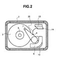
- Fig. 2 is a plan view showing the entire constitution of the information recording and reproducing device according to the embodiment of the invention.
- Fig. 3 is a mounting drawing of a state, in which an information recording and reproducing device according to the embodiment is loaded on an on-board navigation system.
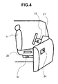
- Fig. 4 is a schematic view illustrating a manner, in which an information recording and reproducing device loaded on an automobile, is started up.
- Fig. 5 is a view illustrating a manner, in which an information recording and reproducing device loaded on an automobile, is started up.
- Disks 3 composed of magnetic films formed on surfaces of a substrate material such as aluminum or glass are rotatingly driven by a spindle motor 1 to permit information to be magnetically recorded or reproduced.
- the spindle motor 1 comprises a hub (not shown), on which the disks 3 are stacked, and a disk clamp 6 for securing the disk 3 to the hub, and rotates the hub through bearings (not shown) on a motor shaft provided on a base 2.
- the magnetic disk device comprises magnetic heads 7, which are caused to float above surfaces of the disks 3, rotatingly driven by the spindle motor, with a gap of several nm to several tens of nm therebetween, and include a magneto resistive effect element or an electromagnetic coil for magnetically writing or reading information, and a carriage 8 formed from a material such as aluminum or magnesium and serving to correctly position the magnetic heads 7 on the surfaces of the disks 3.
- the carriage 8 mounting thereon the magnetic heads 7 is driven and positioned by a voice coil motor 9 comprising a coil 10 in the form of a winding of an aluminum wire material or a copper wire material, which are covered by an insulating film, a magnet (not shown) being a permanent magnet, and a yoke (not shown) supporting the magnet to form a magnetic circuit.
- a voice coil motor 9 comprising a coil 10 in the form of a winding of an aluminum wire material or a copper wire material, which are covered by an insulating film, a magnet (not shown) being a permanent magnet, and a yoke (not shown) supporting the magnet to form a magnetic circuit.
- the carriage 8 also rotates on a carriage shaft (not shown) provided on the base 2 through bearings.
- a signal at the time of reading and writing by the magnetic heads 7 is transmitted in a reading action to a FPC (flexible printed board) 26 (Fig. 2) through the carriage 8 from magneto resistive effect elements (not shown) provided on the magnetic heads 7, and to an outside of a HDA (head disk assembly) through a read/write control IC 14 (Fig. 2), which controls a signal at the time of reading and writing by the magnetic heads 7, by a hermetical connector 13, which is positioned on an underside of the IC 14, formed from a material such as aluminum, stainless steel or iron, and bonded to the base 2.
- the hermetical connector 13 serves to intermediate electric signals inside and outside the HDA, in which hermetical connector a plurality of pins for transmission of signals and a molded portion supporting the pins are completely closed.
- the reference numeral 4 denotes an interface connector, and 16 substrate-securing screws.
- a drive current in the coil 10 on the voice coil motor 9 is transmitted to the hermetical connector 13 via the FPC 26.
- a drive current in the spindle motor 1 is transmitted to the hermetical connector 13 through a motor FPC (not shown) leading to the spindle motor 1.
- the hermetical connector 13 is connected to a main substrate 11 (Fig. 1) provided outside the HDA so that electronic parts provided on the main substrate 11 perform various control on the magnetic disk device.
- the main substrate 11 may be provided inside the HDA.
- Shafts of the spindle motor 1 and the carriage 8, and the voice coil motor 9, respectively, are fixed to the base 2 by means of screws, and a cover 15 formed from a material such as aluminum, stainless steel or iron is mounted on the base 2 with a packing (not shown) therebetween to keep closeness.
- the high volume magnetic disk device mounts therein a plurality of disks 3 to ensure storage capacity and the heads 7 are provided to face the disks 3, disk spacers 5 (Fig. 1) are provided between the disks 3. Also, spacings between the heads 7 are kept constant by finishing head mounting surfaces of the carriage 8 with good accuracy.
- FIG. 3 shows an example, in which an information recording and reproducing device 19 being a magnetic disk device as an example is mounted in an on-board navigation system 18, and Fig. 4 shows an example, in which the information recording and reproducing device 19 is mounted under a vehicle seat 17.
- bearing parts of the information recording and reproducing device 19 for example, a bearing part or parts of the spindle motor and/or the carriage are rotatingly started up. This starting of rotation can prevent minute vibrations attributable to successive collisions in the bearing part. In other words, even when vibrations are caused by the engine, minute vibrations will not be generated in the bearing part provided that the disks 3 or the like rotate.
- an example of a method of starting rotation of bearing parts of the information recording and reproducing device 19 before starting an engine in a vehicle, an example of which is an automobile, to cause vehicular vibrations comprises detecting a state, in which a key is inserted into a door key hole 24 shown in Fig. 4, and beginning feeding electric power to the information recording and reproducing device 19 on the basis of such detecting.
- Another example of such method comprises detecting a state, in which a key is inserted into a vehicle power start keyhole 23, and beginning feeding electric power to the information recording and reproducing device 19 on the basis of such detecting.
- a point of contact 25 for detecting seating is provided on a seating portion of a seat 17 as shown in Fig. 4 to detect a person seating whereby electric power begins to be fed to the information recording and reproducing device 19 under the seat. Further, according to an embodiment of the invention, binding of a seat belt 22 is detected, on the basis of which electric power begins to be fed to the information recording and reproducing device 19.
- an acceleration sensor (not shown) is mounted irrespective of whether it is mounted in the information recording and reproducing device 19 or outside the same, and output of the acceleration sensor above a predetermined level is sensed to rotate the spindle motor 1 irrespective of whether a signal processing circuit in the device is effective or non-effective.
- a point of time when a predetermined level or higher is detected by the acceleration sensor is in many cases after vibrations have been caused by the engine starting.
- it is also effective to rotate the spindle motor after the acceleration sensor detects vibrations due to departure of a vehicle after the starting of an engine.
- a period of time elapsed from the starting of an engine to departure of a vehicle is not so long and permissible in terms of micro-movement abrasion.
- a predetermined effect is obtained when the spindle motor is rotated before a vehicle begins movement.
- detecting by the acceleration sensor above a predetermined level is made by opening and closing of the door whereby the spindle motor can be rotated before the starting of an engine.
- a still further constructional example comprises a mount member (not shown) for the information recording and reproducing device 19, having the function of damping vehicular vibrations and provided with a damping member (not shown), which is formed from rubber, plastic molding or the like to be arranged between a vehicle and the information recording and reproducing device 19, in order to lessen acceleration applied to the information recording and reproducing device 19.
- a velocity sensor having been installed in a vehicle may be made use of to detect vehicular velocity to thereby rotate the spindle motor 1, and the spindle motor may continue to be rotated at all times during detecting of velocity even when the information recording and reproducing device is in non-use.
- Various detecting manners described above and shown in Fig. 5 include, in relation to a point of time when a vehicular engine is started, one, in which detecting is made before the start of an engine, and one, in which detecting is made immediately after the start of an engine.
- These detecting manners are not in fixed relationship with a point of time when an engine is started. That is, a manner, in which bonding of a seat belt is detected, is in some cases before or immediately after the start of an engine, and a manner, in which insertion of a door key is detected, is immediately after the start of an engine in the case where the engine is started from a remote location.
- a solar cell 20 provided on a dashboard 21 maybe used to store electricity in the daytime, and the stored electricity may actuate the information recording and reproducing device 19.
- the solar cell 20 may be mounted anywhere fully exposed to sunlight.
- electric power can be fed to the information recording and reproducing device 19 even before the starting of an engine to make information processing in the information recording and reproducing device. That is, in the case where an engine is started with a short interval after a door is opened and seating is effected, the use of a solar cell instead of using a battery on a vehicle is effective in ensuring a capacity of the battery in a manner, in which insertion of a door key into a door key is detected to rotate the spindle motor.
- detecting of insertion of a door key causes a battery on a vehicle to be used in rotating the spindle motor, but control may be used, in which an interval between insertion of a door key and the starting of an engine is measured to switch over to a solar cell.
- a solar cell can be used to rotate the spindle motor to thereby raise an ambient temperature to a range of usable temperature.
- a heater and a cooler (not shown) provided in the vicinity of the spindle motor 1 may be actuated by electric power outside a vehicle, a battery on a vehicle, and a solar cell prior to the starting of the spindle motor 1 to put the information recording and reproducing device 19 under the circumstance within the range of usable temperature and then start the information recording and reproducing device.
- the heater and the cooler may be mounted either inside or outside the information recording and reproducing device 19.
- electric power is fed to the spindle motor in the information recording and reproducing device in the various detecting manners shown in Fig. 5, and such feeding of electric power is essentially effected making use of a battery power source mounted on a vehicle.
- a solar cell other than such battery power source may be used as described above.
- the spindle motor may be rotatingly started when shock is detected by the acceleration sensor in a state, in which electric power from a solar cell is always fed to the information recording and reproducing device.
- the spindle motor may be rotated at all times during the traveling of a vehicle even when the information recording and reproducing device is in non-use.
- micro-movement abrasion in the bearing part is prevented by rotating the spindle motor before or immediately after vibrations due to a vehicle are caused.
- the bearing part related to rotation of the carriage as well as the spindle motor, it is effective in terms of prevention of micro-movement abrasion to make the forced turning motion of the carriage, for example, carry out the swinging motion from an unload state to a load state.
- a control means (CPU) is separately provided to control the bearing parts of the information recording and reproducing device shown in Fig. 1 on the basis of detected signals from the various detecting means as shown in Fig. 5 such that the bearing parts are rotatingly started before or immediately after vibrations due to a vehicle are caused.
- the control means described above may be incorporated into the main substrate 11 shown in Fig. 1.
- the bearing parts used in rotation and/or rotational drive of the spindle motor and/or the carriage can be prevented from subjecting to micro-movement abrasion to be rapidly degraded in rotating and/or turning accuracy.
Landscapes
- Rotational Drive Of Disk (AREA)
- Moving Of Head For Track Selection And Changing (AREA)
- Rolling Contact Bearings (AREA)
Abstract
Description
Claims (9)
- A control device for an on-board information recording and reproducing device (19), which includes a disk (3), a head (7) for recording/reproducing information on/from the disk (3), a carriage (8) for positioning the head (7) on a surface of the disk (3), a carriage bearing, a spindle motor (1) for rotating the disk (3), and a spindle bearing, the control device comprising:means for detecting an activity on the vehicle which takes place before vehicular vibrations are caused; andcontrol means for starting rotation and/or oscillation of at least one of said bearings on the basis of a signal from the detecting means.
- The device of claim 1, comprising an acceleration sensor provided on the vehicle or the information recording and reproducing device (19), wherein said detecting means is adapted to detect whether the signal from the acceleration sensor has exceeded a predetermined value.
- The device of claim 1, comprising a velocity sensor provided in the vehicle, wherein said detecting means is adapted to detect the output from the velocity sensor.
- The control device of any preceding claim, wherein said activity is one of the following actions:insertion of a door key (24),insertion of the starting key (23),a seat (25) being taken,fastening of a seat belt (22).
- The control device of any preceding claim, further comprising a solar cell (20) mounted on the vehicle to serve as a power source for starting rotation/oscillation of said bearings.
- The control device of claim 2, wherein the acceleration sensor is mounted on a door adjacent the driver's seat.
- A control method for an on-board information recording and reproducing device (19), which includes a disk (3), a head (7) for recording/reproducing information on/from the disk (3), a carriage (8) for positioning the head (7) on a surface of the disk (3), a carriage bearing, a spindle motor (1) for rotating the disk (3), and a spindle bearing, the method comprising the steps of:detecting an activity on the vehicle which takes place before the vehicle continuously causes vibrations; andstarting rotation and/or oscillation of at least on of said bearings on the basis of the detected activity.
- The method of claim 7, wherein said detection is made by an acceleration sensor provided on the vehicle or the information recording and reproducing device (19) and detecting whether acceleration has exceeded a predetermined value.
- The method of claim 7, wherein said detection is made by means of a velocity meter mounted on a vehicle for detecting the vehicular velocity.
Applications Claiming Priority (2)
| Application Number | Priority Date | Filing Date | Title |
|---|---|---|---|
| JP2002115104 | 2002-04-17 | ||
| JP2002115104A JP2003317366A (en) | 2002-04-17 | 2002-04-17 | Control device and control method for information recording / reproducing device |
Publications (3)
| Publication Number | Publication Date |
|---|---|
| EP1355305A2 true EP1355305A2 (en) | 2003-10-22 |
| EP1355305A3 EP1355305A3 (en) | 2004-10-27 |
| EP1355305B1 EP1355305B1 (en) | 2008-01-23 |
Family
ID=28672648
Family Applications (1)
| Application Number | Title | Priority Date | Filing Date |
|---|---|---|---|
| EP02021287A Expired - Lifetime EP1355305B1 (en) | 2002-04-17 | 2002-09-19 | Controller and control method for information recording and reproducing device |
Country Status (6)
| Country | Link |
|---|---|
| US (1) | US6965487B2 (en) |
| EP (1) | EP1355305B1 (en) |
| JP (1) | JP2003317366A (en) |
| KR (1) | KR100494609B1 (en) |
| CN (1) | CN1452165A (en) |
| DE (1) | DE60224779D1 (en) |
Families Citing this family (5)
| Publication number | Priority date | Publication date | Assignee | Title |
|---|---|---|---|---|
| US7042663B2 (en) * | 2002-10-03 | 2006-05-09 | Hitachi Global Storage Technologies Netherlands B.V. | Magnetic disk protection mechanism, computer system comprising protection mechanism, protection method for magnetic disk, and program for protection method |
| US7913108B1 (en) * | 2006-03-28 | 2011-03-22 | Emc Corporation | System and method for improving disk drive performance during high frequency vibration conditions |
| US7872827B2 (en) * | 2007-07-27 | 2011-01-18 | Seagate Technology Llc | Impact protection for a retractable control object |
| JP2009259300A (en) * | 2008-04-11 | 2009-11-05 | Hitachi Ltd | Optical disk drive apparatus and its control method |
| JP2010225207A (en) * | 2009-03-19 | 2010-10-07 | Alphana Technology Co Ltd | Disk drive device |
Family Cites Families (21)
| Publication number | Priority date | Publication date | Assignee | Title |
|---|---|---|---|---|
| JPS60222340A (en) * | 1984-04-20 | 1985-11-06 | Matsushita Electric Ind Co Ltd | tape cassette storage device |
| US4812838A (en) * | 1984-08-03 | 1989-03-14 | Nippondenso Co., Ltd. | Vehicle seat drive control device |
| US4688244A (en) * | 1986-11-10 | 1987-08-18 | Marwan Hannon | Integrated cargo security system |
| JPS63201949A (en) * | 1987-02-18 | 1988-08-22 | Canon Inc | Protection device for in-vehicle recording or playback equipment |
| DE3828858A1 (en) * | 1987-09-29 | 1989-04-06 | Pioneer Electronic Corp | NAVIGATION DEVICE FOR A MOTOR VEHICLE |
| JPH03135853A (en) * | 1989-10-20 | 1991-06-10 | Hitachi Ltd | Automobile control device and automobile control method |
| JPH0574038A (en) * | 1991-09-18 | 1993-03-26 | Oki Electric Ind Co Ltd | On-vehicle trerminal control system |
| JPH05205388A (en) * | 1992-01-27 | 1993-08-13 | Matsushita Electric Ind Co Ltd | Vibration resistant compact disc player |
| KR0138861B1 (en) | 1994-12-14 | 1998-06-15 | 양승택 | Jpeg standard quantizer inverse quantizer architecture |
| FR2743168B1 (en) * | 1996-01-02 | 1998-03-06 | Integral Media Sa | "MULTIMEDIA" COMPUTER EQUIPMENT FOR THE AUTOMATIC BROADCASTING OF "MULTIMEDIA" ANIMATIONS BASED ON A GEOGRAPHICAL POSITION, A TIME AND / OR A DATE ON BOARD A VEHICLE |
| JP4015744B2 (en) * | 1997-07-24 | 2007-11-28 | 本田技研工業株式会社 | Vehicle diagnostic device |
| JPH11353783A (en) * | 1998-06-02 | 1999-12-24 | Pioneer Electron Corp | Disk recording and reproducing device |
| JP2001057010A (en) | 1999-08-17 | 2001-02-27 | Toshiba Corp | Magnetic recording / reproducing apparatus and operation guarantee method in the apparatus |
| US6204772B1 (en) * | 1999-12-16 | 2001-03-20 | Caterpillar Inc. | Method and apparatus for monitoring the position of a machine |
| JP3966534B2 (en) * | 2000-04-24 | 2007-08-29 | パイオニア株式会社 | Recording / playback device |
| EP1152424A3 (en) | 2000-04-24 | 2003-07-30 | Pioneer Corporation | Disk drive device |
| JP3835790B2 (en) * | 2000-04-24 | 2006-10-18 | パイオニア株式会社 | Drive control system for in-vehicle hard disk drive |
| JP2001332049A (en) | 2000-05-16 | 2001-11-30 | Hitachi Ltd | Magnetic disk drive |
| JP2002025171A (en) * | 2000-07-13 | 2002-01-25 | Hitachi Ltd | In-vehicle magnetic disk unit |
| US6633448B1 (en) * | 2000-09-06 | 2003-10-14 | International Business Machines Corporation | Disk data storage device having improved tolerance for stressful environments |
| US6546456B1 (en) * | 2000-09-08 | 2003-04-08 | International Business Machines Corporation | Method and apparatus for operating vehicle mounted disk drive storage device |
-
2002
- 2002-04-17 JP JP2002115104A patent/JP2003317366A/en active Pending
- 2002-09-18 US US10/245,385 patent/US6965487B2/en not_active Expired - Fee Related
- 2002-09-19 EP EP02021287A patent/EP1355305B1/en not_active Expired - Lifetime
- 2002-09-19 DE DE60224779T patent/DE60224779D1/en not_active Expired - Lifetime
- 2002-09-25 KR KR10-2002-0057973A patent/KR100494609B1/en not_active Expired - Fee Related
- 2002-09-26 CN CN02143933A patent/CN1452165A/en active Pending
Also Published As
| Publication number | Publication date |
|---|---|
| EP1355305B1 (en) | 2008-01-23 |
| EP1355305A3 (en) | 2004-10-27 |
| KR100494609B1 (en) | 2005-06-13 |
| KR20030082882A (en) | 2003-10-23 |
| DE60224779D1 (en) | 2008-03-13 |
| US6965487B2 (en) | 2005-11-15 |
| CN1452165A (en) | 2003-10-29 |
| JP2003317366A (en) | 2003-11-07 |
| US20030197967A1 (en) | 2003-10-23 |
Similar Documents
| Publication | Publication Date | Title |
|---|---|---|
| US7020548B2 (en) | Vehicle drive recorder | |
| US6144178A (en) | Disk drive with controlled reduced internal pressure | |
| JP2003228972A (en) | On-vehicle disk drive unit | |
| US6965487B2 (en) | Controller for information recording and reproducing device and control method for the information recording and reproducing device | |
| US5523912A (en) | Magnetic head positioner for magnetic disk apparatus which can prevent mechanical shock | |
| US20050180055A1 (en) | Actuator latch apparatus for disk drive | |
| JP2004039061A (en) | In-vehicle information processing device, magnetic disk device, and control method for in-vehicle information processing device | |
| WO1994009489A1 (en) | Passive non-contact magnetic latch | |
| US6967813B2 (en) | Method of mounting magnetic disk device, cabinet for magnetic disk device, and magnetic disk device | |
| US6134086A (en) | Actuator crash stopper for a hard disk drive | |
| US20080285176A1 (en) | Storage device | |
| US20070070539A1 (en) | Method and apparatus for controlling motor rotation in hard disk drive | |
| US7423845B2 (en) | Recording disk drive with enhanced swinging member | |
| US20020141116A1 (en) | Actuator latch for hard disk drive | |
| US8467152B2 (en) | Actuator latching mechanism for magnetic disk drive | |
| US7379272B2 (en) | Disk drive internal latch assembly with movement restriction member to generate opposing rotation moments on shaft opposing sides | |
| US20070103809A1 (en) | Retracting method of hard disk drive, hard disk drive adopting the method, and recording medium storing program for executing the method | |
| KR100723502B1 (en) | Base member and hard disk drive having same | |
| KR19990070502A (en) | Actuator on-track control device and method in hard disk drive | |
| JP4234634B2 (en) | Magnetic disk unit | |
| JP2007157319A (en) | Actuator and hard disk drive having the same | |
| CN1992066A (en) | Fixing device of vehicle-carrying computer hand disk system | |
| JPH06282930A (en) | Control method for magnetic disk device | |
| JP2003077212A (en) | On-vehicle disk driver, car navigation equipment, disk driving method, and navigation method | |
| JPS60222340A (en) | tape cassette storage device |
Legal Events
| Date | Code | Title | Description |
|---|---|---|---|
| PUAI | Public reference made under article 153(3) epc to a published international application that has entered the european phase |
Free format text: ORIGINAL CODE: 0009012 |
|
| AK | Designated contracting states |
Kind code of ref document: A2 Designated state(s): AT BE BG CH CY CZ DE DK EE ES FI FR GB GR IE IT LI LU MC NL PT SE SK TR |
|
| AX | Request for extension of the european patent |
Extension state: AL LT LV MK RO SI |
|
| PUAL | Search report despatched |
Free format text: ORIGINAL CODE: 0009013 |
|
| AK | Designated contracting states |
Kind code of ref document: A3 Designated state(s): AT BE BG CH CY CZ DE DK EE ES FI FR GB GR IE IT LI LU MC NL PT SE SK TR |
|
| AX | Request for extension of the european patent |
Extension state: AL LT LV MK RO SI |
|
| RIC1 | Information provided on ipc code assigned before grant |
Ipc: 7G 11B 21/12 B Ipc: 7G 11B 19/08 B Ipc: 7G 11B 21/02 B Ipc: 7G 11B 19/04 A Ipc: 7G 11B 31/00 B Ipc: 7G 11B 19/28 B |
|
| RAP1 | Party data changed (applicant data changed or rights of an application transferred) |
Owner name: HITACHI GLOBAL STORAGE TECHNOLOGIES JAPAN, LTD. |
|
| 17P | Request for examination filed |
Effective date: 20050420 |
|
| AKX | Designation fees paid |
Designated state(s): DE FR GB |
|
| 17Q | First examination report despatched |
Effective date: 20060707 |
|
| GRAP | Despatch of communication of intention to grant a patent |
Free format text: ORIGINAL CODE: EPIDOSNIGR1 |
|
| GRAS | Grant fee paid |
Free format text: ORIGINAL CODE: EPIDOSNIGR3 |
|
| GRAA | (expected) grant |
Free format text: ORIGINAL CODE: 0009210 |
|
| AK | Designated contracting states |
Kind code of ref document: B1 Designated state(s): DE FR GB |
|
| REG | Reference to a national code |
Ref country code: GB Ref legal event code: FG4D |
|
| REF | Corresponds to: |
Ref document number: 60224779 Country of ref document: DE Date of ref document: 20080313 Kind code of ref document: P |
|
| EN | Fr: translation not filed | ||
| PLBE | No opposition filed within time limit |
Free format text: ORIGINAL CODE: 0009261 |
|
| STAA | Information on the status of an ep patent application or granted ep patent |
Free format text: STATUS: NO OPPOSITION FILED WITHIN TIME LIMIT |
|
| 26N | No opposition filed |
Effective date: 20081024 |
|
| PG25 | Lapsed in a contracting state [announced via postgrant information from national office to epo] |
Ref country code: DE Free format text: LAPSE BECAUSE OF FAILURE TO SUBMIT A TRANSLATION OF THE DESCRIPTION OR TO PAY THE FEE WITHIN THE PRESCRIBED TIME-LIMIT Effective date: 20080424 |
|
| PG25 | Lapsed in a contracting state [announced via postgrant information from national office to epo] |
Ref country code: FR Free format text: LAPSE BECAUSE OF FAILURE TO SUBMIT A TRANSLATION OF THE DESCRIPTION OR TO PAY THE FEE WITHIN THE PRESCRIBED TIME-LIMIT Effective date: 20081114 |
|
| GBPC | Gb: european patent ceased through non-payment of renewal fee |
Effective date: 20080919 |
|
| PG25 | Lapsed in a contracting state [announced via postgrant information from national office to epo] |
Ref country code: GB Free format text: LAPSE BECAUSE OF NON-PAYMENT OF DUE FEES Effective date: 20080919 |