EP1354832A2 - Sheet conveying device and image forming apparatus including the sheet conveying device - Google Patents
Sheet conveying device and image forming apparatus including the sheet conveying device Download PDFInfo
- Publication number
- EP1354832A2 EP1354832A2 EP03008761A EP03008761A EP1354832A2 EP 1354832 A2 EP1354832 A2 EP 1354832A2 EP 03008761 A EP03008761 A EP 03008761A EP 03008761 A EP03008761 A EP 03008761A EP 1354832 A2 EP1354832 A2 EP 1354832A2
- Authority
- EP
- European Patent Office
- Prior art keywords
- sheet conveying
- conveying device
- biasing member
- driven roller
- drive roller
- Prior art date
- Legal status (The legal status is an assumption and is not a legal conclusion. Google has not performed a legal analysis and makes no representation as to the accuracy of the status listed.)
- Granted
Links
Images



Classifications
-
- B—PERFORMING OPERATIONS; TRANSPORTING
- B65—CONVEYING; PACKING; STORING; HANDLING THIN OR FILAMENTARY MATERIAL
- B65H—HANDLING THIN OR FILAMENTARY MATERIAL, e.g. SHEETS, WEBS, CABLES
- B65H5/00—Feeding articles separated from piles; Feeding articles to machines
- B65H5/06—Feeding articles separated from piles; Feeding articles to machines by rollers or balls, e.g. between rollers
- B65H5/062—Feeding articles separated from piles; Feeding articles to machines by rollers or balls, e.g. between rollers between rollers or balls
-
- B—PERFORMING OPERATIONS; TRANSPORTING
- B65—CONVEYING; PACKING; STORING; HANDLING THIN OR FILAMENTARY MATERIAL
- B65H—HANDLING THIN OR FILAMENTARY MATERIAL, e.g. SHEETS, WEBS, CABLES
- B65H2301/00—Handling processes for sheets or webs
- B65H2301/30—Orientation, displacement, position of the handled material
- B65H2301/33—Modifying, selecting, changing orientation
- B65H2301/331—Skewing, correcting skew, i.e. changing slightly orientation of material
-
- B—PERFORMING OPERATIONS; TRANSPORTING
- B65—CONVEYING; PACKING; STORING; HANDLING THIN OR FILAMENTARY MATERIAL
- B65H—HANDLING THIN OR FILAMENTARY MATERIAL, e.g. SHEETS, WEBS, CABLES
- B65H2402/00—Constructional details of the handling apparatus
- B65H2402/30—Supports; Subassemblies; Mountings thereof
- B65H2402/31—Pivoting support means
Definitions
- the present invention relates to a sheet conveying device for use in an image forming apparatus such as a copying machine, a printer, a facsimile machine, a multi-functional image forming apparatus, or other similar image forming apparatuses.
- a background sheet conveying device which conveys a sheet in a predetermined direction while pinching the sheet between a drive roller and a driven roller which is press-contacted against the drive roller, has been proposed.
- a roller support mechanism that press-contacts the driven roller against the drive roller in the above-described background sheet conveying device
- Japanese Laid-open patent publication No. 63-66583 describes a roller support mechanism that uses a plate spring functioning as a roller support member. The plate spring rotatably supports a driven roller and exerts a bias force on the driven roller to be press-contacted against a drive roller.
- Japanese Laid-open patent publication No. 9-188449 also describes a roller support mechanism that uses a plate spring to bias a driven roller against a drive roller.
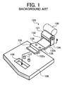
- FIG. 1 is a perspective view of a background sheet conveying device including a roller support mechanism using a plate spring.
- a pair of sheet conveying rollers 123 include a drive roller 130 (illustrated by dotted lines) and a driven roller 131.
- a plate spring 132 rotatably supports the driven roller 131.
- the driven roller 131 is supported by a pair of support arms 134 which are provided on one end part 132b of the plate spring 132.
- Two through holes 138 are formed in the middle part of the plate spring 132 at a predetermined distance apart.
- the background sheet conveying device of FIG. 1 further includes a guide plate 109.
- the guide plate 109 includes a support hole 136 and two protrusions 137 on the surface of the guide plate 109 at a predetermined distance apart.
- the plate spring 132 is fixed to the guide plate 109 by inserting the other end part 132a and a stepped bent part 133 of the plate spring 132 into the support hole 136 and by engaging the two protrusions 137 that are provided on the guide plate 109 in the two through holes 138 in the plate spring 132.
- FIG. 2 is a perspective view of another background sheet conveying device including a roller support mechanism using a plate spring.
- a plate spring 102 rotatably supports a driven roller 101 on one end part 102a of the plate spring 102 and biases the driven roller 101 against a drive roller 103.
- the plate spring 102 is fixed to a plate-shaped holding member (not shown) that holds the plate spring 102 by press-fitting a protrusion 104a that is provided on the holding member into a hole (not shown) that is formed at the other end part 102b of the plate spring 102.
- FIG. 3 is a perspective view of the background sheet conveying device of FIG. 2 according to an alternative example.
- the plate spring 102 is fixed to a plate-shaped holding member (not shown) that holds the plate spring 102 by securing the other end part 102b of the plate spring 102 to the holding member by a screw 105.
- the position of the driven roller 131 relative to the drive roller 130 is regulated by the two protrusions 137.
- the distance between the two protrusions 137 is relatively small, it may be difficult to insure the accuracy of the position of the driven roller 131 relative to the drive roller 130.
- the plate spring 102 is fixed to the plate-shaped holding member by press-fitting the protrusion 104a on the holding member into the hole of the plate spring 102 by use of a jig (not shown), and by securing the other end part 102b of the plate spring 102 to the holding member by the screw 105.
- a jig not shown
- the plate spring 102 may be bent around the screw 105 due to torque.
- an object of the present invention is to provide a sheet conveying device in which the accuracy of the position of a driven roller relative to a drive roller, specifically, parallelism of the driven roller and the drive roller, is increased and which prevents a sheet from being skewed, and to provide an image forming apparatus including the sheet conveying device.
- a sheet conveying device comprises a rotatably supported drive roller, a rotatably supported driven roller, a biasing member configured to rotatably support one of the drive roller and the driven roller and to bias one of the drive roller and the driven roller against the other one of the drive roller and the driven roller; and a holding member configured to pivotally hold the biasing member.
- a pivoting axis of the pivot means allowing the pivoting of the biasing member is at least essentially parallel to a straight line extending at least essentially vertical through the rotational axes of the drive roller and the driven roller and wherein the pivoting axis is positioned in a plane extending at least essentially vertically through the rotational axes of the drive roller and the driven roller in at least essentially the center of their respective axial extension.
- pivoting axis of a pivot means allowing the pivoting of the biasing member is positioned in a distance to the at least essentially common plane of the axes of rotation of the drive roller and the driven roller.
- the pivoting axis of the pivot means is situated upstream of a nip between the drive roller and the driven roller with respect to the sheet conveying direction.
- a sheet conveying device includes a drive roller with a rotational axis, a driven roller with a rotational axis, a biasing member configured to rotatably support one of the drive roller and the driven roller and to bias one of the drive roller and the driven roller against the other one of the drive roller and the driven roller, and a holding member configured to pivotally hold the biasing member.
- the sheet conveying device conveys a sheet while rotating the drive roller and the driven roller and passing the sheet through a nip part formed between the drive roller and the driven roller.
- an image forming apparatus includes an image carrier configured to carry an image, and the above-described sheet conveying device configured to convey a sheet that receives the image on at least one side of the sheet.
- FIG. 4 is a schematic view of a cross section of a main part of an image forming apparatus including a sheet conveying device according to an embodiment of the present invention.
- a reference character (S) designates a sheet that is pressed against a sheet feeding roller 2 by a sheet raising mechanism (not shown).
- a sheet separation pad 3 is provided opposite to the sheet feeding roller 2 and is biased against the sheet feeding roller 2 by a compression spring 3a.
- the sheet feeding roller 2 is driven to rotate in accordance with a sheet feeding signal, thereby separating a top sheet from the stack of sheets (S) and feeding the top sheet toward a pair of registration rollers 6.
- the sheet feeding roller 2 continues to rotate for a predetermined period of time after the sheet (S) reaches the registration rollers 6, and then stops rotating. By this rotation of the sheet feeding roller 2, the sheet (S) becomes bent between the registration rollers 6 and the sheet feeding roller 2. Subsequently, the registration rollers 6 start rotating, thereby conveying the sheet (S).
- the sheet (S) is guided by a guide plate 9 toward a nip part formed between a photoreceptor 7 and a transfer roller 8. A toner image that has been formed on the photoreceptor 7 is transferred onto the sheet (S) at the nip part between the photoreceptor 7 and the transfer roller 8.
- the photoreceptor 7 functions as an image carrier that carries a toner image on the surface thereof.
- the toner image is fixed onto the sheet (S) while the sheet (S) passes through a nip part formed between a fixing roller 10a and a pressure roller 10b.
- the sheet (S) having a fixed toner image thereon is directed toward a pair of sheet discharging rollers 11 by a pivotable separation pick 13 that is located in the position illustrated by full outlines in FIG. 4.
- the sheet discharging rollers 11 are configured to be rotated in both forward and reverse directions.
- the sheet (S) is discharged from the image forming apparatus by the sheet discharging rollers 11 that rotates in the forward direction.
- the separation pick 13 moves to the position illustrated by dotted lines in FIG. 4, and the sheet discharging rollers 11 start to rotate in the reverse direction.
- the sheet (S) is conveyed to a sheet conveying device including a drive roller 30 and a driven roller 31 that is press-contacted against the drive roller 30.
- the sheet conveying device conveys the sheet (S) toward the registration rollers 6 while passing the sheet (S) through the nip part formed between the drive roller 30 and the driven roller 31 and while guiding the sheet (S) by the guide plate 9. Subsequently, the registration rollers 6 feed the sheet (S) to the nip part between the photoreceptor 7 and the transfer roller 8 again. The toner image that has been formed on the photoreceptor 7 is transferred onto the rear side of the sheet (S) at the nip part between the photoreceptor 7 and the transfer roller 8.
- FIG. 5 is a perspective view of a sheet conveying device in the image forming apparatus of FIG. 4 according to an embodiment of the present invention.
- the sheet conveying device of FIG. 5 includes a pair of sheet conveying rollers 23 having the drive roller 30 and the driven roller 31 that is press-contacted against the driven roller 31, a plate spring 32, for example, formed from a spring steel serving as a biasing member that rotatably supports the driven roller 31 and biases the driven roller 31 against the drive roller 30, and the guide plate 9 serving as a holding member that pivotally holds the plate spring 32.
- the driven roller 31 is rotatably supported by a pair of support arms 34 which are provided on one end part 32b of the plate spring 32. Specifically, the shaft (not shown) of the driven roller 31 is rotatably supported by the pair of support arms 34 while passing the shaft of the driven roller 31 through holes (not shown) which are formed in the support arms 34.
- the plate spring 32 includes a through hole 38 that is formed at a center part of the plate spring 32 in the longitudinal direction of the plate spring 32. Further, the other end part 32a of the plate spring 32 is folded in L shape in cross section. A reference numeral 33 indicates a stepped folded portion of the plate spring 32.
- a support hole 36 is formed in the guide plate 9 at an appropriate position, and a protrusion 37 is provided on the guide plate 9 in the vicinity of the support hole 36.
- the protrusion 37 is molded integral with the guide plate 9. Alternatively, the protrusion 37 as a separate member may be attached onto the surface of the guide plate 9.
- the other end part 32a and the stepped folded portion 33 of the plate spring 32 are inserted into the support hole 36 in the guide plate 9. Further, the protrusion 37 on the guide plate 9 is press-fitted into the through hole 38 in the plate spring 32. By attaching the plate spring 32 to the guide plate 9 as above, the plate spring 32 is held by the guide plate 9.
- FIG. 6 is a perspective view of a sheet conveying device according to another embodiment of the present invention.
- the construction of the sheet conveying device of FIG. 6 is similar to that of the sheet conveying device of FIG. 5 with the exception of a screw hole 39 and a stepped screw 40.
- the screw hole 39 is formed in the guide plate 9 in the vicinity of the support hole 36.
- the stepped screw 40 that is subjected to a header process is inserted into the through hole 38 and is threaded into the screw hole 39.
- the height of a step portion 40a of the stepped screw 40 is set to be greater than the thickness of the plate spring 32 to prevent the plate spring 32 from being in intimate contact with the surface of the guide plate 9. That is, the plate spring 32 is spaced from the guide plate 9 via the step portion 40a.
- the plate spring 32 is configured to be pivotable around the step portion 40a of the stepped screw 40 (i.e., around an axis line of the stepped screw 40).
- the protrusion 37 on the guide plate 9 may expand due to the heat that is radiated from the heating member. As a result, little clearance may be left between the protrusion 37 and the through hole 38, and the shape of the protrusion 37 may be changed due to the heat, thereby causing the plate spring 32 not to pivot around the protrusion 37 smoothly.
- the plate spring 32 can stably pivot around the step portion 40a of the stepped screw 40.
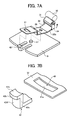
- FIG. 7A is a perspective view of a sheet conveying device according to another embodiment of the present invention.
- FIG. 7B is an enlarged perspective view of main parts of the sheet conveying device of FIG. 7A.
- FIG. 8 is an exploded top view of main parts of the sheet conveying device of FIG. 7A.
- the construction of the sheet conveying device of FIG. 7A is similar to that of the sheet conveying device of FIG. 5.
- the plate spring 32 further includes a hole 41 on the opposite side from the driven roller 31 to catch a support pawl 42 that is provided on the guide plate 9.
- the support pawl 42 when attaching the plate spring 32 to the guide plate 9, in addition to the fitting of the protrusion 37 on the guide plate 9 into the through hole 38, the support pawl 42 is inserted into the hole 41 and is caught by an edge portion 41a of the hole 41, thereby pressing the plate spring 32 toward the guide plate 9 by the support pawl 42.
- the hole 41 has an opening greater than the support pawl 42 so as not only to pass the support pawl 42 through the hole 41 but also to allow the plate spring 32 to move.
- the edge portion 41a of the hole 41 that is located on the side opposite to the driven roller 31 is in the shape of an arc concentric with the through hole 38.
- the edge portion 41a of the hole 41 is curved outward in a direction away from the through hole 38.
- the support pawl 42 includes a tip end portion 42a and a base portion 42c.
- the tip end portion 42a includes a circumferential surface portion 42b
- the base portion 42c includes a side surface portion 42d.
- Each of the circumferential surface portion 42b and the side surface portion 42d is in the shape of an arc.
- the side surface portion 42d is in the shape of an arc concentric with the edge portion 41a of the hole 41.
- the distance between the center of the protrusion 37 on the guide plate 9 and the circumferential surface portion 42b of the tip end portion 42a of the support pawl 42 is set to be greater than the distance between the center of the through hole 38 in the plate spring 32 and the edge portion 41a of the hole 41.
- the distance between the center of the protrusion 37 on the guide plate 9 and the side surface portion 42d of the base portion 42c of the support pawl 42 is set to be less than the distance between the center of the through hole 38 in the plate spring 32 and the edge portion 41a of the hole 41.
- the center lines of the through hole 38 and hole 41 in the plate spring 32 do not have to be aligned with the center lines of the protrusion 37 and support pawl 42 on the guide plate 9, respectively.
- the amount of the support pawl 42 that climbs over the edge portion 41a of the hole 41 and that is caught by the edge portion 41a becomes substantially equal regardless of whether there is a deviation in the above-described angle, because respective shapes of corresponding parts of the plate spring 32 to those of the guide plate 9 are a circle, a cylinder, and arcs.
- the side surface portion 42d of the base portion 42c of the support pawl 42 is in the shape of an arc concentric with the edge portion 41a of the hole 41. Further, as described above, the edge portion 41a of the hole 41 is in non-contact relation to the side surface portion 42d of the base portion 42c.
- the construction of the sheet conveying device, and each shape of the side surface portion 42d and the edge portion 41a is not limited to the above and may be changed so long as similar effects can be obtained.
- the edge portion 41a of the hole 41 may be in point-contact or substantially point-contact with the side surface portion 42d of the base portion 42c.
- the gap (t) between the edge portion 41a of the hole 41 and the side surface portion 42d of the base portion 42c of the support pawl 42 may not have to be kept constant so long as the edge portion 41a of the hole 41 can be maintained in point-contact or substantially point-contact with the side surface portion 42d of the base portion 42c.
- a shaft axis 30a of the drive roller 30 needs to be in parallel with a shaft axis 31a of the driven roller 31. Further, the drive roller 30 and the driven roller 31 need to be positioned so that the shaft axes 30a and 31a are perpendicular to the sheet conveying direction.
- the plate spring 32 is attached to the guide plate 9 and is slanted, for example, leftward with respect to the shaft axis 30a of the drive roller 30 as illustrated in FIG.
- the driven roller 31 that is supported by the plate spring 32 is press-contacted against the drive roller 30 in the condition that the shaft axis 31a of the driven roller 31 is slanted leftward with respect to the shaft axis 30a of the drive roller 30 as illustrated in FIG. 9.
- the guide plate 9 serving as a holding member is configured to pivotally hold the plate spring 32.
- the plate spring 32 pivots around the protrusion 37 or the axis line of the stepped screw 40 by the turning moment produced in the plate spring 32 by the drive force generated by the drive roller 30, and thereby the shaft axis 31a of the driven roller 31 can be kept in parallel with the shaft axis 30a of the drive roller 30 while the drive roller 30 is rotating.
- the position of the shaft of the driven roller 31 can be properly aligned with the position of the shaft of the drive roller 30 by the turning moment produced in the plate spring 32 by the drive force generated by the drive roller 30 in a simple construction of the sheet conveying device.
- the shaft axis 31a of the driven roller 31 can be kept in parallel with the shaft axis 30a of the drive roller 30 while the drive roller 30 is rotating.
- the sheet (S) can be conveyed smoothly in a sheet conveying path in the image forming apparatus without occurrence of sheet skew, and thereby a good quality image can be obtained in the image forming apparatus.
- the plate spring 32 is used as a biasing member that rotatably supports the driven roller 31 and biases the driven roller 31 against the drive roller 30.
- the biasing member is not limited to the plate spring 32 and may be other members having a resilient property to cause the driven roller 31 to be press-contacted against the drive roller 30.
- the plate spring 32 may rotatably support the drive roller 30 in place of the driven roller 31 to bias the drive roller 30 against the driven roller 31. In this case, the position of the shaft of the drive roller 30 may be properly aligned with the position of the shaft of the driven roller 31.
- the present invention is applied to a sheet conveying device including a pair of sheet conveying rollers in an image forming apparatus that forms images on dual sides of a sheet.
- the present invention is not limited to the embodiments.
- the present invention may be applied to a sheet conveying device for use in an image forming apparatus that forms an image on a single side of a sheet.
- the present invention may be applied to any devices including a drive roller and a driven roller that is press-contacted against the drive roller in an image forming apparatus.
- a pair of drive and driven rollers may include a fixing roller and a pressure roller in a heat fixing device that fixes a toner image onto the surface of a sheet, may include sheet discharging rollers in a sheet discharging device that discharges a sheet from an image forming apparatus, or may include sheet feeding rollers in a sheet feeding device that feeds sheets which are stacked in a sheet feeding cassette toward an image forming section.
- the present invention may be applied to a conveyance device for use in an apparatus other than an image forming apparatus, which conveys a sheet or film shaped member.
Landscapes
- Engineering & Computer Science (AREA)
- Mechanical Engineering (AREA)
- Delivering By Means Of Belts And Rollers (AREA)
Abstract
Description
a rotatably supported drive roller,
a rotatably supported driven roller,
a biasing member configured to rotatably support one of the drive roller and the driven roller and to bias one of the drive roller and the driven roller against the other one of the drive roller and the driven roller; and
a holding member configured to pivotally hold the biasing member.
Claims (14)
- A sheet conveying device comprising:a rotatably supported drive roller (30);a rotatably supported driven roller (31);a biasing member (32) configured to rotatably support one of the drive roller (30) and the driven roller (31) and to bias one of the drive roller (30) and the driven roller (31) against the other one of the drive roller (30) and the driven roller (31); anda holding member (9) configured to pivotally hold the biasing member (32).
- The sheet conveying device according to claim 1, wherein a pivoting axis of the pivot means (37, 38; 38, 39, 40) allowing the pivoting of the biasing member (32) is at least essentially parallel to a straight line extending at least essentially vertical through the rotational axes of the drive roller (30) and the driven roller (31) and wherein the pivoting axis is positioned in a plane extending at least essentially vertical through the rotational axes of the drive roller (30) and the driven roller (31) in at least essentially the center of their respective axial extension.
- The sheet conveying device according to claim 2
wherein the pivoting axis of a pivot means (37, 38; 38, 39, 40) allowing the pivoting of the biasing member (32) is positioned in a distance to an at least essentially common plane of axes of rotation of the drive roller (30) and the driven roller (31). - The sheet conveying device according to claim 3,
wherein the pivoting axis of the pivot means is situated upstream of a nip between the drive roller (30) and the driven roller (31) with respect to the sheet conveying direction. - A sheet conveying device, comprising:wherein the sheet conveying device conveys a sheet (S) while rotating the drive roller (30) and the driven roller (31) and passing a sheet (S) through the nip part formed between the drive roller (30) and the driven roller (31).a drive roller (30) with a rotational axis;a driven roller (31) with a rotational axis;a biasing member (32) configured to rotatably support one of the drive roller (30) and the driven roller (31) and to bias one of the drive roller (30) and the driven roller (31) against the other one of the drive roller (30) and the driven roller (31); anda holding member (9) configured to pivotally hold the biasing member (32),
- The sheet conveying device according to any of claims 1 to 5, wherein a position of the rotational axis of the drive roller (30) and a position of the rotational axis of the driven roller (31) are aligned to be substantially parallel with each other by a turning moment that is produced in the biasing member (32) by a drive force generated by the drive roller (30).
- The sheet conveying device according to one of claims 1 to 6, wherein the biasing member (32) includes a first hole (38), and the holding member (9) includes a protrusion (37) on a surface of the holding member (9), and wherein the biasing member (32) is pivotally held by the holding member (9) by fitting the protrusion (37) into the first hole (38) in the biasing member (32) so that the biasing member (32) pivots around the protrusion (37).
- The sheet conveying device according to one of claims 1 to 6, wherein the biasing member (32) includes a first hole (38), and the holding member (9) includes a screw hole (39), and wherein the biasing member (32) is pivotally held by the holding member (9) by inserting a stepped screw (40) into the first hole (38) and by threading the stepped screw (40) into the screw hole (39) so that the biasing member (32) pivots around an axis line of the stepped screw (40).
- The sheet conveying device according to claim 8, wherein the stepped screw (40) includes a step portion (40a) that has a greater height than a thickness of the biasing member (32), and the biasing member (32) is spaced from the holding member (9) via the step portion (40a) of the stepped screw (40).
- The sheet conveying device according to claim 7, wherein the biasing member (32) rotatably supports one of the drive roller (30) and the driven roller (31) at one end part of the biasing member (32), and wherein the biasing member (32) further includes a second hole (41) including an edge portion (41a) at the other end part of the biasing member (32) and on the opposite side from one of the drive roller (30) and the driven roller (31), and wherein the holding member (9) further includes a pawl portion (42), and wherein the biasing member (32) is pivotally held by the holding member (9) by fitting the protrusion (37) into the first hole (38) in the biasing member (32) and by causing the pawl portion (42) to be caught by the edge portion (41a) of the second hole (41).
- The sheet conveying device according to claim 10, wherein the edge portion (41a) of the second hole (41) has an arc shape and is curved outward in a direction away from the first hole (38), and wherein a part (42d) of the pawl portion (42), which faces the edge portion (41a) of the second hole (41) when the pawl portion (42) is caught by the edge portion (41a) of the second hole (41), is one of in non-contact, in point-contact, and in substantially point-contact with the edge portion (41a) of the second hole (41).
- The sheet conveying device according to one of claims 1 through 11, wherein the biasing member (32) is configured to rotatably support the driven roller (31) and to bias the driven roller (31) against the drive roller (30).
- The sheet conveying device according to one of claims 1 through 12, wherein the biasing member (32) includes a plate spring (32).
- An image forming apparatus, comprising:an image carrier (7) configured to carry an image; anda sheet conveying device configured to convey a sheet (S) that receives the image on at least one of sides of the sheet (S), the sheet conveying device being described in one of claims 1 through 13.
Applications Claiming Priority (4)
| Application Number | Priority Date | Filing Date | Title |
|---|---|---|---|
| JP2002114530 | 2002-04-17 | ||
| JP2002114530 | 2002-04-17 | ||
| JP2002232575 | 2002-08-09 | ||
| JP2002232575 | 2002-08-09 |
Publications (3)
| Publication Number | Publication Date |
|---|---|
| EP1354832A2 true EP1354832A2 (en) | 2003-10-22 |
| EP1354832A3 EP1354832A3 (en) | 2003-12-03 |
| EP1354832B1 EP1354832B1 (en) | 2005-07-27 |
Family
ID=28677650
Family Applications (1)
| Application Number | Title | Priority Date | Filing Date |
|---|---|---|---|
| EP03008761A Expired - Lifetime EP1354832B1 (en) | 2002-04-17 | 2003-04-17 | Sheet conveying device and image forming apparatus including the sheet conveying device |
Country Status (4)
| Country | Link |
|---|---|
| US (1) | US7147223B2 (en) |
| EP (1) | EP1354832B1 (en) |
| CN (1) | CN1206113C (en) |
| DE (1) | DE60301078T2 (en) |
Families Citing this family (11)
| Publication number | Priority date | Publication date | Assignee | Title |
|---|---|---|---|---|
| WO2004066031A1 (en) * | 2003-01-20 | 2004-08-05 | Ricoh Company, Ltd. | Toner, developing agent, image forming apparatus, process cartridge and method of image formation |
| JP4647232B2 (en) | 2003-06-24 | 2011-03-09 | 株式会社リコー | Process cartridge and image forming apparatus |
| JP4444719B2 (en) * | 2003-07-07 | 2010-03-31 | 株式会社リコー | Image forming apparatus |
| US20060071422A1 (en) * | 2004-08-11 | 2006-04-06 | Klein William S | Pressure roller plate with force distribution |
| JP2006168955A (en) * | 2004-12-17 | 2006-06-29 | Oki Data Corp | Medium discharge mechanism and image forming apparatus |
| JP4902392B2 (en) * | 2007-02-22 | 2012-03-21 | 京セラミタ株式会社 | Guide roller unit and image forming apparatus having the same |
| DE102007060734B4 (en) * | 2007-12-17 | 2017-05-04 | Francotyp-Postalia Gmbh | Device for pressing flat goods on a transport module |
| US10450157B2 (en) * | 2016-01-25 | 2019-10-22 | Hewlett-Packard Development Company, L.P. | Star wheel mounts |
| US10377591B2 (en) | 2017-07-07 | 2019-08-13 | Zebra Technologies Corporation | Input handling for media processing devices |
| CN111196514B (en) * | 2018-11-16 | 2021-12-14 | 东友科技股份有限公司 | Roller structure |
| TWI726257B (en) | 2018-11-16 | 2021-05-01 | 東友科技股份有限公司 | Roller structure |
Family Cites Families (61)
| Publication number | Priority date | Publication date | Assignee | Title |
|---|---|---|---|---|
| US3942789A (en) * | 1974-10-07 | 1976-03-09 | Xerox Corporation | Uniform pressure distributing self-leveling pinch roll for magnetic card transport system |
| US3947022A (en) * | 1974-10-07 | 1976-03-30 | Xerox Corporation | Self-aligning pinch roll for magnetic card transport system |
| DE2529223C3 (en) * | 1975-07-01 | 1978-03-02 | Licentia Patent-Verwaltungs-Gmbh, 6000 Frankfurt | Conveyor device with conveyor rollers |
| JPS5330392A (en) * | 1976-09-02 | 1978-03-22 | Fuji Electric Co Ltd | Continous insertion preventive mechanism for paper conveyor |
| US4188025A (en) * | 1978-02-23 | 1980-02-12 | Eastman Kodak Company | Offset sheet stacking apparatus |
| JPH0651539B2 (en) * | 1983-09-30 | 1994-07-06 | エヌ・シー・アール・インターナショナル・インコーポレイテッド | Paper issuing device |
| US4605218A (en) * | 1983-10-26 | 1986-08-12 | International Business Machines Corporation | Constant force roll assembly |
| JPS60178146A (en) * | 1984-02-23 | 1985-09-12 | Fuji Xerox Co Ltd | Sheet material transport roller mechanism |
| US4611802A (en) * | 1984-04-12 | 1986-09-16 | Qume Corporation | Paper feeder |
| JP2619366B2 (en) | 1986-09-09 | 1997-06-11 | 株式会社リコー | Electrostatic recording device |
| US4775142A (en) * | 1987-02-26 | 1988-10-04 | Pitney Bowes Inc. | Roller apparatus for side registration of documents |
| US4763575A (en) * | 1987-04-06 | 1988-08-16 | Pitney Bowes Inc. | Envelope pressure plate for mailing machine |
| JPH0696417B2 (en) * | 1987-04-30 | 1994-11-30 | 東京電気株式会社 | Pinch roller holding device |
| JPH01150651A (en) * | 1987-12-08 | 1989-06-13 | Toshiba Corp | Paper feed mechanism |
| JPH0733187B2 (en) | 1988-10-04 | 1995-04-12 | 三田工業株式会社 | Automatic document feeder |
| JPH0757649B2 (en) * | 1988-10-25 | 1995-06-21 | 日本信号株式会社 | Pinch roller mechanism for card transport section |
| JP2545362Y2 (en) * | 1988-11-08 | 1997-08-25 | 沖電気工業株式会社 | Automatic paper feeder |
| JPH02243438A (en) * | 1989-03-16 | 1990-09-27 | Ricoh Co Ltd | Paper conveyor |
| GB2229711B (en) * | 1989-03-29 | 1993-11-17 | Unisys Corp | Self-compensating document drive system |
| JPH0335559U (en) | 1989-08-19 | 1991-04-08 | ||
| JP2522155Y2 (en) | 1989-08-26 | 1997-01-08 | 株式会社リコー | Image forming device |
| JP2569654Y2 (en) | 1989-09-22 | 1998-04-28 | 株式会社リコー | Toner cartridge |
| JP2536713Y2 (en) | 1989-11-29 | 1997-05-28 | 株式会社リコー | Electrophotographic equipment |
| JPH0412947A (en) * | 1990-04-27 | 1992-01-17 | Hitachi Koki Co Ltd | Paper feed mechanism |
| US5300996A (en) | 1991-06-07 | 1994-04-05 | Ricoh Company, Ltd. | Fixing apparatus |
| GB9119476D0 (en) * | 1991-09-11 | 1991-10-23 | Xerox Corp | Sheet registration device |
| JPH05204244A (en) | 1992-01-23 | 1993-08-13 | Ricoh Co Ltd | Image forming device |
| US5199702A (en) * | 1992-03-26 | 1993-04-06 | Xerox Corporation | Sheet transport apparatus |
| JPH0616274A (en) * | 1992-07-01 | 1994-01-25 | Sharp Corp | Paper transport device |
| JPH0664774A (en) * | 1992-08-18 | 1994-03-08 | Fujitsu Ltd | Paper conveyer |
| JPH06255832A (en) * | 1993-03-04 | 1994-09-13 | Ace Denken:Kk | Banknote conveyor |
| JP3473971B2 (en) * | 1993-05-19 | 2003-12-08 | 株式会社リコー | Leaf spring mounting structure |
| US5303913A (en) * | 1993-06-10 | 1994-04-19 | Unisys Corporation | Damped pinch-roll for document feed |
| US5600426A (en) * | 1994-03-30 | 1997-02-04 | Xerox Corporation | Self-aligning, low jam rate idler assembly |
| JPH0834535A (en) | 1995-02-13 | 1996-02-06 | Ricoh Co Ltd | Sheet transport device |
| JPH08245011A (en) | 1995-03-15 | 1996-09-24 | Fuji Xerox Co Ltd | Sheet carrying device |
| US5689764A (en) | 1995-05-24 | 1997-11-18 | Ricoh Company, Ltd. | Image forming apparatus and device for driving a contact type charging member |
| US6000693A (en) * | 1995-12-05 | 1999-12-14 | Unisys Corporation | Article detection via pinch-roll motion |
| JPH09188449A (en) | 1996-01-09 | 1997-07-22 | Ricoh Co Ltd | Paper transport device |
| US5601283A (en) * | 1996-01-11 | 1997-02-11 | Xerox Corporation | Cross roll registration deskew based on paper weight |
| US5653439A (en) * | 1996-01-11 | 1997-08-05 | Xerox Corporation | Exit tray corrugation slip rolls with a variable force idler |
| JP2973907B2 (en) * | 1996-01-18 | 1999-11-08 | 富士ゼロックス株式会社 | Image forming device |
| JPH10186825A (en) | 1996-09-25 | 1998-07-14 | Ricoh Co Ltd | Image forming device |
| JP3666139B2 (en) * | 1996-09-26 | 2005-06-29 | ブラザー工業株式会社 | Printing device |
| JPH10120234A (en) * | 1996-10-22 | 1998-05-12 | Seiko Epson Corp | Sheet transport device |
| US6053494A (en) * | 1997-08-04 | 2000-04-25 | Lexmark International, Inc. | Job offset assembly |
| US6576177B2 (en) | 1997-12-29 | 2003-06-10 | Ricoh Company, Ltd. | System and method for molding a plastic gear suppressing shrinkage |
| JPH11193860A (en) | 1997-12-29 | 1999-07-21 | Ricoh Co Ltd | Resin gears |
| JPH11199087A (en) | 1998-01-16 | 1999-07-27 | Mita Ind Co Ltd | Support structure of driven roller for paper sheet carrying and paper sheet carrying device provided therewith |
| WO1999061357A1 (en) * | 1998-05-28 | 1999-12-02 | Citizen Watch Co., Ltd. | Raw material feeding apparatus having direction correcting function |
| JP3368248B2 (en) * | 1999-05-13 | 2003-01-20 | キヤノン株式会社 | Sheet feeding apparatus, and image forming apparatus and image reading apparatus provided with the apparatus |
| JP2001125332A (en) | 1999-06-24 | 2001-05-11 | Ricoh Co Ltd | Image forming device |
| JP2001019209A (en) | 1999-07-07 | 2001-01-23 | Kyocera Corp | Sheet transport device |
| KR100371598B1 (en) | 1999-10-29 | 2003-02-11 | 가부시키가이샤 리코 | Apparatus for smoothly connecting driving force conveying joint with driving force receiving joint |
| US6542707B2 (en) | 2000-11-13 | 2003-04-01 | Ricoh Co., Ltd. | Method and apparatus for image forming capable of effectively transferring various kinds of powder |
| US6595512B2 (en) * | 2000-12-06 | 2003-07-22 | Xerox Corporation | Constant force sheet feeder |
| TW500669B (en) * | 2000-12-29 | 2002-09-01 | Benq Corp | Paper transporting device of printing machine |
| US6494451B2 (en) * | 2001-03-19 | 2002-12-17 | Hewlett-Packard Company | Anti-skew idler roller system |
| JP2002316740A (en) | 2001-04-20 | 2002-10-31 | Canon Inc | Recording paper transport device |
| JP4184867B2 (en) * | 2003-05-22 | 2008-11-19 | 株式会社沖データ | Medium transport device |
| US6857631B2 (en) * | 2003-07-15 | 2005-02-22 | Xerox Corporation | Printer sheet feeding path idler rollers biased mounting system |
-
2003
- 2003-04-15 CN CN03110176.3A patent/CN1206113C/en not_active Expired - Fee Related
- 2003-04-17 EP EP03008761A patent/EP1354832B1/en not_active Expired - Lifetime
- 2003-04-17 US US10/417,169 patent/US7147223B2/en not_active Expired - Fee Related
- 2003-04-17 DE DE60301078T patent/DE60301078T2/en not_active Expired - Lifetime
Also Published As
| Publication number | Publication date |
|---|---|
| US7147223B2 (en) | 2006-12-12 |
| EP1354832B1 (en) | 2005-07-27 |
| DE60301078T2 (en) | 2006-01-05 |
| CN1206113C (en) | 2005-06-15 |
| DE60301078D1 (en) | 2005-09-01 |
| US20040000753A1 (en) | 2004-01-01 |
| CN1451553A (en) | 2003-10-29 |
| EP1354832A3 (en) | 2003-12-03 |
Similar Documents
| Publication | Publication Date | Title |
|---|---|---|
| CN101607640B (en) | Sheet feeder, image scanner provided with the sheet feeder, and printer provided with the image scanner | |
| JP2966243B2 (en) | Sheet material feeding device and image forming device | |
| US20030044217A1 (en) | Sheet skew correcting apparatus and image forming apparatus | |
| US8308159B1 (en) | Multi-planed media aligner | |
| CN106842867B (en) | fixing device | |
| JP2005314045A (en) | Skew corrective device, sheet feeder having the same, image forming device and image reading device | |
| EP1354832B1 (en) | Sheet conveying device and image forming apparatus including the sheet conveying device | |
| US20090110457A1 (en) | Sheet conveying apparatus and image forming apparatus | |
| US8132810B2 (en) | Sheet conveying apparatus and image forming apparatus | |
| US9815650B2 (en) | Sheet skew feed correction apparatus, image forming apparatus and skew feed correction apparatus | |
| US20050189701A1 (en) | Sheet convey apparatus | |
| US6402139B1 (en) | Sheet material feeder with guides and lateral position adjusting means | |
| US7703770B2 (en) | Sheet discharge device | |
| JP4325590B2 (en) | Image forming apparatus and tilt adjusting method | |
| JP2002012355A (en) | Sheet conveying device and image forming device | |
| JP3231497B2 (en) | Reader and facsimile apparatus using the same | |
| JP4487876B2 (en) | Image forming apparatus | |
| JP2020083567A (en) | Feeding device and image forming apparatus | |
| JPH0891621A (en) | Carrying mechanism for image forming device | |
| JP2002362785A (en) | Sheet conveying apparatus and image forming apparatus having the same | |
| JP2004269068A (en) | Paper transport device and image forming device | |
| JPH10167525A (en) | Paper transport device | |
| CN116891144A (en) | Sheet transfer device and imaging device | |
| US20190144232A1 (en) | Sheet pressing mechanism and image forming apparatus | |
| JP2004131283A (en) | Paper transport device and image forming apparatus using the same |
Legal Events
| Date | Code | Title | Description |
|---|---|---|---|
| PUAI | Public reference made under article 153(3) epc to a published international application that has entered the european phase |
Free format text: ORIGINAL CODE: 0009012 |
|
| PUAL | Search report despatched |
Free format text: ORIGINAL CODE: 0009013 |
|
| AK | Designated contracting states |
Kind code of ref document: A2 Designated state(s): AT BE BG CH CY CZ DE DK EE ES FI FR GB GR HU IE IT LI LU MC NL PT RO SE SI SK TR |
|
| AX | Request for extension of the european patent |
Extension state: AL LT LV MK |
|
| AK | Designated contracting states |
Kind code of ref document: A3 Designated state(s): AT BE BG CH CY CZ DE DK EE ES FI FR GB GR HU IE IT LI LU MC NL PT RO SE SI SK TR |
|
| AX | Request for extension of the european patent |
Extension state: AL LT LV MK |
|
| 17P | Request for examination filed |
Effective date: 20040414 |
|
| AKX | Designation fees paid |
Designated state(s): DE ES FR GB IT NL |
|
| 17Q | First examination report despatched |
Effective date: 20040730 |
|
| GRAP | Despatch of communication of intention to grant a patent |
Free format text: ORIGINAL CODE: EPIDOSNIGR1 |
|
| GRAS | Grant fee paid |
Free format text: ORIGINAL CODE: EPIDOSNIGR3 |
|
| GRAA | (expected) grant |
Free format text: ORIGINAL CODE: 0009210 |
|
| AK | Designated contracting states |
Kind code of ref document: B1 Designated state(s): DE ES FR GB IT NL |
|
| PG25 | Lapsed in a contracting state [announced via postgrant information from national office to epo] |
Ref country code: IT Free format text: LAPSE BECAUSE OF FAILURE TO SUBMIT A TRANSLATION OF THE DESCRIPTION OR TO PAY THE FEE WITHIN THE PRESCRIBED TIME-LIMIT;WARNING: LAPSES OF ITALIAN PATENTS WITH EFFECTIVE DATE BEFORE 2007 MAY HAVE OCCURRED AT ANY TIME BEFORE 2007. THE CORRECT EFFECTIVE DATE MAY BE DIFFERENT FROM THE ONE RECORDED. Effective date: 20050727 Ref country code: NL Free format text: LAPSE BECAUSE OF FAILURE TO SUBMIT A TRANSLATION OF THE DESCRIPTION OR TO PAY THE FEE WITHIN THE PRESCRIBED TIME-LIMIT Effective date: 20050727 |
|
| REG | Reference to a national code |
Ref country code: GB Ref legal event code: FG4D |
|
| REF | Corresponds to: |
Ref document number: 60301078 Country of ref document: DE Date of ref document: 20050901 Kind code of ref document: P |
|
| PG25 | Lapsed in a contracting state [announced via postgrant information from national office to epo] |
Ref country code: ES Free format text: LAPSE BECAUSE OF FAILURE TO SUBMIT A TRANSLATION OF THE DESCRIPTION OR TO PAY THE FEE WITHIN THE PRESCRIBED TIME-LIMIT Effective date: 20051107 |
|
| NLV1 | Nl: lapsed or annulled due to failure to fulfill the requirements of art. 29p and 29m of the patents act | ||
| ET | Fr: translation filed | ||
| PLBE | No opposition filed within time limit |
Free format text: ORIGINAL CODE: 0009261 |
|
| STAA | Information on the status of an ep patent application or granted ep patent |
Free format text: STATUS: NO OPPOSITION FILED WITHIN TIME LIMIT |
|
| 26N | No opposition filed |
Effective date: 20060428 |
|
| REG | Reference to a national code |
Ref country code: FR Ref legal event code: PLFP Year of fee payment: 14 |
|
| REG | Reference to a national code |
Ref country code: FR Ref legal event code: PLFP Year of fee payment: 15 |
|
| PGFP | Annual fee paid to national office [announced via postgrant information from national office to epo] |
Ref country code: GB Payment date: 20170419 Year of fee payment: 15 Ref country code: DE Payment date: 20170419 Year of fee payment: 15 Ref country code: FR Payment date: 20170419 Year of fee payment: 15 |
|
| REG | Reference to a national code |
Ref country code: DE Ref legal event code: R119 Ref document number: 60301078 Country of ref document: DE |
|
| GBPC | Gb: european patent ceased through non-payment of renewal fee |
Effective date: 20180417 |
|
| PG25 | Lapsed in a contracting state [announced via postgrant information from national office to epo] |
Ref country code: DE Free format text: LAPSE BECAUSE OF NON-PAYMENT OF DUE FEES Effective date: 20181101 |
|
| PG25 | Lapsed in a contracting state [announced via postgrant information from national office to epo] |
Ref country code: GB Free format text: LAPSE BECAUSE OF NON-PAYMENT OF DUE FEES Effective date: 20180417 |
|
| PG25 | Lapsed in a contracting state [announced via postgrant information from national office to epo] |
Ref country code: FR Free format text: LAPSE BECAUSE OF NON-PAYMENT OF DUE FEES Effective date: 20180430 |