EP1354717A2 - Image Forming Apparatus - Google Patents
Image Forming Apparatus Download PDFInfo
- Publication number
- EP1354717A2 EP1354717A2 EP03008360A EP03008360A EP1354717A2 EP 1354717 A2 EP1354717 A2 EP 1354717A2 EP 03008360 A EP03008360 A EP 03008360A EP 03008360 A EP03008360 A EP 03008360A EP 1354717 A2 EP1354717 A2 EP 1354717A2
- Authority
- EP
- European Patent Office
- Prior art keywords
- recording material
- image
- image forming
- forming apparatus
- reading
- Prior art date
- Legal status (The legal status is an assumption and is not a legal conclusion. Google has not performed a legal analysis and makes no representation as to the accuracy of the status listed.)
- Granted
Links
Images



Classifications
-
- G—PHYSICS
- G03—PHOTOGRAPHY; CINEMATOGRAPHY; ANALOGOUS TECHNIQUES USING WAVES OTHER THAN OPTICAL WAVES; ELECTROGRAPHY; HOLOGRAPHY
- G03G—ELECTROGRAPHY; ELECTROPHOTOGRAPHY; MAGNETOGRAPHY
- G03G15/00—Apparatus for electrographic processes using a charge pattern
- G03G15/50—Machine control of apparatus for electrographic processes using a charge pattern, e.g. regulating differents parts of the machine, multimode copiers, microprocessor control
- G03G15/5029—Machine control of apparatus for electrographic processes using a charge pattern, e.g. regulating differents parts of the machine, multimode copiers, microprocessor control by measuring the copy material characteristics, e.g. weight, thickness
-
- G—PHYSICS
- G03—PHOTOGRAPHY; CINEMATOGRAPHY; ANALOGOUS TECHNIQUES USING WAVES OTHER THAN OPTICAL WAVES; ELECTROGRAPHY; HOLOGRAPHY
- G03G—ELECTROGRAPHY; ELECTROPHOTOGRAPHY; MAGNETOGRAPHY
- G03G15/00—Apparatus for electrographic processes using a charge pattern
-
- B—PERFORMING OPERATIONS; TRANSPORTING
- B41—PRINTING; LINING MACHINES; TYPEWRITERS; STAMPS
- B41J—TYPEWRITERS; SELECTIVE PRINTING MECHANISMS, i.e. MECHANISMS PRINTING OTHERWISE THAN FROM A FORME; CORRECTION OF TYPOGRAPHICAL ERRORS
- B41J11/00—Devices or arrangements of selective printing mechanisms, e.g. ink-jet printers or thermal printers, for supporting or handling copy material in sheet or web form
- B41J11/009—Detecting type of paper, e.g. by automatic reading of a code that is printed on a paper package or on a paper roll or by sensing the grade of translucency of the paper
-
- B—PERFORMING OPERATIONS; TRANSPORTING
- B41—PRINTING; LINING MACHINES; TYPEWRITERS; STAMPS
- B41J—TYPEWRITERS; SELECTIVE PRINTING MECHANISMS, i.e. MECHANISMS PRINTING OTHERWISE THAN FROM A FORME; CORRECTION OF TYPOGRAPHICAL ERRORS
- B41J11/00—Devices or arrangements of selective printing mechanisms, e.g. ink-jet printers or thermal printers, for supporting or handling copy material in sheet or web form
- B41J11/0095—Detecting means for copy material, e.g. for detecting or sensing presence of copy material or its leading or trailing end
Definitions
- the present invention relates to an image forming apparatus such as a copying machine, a laser printer or an ink jet printer, and more particularly to an image forming apparatus having a function of judging the type of sheet of a recording material by an image pickup device.
- the sheet type of a recording material used in the image forming apparatus of this type widely varies in thickness, basis weight, surface property, material or the like.
- various recording materials are used to form an image under the same process conditions, there arises such a problem that although an excellent image is outputted on a recording material of a certain sort, the excellent image cannot be obtained on recording materials of other sorts.
- the process conditions under which the output image becomes optimal are largely different between a recording material having a smooth surface and a recording material having a rough surface (rough paper).
- a large difference in image quality occurs in the case where the image is outputted on different recording materials under the same process conditions.
- the present invention has been made in view of the above-mentioned problems, and therefore an object of the present invention is to provide an image forming apparatus in which the type of sheet is judged using an image pickup device (a picture taking device), and is capable of reading a fine picture of a surface of the sheet without any blurring even if a shutter period of time of the image pickup device is made long, and a method of controlling the image forming apparatus.
- an image pickup device a picture taking device
- Another object of the present invention is to provide an image forming apparatus in which the type of sheet is judged by using an image pickup device, and is capable of judging the type of sheet more inexpensively even if a plurality of sheet feeding parts are provided thereto, and a method of controlling the image forming apparatus.
- Still another object of the present invention is to provide an image forming apparatus, including:
- Yet another object of the present invention is to provide an image forming apparatus, including:
- Fig. 1 is a cross-sectional view showing the structure of an image forming apparatus in accordance with the present invention.
- Fig. 1 schematically shows the structure of a color laser printer (hereinafter referred to as "printer") 100 of an electrophotographic system.
- the printer 100 is connected to a host computer 200 which is an external device in this example.
- the printer 100 includes a deck 101 that is a first sheet feeding part for receiving a recording material P therein.
- the printer main body is internally equipped with a deck sheet presence/absence sensor 102 that detects the presence/absence of the recording material P within the deck 101, a pickup roller 103 that draws out the recording material P from the deck 101, a deck sheet feed roller 104 that transports the recording material P which has been drawn out by the pickup roller 103, and a retard roller 105 that is paired with the deck sheet feed roller 104 for preventing the recording materials P from being doubly fed.
- Reference numeral 180 denotes a recording material tray which is a second sheet feeding part, and a tray sheet feed roller 181 is disposed to draw out the recording material P on the tray 180. Then, an image read sensor 106 which will be described later is disposed downstream of the deck sheet feed roller 104 and the tray sheet feed roller 181.
- Reference numeral 107 denotes a pair of registration rollers
- reference numeral 108 is a pre-registration sensor.
- the recording material P which has been transported stops once by the pair of registration rollers 107 upon detection of the recording material P by the pre-registration sensor 108, and after a secondary transfer timing which will be described later is calculated, the recording material P is again transported.
- Reference numeral 106 denotes an image read sensor. A light is irradiated onto the surface of the recording material P, a reflection light from the surface of the recording material P is converged and imaged, and the image on a specific area of the recording material P is read by the image read sensor 106.
- the image read sensor 106 is disposed at a given position downstream of a junction of the first transport path from the recording material tray 180 and the second transport path from the deck 101 and upstream of the pair of registration rollers 107.
- a distance between the image read sensor 106 and the pair of registration rollers 107 is set to be shorter than the shortest length among the various recording material sizes which are processed by the printer 100 in the transporting direction.
- an intermediate transfer belt (hereinafter referred to as "ITB") 109 is disposed downstream of the pair of registration rollers 107.
- toner images formed by an image forming part made up of process cartridges 110, 111, 112 and 113 and scanner units 114, 115, 116 and 117 for four colors (yellow Y, magenta M, cyan C, and black B) are sequentially superimposed on the ITB 109 by primary transfer rollers 118, 119, 120 and 121 (first transfer).
- primary transfer rollers 118, 119, 120 and 121 first transfer.
- a color image is formed on the ITB 109, and the color image is then transferred to the recording material P by the secondary transfer roller 122 (secondary transfer) and thereafter the recording material P is transported.
- the recording material restarts to be transported after stopping once by the pair of registration rollers 107 in such a manner that a leading edge of the color image on the ITB 109 and the leading edge of the recording material to be transported are made synchronous by the secondary transfer roller 122 (secondary transfer part).
- a fixing roller 124 Downstream of the secondary transfer roller 122 are disposed a fixing roller 124 having therein a heater 123 for heating to thermally fix a toner image that has been transferred onto the recording material P, a pair of pressure rollers 125, a pair of fixing and sheet discharge rollers 126 for transporting the recording material P from the fixing roller 124, a fixing and sheet discharge sensor 127 for detecting the transport state of the recording material P from the fixing part, a pair of transporting rollers 128 for transporting the recording material P from the fixing part, a sheet discharge sensor 129 for detecting the transport state of the recording material P in the sheet discharge part, and a pair of sheet discharge rollers 130 that discharge the recording material P.
- each of the above-mentioned respective scanner units 114, 115, 116 and 117 is made up of a laser unit that emits a laser beam which is modulated on the basis of the respective image signals that are transmitted from a video controller 131 which will be described later, a polygon mirror for scanning the laser beams from the respective laser units on the respective photosensitive drums 132, 133, 134 and 135, a scanner motor and an imaging lens group.
- the above respective process cartridges 110, 111, 112 and 113 include the photosensitive drums 132, 133, 134 and 135 necessary for the known electrophotographic process, and charging rollers and developing rollers which are not shown, and are so structured as to be detachably attached to the printer 100.
- the video controller 131 develops the image data to bit map data upon receiving the image data sent from a personal computer 200 which is an external device, or the like, to thereby generate an image signal for image formation.
- Reference numeral 137 denotes a DC controller which is a control part of the printer 100.
- the DC controller 137 is made up of a microcomputer (MPU) provided with a RAM 138a, a ROM 138b, a timer 138c, a digital input/output port 138d and so on, various input/output control circuits not shown, etc.
- MPU microcomputer
- Reference numeral 139 denotes a main motor that rotationally drives the ITB 109 as well as the photosensitive drums 132, 133, 134, 135 and the respective transport system rollers such as the fixing roller 124 through a drive transmission system not shown, and rotationally drives the pair of registration rollers 107 through a clutch 140.
- reference numeral 141 denotes a stepping motor which rotationally drives the pickup roller 103 and the deck sheet discharge roller 104.
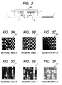
- the image read sensor 106 includes an LED 3 serving as light irradiation means, a CMOS sensor 4 serving as read means, lenses 5 and 6 which are imaging lenses, and so on. Then, a light from the LED 3 as a light source is irradiated onto the surface of a recording material transport guide 1 or the surface of the recording material P on the recording material transport guide (recording material transport path) 1 through the lens 5.
- a reflection light from the recording material P is converged by the lens 6 and imaged on the CMOS sensor 4.
- the surface image of the recording material transport guide 1 or the recording material P is read.
- the LED 3 is so arranged as to irradiate the LED light onto the surface of the recording material P obliquely with a given angle as shown in Fig. 2.
- Figs. 3A to 3F are diagrams showing a relationship between the surface of the recording sheet P which has been read by the CMOS sensor 4 of the image read sensor 106 and an example in which the output from the CMOS sensor 4 is digitized to 8 x 8 pixels, respectively.
- the digitizing process is conducted by transforming the analog output from the CMOS sensor 4 to pixel data of 8 bits by an A/D converter (not shown) serving as conversion means.
- Fig. 3A shows an enlarged image on the surface of a recording sheet A which is a so-called “rough paper” whose surface is relatively rough in paper fiber
- Fig. 3B shows an enlarged image on the surface of a recording sheet B which is a so-called “plain paper” which is commonly used
- Fig. 3C shows an enlarged image on the surface of a recording sheet C which is a gloss paper whose paper fibers have been sufficiently compressed, respectively.
- those images which are read by the CMOS sensor 4 are digitized into images shown in Figs. 3D, 3E and 3F.
- the images of the surface are different depending on the sheet type of the recording materials. This is a phenomenon that occurs mainly because the fiber state on the surface of the paper is different. Therefore, as described above, the image obtained by reading the recording material surface by the CMOS sensor 4 and digitizing the recording material surface can be judged by the surface state of the paper fiber of the recording material.
- a step S101 it is judged whether an image forming operation starts, or not, and in the case where the image forming operation starts, after the image forming operation on the recording material P starts, the recording material is transported and arrives at the pair of registration rollers 107, and waits until it becomes in a temporary stop state (hereinafter referred to as "standby before registration) for synchronous adjustment of the registration in a step S102.
- Whether the recording material P arrives at the pair of registration rollers 107, or not, is judged by monitoring the pre-registration sensor 108 by the DC controller 137.
- the LED 3 turns on in a step S103, and the image of the recording material P is read by the CMOS sensor 4 in a step S104.
- step S106 After the LED 33 turns off in a step S105, it is judged again in a step S106 that the recording material P is on standby before registration. This is because the image is again read in the case where the recording material P becomes in a transporting state during reading the image with the result that the image cannot be excellently read (blurring of the read image, or the like). Then, in the case where the recording material is on standby before registration in a step S106, an image comparison operation which will be described later is conducted in a step S107, and the type of sheet is judged on the basis of the image comparison operation result in a step S108.
- the process condition is set in accordance with the judged type of sheet in a step S109, the registration roller is rotated in a step S110, and the transportation of the recording material restarts.
- the recording material whose transportation restarts afterward, is transferred an image on the ITB 109 in the secondary transfer part (secondary transfer roller 122), and the image is fixed on the recording material before the recording material is discharged.
- the temperature of the fixing roller 124 is controlled in such a manner that if the type of sheet is, for example, the recording material A shown in Figs. 3A to 3F, whose surface paper fibers are rough is used, the fixing temperature is set to be higher, and if the type of sheet is the recording material C whose surface paper fibers are smooth, the fixing temperature is set to be lower.
- the pixel Dmax of the maximum density and the pixel Dmin of the minimum density are led from the result of reading the images at plural portions of the recording material surface. Then, this is executed for each of the read images, and an average processing is conducted. That is, in the case where the type of sheet whose surface paper fibers are rough as in the recording material A is used, the shadow of the fibers largely occurs. As a result, because a difference between a light portion and a dark portion is largely exhibited, Dmax - Dmin becomes large. On the other hand, in the case of the surface of the recording material C, the shadow of the fibers is small, and Dmax - Dmin becomes small. This comparison makes it possible to judge the type of sheet of the recording material.
- the image forming apparatus that judges the type of sheet by using the image pickup device such as the CMOS sensor 4 or the CCD sensor, since the LED 3 and the CMOS sensor 4 are arranged on the recording material transport guide 1, and the operation of reading the image of the recording material surface by the CMOS sensor 4 is conducted at the time of stopping the recording material P, the image that does not blur and is excellent in precision even if the shutter period of time of the image pickup device is made long.
- the LED 3 and the CMOS sensor 4 are disposed downstream of the junction of the recording material transport paths from the respective paper feed parts, thereby being capable of judging the type of sheet more inexpensively.
- Fig. 5 is a flowchart showing the control operation by an MPU 138 disposed in a DC controller 137 serving as read timing control means in accordance with this embodiment.
- a difference from the first embodiment resides in that the image read operation does not wait until the recording material P stops on standby before registration since the image forming operation starts, but at a time point where the paper feed part that feeds the recording material P is decided in a step S201; the recording material P is fed in a step S202, the recording material P is transported to a standby position before registration in a step S203, the recording material P is made on standby before registration in a step S204, and a sequence of operations including the operation of turning on the LED in the step S103 to the operation of judging the sheet type in the step S108 are conducted.
- the above control makes it possible to set a period of time during which the recording material P is made on standby before registration to be longer, and therefore it is possible to forcedly stop the recording material P before registration at the time of reading the image.
- the LED 3 and the MOS sensor 4 are disposed on the recording material transport guide 1, and the transportation of the recording material P stops at the time of reading the image of the recording material surface by the CMOS sensor 4, to thereby obtain the same effects as those in the above above-mentioned embodiment.
- the present invention in the image forming apparatus that judges the sheet type by using the image pickup device, it is possible to read an image that does not blur and is excellent in precision even if the shutter period of time of the image pickup device is made long.
Landscapes
- Physics & Mathematics (AREA)
- General Physics & Mathematics (AREA)
- Engineering & Computer Science (AREA)
- Microelectronics & Electronic Packaging (AREA)
- Control Or Security For Electrophotography (AREA)
- Controlling Sheets Or Webs (AREA)
- Image Input (AREA)
- Facsimiles In General (AREA)
- Record Information Processing For Printing (AREA)
Abstract
Description
Claims (11)
- An image forming apparatus, comprising:wherein the reading part is disposed along a transport path of the transporting part, anda transporting part for transporting a recording material;an image forming part for forming an image on the recording material transported by the transporting part;a reading part for reading a picture of a surface of the recording material; anda judging part for judging a type of the recording material on the basis of the picture of the surface of the recording material read by the reading part,
wherein the judging part judges the type of the recording material on the basis of the picture of the surface of the recording material read by the reading part during a period of time where the recording material stops in a midway through the transport path. - An image forming apparatus according to claim 1, wherein the reading part comprises a light emitting part for irradiating a light onto the recording material, and a light receiving part for receiving a reflection light from the recording material.
- An image forming apparatus according to claim 1, wherein the judging part judges the type of the recording material by calculating surface smoothness of the recording material on the basis of the picture of the surface of the recording material read by the reading part.
- An image forming apparatus according to claim 1, wherein the image bearing body comprises an intermediate transfer body.
- An image forming apparatus according to claim 1, further comprising control means for controlling a process condition on the basis of a judging result of the judging part.
- An image forming apparatus, comprising:wherein the reading part is disposed along a transport path of the transporting part, anda transporting part for transporting a recording material;an image forming part for forming an image on an image bearing body;a transfer part for transferring the image on the image bearing body to a recording paper which is transported by the transporting part;a synchronization controlling part for restarting the transport of the recording material after the recording material which is transported by the transporting part stops once in such a manner that the image on the image bearing body and the recording material are synchronous with each other;a reading part for reading a picture of a surface of the recording material; anda judging part for judging the type of a recording material on the basis of the picture of the surface of the recording material read by the reading part,
wherein the judging part judges the type of the recording material on the basis of the picture of the surface of the recording material read by the reading part during a period of time where the synchronization controlling part stops the recording material. - An image forming apparatus according to claim 6, wherein the reading part comprises a light emitting part that irradiates a light onto the recording material, and a light receiving part that receives a reflection light from the recording material.
- An image forming apparatus according to claim 6, wherein the judging part judges the type of the recording material by calculating surface smoothness of the recording material on the basis of the picture of the surface of the recording material read by the reading part.
- An image forming apparatus according to claim 6, wherein the image bearing body comprises an intermediate transfer body.
- An image forming apparatus according to claim 6, further comprising control means for controlling a process condition on the basis of a judging result of the judging part.
- An image forming apparatus according to claim 1, further comprising: a first sheet feeding part and a second sheet feeding part,
wherein the reading part is disposed downstream of a junction of the transport path from the first sheet feeding part and the transport path from the second sheet feeding part.
Priority Applications (1)
| Application Number | Priority Date | Filing Date | Title |
|---|---|---|---|
| EP09158235A EP2082887B1 (en) | 2002-04-12 | 2003-04-10 | Image forming apparatus |
Applications Claiming Priority (2)
| Application Number | Priority Date | Filing Date | Title |
|---|---|---|---|
| JP2002109923 | 2002-04-12 | ||
| JP2002109923A JP4289827B2 (en) | 2002-04-12 | 2002-04-12 | Image forming apparatus |
Related Child Applications (1)
| Application Number | Title | Priority Date | Filing Date |
|---|---|---|---|
| EP09158235A Division EP2082887B1 (en) | 2002-04-12 | 2003-04-10 | Image forming apparatus |
Publications (3)
| Publication Number | Publication Date |
|---|---|
| EP1354717A2 true EP1354717A2 (en) | 2003-10-22 |
| EP1354717A3 EP1354717A3 (en) | 2004-04-14 |
| EP1354717B1 EP1354717B1 (en) | 2009-07-01 |
Family
ID=28672535
Family Applications (2)
| Application Number | Title | Priority Date | Filing Date |
|---|---|---|---|
| EP03008360A Expired - Lifetime EP1354717B1 (en) | 2002-04-12 | 2003-04-10 | Image Forming Apparatus |
| EP09158235A Expired - Lifetime EP2082887B1 (en) | 2002-04-12 | 2003-04-10 | Image forming apparatus |
Family Applications After (1)
| Application Number | Title | Priority Date | Filing Date |
|---|---|---|---|
| EP09158235A Expired - Lifetime EP2082887B1 (en) | 2002-04-12 | 2003-04-10 | Image forming apparatus |
Country Status (6)
| Country | Link |
|---|---|
| US (1) | US7130573B2 (en) |
| EP (2) | EP1354717B1 (en) |
| JP (1) | JP4289827B2 (en) |
| KR (1) | KR100559277B1 (en) |
| CN (1) | CN1289984C (en) |
| DE (1) | DE60328144D1 (en) |
Families Citing this family (19)
| Publication number | Priority date | Publication date | Assignee | Title |
|---|---|---|---|---|
| JP4756227B2 (en) * | 2004-03-30 | 2011-08-24 | キヤノン株式会社 | Image forming apparatus |
| JP5506713B2 (en) * | 2004-03-30 | 2014-05-28 | キヤノン株式会社 | Recording material surface detection apparatus and image forming apparatus |
| US7695131B2 (en) | 2004-10-16 | 2010-04-13 | Samsung Electronics Co., Ltd. | Media detection apparatus and method usable with image forming apparatus |
| US7558492B2 (en) | 2005-07-29 | 2009-07-07 | Canon Kabushiki Kaisha | Image forming apparatus and image forming method |
| US7551306B2 (en) * | 2005-07-29 | 2009-06-23 | Canon Kabushiki Kaisha | Image forming apparatus and method for controlling the image forming apparatus |
| JP4709044B2 (en) * | 2006-03-27 | 2011-06-22 | キヤノン株式会社 | Sheet feeding apparatus and image forming apparatus |
| US7945177B2 (en) * | 2006-09-29 | 2011-05-17 | Canon Kabushiki Kaisha | Image forming apparatus with first and second settable resolution grades |
| US7865094B2 (en) * | 2007-02-23 | 2011-01-04 | Kabushiki Kaisha Toshiba | Image forming apparatus |
| US7636526B2 (en) * | 2007-03-16 | 2009-12-22 | Kabushiki Kaisha Toshiba | Image forming apparatus and control method thereof |
| JP5435984B2 (en) | 2008-03-31 | 2014-03-05 | キヤノン株式会社 | Image forming apparatus and image forming apparatus control method |
| JP2011079202A (en) * | 2009-10-06 | 2011-04-21 | Canon Inc | Recording medium detection device, and image forming apparatus |
| JP2014124833A (en) * | 2012-12-26 | 2014-07-07 | Kyocera Document Solutions Inc | Image forming apparatus |
| JP6288549B2 (en) * | 2013-10-24 | 2018-03-07 | 株式会社リコー | Optical sensor, image forming apparatus including the same, and apparatus and method for discriminating paper type |
| US9977999B2 (en) | 2014-01-06 | 2018-05-22 | Hewlett-Packard Development Company, L.P. | Paper classification based on three-dimensional characteristics |
| JP6398436B2 (en) | 2014-08-01 | 2018-10-03 | 株式会社リコー | Medium discriminating apparatus, image forming apparatus, medium discriminating method, and program |
| JP2018133742A (en) * | 2017-02-16 | 2018-08-23 | キヤノン株式会社 | Recording apparatus, inspection apparatus, and control method |
| JP7073786B2 (en) * | 2018-03-05 | 2022-05-24 | コニカミノルタ株式会社 | Image forming device, sheet type determination method, and computer program |
| JP2025042187A (en) * | 2023-09-14 | 2025-03-27 | キヤノン株式会社 | Sheet detection device and image formation device |
| JP2025042188A (en) * | 2023-09-14 | 2025-03-27 | キヤノン株式会社 | Paper detection device, image forming device |
Family Cites Families (15)
| Publication number | Priority date | Publication date | Assignee | Title |
|---|---|---|---|---|
| JP2673968B2 (en) | 1990-07-10 | 1997-11-05 | キヤノン株式会社 | Temperature control device |
| JP3610076B2 (en) | 1991-12-10 | 2005-01-12 | キヤノン株式会社 | Recording device |
| JP3302100B2 (en) | 1992-06-10 | 2002-07-15 | キヤノン株式会社 | Image recording device |
| KR0150146B1 (en) * | 1995-12-20 | 1998-12-01 | 김광호 | Control method of automatic adjusting transfer voltage in electrophotography developing type printer |
| US6421139B1 (en) | 1997-02-28 | 2002-07-16 | Canon Kabushiki Kaisha | Image forming apparatus for forming image on free-size sheet having arbitrary size |
| JPH10265088A (en) | 1997-03-26 | 1998-10-06 | Canon Inc | Image forming device |
| JP3919291B2 (en) | 1997-05-30 | 2007-05-23 | キヤノン株式会社 | Image forming apparatus |
| US5925889A (en) | 1997-10-21 | 1999-07-20 | Hewlett-Packard Company | Printer and method with media gloss and color determination |
| JP3406507B2 (en) | 1998-03-19 | 2003-05-12 | シャープ株式会社 | Image forming method and image forming apparatus |
| JPH11354254A (en) | 1998-06-10 | 1999-12-24 | Canon Inc | Heating device, fixing device, and image forming apparatus provided with the heating device |
| JP4323659B2 (en) * | 1999-02-16 | 2009-09-02 | キヤノン株式会社 | Image forming apparatus |
| US6291829B1 (en) | 1999-03-05 | 2001-09-18 | Hewlett-Packard Company | Identification of recording medium in a printer |
| JP2001213546A (en) | 2000-02-03 | 2001-08-07 | Canon Inc | Sheet wrap detecting device, fixing device, and image forming device |
| US6386676B1 (en) * | 2001-01-08 | 2002-05-14 | Hewlett-Packard Company | Reflective type media sensing methodology |
| US6497179B1 (en) * | 2001-07-19 | 2002-12-24 | Hewlett Packard Company | Method and apparatus for distinguishing transparent media |
-
2002
- 2002-04-12 JP JP2002109923A patent/JP4289827B2/en not_active Expired - Fee Related
-
2003
- 2003-04-09 US US10/409,472 patent/US7130573B2/en not_active Expired - Lifetime
- 2003-04-10 CN CNB031218024A patent/CN1289984C/en not_active Expired - Fee Related
- 2003-04-10 EP EP03008360A patent/EP1354717B1/en not_active Expired - Lifetime
- 2003-04-10 EP EP09158235A patent/EP2082887B1/en not_active Expired - Lifetime
- 2003-04-10 DE DE60328144T patent/DE60328144D1/en not_active Expired - Lifetime
- 2003-04-11 KR KR1020030022886A patent/KR100559277B1/en not_active Expired - Fee Related
Also Published As
| Publication number | Publication date |
|---|---|
| EP2082887A1 (en) | 2009-07-29 |
| JP2003302885A (en) | 2003-10-24 |
| JP4289827B2 (en) | 2009-07-01 |
| EP1354717B1 (en) | 2009-07-01 |
| KR100559277B1 (en) | 2006-03-15 |
| EP2082887B1 (en) | 2011-08-24 |
| EP1354717A3 (en) | 2004-04-14 |
| US7130573B2 (en) | 2006-10-31 |
| DE60328144D1 (en) | 2009-08-13 |
| CN1452031A (en) | 2003-10-29 |
| CN1289984C (en) | 2006-12-13 |
| US20030194252A1 (en) | 2003-10-16 |
| KR20030081158A (en) | 2003-10-17 |
Similar Documents
| Publication | Publication Date | Title |
|---|---|---|
| US7130573B2 (en) | Image forming apparatus | |
| US10365601B2 (en) | Image forming apparatus and image forming method | |
| US5043771A (en) | Image forming apparatus having a controller for controlling the registration rollers | |
| US10757280B2 (en) | Image reader, image forming apparatus, and image density correcting method | |
| JP5079609B2 (en) | Image reading apparatus and image forming apparatus | |
| JP6776714B2 (en) | Image forming system, image reading device, and image forming device | |
| US11290669B2 (en) | Image reading apparatus and image forming apparatus | |
| JP4372038B2 (en) | Image forming apparatus | |
| JP4756227B2 (en) | Image forming apparatus | |
| US7043170B2 (en) | Image forming apparatus having speed control of primary and secondary image transfers | |
| US9531913B1 (en) | Image processing apparatus and method for generating correction formula | |
| US9179012B2 (en) | Image reading apparatus, image forming apparatus, image reading method and recording medium that ensure simplified detection of noise mixed in image signal | |
| US7551320B2 (en) | Image processing apparatus, image forming apparatus, control program, and computer-readable recording medium | |
| JP4861442B2 (en) | Image forming apparatus | |
| US6842589B2 (en) | Method and image forming apparatus producing toner pattern without adhesion of toner to separation pick | |
| KR100572293B1 (en) | Image forming apparatus | |
| JP2006293144A (en) | Sheet material detection apparatus and image forming apparatus | |
| JP2008032848A (en) | Paper surface property detection sensor and image forming apparatus having the same | |
| US20240348729A1 (en) | Image reading device, image forming apparatus, and image reading method | |
| JP2004085787A (en) | Image forming device | |
| JP2002187641A (en) | Image forming device | |
| JP2007208672A (en) | Original reading apparatus, image forming apparatus and original reading method | |
| JP4254082B2 (en) | Image processing device | |
| JP2004093967A (en) | Image forming apparatus and method | |
| JPH01296274A (en) | Color image forming device |
Legal Events
| Date | Code | Title | Description |
|---|---|---|---|
| PUAI | Public reference made under article 153(3) epc to a published international application that has entered the european phase |
Free format text: ORIGINAL CODE: 0009012 |
|
| AK | Designated contracting states |
Kind code of ref document: A2 Designated state(s): AT BE BG CH CY CZ DE DK EE ES FI FR GB GR HU IE IT LI LU MC NL PT SE SI SK TR |
|
| AX | Request for extension of the european patent |
Extension state: AL LT LV MK RO |
|
| PUAL | Search report despatched |
Free format text: ORIGINAL CODE: 0009013 |
|
| AK | Designated contracting states |
Kind code of ref document: A3 Designated state(s): AT BE BG CH CY CZ DE DK EE ES FI FR GB GR HU IE IT LI LU MC NL PT SE SI SK TR |
|
| AX | Request for extension of the european patent |
Extension state: AL LT LV MK RO |
|
| 17P | Request for examination filed |
Effective date: 20040817 |
|
| AKX | Designation fees paid |
Designated state(s): DE FR GB |
|
| 17Q | First examination report despatched |
Effective date: 20060518 |
|
| GRAP | Despatch of communication of intention to grant a patent |
Free format text: ORIGINAL CODE: EPIDOSNIGR1 |
|
| GRAS | Grant fee paid |
Free format text: ORIGINAL CODE: EPIDOSNIGR3 |
|
| GRAA | (expected) grant |
Free format text: ORIGINAL CODE: 0009210 |
|
| AK | Designated contracting states |
Kind code of ref document: B1 Designated state(s): DE FR GB |
|
| REG | Reference to a national code |
Ref country code: GB Ref legal event code: FG4D |
|
| REF | Corresponds to: |
Ref document number: 60328144 Country of ref document: DE Date of ref document: 20090813 Kind code of ref document: P |
|
| PLBE | No opposition filed within time limit |
Free format text: ORIGINAL CODE: 0009261 |
|
| STAA | Information on the status of an ep patent application or granted ep patent |
Free format text: STATUS: NO OPPOSITION FILED WITHIN TIME LIMIT |
|
| 26N | No opposition filed |
Effective date: 20100406 |
|
| REG | Reference to a national code |
Ref country code: FR Ref legal event code: PLFP Year of fee payment: 14 |
|
| REG | Reference to a national code |
Ref country code: FR Ref legal event code: PLFP Year of fee payment: 15 |
|
| REG | Reference to a national code |
Ref country code: FR Ref legal event code: PLFP Year of fee payment: 16 |
|
| PGFP | Annual fee paid to national office [announced via postgrant information from national office to epo] |
Ref country code: FR Payment date: 20180426 Year of fee payment: 16 |
|
| PGFP | Annual fee paid to national office [announced via postgrant information from national office to epo] |
Ref country code: DE Payment date: 20180629 Year of fee payment: 16 Ref country code: GB Payment date: 20180427 Year of fee payment: 16 |
|
| REG | Reference to a national code |
Ref country code: DE Ref legal event code: R119 Ref document number: 60328144 Country of ref document: DE |
|
| GBPC | Gb: european patent ceased through non-payment of renewal fee |
Effective date: 20190410 |
|
| PG25 | Lapsed in a contracting state [announced via postgrant information from national office to epo] |
Ref country code: DE Free format text: LAPSE BECAUSE OF NON-PAYMENT OF DUE FEES Effective date: 20191101 Ref country code: GB Free format text: LAPSE BECAUSE OF NON-PAYMENT OF DUE FEES Effective date: 20190410 |
|
| PG25 | Lapsed in a contracting state [announced via postgrant information from national office to epo] |
Ref country code: FR Free format text: LAPSE BECAUSE OF NON-PAYMENT OF DUE FEES Effective date: 20190430 |