EP1354706A1 - Drop-on-demand liquid emission using interconnected dual electrodes as ejection device - Google Patents
Drop-on-demand liquid emission using interconnected dual electrodes as ejection device Download PDFInfo
- Publication number
- EP1354706A1 EP1354706A1 EP03075998A EP03075998A EP1354706A1 EP 1354706 A1 EP1354706 A1 EP 1354706A1 EP 03075998 A EP03075998 A EP 03075998A EP 03075998 A EP03075998 A EP 03075998A EP 1354706 A1 EP1354706 A1 EP 1354706A1
- Authority
- EP
- European Patent Office
- Prior art keywords
- electrode
- emission device
- electrodes
- drop
- addressable
- Prior art date
- Legal status (The legal status is an assumption and is not a legal conclusion. Google has not performed a legal analysis and makes no representation as to the accuracy of the status listed.)
- Granted
Links
- 239000007788 liquid Substances 0.000 title claims abstract description 44
- 230000009977 dual effect Effects 0.000 title abstract description 4
- 238000005452 bending Methods 0.000 claims description 3
- 230000007423 decrease Effects 0.000 claims description 2
- 238000005381 potential energy Methods 0.000 abstract description 7
- 230000009471 action Effects 0.000 abstract description 3
- 239000000976 ink Substances 0.000 description 11
- 230000007246 mechanism Effects 0.000 description 9
- 230000005684 electric field Effects 0.000 description 3
- 239000012530 fluid Substances 0.000 description 3
- 238000000034 method Methods 0.000 description 3
- 230000002093 peripheral effect Effects 0.000 description 2
- 230000009467 reduction Effects 0.000 description 2
- 230000015572 biosynthetic process Effects 0.000 description 1
- 239000004020 conductor Substances 0.000 description 1
- 238000006073 displacement reaction Methods 0.000 description 1
- 230000002708 enhancing effect Effects 0.000 description 1
- 238000007641 inkjet printing Methods 0.000 description 1
- 238000004519 manufacturing process Methods 0.000 description 1
- 230000004048 modification Effects 0.000 description 1
- 238000012986 modification Methods 0.000 description 1
- 238000007639 printing Methods 0.000 description 1
- 230000008569 process Effects 0.000 description 1
- 238000000926 separation method Methods 0.000 description 1
Images



Classifications
-
- B—PERFORMING OPERATIONS; TRANSPORTING
- B41—PRINTING; LINING MACHINES; TYPEWRITERS; STAMPS
- B41J—TYPEWRITERS; SELECTIVE PRINTING MECHANISMS, i.e. MECHANISMS PRINTING OTHERWISE THAN FROM A FORME; CORRECTION OF TYPOGRAPHICAL ERRORS
- B41J2/00—Typewriters or selective printing mechanisms characterised by the printing or marking process for which they are designed
- B41J2/005—Typewriters or selective printing mechanisms characterised by the printing or marking process for which they are designed characterised by bringing liquid or particles selectively into contact with a printing material
- B41J2/01—Ink jet
- B41J2/135—Nozzles
- B41J2/14—Structure thereof only for on-demand ink jet heads
- B41J2/14314—Structure of ink jet print heads with electrostatically actuated membrane
Definitions
- the present invention relates generally to drop-on-demand liquid emission devices such as, for example, ink jet printers, and more particularly such devices which employ an electrostatic actuator for driving liquid from the device.
- DOD liquid emission devices with electrostatic actuators are known for ink printing systems.
- U.S. Patents No. 5,644,341 and No. 5,668,579 which issued to Fujii et al. on July 1, 1997 and September 16, 1997, respectively, disclose such devices having electrostatic actuators composed of a diaphragm and opposed electrode. The diaphragm is distorted by application of a first voltage to the electrode. Relaxation of the diaphragm expels an ink droplet from the device.
- Other devices that operate on the principle of electrostatic attraction are disclosed in U.S. Patents No. 5,739,831, No. 6,127,198, and No. 6,318,841; and in U.S. Pub. No. 2001/0023523.
- an electrostatic attraction force is applied in a single direction, as the electrodes can only attract; repulsion being impossible.
- the devices must rely on the elastic memory of the diaphragm to return to an at-rest position.
- large electrodes are required, and the gap between electrodes needs to be small. These two criteria are difficult to achieve while still providing for sufficient displacement to expel a reasonably sized droplet.
- Another drawback of large electrodes is the poor spatial resolution between nozzles.
- a drop-on-demand liquid emission device such as for example an ink jet printer, includes an electrostatic drop ejection mechanism that employs an electric field for driving liquid from the device.
- Structurally coupled, separately addressable dual electrodes greatly enhance the fundamental efficiency of the electrostatic drop ejection mechanism.
- the increased efficiency of the electrostatic drop ejection mechanism enables a reduction of electrode size (area) and reduces the required electrode voltage.
- the liquid emission device includes a liquid chamber having a nozzle orifice.
- Separately addressable dual electrodes are positioned on opposite sides of a single ground electrode such that the three electrodes are generally axially aligned with the nozzle orifice.
- the ground electrode is structurally stiff, and the two addressable electrodes are structurally connected via a rigid, electrically insulating coupler.
- an electrostatic charge is applied to the addressable electrode nearest to the nozzle orifice, which pulls that electrode toward the ground electrode and away from the orifice.
- This electrode forms a wall portion of the liquid chamber behind the nozzle orifice, so that movement of this electrode away from the nozzle expands the chamber, drawing liquid into the expanding chamber.
- the other addressable electrode moves in conjunction, storing elastic potential energy in the system. Subsequently the addressable electrode nearest to the nozzle is de-energized and the other addressable electrode is energized, causing the other electrode to be pulled toward the ground electrode in conjunction with the release of the stored elastic potential energy. This action pressurizes the liquid in the chamber behind the nozzle orifice, causing a drop to be ejected from the nozzle orifice.
- the efficiency of the electrostatic drop ejection mechanism will be increased.
- the force applied during the final stages of drop ejection and separation will be positive and controllable such that the risk of satellite formation is substantially reduced. Since there is no electric field across the ink, conductive inks and other liquids can be used. Also, the electric field can be across air or other dielectric fluid, enhancing the electrostatic performance of the system.
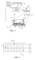
- FIG. 1 is a schematic illustration of a drop-on-demand liquid emission device according to the present invention
- the present invention provides an apparatus and method of operating a drop-on-demand liquid emission device.
- the most familiar of such devices are used as printheads in ink jet printing systems.
- Many other applications are emerging which make use of devices similar to ink jet printheads, but which emit liquids (other than inks) that need to be finely metered and deposited with high spatial precision.
- the inventions described below provide apparatus and methods for operating drop emitters based on electrostatic actuators so as to improve energy efficiency and overall drop emission productivity.
- FIG. 1 shows a schematic representation of a drop-on-demand liquid emission device 10, such as an ink jet printer, which may be operated according to the present invention.
- the system includes a source 12 of data (say, image data) which provides signals that are interpreted by a controller 14 as being commands to emit drops.
- Controller 14 outputs signals to a source 16 of electrical energy pulses which are inputted to a drop-on-demand liquid emission device such as an ink jet printer 18.
- Drop-on-demand liquid emission device 10 includes a plurality of electrostatic drop ejection mechanisms 20.
- FIG. 2 is a cross-sectional view of one of the plurality of electrostatically actuated drop ejection mechanisms 20.
- a nozzle orifice 22 is formed in a nozzle plate 24 for each mechanism 20.
- a wall or walls 26 that carry an electrically addressable electrode 28 bound each drop ejection mechanism 20.
- the outer periphery of electrode 28 is sealingly attached to wall 26 to define a liquid chamber 30 adapted to receive the liquid, such as for example ink, to be ejected from nozzle orifice 22.
- the liquid is drawn into chamber 30 through one or more ports 32 from a supply, not shown. Ports 32 are sized as discussed below.
- Dielectric fluid fills the region 34 on the side of electrode 28 opposed to chamber 30.
- the dielectric fluid is preferably air or other dielectric gas, although a dielectric liquid may be used.
- a second electrode 36 is electrically addressable separately from electrode 28.
- Addressable electrodes 28 and 36 are preferably at least partially flexible and are positioned on opposite sides of a single ground electrode 38 such that the three electrodes are generally axially aligned with nozzle orifice 22.
- Addressable electrode 36 is illustrated with a peripheral region that has enhanced flexibility. Since there is no need for addressable electrode to completely seal with wall 26, the peripheral region may by mere tabs tethering the central region of electrode 36 to wall 26.
- Ground electrode 38 is structurally stiff, and the two addressable electrodes are structurally connected via a rigid coupler 40.
- This coupler is electrically insulating, which term is intended to include a coupler of conductive material but having a non-conductive break therein. Coupler 40 ties the two addressable electrodes structurally together and insolates the electrodes so as to make possible distinct charges on the two.
- FIGS. 3-5 are top plan views of nozzle plate 24, showing several alternative embodiments of layout patterns for the several nozzle orifices 22 of a print head. Note that in FIGS. 2 and 3, the interior surface of walls 26 are annular, while in FIG. 5, walls 26 form rectangular chambers. Other shapes are of course possible, and these drawings are merely intended to convey the understanding that alternatives are possible within the spirit and scope of the present invention.
- an electrostatic charge is applied to the addressable electrode 28 nearest to nozzle orifice 22, which pulls that electrode toward ground electrode 38 and away from the nozzle orifice. Since this electrode forms a wall portion of liquid chamber 30 behind the nozzle orifice, movement of electrode 28 away from nozzle plate 24 expands the chamber, drawing liquid into the expanding chamber through ports 32.
- Addressable electrode 36 does not receive an electrostatic charge, and moves in conjunction with addressable electrode 28, storing elastic potential energy in the system.
- addressable electrode 28 is de-energized and addressable electrode 36 is energized, causing addressable electrode 36 to be pulled toward ground electrode 38 in conjunction with the release of the stored elastic potential energy.
- the timing of the deenergization of electrode 28 and the engization of electrode 36 may be simultaneous, or there may be a short dwell period therebetween so that the structure begins to move from the position illustrated in FIG. 6 toward the position illustrated in FIG. 7 under the sole force of stored elastic potential energy in the system. Still referring to FIG. 7, this action pressurizes the liquid in chamber 30 behind the nozzle orifice, causing a drop to be ejected from the nozzle orifice.
- ports 32 should be properly sized to present sufficiently low flow resistance so that filling of chamber 30 is not significantly impeded when electrode 28 is energized, and yet present sufficiently high resistance to the back flow of liquid through the port during drop ejection.
- the center region of addressable electrode 36 is preferably structurally rigid so as to resist bending. In this manner, substantially all of the energy produced when it is addressed is transferred through coupler 40 to electrode 28.
- the central region of electrode 28 may also be rigid.
- the gap "A" between addressable electrode 28 and ground electrode 38 is large relative to gap “B” between addressable electrode 36 and ground electrode 38.
- Large gap “A” provides for sufficient movement of electrode 28 to load a large quantity of liquid into chamber 30 when an electrostatic charge is applied to addressable electrode 28 to pull that electrode toward ground electrode 38.
- electrode 36 does not travel too far from ground electrode 38 during the loading process to produce sufficient attractive force when an electrostatic charge is applied to addressable electrode 36.
- electrode 36 could initially be in actual contact with ground electrode 38, but this is not believed to be preferred since some movement beyond the position shown in FIG. 2 during drop ejection so that the return movement towards the rest position can be used to draw liquid into chamber 30.
- each nozzle orifice 22 may be provided with a drop ejection mechanism 20' as illustrated in FIG. 8, wherein a plurality of electrode sets are attached to a single coupler 40' should additional ejection force be desired.
- Each electrode set includes an electrically-addressable electrode 28', but only the electrode 28' nearest to nozzle orifice 22 needs to be sealingly attached to wall 26 to define a liquid chamber 30.
- a second electrode 36' of each electrode set is electrically addressable separately from electrode 28'.
- a ground electrode 38' completes each electrode set.
- One or more of the electrode sets can be actuated at a time to provide an adjustable amount of drop ejection force.
Landscapes
- Particle Formation And Scattering Control In Inkjet Printers (AREA)
Abstract
Description
- The present invention relates generally to drop-on-demand liquid emission devices such as, for example, ink jet printers, and more particularly such devices which employ an electrostatic actuator for driving liquid from the device.
- Drop-on-demand (DOD) liquid emission devices with electrostatic actuators are known for ink printing systems. U.S. Patents No. 5,644,341 and No. 5,668,579, which issued to Fujii et al. on July 1, 1997 and September 16, 1997, respectively, disclose such devices having electrostatic actuators composed of a diaphragm and opposed electrode. The diaphragm is distorted by application of a first voltage to the electrode. Relaxation of the diaphragm expels an ink droplet from the device. Other devices that operate on the principle of electrostatic attraction are disclosed in U.S. Patents No. 5,739,831, No. 6,127,198, and No. 6,318,841; and in U.S. Pub. No. 2001/0023523.
- According to the prior art, an electrostatic attraction force is applied in a single direction, as the electrodes can only attract; repulsion being impossible.
Thus, the devices must rely on the elastic memory of the diaphragm to return to an at-rest position. In order to produce sufficient force, large electrodes are required, and the gap between electrodes needs to be small. These two criteria are difficult to achieve while still providing for sufficient displacement to expel a reasonably sized droplet. Another drawback of large electrodes is the poor spatial resolution between nozzles. - Devices that rely on the elastic memory of the diaphragm to expel liquid drops exhibit a reduction on the force over the time that liquid is being expelled. That is, the speed at which the diaphragm moves as it approached its at-rest position decreases. The result is a tendency toward the production of undesirable satellite droplets accompanying the main drop.
- According to a feature of the present invention, a drop-on-demand liquid emission device, such as for example an ink jet printer, includes an electrostatic drop ejection mechanism that employs an electric field for driving liquid from the device. Structurally coupled, separately addressable dual electrodes greatly enhance the fundamental efficiency of the electrostatic drop ejection mechanism. The increased efficiency of the electrostatic drop ejection mechanism enables a reduction of electrode size (area) and reduces the required electrode voltage.
- The liquid emission device includes a liquid chamber having a nozzle orifice. Separately addressable dual electrodes are positioned on opposite sides of a single ground electrode such that the three electrodes are generally axially aligned with the nozzle orifice. The ground electrode is structurally stiff, and the two addressable electrodes are structurally connected via a rigid, electrically insulating coupler. To eject a drop, an electrostatic charge is applied to the addressable electrode nearest to the nozzle orifice, which pulls that electrode toward the ground electrode and away from the orifice. This electrode forms a wall portion of the liquid chamber behind the nozzle orifice, so that movement of this electrode away from the nozzle expands the chamber, drawing liquid into the expanding chamber. The other addressable electrode moves in conjunction, storing elastic potential energy in the system. Subsequently the addressable electrode nearest to the nozzle is de-energized and the other addressable electrode is energized, causing the other electrode to be pulled toward the ground electrode in conjunction with the release of the stored elastic potential energy. This action pressurizes the liquid in the chamber behind the nozzle orifice, causing a drop to be ejected from the nozzle orifice.
- There are several advantages associated with the present invention. The efficiency of the electrostatic drop ejection mechanism will be increased. The force applied during the final stages of drop ejection and separation will be positive and controllable such that the risk of satellite formation is substantially reduced. Since there is no electric field across the ink, conductive inks and other liquids can be used. Also, the electric field can be across air or other dielectric fluid, enhancing the electrostatic performance of the system.
- FIG. 1 is a schematic illustration of a drop-on-demand liquid emission device according to the present invention;
- FIG. 2 is a cross-sectional view of a portion of drop-on-demand liquid emission device of FIG. 1;
- FIGS. 3-5 are top plan views of alternative embodiments of a nozzle plate of the drop-on-demand liquid emission device of FIGS. 1 and 2;
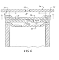
- FIG. 6 is a cross-sectional view of the drop-on-demand liquid emission device of FIG. 2 shown in a first actuation stage;
- FIG. 7 is a cross-sectional view of the drop-on-demand liquid emission device of FIG. 2 shown in a second actuation stage; and
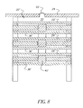
- FIG. 8 is a cross-sectional view of a portion of another embodiment of the drop-on-demand liquid emission device of FIG. 1.
-
- The invention has been described in detail with particular reference to certain preferred embodiments thereof, but it will be understood that variations and modifications can be effected within the spirit and scope of the invention.
- As described in detail herein below, the present invention provides an apparatus and method of operating a drop-on-demand liquid emission device. The most familiar of such devices are used as printheads in ink jet printing systems. Many other applications are emerging which make use of devices similar to ink jet printheads, but which emit liquids (other than inks) that need to be finely metered and deposited with high spatial precision. The inventions described below provide apparatus and methods for operating drop emitters based on electrostatic actuators so as to improve energy efficiency and overall drop emission productivity.
- FIG. 1 shows a schematic representation of a drop-on-demand
liquid emission device 10, such as an ink jet printer, which may be operated according to the present invention. The system includes asource 12 of data (say, image data) which provides signals that are interpreted by acontroller 14 as being commands to emit drops.Controller 14 outputs signals to asource 16 of electrical energy pulses which are inputted to a drop-on-demand liquid emission device such as anink jet printer 18. - Drop-on-demand
liquid emission device 10 includes a plurality of electrostaticdrop ejection mechanisms 20. FIG. 2 is a cross-sectional view of one of the plurality of electrostatically actuateddrop ejection mechanisms 20. Anozzle orifice 22 is formed in anozzle plate 24 for eachmechanism 20. A wall orwalls 26 that carry an electricallyaddressable electrode 28 bound eachdrop ejection mechanism 20. The outer periphery ofelectrode 28 is sealingly attached towall 26 to define aliquid chamber 30 adapted to receive the liquid, such as for example ink, to be ejected fromnozzle orifice 22. The liquid is drawn intochamber 30 through one ormore ports 32 from a supply, not shown.Ports 32 are sized as discussed below. Dielectric fluid fills theregion 34 on the side ofelectrode 28 opposed tochamber 30. The dielectric fluid is preferably air or other dielectric gas, although a dielectric liquid may be used. - A
second electrode 36 is electrically addressable separately fromelectrode 28.Addressable electrodes single ground electrode 38 such that the three electrodes are generally axially aligned withnozzle orifice 22.Addressable electrode 36 is illustrated with a peripheral region that has enhanced flexibility. Since there is no need for addressable electrode to completely seal withwall 26, the peripheral region may by mere tabs tethering the central region ofelectrode 36 towall 26. -
Ground electrode 38 is structurally stiff, and the two addressable electrodes are structurally connected via arigid coupler 40. This coupler is electrically insulating, which term is intended to include a coupler of conductive material but having a non-conductive break therein.Coupler 40 ties the two addressable electrodes structurally together and insolates the electrodes so as to make possible distinct charges on the two. - FIGS. 3-5 are top plan views of
nozzle plate 24, showing several alternative embodiments of layout patterns for theseveral nozzle orifices 22 of a print head. Note that in FIGS. 2 and 3, the interior surface ofwalls 26 are annular, while in FIG. 5,walls 26 form rectangular chambers. Other shapes are of course possible, and these drawings are merely intended to convey the understanding that alternatives are possible within the spirit and scope of the present invention. - Referring to FIG. 6, to eject a drop, an electrostatic charge is applied to the
addressable electrode 28 nearest tonozzle orifice 22, which pulls that electrode towardground electrode 38 and away from the nozzle orifice. Since this electrode forms a wall portion ofliquid chamber 30 behind the nozzle orifice, movement ofelectrode 28 away fromnozzle plate 24 expands the chamber, drawing liquid into the expanding chamber throughports 32.Addressable electrode 36 does not receive an electrostatic charge, and moves in conjunction withaddressable electrode 28, storing elastic potential energy in the system. - Subsequently (say, several microseconds later)
addressable electrode 28 is de-energized andaddressable electrode 36 is energized, causingaddressable electrode 36 to be pulled towardground electrode 38 in conjunction with the release of the stored elastic potential energy. The timing of the deenergization ofelectrode 28 and the engization ofelectrode 36 may be simultaneous, or there may be a short dwell period therebetween so that the structure begins to move from the position illustrated in FIG. 6 toward the position illustrated in FIG. 7 under the sole force of stored elastic potential energy in the system. Still referring to FIG. 7, this action pressurizes the liquid inchamber 30 behind the nozzle orifice, causing a drop to be ejected from the nozzle orifice. To optimize both refill and drop ejection,ports 32 should be properly sized to present sufficiently low flow resistance so that filling ofchamber 30 is not significantly impeded whenelectrode 28 is energized, and yet present sufficiently high resistance to the back flow of liquid through the port during drop ejection. - The center region of
addressable electrode 36 is preferably structurally rigid so as to resist bending. In this manner, substantially all of the energy produced when it is addressed is transferred throughcoupler 40 toelectrode 28. The central region ofelectrode 28 may also be rigid. - Referring to FIG. 2, the gap "A" between
addressable electrode 28 andground electrode 38 is large relative to gap "B" betweenaddressable electrode 36 andground electrode 38. Large gap "A" provides for sufficient movement ofelectrode 28 to load a large quantity of liquid intochamber 30 when an electrostatic charge is applied toaddressable electrode 28 to pull that electrode towardground electrode 38. By providing a small initial gap "B",electrode 36 does not travel too far fromground electrode 38 during the loading process to produce sufficient attractive force when an electrostatic charge is applied toaddressable electrode 36. In fact,electrode 36 could initially be in actual contact withground electrode 38, but this is not believed to be preferred since some movement beyond the position shown in FIG. 2 during drop ejection so that the return movement towards the rest position can be used to draw liquid intochamber 30. - It is contemplated that each
nozzle orifice 22 may be provided with a drop ejection mechanism 20' as illustrated in FIG. 8, wherein a plurality of electrode sets are attached to a single coupler 40' should additional ejection force be desired. Each electrode set includes an electrically-addressable electrode 28', but only theelectrode 28' nearest tonozzle orifice 22 needs to be sealingly attached to wall 26 to define aliquid chamber 30. A second electrode 36' of each electrode set is electrically addressable separately fromelectrode 28'. A ground electrode 38' completes each electrode set. One or more of the electrode sets can be actuated at a time to provide an adjustable amount of drop ejection force.
Claims (10)
- An emission device (10) for ejecting a liquid drop, said device comprising:a structure defining a chamber (30) volume adapted to receive a liquid and having a nozzle orifice (22) through which a drop of received liquid can be emitted;an actuator having:a first electrode (28) associated with a movable wall portion of the chamber volume defining structure such that electrical actuation of the first electrode moves the movable wall portion in a direction to increase the chamber volume to draw liquid into the chamber volume, anda second electrode (36) associated with the movable wall portion such that electrical actuation of the second electrode moves the movable wall portion in a direction to decrease the chamber volume to emit a liquid drop through the nozzle orifice; anda controller (14) adapted to selectively electrically actuate the first and second electrodes.
- An emission device as defined in Claim 1, wherein the moveable wall portion is disposed in the chamber volume defining structure in opposed alignment with the nozzle orifice.
- An emission device as defined in Claim 1, wherein the controller is adapted to de-actuate said first electrode before actuating said second electrode.
- An emission device as defined in Claim 3, wherein the controller is adapted not to actuate said second electrode until a short dwell period has passed after de-actuation of said first electrode.
- An emission device as defined in Claim 1, wherein the controller is adapted to simultaneously de-actuate said first electrode and actuate said second electrode.
- An emission device as defined in Claim 1, further comprising:a ground electrode positioned between said first electrode and said second electrode.
- An emission device as defined in Claim 1, wherein said first and second electrodes are structurally connected by a rigid coupler.
- An emission device as defined in Claim 1, wherein a center region of one of said first and second electrodes is structural rigid so as to resist bending.
- An emission device as defined in Claim 1, wherein a center region of both said first and second electrodes is structural rigid so as to resist bending.
- An emission device as defined in Claim 1, wherein one of said first and second electrodes is closer to the ground electrode than is the other of said first and second electrodes.
Applications Claiming Priority (2)
| Application Number | Priority Date | Filing Date | Title |
|---|---|---|---|
| US10/122,566 US6527373B1 (en) | 2002-04-15 | 2002-04-15 | Drop-on-demand liquid emission using interconnected dual electrodes as ejection device |
| US122566 | 2002-04-15 |
Publications (2)
| Publication Number | Publication Date |
|---|---|
| EP1354706A1 true EP1354706A1 (en) | 2003-10-22 |
| EP1354706B1 EP1354706B1 (en) | 2006-10-04 |
Family
ID=22403455
Family Applications (1)
| Application Number | Title | Priority Date | Filing Date |
|---|---|---|---|
| EP03075998A Expired - Lifetime EP1354706B1 (en) | 2002-04-15 | 2003-04-04 | Drop-on-demand liquid emission using interconnected dual electrodes as ejection device |
Country Status (3)
| Country | Link |
|---|---|
| US (1) | US6527373B1 (en) |
| EP (1) | EP1354706B1 (en) |
| DE (1) | DE60308743T2 (en) |
Cited By (2)
| Publication number | Priority date | Publication date | Assignee | Title |
|---|---|---|---|---|
| EP1393909A1 (en) * | 2002-08-26 | 2004-03-03 | Eastman Kodak Company | Drop-on-demand liquid emission using symmetrical electrostatic device |
| WO2007135595A1 (en) | 2006-05-19 | 2007-11-29 | Koninklijke Philips Electronics N.V. | Electrostatic actuator for ink jet heads |
Families Citing this family (4)
| Publication number | Priority date | Publication date | Assignee | Title |
|---|---|---|---|---|
| JP4954376B2 (en) * | 2001-01-15 | 2012-06-13 | パナソニック株式会社 | Liquid ejector |
| US6715704B2 (en) * | 2002-05-23 | 2004-04-06 | Eastman Kodak Company | Drop-on-demand liquid emission using asymmetrical electrostatic device |
| US6830701B2 (en) * | 2002-07-09 | 2004-12-14 | Eastman Kodak Company | Method for fabricating microelectromechanical structures for liquid emission devices |
| US7334871B2 (en) * | 2004-03-26 | 2008-02-26 | Hewlett-Packard Development Company, L.P. | Fluid-ejection device and methods of forming same |
Citations (7)
| Publication number | Priority date | Publication date | Assignee | Title |
|---|---|---|---|---|
| US4584590A (en) * | 1982-05-28 | 1986-04-22 | Xerox Corporation | Shear mode transducer for drop-on-demand liquid ejector |
| US4939405A (en) * | 1987-12-28 | 1990-07-03 | Misuzuerie Co. Ltd. | Piezo-electric vibrator pump |
| US5933169A (en) * | 1995-04-06 | 1999-08-03 | Brother Kogyo Kabushiki Kaisha | Two actuator shear mode type ink jet print head with bridging electrode |
| US6113209A (en) * | 1995-12-14 | 2000-09-05 | Toshiba Tec Kabushiki Kaisha | Driving device for electrostrictive ink-jet printer head having control circuit with switching elements for setting electrical potential ranges of power supply to electrodes of the printer head |
| US6290339B1 (en) * | 1998-07-22 | 2001-09-18 | Eastman Kodak Company | Method of directing fluid between a reservoir and a micro-orifice manifold |
| US6318841B1 (en) * | 1998-10-15 | 2001-11-20 | Xerox Corporation | Fluid drop ejector |
| US6351879B1 (en) * | 1998-08-31 | 2002-03-05 | Eastman Kodak Company | Method of making a printing apparatus |
Family Cites Families (6)
| Publication number | Priority date | Publication date | Assignee | Title |
|---|---|---|---|---|
| US4520375A (en) | 1983-05-13 | 1985-05-28 | Eaton Corporation | Fluid jet ejector |
| US5668579A (en) | 1993-06-16 | 1997-09-16 | Seiko Epson Corporation | Apparatus for and a method of driving an ink jet head having an electrostatic actuator |
| US5644341A (en) | 1993-07-14 | 1997-07-01 | Seiko Epson Corporation | Ink jet head drive apparatus and drive method, and a printer using these |
| JP3303901B2 (en) | 1994-09-16 | 2002-07-22 | セイコーエプソン株式会社 | Electric field drive type ink jet recording head and driving method thereof |
| US6662448B2 (en) | 1998-10-15 | 2003-12-16 | Xerox Corporation | Method of fabricating a micro-electro-mechanical fluid ejector |
| US6127198A (en) | 1998-10-15 | 2000-10-03 | Xerox Corporation | Method of fabricating a fluid drop ejector |
-
2002
- 2002-04-15 US US10/122,566 patent/US6527373B1/en not_active Expired - Fee Related
-
2003
- 2003-04-04 DE DE60308743T patent/DE60308743T2/en not_active Expired - Lifetime
- 2003-04-04 EP EP03075998A patent/EP1354706B1/en not_active Expired - Lifetime
Patent Citations (7)
| Publication number | Priority date | Publication date | Assignee | Title |
|---|---|---|---|---|
| US4584590A (en) * | 1982-05-28 | 1986-04-22 | Xerox Corporation | Shear mode transducer for drop-on-demand liquid ejector |
| US4939405A (en) * | 1987-12-28 | 1990-07-03 | Misuzuerie Co. Ltd. | Piezo-electric vibrator pump |
| US5933169A (en) * | 1995-04-06 | 1999-08-03 | Brother Kogyo Kabushiki Kaisha | Two actuator shear mode type ink jet print head with bridging electrode |
| US6113209A (en) * | 1995-12-14 | 2000-09-05 | Toshiba Tec Kabushiki Kaisha | Driving device for electrostrictive ink-jet printer head having control circuit with switching elements for setting electrical potential ranges of power supply to electrodes of the printer head |
| US6290339B1 (en) * | 1998-07-22 | 2001-09-18 | Eastman Kodak Company | Method of directing fluid between a reservoir and a micro-orifice manifold |
| US6351879B1 (en) * | 1998-08-31 | 2002-03-05 | Eastman Kodak Company | Method of making a printing apparatus |
| US6318841B1 (en) * | 1998-10-15 | 2001-11-20 | Xerox Corporation | Fluid drop ejector |
Cited By (6)
| Publication number | Priority date | Publication date | Assignee | Title |
|---|---|---|---|---|
| EP1393909A1 (en) * | 2002-08-26 | 2004-03-03 | Eastman Kodak Company | Drop-on-demand liquid emission using symmetrical electrostatic device |
| WO2007135595A1 (en) | 2006-05-19 | 2007-11-29 | Koninklijke Philips Electronics N.V. | Electrostatic actuator for ink jet heads |
| JP2009538108A (en) * | 2006-05-19 | 2009-10-29 | コーニンクレッカ フィリップス エレクトロニクス エヌ ヴィ | Electrostatic actuator for inkjet head |
| US7942501B2 (en) | 2006-05-19 | 2011-05-17 | Koninklijke Philips Electronics N.V. | Electrostatic actuator for ink jet heads |
| CN101448646B (en) * | 2006-05-19 | 2012-06-13 | 皇家飞利浦电子股份有限公司 | Electrostatic actuator for ink jet heads |
| KR101370366B1 (en) * | 2006-05-19 | 2014-03-05 | 코닌클리케 필립스 엔.브이. | Electrostatic actuator for ink jet heads |
Also Published As
| Publication number | Publication date |
|---|---|
| US6527373B1 (en) | 2003-03-04 |
| DE60308743D1 (en) | 2006-11-16 |
| DE60308743T2 (en) | 2007-08-23 |
| EP1354706B1 (en) | 2006-10-04 |
Similar Documents
| Publication | Publication Date | Title |
|---|---|---|
| US7914109B2 (en) | Liquid drop dispenser with movable deflector | |
| KR960015882B1 (en) | Sidewall actuator for a high density ink jet print head | |
| KR960014061B1 (en) | High Density Inkjet Printheads | |
| US8033646B2 (en) | Liquid drop dispenser with movable deflector | |
| KR960015881B1 (en) | Method of measuring a high density ink-jet print head array | |
| KR101615633B1 (en) | Driving method of inkjet printing apparatus | |
| US6527373B1 (en) | Drop-on-demand liquid emission using interconnected dual electrodes as ejection device | |
| EP1193064B1 (en) | An electrostatically switched ink jet device and method of operating the same | |
| EP1375152B1 (en) | Drop-on-demand liquid emission using asymmetrical electrostatic device | |
| US5430470A (en) | Ink jet printhead having a modulatable cover plate | |
| US6702209B2 (en) | Electrostatic fluid ejector with dynamic valve control | |
| JP3578097B2 (en) | Charge deflecting device and ink jet printer using the same | |
| EP1393909B1 (en) | Drop-on-demand liquid emission using symmetrical electrostatic device | |
| EP1364791B1 (en) | Drop-on-demand liquid emission using interconnected dual electrodes as ejection device | |
| CN119317541A (en) | Method and apparatus for droplet deposition | |
| US6874867B2 (en) | Electrostatically actuated drop ejector | |
| KR100248759B1 (en) | Apparatus for ink droplet ejection of a ink jet printer | |
| US20070273731A1 (en) | Method for driving an ink jet head having piezoelectric actuator | |
| JP2004098058A (en) | Fluid spray system and method for microelectronic mechanical system | |
| JPH11198366A (en) | Ink jet device for inkjet printer | |
| JPH0483648A (en) | Drive method for on-demand ink jet head |
Legal Events
| Date | Code | Title | Description |
|---|---|---|---|
| PUAI | Public reference made under article 153(3) epc to a published international application that has entered the european phase |
Free format text: ORIGINAL CODE: 0009012 |
|
| AK | Designated contracting states |
Kind code of ref document: A1 Designated state(s): AT BE BG CH CY CZ DE DK EE ES FI FR GB GR HU IE IT LI LU MC NL PT RO SE SI SK TR |
|
| AX | Request for extension of the european patent |
Extension state: AL LT LV MK |
|
| 17P | Request for examination filed |
Effective date: 20040319 |
|
| AKX | Designation fees paid |
Designated state(s): DE FR GB |
|
| 17Q | First examination report despatched |
Effective date: 20040910 |
|
| GRAP | Despatch of communication of intention to grant a patent |
Free format text: ORIGINAL CODE: EPIDOSNIGR1 |
|
| GRAS | Grant fee paid |
Free format text: ORIGINAL CODE: EPIDOSNIGR3 |
|
| GRAA | (expected) grant |
Free format text: ORIGINAL CODE: 0009210 |
|
| AK | Designated contracting states |
Kind code of ref document: B1 Designated state(s): DE FR GB |
|
| REG | Reference to a national code |
Ref country code: GB Ref legal event code: FG4D |
|
| REF | Corresponds to: |
Ref document number: 60308743 Country of ref document: DE Date of ref document: 20061116 Kind code of ref document: P |
|
| ET | Fr: translation filed | ||
| PLBE | No opposition filed within time limit |
Free format text: ORIGINAL CODE: 0009261 |
|
| STAA | Information on the status of an ep patent application or granted ep patent |
Free format text: STATUS: NO OPPOSITION FILED WITHIN TIME LIMIT |
|
| 26N | No opposition filed |
Effective date: 20070705 |
|
| PGFP | Annual fee paid to national office [announced via postgrant information from national office to epo] |
Ref country code: GB Payment date: 20130326 Year of fee payment: 11 |
|
| PGFP | Annual fee paid to national office [announced via postgrant information from national office to epo] |
Ref country code: DE Payment date: 20130430 Year of fee payment: 11 |
|
| PGFP | Annual fee paid to national office [announced via postgrant information from national office to epo] |
Ref country code: FR Payment date: 20130417 Year of fee payment: 11 |
|
| REG | Reference to a national code |
Ref country code: DE Ref legal event code: R119 Ref document number: 60308743 Country of ref document: DE |
|
| GBPC | Gb: european patent ceased through non-payment of renewal fee |
Effective date: 20140404 |
|
| REG | Reference to a national code |
Ref country code: FR Ref legal event code: ST Effective date: 20141231 |
|
| REG | Reference to a national code |
Ref country code: DE Ref legal event code: R119 Ref document number: 60308743 Country of ref document: DE Effective date: 20141101 |
|
| PG25 | Lapsed in a contracting state [announced via postgrant information from national office to epo] |
Ref country code: DE Free format text: LAPSE BECAUSE OF NON-PAYMENT OF DUE FEES Effective date: 20141101 Ref country code: GB Free format text: LAPSE BECAUSE OF NON-PAYMENT OF DUE FEES Effective date: 20140404 |
|
| PG25 | Lapsed in a contracting state [announced via postgrant information from national office to epo] |
Ref country code: FR Free format text: LAPSE BECAUSE OF NON-PAYMENT OF DUE FEES Effective date: 20140430 |