EP1354682A2 - Collapsible mechanism for molding a tire bead - Google Patents
Collapsible mechanism for molding a tire bead Download PDFInfo
- Publication number
- EP1354682A2 EP1354682A2 EP03008323A EP03008323A EP1354682A2 EP 1354682 A2 EP1354682 A2 EP 1354682A2 EP 03008323 A EP03008323 A EP 03008323A EP 03008323 A EP03008323 A EP 03008323A EP 1354682 A2 EP1354682 A2 EP 1354682A2
- Authority
- EP
- European Patent Office
- Prior art keywords
- tire
- bead
- section
- central axis
- molding
- Prior art date
- Legal status (The legal status is an assumption and is not a legal conclusion. Google has not performed a legal analysis and makes no representation as to the accuracy of the status listed.)
- Granted
Links
Images


Classifications
-
- B—PERFORMING OPERATIONS; TRANSPORTING
- B29—WORKING OF PLASTICS; WORKING OF SUBSTANCES IN A PLASTIC STATE IN GENERAL
- B29D—PRODUCING PARTICULAR ARTICLES FROM PLASTICS OR FROM SUBSTANCES IN A PLASTIC STATE
- B29D30/00—Producing pneumatic or solid tyres or parts thereof
- B29D30/06—Pneumatic tyres or parts thereof (e.g. produced by casting, moulding, compression moulding, injection moulding, centrifugal casting)
- B29D30/08—Building tyres
- B29D30/20—Building tyres by the flat-tyre method, i.e. building on cylindrical drums
- B29D30/32—Fitting the bead-rings or bead-cores; Folding the textile layers around the rings or cores
-
- B—PERFORMING OPERATIONS; TRANSPORTING
- B29—WORKING OF PLASTICS; WORKING OF SUBSTANCES IN A PLASTIC STATE IN GENERAL
- B29C—SHAPING OR JOINING OF PLASTICS; SHAPING OF MATERIAL IN A PLASTIC STATE, NOT OTHERWISE PROVIDED FOR; AFTER-TREATMENT OF THE SHAPED PRODUCTS, e.g. REPAIRING
- B29C33/00—Moulds or cores; Details thereof or accessories therefor
- B29C33/44—Moulds or cores; Details thereof or accessories therefor with means for, or specially constructed to facilitate, the removal of articles, e.g. of undercut articles
- B29C33/48—Moulds or cores; Details thereof or accessories therefor with means for, or specially constructed to facilitate, the removal of articles, e.g. of undercut articles with means for collapsing or disassembling
-
- B—PERFORMING OPERATIONS; TRANSPORTING
- B29—WORKING OF PLASTICS; WORKING OF SUBSTANCES IN A PLASTIC STATE IN GENERAL
- B29D—PRODUCING PARTICULAR ARTICLES FROM PLASTICS OR FROM SUBSTANCES IN A PLASTIC STATE
- B29D30/00—Producing pneumatic or solid tyres or parts thereof
- B29D30/06—Pneumatic tyres or parts thereof (e.g. produced by casting, moulding, compression moulding, injection moulding, centrifugal casting)
- B29D30/0601—Vulcanising tyres; Vulcanising presses for tyres
- B29D30/0606—Vulcanising moulds not integral with vulcanising presses
-
- B—PERFORMING OPERATIONS; TRANSPORTING
- B29—WORKING OF PLASTICS; WORKING OF SUBSTANCES IN A PLASTIC STATE IN GENERAL
- B29D—PRODUCING PARTICULAR ARTICLES FROM PLASTICS OR FROM SUBSTANCES IN A PLASTIC STATE
- B29D30/00—Producing pneumatic or solid tyres or parts thereof
- B29D30/06—Pneumatic tyres or parts thereof (e.g. produced by casting, moulding, compression moulding, injection moulding, centrifugal casting)
- B29D30/0601—Vulcanising tyres; Vulcanising presses for tyres
- B29D30/0606—Vulcanising moulds not integral with vulcanising presses
- B29D2030/0607—Constructional features of the moulds
- B29D2030/062—Means for sealing the tyre against the mould in the bead areas
- B29D2030/0621—Means for sealing the tyre against the mould in the bead areas to seal the bead portions against the mould i.e. by using pressing devices
-
- B—PERFORMING OPERATIONS; TRANSPORTING
- B29—WORKING OF PLASTICS; WORKING OF SUBSTANCES IN A PLASTIC STATE IN GENERAL
- B29D—PRODUCING PARTICULAR ARTICLES FROM PLASTICS OR FROM SUBSTANCES IN A PLASTIC STATE
- B29D30/00—Producing pneumatic or solid tyres or parts thereof
- B29D30/06—Pneumatic tyres or parts thereof (e.g. produced by casting, moulding, compression moulding, injection moulding, centrifugal casting)
- B29D30/0601—Vulcanising tyres; Vulcanising presses for tyres
- B29D30/0606—Vulcanising moulds not integral with vulcanising presses
- B29D2030/0607—Constructional features of the moulds
- B29D2030/062—Means for sealing the tyre against the mould in the bead areas
- B29D2030/0621—Means for sealing the tyre against the mould in the bead areas to seal the bead portions against the mould i.e. by using pressing devices
- B29D2030/0622—Means for sealing the tyre against the mould in the bead areas to seal the bead portions against the mould i.e. by using pressing devices the pressing devices being collapsable, e.g. annular elements consisting of a plurality of sectors
-
- B—PERFORMING OPERATIONS; TRANSPORTING
- B29—WORKING OF PLASTICS; WORKING OF SUBSTANCES IN A PLASTIC STATE IN GENERAL
- B29L—INDEXING SCHEME ASSOCIATED WITH SUBCLASS B29C, RELATING TO PARTICULAR ARTICLES
- B29L2030/00—Pneumatic or solid tyres or parts thereof
- B29L2030/001—Beads
Definitions
- the present invention relates to molds for tires. More particularly, the invention relates to a mold for shaping the beads of tires.
- the beads provide two functions: to anchor the tire to the wheel and to form a seal with the rim to close the air cavity.
- Conventional pneumatic tires rely on the exterior (relative to the tire cavity) portion of the tire bead to seat on the wheel rim for these functions.
- vertically anchored tires such as the PAX System tire available from Michelin
- the interior portion of tire bead contacts the wheel rim to form the air seal.
- the tire molding art contains examples of bead molding parts that allow the uncured tire to be introduced into the mold without deforming the bead, and then expand to clamp on the bead for molding.
- U.S. Patent No. 6,238,193 to Bosseaux discloses a bead molding ring that includes radially moving parts and pivoting parts that mate in an expanded, molding position, and retract to allow the tire to be loaded and removed from the mold.
- the present invention provides a mold for a tire that includes a loading plate defining a cavity and having a central axis.
- a base is received within the cavity.
- the base has an engagement surface and is movable along the central axis.
- An actuator is also movable along the central axis between a spaced position and an engaged position relative to the base.
- the mold includes at least one sliding section movably attached to the engagement surface. The sliding section is movable in a direction perpendicular to the central axis between an engaged position and a retracted position, and has a molding surface for a tire bead.
- the mold also includes at least one floating section movably attached to the engagement surface and movable on a diagonal axis relative to the central axis between an engaged position and a retracted position.
- the floating section has a molding surface for a tire bead. Movement of the actuator from the spaced position to the engaged position moves the at least one sliding section and the at least one floating section to the respective engaged positions so that the respective molding surfaces join to form a continuous molding surface for the tire bead.
- the actuator may have a frustoconically shaped driving surface for mating contact with at least one sliding section and at least one floating section.
- Such sections in turn have frustoconically shaped follower surfaces for being driven by the actuator.
- each of the floating sections and sliding sections may be configured with joining surfaces, which mutually bear on one another when the respective sections are in the engaged position.
- Such exemplary features allow the application of a uniform pressure by a continuous, sealed surface against the tire bead. Accordingly, the tire bead may be molded into the desired shape and left with a smooth surface for forming an air tight seal.
- this exemplary embodiment may be configured such that at least one floating section is biased to the retracted position spaced along the central axis from said base and radially inward toward the central axis.
- at least one sliding section may be configured such that it is biased to the retracted position radially inward toward the central axis.
- a mold element for shaping a tire bead in another exemplary embodiment, includes a platform having a support surface.
- a base resides over the platform and has a first surface and a second surface. The base is supported by a plurality of springs in mechanical communication with the first surface and the support surface.
- a plurality of floating sectors are connected to the second surface and are configured for simultaneous radial and axial movement. Each of floating sectors has a tire bead molding surface located along the outer radius and has a drive surface located along the inner radius.
- a plurality of radial sectors are connected to the second surface and are configured for radial movement. The radial sectors each have a tire bead molding surface positioned along the outer radius and each have a drive surface located along the inner radius.
- An actuator having a contacting surface is positioned over the base. Upon causing the actuator to move towards the platform, the contacting surface of the actuator contacts the drive surfaces to move the plurality of floating sectors and the plurality of radial sectors so as to cause the tire bead surfaces to form a uniform, sealed surface for application to the tire bead.
- a mold element for a tire in another exemplary embodiment of the present invention, includes an annular disk comprised of a plurality of movable sectors.
- the annular disk has an axis about which the sectors are radially located.
- Each movable sector has a molding surface located along its outer radius that is configured for contact with a bead of the tire.
- At least one of the plurality of movable sectors is configured for radial movement between a release position and an engaged position.
- At least one of the plurality of movable sectors is configured for simultaneous radial and axial movement between a release position and an engaged position.
- An actuator is positioned above the annular disk and is configured for selectively acting upon the annular disk so as to move the plurality of movable sectors between the release position and the engaged position. Upon being placed into the engaged position, the mold surfaces of the plurality of movable sectors collectively form a continuous surface for molding the tire bead.
- a tire mold that includes a circular member having a series of alternately positioned radial sectors and diagonal sectors.
- the radial sectors are configured for movement in a radial direction between a release position, in which the tire may be placed upon or removed from the mold, and a secure position, in which a bead of the tire is in contact with the series of alternating radial sectors and diagonal sectors.
- the diagonal sectors are configured for movement simultaneously in both an axial direction and a radial direction between the release position and the secure position.
- An actuating member is positioned axially above the circular member and is configured for contacting the radial and diagonal sectors so as to selectively, reciprocally position the radial and diagonal sectors between the release position and the secure position.
- the series of radial and diagonal sectors collectively create a uniform surface for contacting and molding the bead of the tire.
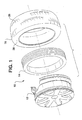
- FIG. 1 An example of a run-flat tire assembly 10 is shown in FIG. 1.
- the tire assembly 10 is shown as being made of three basic components. First, an alloy or steel integral wheel rim 12 is provided onto which a support member 14 is placed. The support member 14 shown in FIG. 1 is a ring. Next, a rubber tire 16 is placed onto the rim 12 and completely surrounds the support member 14. The tire assembly 10 is shown in an assembled state in FIG. 2. The tire 16 is vertically anchored to the rim 12 as described in U.S. Patent Number 5,634,993.
- FIG. 3 shows a partial cross sectional view of a tire assembly 10 in accordance with one exemplary embodiment of a run-flat tire assembly.
- the support member 14 is similar to that disclosed in the '279 patent mentioned above, and is located on a cylindrical section 18 of the rim 12.
- tire 16 is provided with tire tread 26 on its outer surface.
- Two side walls 28 extend from the tire tread 26 portion of tire 16.
- the side walls 28 are substantially vertical in orientation once seated onto the rim 12.
- a first bead 30 is present at the end of one of the side walls 28, and a second bead 32 is present at the end of the other side wall 28.
- the beads 30, 32 keep the tire 16 attached to the rim 12 and also create an air seal to maintain air pressure in the space 34 formed between the tire 16 and rim 12.
- Rim 12 has a first bead seat 36 and a second bead seat 38 formed therein for seating the first and second beads 30 and 32 respectively.
- the first bead seat 36 is formed by a pair of humps 40 and 42.
- the second bead seat 38 is formed by a pair of humps 44 and 46.
- An air seal is formed between the first bead 30 and the first bead seat 36.
- an air seal is also formed between the second bead 32 and the second bead seat 38.
- FIGS. 4 through 8 illustrate an exemplary embodiment of a mold element 110 for molding bead 32 of a tire 16.
- Mold element 110 is depicted in the open or collapsed position in FIG. 5 and FIG 7. In such position, tire 16 may be removed from mold element 110.
- mold element 110 is depicted in the closed or expanded position in FIG. 6 and FIG. 8. In this position, mold element 110 is contact with tire 17 and operates to form bead 32 into the desired shape.
- FIG. 7 and FIG. 8 depict mold element 110 being used in conjunction with a curing press 166.
- Curing is a step in the manufacturing process during which tread detail, lettering, and other features may be added while the tire 16 is subjected to heat and pressure.
- the shape of bead 30 or bead 32 is also formed during this step.
- Press 166 includes two halves 168 and 170 that are used to press or sandwich tire 16 during the curing step. As depicted, the press 166 is open in FIG. 7 and in FIG. 8.
- the internal walls of halves 168 and 170 include, for example, tread detail 172 for impression upon tire 16.
- mold element 110 includes a loading plate 112 that may be attached to the bottom of a curing press 166 or other tire manufacturing apparatus as desired.
- the internal surface 114 of loading plate 112 defines a cavity 116.
- Loading plate 112 also has a central axis AA, designated with dashed lines in FIGS. 5 and 6.
- Bolts or pins may be inserted through apertures 118 and 120 for orienting and attaching loading plate 112 to the curing press 166 or other equipment.
- Base 122 is received within cavity 116 of loading plate 112 and has a first surface 126 and a second surface 124. Base 122 is movable in both directions along central axis AA.
- a plurality of springs 128 provide mechanical communication between first surface 126 of base 122 and loading plate 112. More specifically, loading plate 112 supports base 122 through the plurality of springs 128. Pins 130 operate to orient and guide the plurality of springs 128. As will be described below, the plurality of springs 128 are compressed when base 122 is moved towards loading plate 112 along axis AA and are therefore released as base 122 is moved away from loading plate 112.
- radial sectors 132 and floating sectors 134 Attached to the second surface 124 of base 122 in alternating positions are radial sectors 132 and floating sectors 134.
- ctor describes the geometrical shape of two radii and the arc of at least one circle. The center of such circle defines an axial direction congruent or parallel with axis AA, and a radial direction that is perpendicular to the axial direction.
- radial sectors 132 and floating sectors 134 are depicted as sections that together form a circular or annular disk having an aperture 136 (FIG. 4) positioned at its center.
- the present invention may contain any number of sectors 132 and 134, and is not limited to only the use of six radial sectors 132 and floating sectors 134 nor to the use of sectors having the same shape as illustrated in FIGS. 1-6. Furthermore, sections having shapes other than as depicted for radial sectors 132 and floating sectors 134 may be used to form the overall circular or annular shape.
- each radial sector 132 is configured for reciprocal movement in a radial direction. More specifically, each radial sector 132 is configured for movement within a plane and direction that is perpendicular to central axis AA (shown in FIGS. 5-6).
- Pin 138 connects radial sector 132 to base 122 through link 140.
- Base 122 defines a chamber 142 housing a compressive spring 144 that is in mechanical communication with compressive link 140 through pin 146.
- pin 146 and a portion of link 140 are constrained to move within chamber 142 and compressive spring 144 is compressed.
- spring 144 is released.
- Each floating sector 134 is configured for reciprocal simultaneous radial and axial movement. More specifically, each floating sector 134 moves in a direction that is diagonal to axis AA. This direction is indicated by axis BB (FIGS. 5-6).
- Guide pin 152 connects floating sector 134 to base 122. When mold element 110 is in the expanded position shown in FIG. 6, guide pin 152 is contained within recesses 154 and 156 located in floating sector 134 and base 122 respectively. Guide pin 152 also operates in conjunction with compressive spring 158. Accordingly, as floating sector 134 is moved along axis BB, compressive spring 158 is compressed when floating sector 134 is moved towards base 122 and released when floating sector 134 moves away from base 122.
- axis BB forms an angle of 30 degrees as measured in a counter-clockwise direction from central axis AA. It should be understood, however, that the present invention is not limited to an angle of 30 degrees for axis BB, and other angles may be used as will be understood by one of ordinary skill in the art using the teachings disclosed herein.
- Radial sectors 132 each have a drive surface 147 located along an inner radius, while floating sectors 134 each have a drive surface 149 located along an inner radius. These drive surfaces 147 and 149 are beveled and oriented for mating contact with a contacting surface 160 (FIG. 5) on actuator 162. More specifically, actuator 162 has a frustoconically-shaped contacting surface 160 for contacting and driving frustoconically-shaped surfaces 147 and 149. Preferably, contacting surface 160 is at an angle of 30 degrees as measured in a direction clockwise from central axis AA. However, it should be appreciated that other angles may be used for contacting surface 160 as will be understood by one of skill in the art using the teachings disclosed herein.
- a top plate 164 is attached to actuator 162. Accordingly, as top plate 164 and actuator 162 are moved along axis AA towards base 122, contacting surface 160 contacts drive surfaces 147 and 149. Consequently, radial sectors 132 are driven in a radial direction outward from axis AA while floating sectors 134 are driven towards base 122 in a direction along axis BB.
- floating sectors 134 and radial sectors 132 also engage and bear upon each other along angled surfaces 135 and 137. Surfaces 135 and 137 are preferably angled at 45 degrees; however, other angles may be used as will be understood by one of skill in the art using the teachings disclosed herein.
- the base 122 moves downward into the cavity 116 in the loading plate 112, which allows the continuous surface formed by the engaged sectors to come into contact with the tire bead with an axial movement.
- Actuator 162 and top plate 164 may be powered by operation of a hydraulic piston or shaft 174 extending through aperture 136.
- a hydraulic piston or shaft 174 extending through aperture 136.
- other means of powering actuator 162 and top plate 164 may be envisioned using the teachings disclosed herein.
- Radial sectors 132 each have a tire bead molding surface 148 located along an outer radius.
- floating sectors 134 each have a tire bead molding surface 150 located along an outer radius.
- the tire bead molding surface 148 of each radial sector 132 and the tire bead molding surface 150 of each floating sector 134 collectively form a continuous surface that presses against second bead 32. More specifically, the series of mating surfaces provided by surfaces 148, 150, 135, and 137 allow for the application of a uniform, continuous surface to second bead 32.
- mold element 110 is used to assist in shaping second bead 32 as desired while also molding a smooth surface along second bead 32 for creating a tight air seal. Mold element 110 also performs the secondary function of helping to secure the position of tire 16 during the curing step.
- the present invention may be configured for use with first bead 30 and is not limited to using second bead 32 as will be understood by one of skill in the art using the teachings disclosed herein. More specifically, the orientation of tire 16 as shown in FIG. 5 and FIG. 6 is by way of example only.
- a tire 16 is placed into, for example, a curing press 166 and second bead 32 is placed over mold element 110.
- Top plate 164 and actuator 162 are then moved along axis AA towards loading plate 112 by operation of shaft 174.
- Contacting surface 160 then urges radial sectors 132 and floating sectors 134 from a collapsed or open position shown in FIGS. 5 and 7 to a closed or expanded position as shown in FIGS. 6 and 8.
- contacting surface 160 contacts and drives surfaces 147 so as to cause radial sectors 132 to move radially outward and floating sectors 134 to move along diagonal axis BB.
- Compressive springs 144 and 158 are compressed.
- the plurality of springs 128 are also compressed as base 122 is urged towards loading plate 112.
- tire seating surfaces 148 and 150 contact and apply pressure to second bead 32 and thereby provide a uniform pressure and a continuous, sealed molding surface against second bead 32.
- Radial sectors 132 and floating sectors 134 are now in a secure or clamped position as tire 16 is now fixed in place by mold element 110. Accordingly, mold element 110 can be used to mold second bead 32 into the shape desired and to provide a smooth surface for sealing air within the tire during operation.
- top plate 164 and actuator 162 are moved along axis AA away from loading plate 112.
- compressive springs 144 cause radial sectors 132 to move radially inward towards axis AA.
- Compressive springs 158 cause floating sectors 134 to move diagonally upwards along axis BB.
- Base 122 is also driven away from loading plate 112 by operation of the plurality of springs 128.
- tire seating surfaces 148 and 150 release pressure from second bead 32 allowing tire 16 to be removed.
- Radial sectors 132 and floating sectors 134 are now in a release position as tire 16 can now be removed from mold element 110.
Landscapes
- Engineering & Computer Science (AREA)
- Mechanical Engineering (AREA)
- Moulds For Moulding Plastics Or The Like (AREA)
- Heating, Cooling, Or Curing Plastics Or The Like In General (AREA)
- Tires In General (AREA)
Abstract
Description
Claims (11)
- Mold for a tire, comprising:a loading plate defining a cavity and having a central axis;a base received within said cavity, said base having an engagement surface, and being movable along said central axis;an actuator movable along said central axis between a spaced position and an engaged position relative to said base;at least one sliding section movably attached to said engagement surface, said sliding section movable in a direction perpendicular to said central axis between an engaged position and a retracted position, and having a molding surface for a tire bead;at least one floating section movably attached to said engagement surface and movable on a diagonal axis relative to said central axis between an engaged position and a retracted position, and having a molding surface for a tire bead, said at least one sliding section and at least one floating section being mutually alternately disposed; and,means for moving said actuator from the spaced position to the engaged position for driving said at least one sliding section and said at least one floating section to the respective engaged positions so that the respective molding surfaces join to form a continuous molding surface for a tire bead.
- Mold according to claim 1, wherein said actuator has a frustoconically shaped driving surface and said at least one sliding section and said at least one floating section each have frustoconically shaped follower surfaces for being driven by the actuator.
- Mold according to any preceding claim, wherein said at least one floating section is biased to the retracted position spaced along the central axis from said base and radially inward toward the central axis.
- Mold according to any preceding claim, wherein said at least one sliding section is biased to the retracted position radially inward toward the central axis.
- Mold according to claim 2, further comprising a plurality of spring loaded members, mechanically connected between said floating section and said base, and configured for biasing said follower surfaces of said floating section against said driving surface of said actuator.
- Mold according any preceding claim, wherein said at least one floating section has at least one joining surface and said at least one sliding section has at least one joining surface which mutually bear on one another when the respective sections are in the engaged position.
- Mold according to claim 5, wherein said floating section and said radial section matingly engage each other along adjoining angled surfaces.
- Mold according to any preceding claim, wherein the base is biased to a raised position in said cavity in which the at least one sliding section is positioned axially spaced from a bead molding position, and wherein movement of the actuator moves the base to a recessed position in which the at least one sliding section is in the bead molding position.
- Mold according to any preceding claim, wherein said diagonal axis is at an angle of about 30 degrees as measured in the counter-clockwise direction from said central axis.
- Process for molding a tire characterized by using a mold according to any preceding claim.
- Tire characterized in that it is obtained by the process of claim 10.
Applications Claiming Priority (2)
| Application Number | Priority Date | Filing Date | Title |
|---|---|---|---|
| US10/123,795 US6726460B2 (en) | 2002-04-16 | 2002-04-16 | Collapsible mechanism for molding a tire bead |
| US123795 | 2002-04-16 |
Publications (3)
| Publication Number | Publication Date |
|---|---|
| EP1354682A2 true EP1354682A2 (en) | 2003-10-22 |
| EP1354682A3 EP1354682A3 (en) | 2005-05-18 |
| EP1354682B1 EP1354682B1 (en) | 2007-04-04 |
Family
ID=28674674
Family Applications (1)
| Application Number | Title | Priority Date | Filing Date |
|---|---|---|---|
| EP03008323A Expired - Lifetime EP1354682B1 (en) | 2002-04-16 | 2003-04-10 | Collapsible mechanism for molding a tire bead |
Country Status (11)
| Country | Link |
|---|---|
| US (1) | US6726460B2 (en) |
| EP (1) | EP1354682B1 (en) |
| JP (1) | JP2003311744A (en) |
| KR (1) | KR20030082424A (en) |
| CN (1) | CN1451525A (en) |
| AT (1) | ATE358565T1 (en) |
| AU (1) | AU2003203731A1 (en) |
| BR (1) | BR0300987A (en) |
| CA (1) | CA2425786A1 (en) |
| DE (1) | DE60312914T2 (en) |
| MX (1) | MXPA03003293A (en) |
Families Citing this family (6)
| Publication number | Priority date | Publication date | Assignee | Title |
|---|---|---|---|---|
| US7268165B2 (en) * | 2004-08-20 | 2007-09-11 | Steris Inc. | Enhanced activity alcohol-based antimicrobial compositions |
| CN102363365B (en) * | 2005-12-28 | 2014-06-11 | 倍耐力轮胎股份公司 | Method and apparatus for manufacturing pneumatic tyre |
| JP5285520B2 (en) * | 2009-07-02 | 2013-09-11 | 住友ゴム工業株式会社 | Run-flat tire assembly and support ring used therefor |
| MX2013015365A (en) * | 2011-06-30 | 2014-02-11 | Michelin & Cie | Methods and apparatus for installing a tread ring upon a tire carcass. |
| CN104943214A (en) * | 2014-03-25 | 2015-09-30 | 青岛软控机电工程有限公司 | Tire bead presetting device |
| CN109016587B (en) * | 2018-10-26 | 2024-11-22 | 山东豪迈机械科技股份有限公司 | Retractable device and tire mold |
Family Cites Families (40)
| Publication number | Priority date | Publication date | Assignee | Title |
|---|---|---|---|---|
| US1704440A (en) | 1924-10-31 | 1929-03-05 | Fisk Rubber Co | Collapsible holding device |
| US2904832A (en) | 1955-08-24 | 1959-09-22 | Cleveland Trust Co | Expandable bead ring for vulcanizing presses |
| US2939175A (en) | 1956-02-13 | 1960-06-07 | Cleveland Trust Co | Two-way expandable inner bead forming ring for vulcanizing presses |
| US3153263A (en) * | 1957-11-07 | 1964-10-20 | Nat Rubber Machinery Co | Tire curing press |
| GB1559772A (en) | 1975-10-02 | 1980-01-23 | Dunlop Ltd | Pneumatic tyre manufacture |
| US4236883A (en) * | 1979-07-05 | 1980-12-02 | Nrm Corporation | Tire press |
| JPS59167243A (en) * | 1983-03-14 | 1984-09-20 | Kazumasa Sarumaru | Tire encloser in tire vulcanizer |
| DE3442303A1 (en) | 1984-11-20 | 1986-05-22 | Continental Gummi-Werke Ag, 3000 Hannover | VOLCANIZING METHOD AND DEVICE FOR AIR TIRES |
| GB8826013D0 (en) | 1988-11-07 | 1988-12-14 | Kobe Steel Ltd | Bladderless tyre moulding apparatus & method of operating same |
| US5252652A (en) * | 1989-05-11 | 1993-10-12 | Bridgestone Corporation | Solid golf ball |
| US5605968A (en) * | 1993-03-17 | 1997-02-25 | Bridgestone Sports, Co., Ltd. | Golf ball |
| JPH0898901A (en) * | 1994-09-30 | 1996-04-16 | Sumitomo Rubber Ind Ltd | Solid golf ball and method of manufacturing the same |
| KR960037077A (en) * | 1995-04-05 | 1996-11-19 | 사이또 나오또 | Solid golf ball in three sides |
| JPH0928830A (en) * | 1995-07-13 | 1997-02-04 | Sumitomo Rubber Ind Ltd | Solid golf ball |
| AU703884B2 (en) * | 1995-08-25 | 1999-04-01 | Sumitomo Rubber Industries, Ltd. | Solid golf ball |
| US5994472A (en) * | 1995-08-25 | 1999-11-30 | Bridgestone Sports Co., Ltd. | Ionomer covered golf ball |
| JPH0960781A (en) * | 1995-08-28 | 1997-03-04 | Maruyasu Kogyo Kk | Pipe joint |
| US5779563A (en) * | 1996-02-09 | 1998-07-14 | Bridgestone Sports Co., Ltd. | Multi-piece solid golf ball |
| JP3304781B2 (en) * | 1996-09-06 | 2002-07-22 | ブリヂストンスポーツ株式会社 | Golf ball |
| JP3428330B2 (en) * | 1996-11-05 | 2003-07-22 | ブリヂストンスポーツ株式会社 | Golf ball |
| US5877264A (en) * | 1996-11-25 | 1999-03-02 | E. I. Du Pont De Nemours And Company | Fast-curing perfluoroelastomer composition |
| AU724254B2 (en) * | 1996-12-05 | 2000-09-14 | Sumitomo Rubber Industries, Ltd. | Solid golf ball |
| JPH10314340A (en) * | 1997-05-16 | 1998-12-02 | Sumitomo Rubber Ind Ltd | Solid golf ball |
| JP3985105B2 (en) * | 1997-05-23 | 2007-10-03 | ブリヂストンスポーツ株式会社 | Method for producing solid golf ball |
| JP3912446B2 (en) * | 1997-08-08 | 2007-05-09 | ブリヂストンスポーツ株式会社 | Multi-piece solid golf ball |
| US6248028B1 (en) * | 1997-08-08 | 2001-06-19 | Bridgestone Sports Co., Ltd. | Multi-piece solid golf ball |
| US6267692B1 (en) * | 1997-08-08 | 2001-07-31 | Bridgestone Sports Co., Ltd. | Multi-piece solid golf ball |
| US6267694B1 (en) * | 1997-08-08 | 2001-07-31 | Bridgestone Sports Co., Ltd. | Multi-piece solid golf ball |
| GB9905914D0 (en) * | 1998-03-16 | 1999-05-05 | Bridgestone Sports Co Ltd | Multi-piece solid golf ball |
| JP3221390B2 (en) * | 1998-03-16 | 2001-10-22 | ブリヂストンスポーツ株式会社 | Multi-piece solid golf ball |
| JP3178410B2 (en) * | 1998-03-16 | 2001-06-18 | ブリヂストンスポーツ株式会社 | Multi-piece solid golf ball |
| JP3221391B2 (en) * | 1998-03-16 | 2001-10-22 | ブリヂストンスポーツ株式会社 | Multilayer solid golf ball |
| US6238193B1 (en) | 1998-07-23 | 2001-05-29 | Michelin Recherche Et Technique S.A. | Mold for tire and vulcanizing press fitted to receive mold |
| US6244978B1 (en) * | 1998-09-03 | 2001-06-12 | Bridgestone Sports Co., Ltd. | Multi-piece solid golf ball |
| JP3428454B2 (en) * | 1998-09-03 | 2003-07-22 | ブリヂストンスポーツ株式会社 | Multi-piece solid golf ball |
| US6299551B1 (en) * | 1998-09-03 | 2001-10-09 | Bridgestone Sports Co., Ltd. | Multi-piece solid golf ball |
| JP2000070414A (en) * | 1998-09-03 | 2000-03-07 | Bridgestone Sports Co Ltd | Multi-piece solid golf ball |
| JP4069338B2 (en) * | 1998-09-09 | 2008-04-02 | ブリヂストンスポーツ株式会社 | Golf ball |
| US6287218B1 (en) * | 1998-10-12 | 2001-09-11 | Sumitomo Rubber Industries, Ltd. | Solid golf ball |
| JP2000176049A (en) * | 1998-12-18 | 2000-06-27 | Sumitomo Rubber Ind Ltd | Solid golf ball |
-
2002
- 2002-04-16 US US10/123,795 patent/US6726460B2/en not_active Expired - Fee Related
-
2003
- 2003-04-10 DE DE60312914T patent/DE60312914T2/en not_active Expired - Fee Related
- 2003-04-10 EP EP03008323A patent/EP1354682B1/en not_active Expired - Lifetime
- 2003-04-10 AT AT03008323T patent/ATE358565T1/en not_active IP Right Cessation
- 2003-04-14 MX MXPA03003293A patent/MXPA03003293A/en active IP Right Grant
- 2003-04-14 BR BR0300987-4A patent/BR0300987A/en not_active IP Right Cessation
- 2003-04-15 AU AU2003203731A patent/AU2003203731A1/en not_active Abandoned
- 2003-04-15 JP JP2003110246A patent/JP2003311744A/en active Pending
- 2003-04-15 CA CA002425786A patent/CA2425786A1/en not_active Abandoned
- 2003-04-15 KR KR10-2003-0023587A patent/KR20030082424A/en not_active Withdrawn
- 2003-04-16 CN CN03122208A patent/CN1451525A/en active Pending
Also Published As
| Publication number | Publication date |
|---|---|
| JP2003311744A (en) | 2003-11-05 |
| EP1354682A3 (en) | 2005-05-18 |
| ATE358565T1 (en) | 2007-04-15 |
| US6726460B2 (en) | 2004-04-27 |
| MXPA03003293A (en) | 2005-02-14 |
| CA2425786A1 (en) | 2003-10-16 |
| DE60312914D1 (en) | 2007-05-16 |
| DE60312914T2 (en) | 2007-12-20 |
| CN1451525A (en) | 2003-10-29 |
| KR20030082424A (en) | 2003-10-22 |
| BR0300987A (en) | 2004-09-08 |
| EP1354682B1 (en) | 2007-04-04 |
| AU2003203731A1 (en) | 2003-10-30 |
| US20030194458A1 (en) | 2003-10-16 |
Similar Documents
| Publication | Publication Date | Title |
|---|---|---|
| US5853526A (en) | Tire assembling and vulcanization | |
| EP0015224B1 (en) | Building and shaping a tire | |
| JP4422522B2 (en) | Self-locking tire mold | |
| US20170305089A1 (en) | Method of controlling a phase of moulding an annular fixing structure and a tyre including an annular fixing structure | |
| US7318714B2 (en) | Core for manufacturing pneumatic tires | |
| EP1354682B1 (en) | Collapsible mechanism for molding a tire bead | |
| WO2022269943A1 (en) | Tire molding mold and tire manufacturing method | |
| US5433814A (en) | Green tire building apparatus | |
| EP0509095B1 (en) | Green tire building apparatus | |
| CN101541519A (en) | Process and apparatus for manufacturing tyres | |
| EP1932645A1 (en) | Tire vulcanizer | |
| WO2023079782A1 (en) | Tire molding mold and tire manufacturing method | |
| US12544999B2 (en) | Mold for forming a tire and tire production method | |
| JP2001315128A (en) | Tire vulcanizer and tire vulcanizing method | |
| WO2022269941A1 (en) | Tire molding mold and tire manufacturing method | |
| EP4438282A1 (en) | Segmented curing ring and tire mold for npt elastomer bands and method for curing a green elastomer band | |
| JP7559268B2 (en) | CURING MOLD ASSEMBLY FOR NON-PNEUMATIC TIRE AND METHOD FOR MANUFACTURING SAME - Patent application | |
| CN118176106A (en) | Method and actuating device for applying an insert to a vulcanization mold and process for producing wheel tires using the vulcanization mold | |
| JP4903952B2 (en) | Tire vulcanization mold | |
| CN111051048B (en) | Equipment for building tires for vehicle wheels | |
| GB2140751A (en) | Apparatus for the manufacture of tyres | |
| JPH0651370B2 (en) | Raw tire building equipment |
Legal Events
| Date | Code | Title | Description |
|---|---|---|---|
| PUAI | Public reference made under article 153(3) epc to a published international application that has entered the european phase |
Free format text: ORIGINAL CODE: 0009012 |
|
| AK | Designated contracting states |
Kind code of ref document: A2 Designated state(s): AT BE BG CH CY CZ DE DK EE ES FI FR GB GR HU IE IT LI LU MC NL PT RO SE SI SK TR |
|
| AX | Request for extension of the european patent |
Extension state: AL LT LV MK |
|
| PUAL | Search report despatched |
Free format text: ORIGINAL CODE: 0009013 |
|
| AK | Designated contracting states |
Kind code of ref document: A3 Designated state(s): AT BE BG CH CY CZ DE DK EE ES FI FR GB GR HU IE IT LI LU MC NL PT RO SE SI SK TR |
|
| AX | Request for extension of the european patent |
Extension state: AL LT LV MK |
|
| RIC1 | Information provided on ipc code assigned before grant |
Ipc: 7B 29L 30:00 Z Ipc: 7B 29D 30/06 B Ipc: 7B 29C 33/48 A |
|
| 17P | Request for examination filed |
Effective date: 20051118 |
|
| AKX | Designation fees paid |
Designated state(s): AT BE BG CH CY CZ DE DK EE ES FI FR GB GR HU IE IT LI LU MC NL PT RO SE SI SK TR |
|
| GRAP | Despatch of communication of intention to grant a patent |
Free format text: ORIGINAL CODE: EPIDOSNIGR1 |
|
| RIC1 | Information provided on ipc code assigned before grant |
Ipc: B29D 30/06 20060101ALI20060921BHEP Ipc: B29C 33/48 20060101AFI20060921BHEP |
|
| GRAS | Grant fee paid |
Free format text: ORIGINAL CODE: EPIDOSNIGR3 |
|
| GRAA | (expected) grant |
Free format text: ORIGINAL CODE: 0009210 |
|
| AK | Designated contracting states |
Kind code of ref document: B1 Designated state(s): AT BE BG CH CY CZ DE DK EE ES FI FR GB GR HU IE IT LI LU MC NL PT RO SE SI SK TR |
|
| PG25 | Lapsed in a contracting state [announced via postgrant information from national office to epo] |
Ref country code: CH Free format text: LAPSE BECAUSE OF FAILURE TO SUBMIT A TRANSLATION OF THE DESCRIPTION OR TO PAY THE FEE WITHIN THE PRESCRIBED TIME-LIMIT Effective date: 20070404 Ref country code: LI Free format text: LAPSE BECAUSE OF FAILURE TO SUBMIT A TRANSLATION OF THE DESCRIPTION OR TO PAY THE FEE WITHIN THE PRESCRIBED TIME-LIMIT Effective date: 20070404 Ref country code: SI Free format text: LAPSE BECAUSE OF FAILURE TO SUBMIT A TRANSLATION OF THE DESCRIPTION OR TO PAY THE FEE WITHIN THE PRESCRIBED TIME-LIMIT Effective date: 20070404 Ref country code: FI Free format text: LAPSE BECAUSE OF FAILURE TO SUBMIT A TRANSLATION OF THE DESCRIPTION OR TO PAY THE FEE WITHIN THE PRESCRIBED TIME-LIMIT Effective date: 20070404 |
|
| REG | Reference to a national code |
Ref country code: GB Ref legal event code: FG4D |
|
| REG | Reference to a national code |
Ref country code: CH Ref legal event code: EP |
|
| REF | Corresponds to: |
Ref document number: 60312914 Country of ref document: DE Date of ref document: 20070516 Kind code of ref document: P |
|
| REG | Reference to a national code |
Ref country code: IE Ref legal event code: FG4D |
|
| PGFP | Annual fee paid to national office [announced via postgrant information from national office to epo] |
Ref country code: ES Payment date: 20070521 Year of fee payment: 5 |
|
| PG25 | Lapsed in a contracting state [announced via postgrant information from national office to epo] |
Ref country code: SE Free format text: LAPSE BECAUSE OF FAILURE TO SUBMIT A TRANSLATION OF THE DESCRIPTION OR TO PAY THE FEE WITHIN THE PRESCRIBED TIME-LIMIT Effective date: 20070704 |
|
| PG25 | Lapsed in a contracting state [announced via postgrant information from national office to epo] |
Ref country code: ES Free format text: LAPSE BECAUSE OF FAILURE TO SUBMIT A TRANSLATION OF THE DESCRIPTION OR TO PAY THE FEE WITHIN THE PRESCRIBED TIME-LIMIT Effective date: 20070715 |
|
| ET | Fr: translation filed | ||
| PG25 | Lapsed in a contracting state [announced via postgrant information from national office to epo] |
Ref country code: PT Free format text: LAPSE BECAUSE OF FAILURE TO SUBMIT A TRANSLATION OF THE DESCRIPTION OR TO PAY THE FEE WITHIN THE PRESCRIBED TIME-LIMIT Effective date: 20070904 |
|
| NLV1 | Nl: lapsed or annulled due to failure to fulfill the requirements of art. 29p and 29m of the patents act | ||
| REG | Reference to a national code |
Ref country code: CH Ref legal event code: PL |
|
| PG25 | Lapsed in a contracting state [announced via postgrant information from national office to epo] |
Ref country code: AT Free format text: LAPSE BECAUSE OF FAILURE TO SUBMIT A TRANSLATION OF THE DESCRIPTION OR TO PAY THE FEE WITHIN THE PRESCRIBED TIME-LIMIT Effective date: 20070404 |
|
| PGFP | Annual fee paid to national office [announced via postgrant information from national office to epo] |
Ref country code: GB Payment date: 20070501 Year of fee payment: 5 |
|
| PG25 | Lapsed in a contracting state [announced via postgrant information from national office to epo] |
Ref country code: BE Free format text: LAPSE BECAUSE OF FAILURE TO SUBMIT A TRANSLATION OF THE DESCRIPTION OR TO PAY THE FEE WITHIN THE PRESCRIBED TIME-LIMIT Effective date: 20070404 |
|
| PG25 | Lapsed in a contracting state [announced via postgrant information from national office to epo] |
Ref country code: BG Free format text: LAPSE BECAUSE OF FAILURE TO SUBMIT A TRANSLATION OF THE DESCRIPTION OR TO PAY THE FEE WITHIN THE PRESCRIBED TIME-LIMIT Effective date: 20070704 Ref country code: NL Free format text: LAPSE BECAUSE OF FAILURE TO SUBMIT A TRANSLATION OF THE DESCRIPTION OR TO PAY THE FEE WITHIN THE PRESCRIBED TIME-LIMIT Effective date: 20070404 Ref country code: DK Free format text: LAPSE BECAUSE OF FAILURE TO SUBMIT A TRANSLATION OF THE DESCRIPTION OR TO PAY THE FEE WITHIN THE PRESCRIBED TIME-LIMIT Effective date: 20070404 Ref country code: CZ Free format text: LAPSE BECAUSE OF FAILURE TO SUBMIT A TRANSLATION OF THE DESCRIPTION OR TO PAY THE FEE WITHIN THE PRESCRIBED TIME-LIMIT Effective date: 20070404 |
|
| PLBE | No opposition filed within time limit |
Free format text: ORIGINAL CODE: 0009261 |
|
| STAA | Information on the status of an ep patent application or granted ep patent |
Free format text: STATUS: NO OPPOSITION FILED WITHIN TIME LIMIT |
|
| PG25 | Lapsed in a contracting state [announced via postgrant information from national office to epo] |
Ref country code: SK Free format text: LAPSE BECAUSE OF FAILURE TO SUBMIT A TRANSLATION OF THE DESCRIPTION OR TO PAY THE FEE WITHIN THE PRESCRIBED TIME-LIMIT Effective date: 20070404 |
|
| 26N | No opposition filed |
Effective date: 20080107 |
|
| PG25 | Lapsed in a contracting state [announced via postgrant information from national office to epo] |
Ref country code: GR Free format text: LAPSE BECAUSE OF FAILURE TO SUBMIT A TRANSLATION OF THE DESCRIPTION OR TO PAY THE FEE WITHIN THE PRESCRIBED TIME-LIMIT Effective date: 20070705 |
|
| PG25 | Lapsed in a contracting state [announced via postgrant information from national office to epo] |
Ref country code: IE Free format text: LAPSE BECAUSE OF NON-PAYMENT OF DUE FEES Effective date: 20070410 Ref country code: RO Free format text: LAPSE BECAUSE OF FAILURE TO SUBMIT A TRANSLATION OF THE DESCRIPTION OR TO PAY THE FEE WITHIN THE PRESCRIBED TIME-LIMIT Effective date: 20070404 |
|
| PGFP | Annual fee paid to national office [announced via postgrant information from national office to epo] |
Ref country code: DE Payment date: 20080417 Year of fee payment: 6 Ref country code: FR Payment date: 20080312 Year of fee payment: 6 |
|
| PGFP | Annual fee paid to national office [announced via postgrant information from national office to epo] |
Ref country code: IT Payment date: 20080426 Year of fee payment: 6 |
|
| GBPC | Gb: european patent ceased through non-payment of renewal fee |
Effective date: 20080410 |
|
| PG25 | Lapsed in a contracting state [announced via postgrant information from national office to epo] |
Ref country code: EE Free format text: LAPSE BECAUSE OF FAILURE TO SUBMIT A TRANSLATION OF THE DESCRIPTION OR TO PAY THE FEE WITHIN THE PRESCRIBED TIME-LIMIT Effective date: 20070404 |
|
| PG25 | Lapsed in a contracting state [announced via postgrant information from national office to epo] |
Ref country code: MC Free format text: LAPSE BECAUSE OF NON-PAYMENT OF DUE FEES Effective date: 20070430 |
|
| PG25 | Lapsed in a contracting state [announced via postgrant information from national office to epo] |
Ref country code: GB Free format text: LAPSE BECAUSE OF NON-PAYMENT OF DUE FEES Effective date: 20080410 |
|
| PG25 | Lapsed in a contracting state [announced via postgrant information from national office to epo] |
Ref country code: CY Free format text: LAPSE BECAUSE OF FAILURE TO SUBMIT A TRANSLATION OF THE DESCRIPTION OR TO PAY THE FEE WITHIN THE PRESCRIBED TIME-LIMIT Effective date: 20070404 |
|
| PG25 | Lapsed in a contracting state [announced via postgrant information from national office to epo] |
Ref country code: LU Free format text: LAPSE BECAUSE OF NON-PAYMENT OF DUE FEES Effective date: 20070410 |
|
| PG25 | Lapsed in a contracting state [announced via postgrant information from national office to epo] |
Ref country code: HU Free format text: LAPSE BECAUSE OF FAILURE TO SUBMIT A TRANSLATION OF THE DESCRIPTION OR TO PAY THE FEE WITHIN THE PRESCRIBED TIME-LIMIT Effective date: 20071005 Ref country code: TR Free format text: LAPSE BECAUSE OF FAILURE TO SUBMIT A TRANSLATION OF THE DESCRIPTION OR TO PAY THE FEE WITHIN THE PRESCRIBED TIME-LIMIT Effective date: 20070404 |
|
| REG | Reference to a national code |
Ref country code: FR Ref legal event code: ST Effective date: 20091231 |
|
| PG25 | Lapsed in a contracting state [announced via postgrant information from national office to epo] |
Ref country code: DE Free format text: LAPSE BECAUSE OF NON-PAYMENT OF DUE FEES Effective date: 20091103 |
|
| PG25 | Lapsed in a contracting state [announced via postgrant information from national office to epo] |
Ref country code: FR Free format text: LAPSE BECAUSE OF NON-PAYMENT OF DUE FEES Effective date: 20091222 |
|
| PG25 | Lapsed in a contracting state [announced via postgrant information from national office to epo] |
Ref country code: IT Free format text: LAPSE BECAUSE OF NON-PAYMENT OF DUE FEES Effective date: 20090410 |