EP1353852B1 - Can end for a container - Google Patents
Can end for a container Download PDFInfo
- Publication number
- EP1353852B1 EP1353852B1 EP01995390A EP01995390A EP1353852B1 EP 1353852 B1 EP1353852 B1 EP 1353852B1 EP 01995390 A EP01995390 A EP 01995390A EP 01995390 A EP01995390 A EP 01995390A EP 1353852 B1 EP1353852 B1 EP 1353852B1
- Authority
- EP
- European Patent Office
- Prior art keywords
- panel
- score
- end member
- deboss
- frangible
- Prior art date
- Legal status (The legal status is an assumption and is not a legal conclusion. Google has not performed a legal analysis and makes no representation as to the accuracy of the status listed.)
- Expired - Lifetime
Links
- 230000002093 peripheral effect Effects 0.000 claims description 24
- 230000002968 anti-fracture Effects 0.000 claims description 14
- 238000000034 method Methods 0.000 claims description 14
- 238000002407 reforming Methods 0.000 claims description 5
- 230000007704 transition Effects 0.000 claims description 3
- 238000013022 venting Methods 0.000 abstract description 6
- 229910052751 metal Inorganic materials 0.000 description 43
- 239000002184 metal Substances 0.000 description 43
- 239000011324 bead Substances 0.000 description 14
- 238000012360 testing method Methods 0.000 description 8
- 235000013361 beverage Nutrition 0.000 description 7
- 230000008569 process Effects 0.000 description 7
- 229910052782 aluminium Inorganic materials 0.000 description 5
- XAGFODPZIPBFFR-UHFFFAOYSA-N aluminium Chemical compound [Al] XAGFODPZIPBFFR-UHFFFAOYSA-N 0.000 description 5
- 235000013405 beer Nutrition 0.000 description 4
- 229910000831 Steel Inorganic materials 0.000 description 3
- 230000015572 biosynthetic process Effects 0.000 description 3
- 238000006243 chemical reaction Methods 0.000 description 3
- 230000007423 decrease Effects 0.000 description 3
- 239000000203 mixture Substances 0.000 description 3
- 230000002028 premature Effects 0.000 description 3
- 238000004826 seaming Methods 0.000 description 3
- 239000010959 steel Substances 0.000 description 3
- 230000009977 dual effect Effects 0.000 description 2
- 239000000463 material Substances 0.000 description 2
- 238000009928 pasteurization Methods 0.000 description 2
- 230000000717 retained effect Effects 0.000 description 2
- 230000002146 bilateral effect Effects 0.000 description 1
- 230000006835 compression Effects 0.000 description 1
- 238000007906 compression Methods 0.000 description 1
- 238000010276 construction Methods 0.000 description 1
- 230000003247 decreasing effect Effects 0.000 description 1
- 230000001419 dependent effect Effects 0.000 description 1
- 238000013461 design Methods 0.000 description 1
- 238000006073 displacement reaction Methods 0.000 description 1
- 238000011156 evaluation Methods 0.000 description 1
- 230000002349 favourable effect Effects 0.000 description 1
- 239000012634 fragment Substances 0.000 description 1
- 230000013011 mating Effects 0.000 description 1
- 230000000704 physical effect Effects 0.000 description 1
- 230000009467 reduction Effects 0.000 description 1
- 239000011435 rock Substances 0.000 description 1
- 238000000926 separation method Methods 0.000 description 1
- 238000005482 strain hardening Methods 0.000 description 1
Images


Classifications
-
- B—PERFORMING OPERATIONS; TRANSPORTING
- B65—CONVEYING; PACKING; STORING; HANDLING THIN OR FILAMENTARY MATERIAL
- B65D—CONTAINERS FOR STORAGE OR TRANSPORT OF ARTICLES OR MATERIALS, e.g. BAGS, BARRELS, BOTTLES, BOXES, CANS, CARTONS, CRATES, DRUMS, JARS, TANKS, HOPPERS, FORWARDING CONTAINERS; ACCESSORIES, CLOSURES, OR FITTINGS THEREFOR; PACKAGING ELEMENTS; PACKAGES
- B65D17/00—Rigid or semi-rigid containers specially constructed to be opened by cutting or piercing, or by tearing of frangible members or portions
- B65D17/06—Integral, or permanently secured, end or side closures
- B65D17/08—Closures secured by folding or rolling and pressing
-
- B—PERFORMING OPERATIONS; TRANSPORTING
- B65—CONVEYING; PACKING; STORING; HANDLING THIN OR FILAMENTARY MATERIAL
- B65D—CONTAINERS FOR STORAGE OR TRANSPORT OF ARTICLES OR MATERIALS, e.g. BAGS, BARRELS, BOTTLES, BOXES, CANS, CARTONS, CRATES, DRUMS, JARS, TANKS, HOPPERS, FORWARDING CONTAINERS; ACCESSORIES, CLOSURES, OR FITTINGS THEREFOR; PACKAGING ELEMENTS; PACKAGES
- B65D17/00—Rigid or semi-rigid containers specially constructed to be opened by cutting or piercing, or by tearing of frangible members or portions
- B65D17/28—Rigid or semi-rigid containers specially constructed to be opened by cutting or piercing, or by tearing of frangible members or portions at lines or points of weakness
- B65D17/401—Rigid or semi-rigid containers specially constructed to be opened by cutting or piercing, or by tearing of frangible members or portions at lines or points of weakness characterised by having the line of weakness provided in an end wall
- B65D17/4012—Rigid or semi-rigid containers specially constructed to be opened by cutting or piercing, or by tearing of frangible members or portions at lines or points of weakness characterised by having the line of weakness provided in an end wall for opening partially by means of a tearing tab
-
- B—PERFORMING OPERATIONS; TRANSPORTING
- B65—CONVEYING; PACKING; STORING; HANDLING THIN OR FILAMENTARY MATERIAL
- B65D—CONTAINERS FOR STORAGE OR TRANSPORT OF ARTICLES OR MATERIALS, e.g. BAGS, BARRELS, BOTTLES, BOXES, CANS, CARTONS, CRATES, DRUMS, JARS, TANKS, HOPPERS, FORWARDING CONTAINERS; ACCESSORIES, CLOSURES, OR FITTINGS THEREFOR; PACKAGING ELEMENTS; PACKAGES
- B65D7/00—Containers having bodies formed by interconnecting or uniting two or more rigid, or substantially rigid, components made wholly or mainly of metal
- B65D7/12—Containers having bodies formed by interconnecting or uniting two or more rigid, or substantially rigid, components made wholly or mainly of metal characterised by wall construction or by connections between walls
- B65D7/34—Containers having bodies formed by interconnecting or uniting two or more rigid, or substantially rigid, components made wholly or mainly of metal characterised by wall construction or by connections between walls with permanent connections between walls
- B65D7/36—Containers having bodies formed by interconnecting or uniting two or more rigid, or substantially rigid, components made wholly or mainly of metal characterised by wall construction or by connections between walls with permanent connections between walls formed by rolling, or by rolling and pressing
-
- B—PERFORMING OPERATIONS; TRANSPORTING
- B65—CONVEYING; PACKING; STORING; HANDLING THIN OR FILAMENTARY MATERIAL
- B65D—CONTAINERS FOR STORAGE OR TRANSPORT OF ARTICLES OR MATERIALS, e.g. BAGS, BARRELS, BOTTLES, BOXES, CANS, CARTONS, CRATES, DRUMS, JARS, TANKS, HOPPERS, FORWARDING CONTAINERS; ACCESSORIES, CLOSURES, OR FITTINGS THEREFOR; PACKAGING ELEMENTS; PACKAGES
- B65D2517/00—Containers specially constructed to be opened by cutting, piercing or tearing of wall portions, e.g. preserving cans or tins
- B65D2517/0001—Details
- B65D2517/001—Action for opening container
- B65D2517/0014—Action for opening container pivot tab and push-down tear panel
-
- B—PERFORMING OPERATIONS; TRANSPORTING
- B65—CONVEYING; PACKING; STORING; HANDLING THIN OR FILAMENTARY MATERIAL
- B65D—CONTAINERS FOR STORAGE OR TRANSPORT OF ARTICLES OR MATERIALS, e.g. BAGS, BARRELS, BOTTLES, BOXES, CANS, CARTONS, CRATES, DRUMS, JARS, TANKS, HOPPERS, FORWARDING CONTAINERS; ACCESSORIES, CLOSURES, OR FITTINGS THEREFOR; PACKAGING ELEMENTS; PACKAGES
- B65D2517/00—Containers specially constructed to be opened by cutting, piercing or tearing of wall portions, e.g. preserving cans or tins
- B65D2517/0001—Details
- B65D2517/0058—Other details of container end panel
- B65D2517/0059—General cross-sectional shape of container end panel
- B65D2517/0061—U-shaped
- B65D2517/0062—U-shaped and provided with an additional U-shaped peripheral channel
-
- B—PERFORMING OPERATIONS; TRANSPORTING
- B65—CONVEYING; PACKING; STORING; HANDLING THIN OR FILAMENTARY MATERIAL
- B65D—CONTAINERS FOR STORAGE OR TRANSPORT OF ARTICLES OR MATERIALS, e.g. BAGS, BARRELS, BOTTLES, BOXES, CANS, CARTONS, CRATES, DRUMS, JARS, TANKS, HOPPERS, FORWARDING CONTAINERS; ACCESSORIES, CLOSURES, OR FITTINGS THEREFOR; PACKAGING ELEMENTS; PACKAGES
- B65D2517/00—Containers specially constructed to be opened by cutting, piercing or tearing of wall portions, e.g. preserving cans or tins
- B65D2517/0001—Details
- B65D2517/0058—Other details of container end panel
- B65D2517/0068—Ribs or projections in container end panel
- B65D2517/007—Ribs or projections in container end panel located within tear-out/push-in panel
-
- B—PERFORMING OPERATIONS; TRANSPORTING
- B65—CONVEYING; PACKING; STORING; HANDLING THIN OR FILAMENTARY MATERIAL
- B65D—CONTAINERS FOR STORAGE OR TRANSPORT OF ARTICLES OR MATERIALS, e.g. BAGS, BARRELS, BOTTLES, BOXES, CANS, CARTONS, CRATES, DRUMS, JARS, TANKS, HOPPERS, FORWARDING CONTAINERS; ACCESSORIES, CLOSURES, OR FITTINGS THEREFOR; PACKAGING ELEMENTS; PACKAGES
- B65D2517/00—Containers specially constructed to be opened by cutting, piercing or tearing of wall portions, e.g. preserving cans or tins
- B65D2517/0001—Details
- B65D2517/0058—Other details of container end panel
- B65D2517/0074—Local recess in container end panel
- B65D2517/0076—Local recess in container end panel located beneath tab contact point
-
- Y—GENERAL TAGGING OF NEW TECHNOLOGICAL DEVELOPMENTS; GENERAL TAGGING OF CROSS-SECTIONAL TECHNOLOGIES SPANNING OVER SEVERAL SECTIONS OF THE IPC; TECHNICAL SUBJECTS COVERED BY FORMER USPC CROSS-REFERENCE ART COLLECTIONS [XRACs] AND DIGESTS
- Y10—TECHNICAL SUBJECTS COVERED BY FORMER USPC
- Y10S—TECHNICAL SUBJECTS COVERED BY FORMER USPC CROSS-REFERENCE ART COLLECTIONS [XRACs] AND DIGESTS
- Y10S220/00—Receptacles
- Y10S220/906—Beverage can, i.e. beer, soda
Definitions
- the present invention relates to end closures for two-piece beer and beverage metal containers having a non-detachable operating panel. More specifically, the present invention relates to improved forming techniques to produce a lightweight end closure.
- Common end closures for beer and beverage containers have a central panel that has a frangible panel (sometimes called a "tear panel,” “opening panel,” or “pour panel”) defined by a score formed on the outer surface, the "consumer side,” of the end closure.
- frangible panel sometimes called a "tear panel,” “opening panel,” or “pour panel”
- Popular “ecology” can ends are designed to provide a way of opening the end by fracturing the scored metal of the panel, while not allowing separation of any parts of the end.
- the most common such beverage container end has a tear panel that is retained to the end by a non-scored hinge region joining the tear panel to the reminder of the end, with a rivet to attach a leverage tab provided for opening the tear panel.
- This type of container end typically called a “stay-on-tab” (“SOT”) end has a tear panel that is defined by an incomplete circular-shaped score, with the non-scored segment serving as the retaining fragment of metal at the hinge-line of the displacement of the tear panel.
- SOT stay-on-tab
- the container is typically a drawn and ironed metal can, usually constructed from a thin plate of aluminum.
- End closures for such containers are also typically constructed from a cut-edge of thin plate of aluminum or steel, formed into a blank end, and manufactured into a finished end by a process often referred to as end conversion. These ends are formed in the process of first forming a cut-edge of thin metal, forming a blank end from the cut-edge, and converting the blank into an end closure which may be seamed onto a container.
- such containers and/or ends may be constructed of plastic material, with similar construction of non-detachable parts provided for openability.
- the pressurized contents of the container often causes the end to buckle.
- the pressurized contents will also force the tabs upwardly.
- Tab-over-chime leads to ship abuse problems wherein the frangible panel prematurely fractures during distribution of filled beverage containers.
- buckle and tab-over-chime become more and more of a problem. Therefore, a need for can end with improved ability to withstand buckle and tab-over-chime is needed.
- U.S patent, number US5555992 discloses a container end member with a peripheral wall and integral central end wall portion with a stay-on-tab mounted on the central end wall portion for pivotal and rotational movement and a score line groove defined by two spaced apart terminal ends formed in the central end wall portion for defining a severable panel portion that is large enough so that when severed will provide an elongated opening that vents the container to permit pouring of the beverage in the container at faster pour rates.
- the container end of the present invention is a stay-on-tab end member 10 with improved physical properties including strength.
- the present invention provides a lightweight end member 10 which embodies the physical characteristics and properties required in the beverage container market, as explained below.
- the end member 10 for a container has a central panel wall 12 having a seaming curl 14 for joining the wall to the container.
- the container is typically a drawn and ironed metal can, usually constructed from a thin plate of aluminum or steel, such as the common beer and beverage containers. End closures for such containers are also typically constructed from a cut edge of thin plate of aluminum or steel, formed into blank end, and manufactured into a finished end by a process often referred to as end conversion.
- the central panel 12 is joined to a container by a seaming curl 14 which is joined to a mating curl of the container.
- the seaming curl 14 of the end closure 10 is integral with the central panel 12 by a countersink area 16 which is joined to the panel outer peripheral edge 18 of the central panel 12.
- This type of means for joining the central panel 12 to a container is presently the typical means for joining used in the industry, and the structure described above is formed in the process of forming the blank end from a cut edge of metal plate, prior to the end conversion process.
- other means for joining the central panel 12 to a container may be employed with the present invention.
- the outer peripheral edge 18 of the central panel 12 is typically coined to add strength to can end 10.
- Coining is the work hardening of metal between tools.
- the metal is typically compressed between a pair of tools, generally an upper and lower tool.
- the central panel wall 12 has a displaceable tear panel 20 defined by a curvilinear frangible score 22 with an adjacent anti-fracture score 24 on the tear panel 20, and a non-frangible hinge segment 26.
- the hinge segment 26 is defined by a generally straight line between a first end 28 and a second end 30 of the frangible score 22.
- the tear panel 20 of the central panel 12 may be opened, that is the frangible score 22 may be severed and the tear panel 20 displaced at an angular orientation relative to the remaining portion of the central panel 12, while the tear panel 20 remains hingedly connected to the central panel 12 through the hinge segment 26. In this opening operation, the tear panel 20 is displaced at an angular deflection, as it is opened by being displaced away from the plane of the panel 12.
- the first and second ends 28, 30 of the frangible score 22 are joined by a curvilinear segment 32.
- the curvilinear segment 32 includes first and second curved segments 33a, 33b joined by an arcuate transition region 34. which lies adjacent the outer peripheral edge 18 of the center panel 12 and are defined by a radius of curvature R 4 . (See Figure 5).
- the first and second curved segments 33a, 33b are separated by a series of chordal lengths 31a-33d. (See Figure 5).
- the frangible score 22 is preferably a generally V-shaped groove 35 formed into the public side 34a of the panel wall 12.
- the anti-fracture score 24 is preferably a generally V-shaped groove 38 formed into the public side 34a of the panel wall 12 on the tear panel 20.
- the frangible score groove 35 is preferably deeper than the anti-fracture score groove 38. Accordingly, the score residual 40, being the amount of frangible material remaining below the frangible score groove 35, is less than the adjacent anti-fracture score residual 42. This difference between score residual 40 and adjacent anti-fracture score residual 42 is the score residual differential.
- the frangible score 22 and the second groove or anti-fracture score 24 are formed using conventional-type of scoring operation during the can end forming process, using tools including an upper (public side) die with a score knife and a lower (product side) die with an anvil surface.
- the score residual differential is adapted to provide a tear panel 20 with a score 22 more readily frangible than the anti-fracture score 24, a significant factor for providing efficient opening of the end member 10. Having a double score of a frangible score 22 and an anti-fracture score 24 wherein there is a score residual differential is common in the industry.
- end member 10 has a tab 44 secured to the end panel 12 by a rivet 46.
- the tab 44 has a lift end 48, a central region 50, and a nose portion 52.
- the lift end 48 and the nose portion 52 are generally aligned along a central longitudinal axis passing through the rivet 46.
- a bead 56 is optionally formed in the tear panel 20 inward of the score 22 and the anti-fracture score 24. The tear panel bead 56 is useful to draw excess metal, or slack of metal, from the tear panel 20 to tighten the metal of the tear panel 20 and improve opening characteristics of the end member 10 by the tab 44 being lifted to push against the tear panel 20.
- the rivet 46 is formed in the typical manner. It is the conventional practice to coin the metal on the central panel 12 proximate the base of the rivet 46 during formation thereof. When the rivet 46 is completely formed in the central panel 12, a coined region 58 having a generally circular periphery is also formed and is located about the rivet 46. This coined region 58 is typically called a button coin.
- the user initiates opening of the end member 10 by lifting the lift end 48 of the tab 44. This lifts the rivet 46 which causes the score groove 22 to fracture in a vent region 60 which is located at least partially within the bounds of the coined region surrounding the rivet 46. As the nose portion 52 presses against the tear panel 20, the fracture of the score 22 propagates around the tear panel 20, preferably in progression from the first end 28 of the score 22 toward the second end 30 of the score 22.
- the frangible score 22 includes a length defined by a thickened portion of the residual. This length is often referred to as a check slot region 62. As illustrated in Figure 3A, the check slot 62 includes an area of thickened residual 64. The area thickened residual 64 causes the propagation of the fracture of the frangible score 22 to slow naturally as the fracture reaches the check slot region 62. This allows the container to vent safely before the fracture of the frangible score 22 continues.
- the check slot 62 is located within the bounds of the coined region 58.
- the check slot 62 is located beyond the boundary of the coined region 58.
- the check slot 62 is not located within the thinned metal of the coined region 58 surrounding the rivet 46. This is advantageous for reasons which will be discussed below.
- the check slot region 62 includes a duel step residual differential. (See Figure 3A).
- the dual step residual differential includes two levels of residual thickness.
- the check slot region 62 rather than having a constant residual thickness, includes a first step 63a wherein the residual differential between the first step 63a and substantially the remaining portions of the frangible score 22 is approximately 0.0508 mm (0.002 inches) and a second step 63b wherein the residual differential between the second step 63b and substantially the remaining portions of the frangible score 22 is approximately 0.04064 mm (0.0016 inches) thick.
- the end member 10 also includes a vent coin 65.
- the vent coin 65 is a small rectangularly shaped coin placed near the frangible score 22.
- the vent coin 65 has a leading end 66 placed adjacent the frangible score 22 and a trailing end 67 directed outwardly and at an angle from the frangible score 22.
- An intermediate section 68 of the vent coin 65 intersects the anti-fracture score 24.
- vent coin 65 One purpose of the vent coin 65 is to prevent the tear panel 20 from missiling during the opening of the container. Missiling is a jutting upward of the tear panel 20 upon venting. Missiling is caused when the frangible score 22 fracture propagates beyond the vent region 60, before the container pressure is fully relieved. The loose tear panel 20 is then forced upward due to the internal pressure of the container.
- the end member 10 is opened by the lifting of the rivet and subsequently by the force of the tab 44 pushing down on the tear panel 20. Initially, the frangible score 22 should only be severed in the vent region 60. This allows a small portion of the tear panel 20 metal to be pushed below the central panel 12 to open and vent the pressure within the container.
- the vent coin 65 functions by displacing metal near the juncture of the check slot 62 and the vent region 60.
- the displaced metal in the area causes an elastic, compressive state.
- the metal of the tear panel 20 springs out to underlap the metal of the central panel 12 in that region. This underlapping portion of the tear panel 20 is believed to keep the remainder of the tear panel 20 in place so as to avoid premature fracture of the remainder of the frangible score 22 and thereby prevent the tear panel 20 from missiling.
- the vent coin 65 is located within the coined region 58. Similar to the check shot 62, the vent coin 65 is moved outside of the periphery of the coined region 58 surrounding the rivet 46. It is believed that by moving the vent coin 62 outside of the coined region 58 boundary, the compressive stress on the frangible score 22 is increased. Therefore, the depth of frangible score 22 in the vent region 60 may be increased, and the strength requirement of the tab 44 to begin fracture of the frangible score 22 can be decreased.
- vent coin 65 also interacts with the check slot 62 to slow the propagation of the fracture along the frangible score 22 during venting of the container.
- a deboss panel 69 is formed in the public side 34a of the central panel 12.
- the deboss panel 69 is formed in the central panel 12 using conventional die-forming techniques.
- the deboss panel 69 has a substantially gibbous-shaped deboss profile 70 which is, in turn, defined by an inner radius line 72 and an outer radius line 74.
- the outer radius line 74 may have a radius of curvature of about 0.381 mm (0.015 inches) with a center of curvature below a product side 34b of the central panel 12 and the inner radius line 72 may have a radius of curvature of 0.381 mm (0.015 inches) with a center of curvature above public side 34a of the central panel 12.
- the depth of the deboss profile 70 i.e., the vertical distance between outer radius line 74 and inner radius line 72 may be about 0.4826 mm (0.019 inches).
- the width of the deboss profile, i.e., the lateral distance between the outer and inner radius lines 74, 72 may be about 0.381 mm (0.015 inches).
- the deboss panel 69 has bilateral symmetry with respect to a plane defined by axes X-X and Y-Y.
- the deboss profile 70 includes first and second opposing end portions 76, 78 joined by a pair of sidewalls 80a, 80b.
- the first end portion 76 includes an apex 82.
- the apex 82 is joined to the sidewalls 80a, 80b by first and second arcuate portions 84a, 84b.
- the apex 82 lies between the transition region 34 of the frangible score 22 and the outer peripheral edge 18 of the center panel 12.
- the first and second arcuate portions 84a, 84b extend outwardly equally from the apex 82 along a first angle 86 such that a series of secant lengths 88a-88d arranged parallel to the Y-Y axis and opposite the apex 82 become progressively longer in length until the first and second arcuate portions 84a, 84b blend smoothly with the sidewalls 80a, 80b.
- the apex 82 may also be described as having a radius of curvature R 5 wherein the arcuate portions 84a, 84b become increasingly farther and farther apart until each blends with a respective sidewall 80a, 80b.
- the sidewalls 80a, 80b are substantially straight segments.
- the sidewalls 80a, 80b may curvilinear or any shape.
- Figure 6 illustrates sidewalls 80a, 80b having a curvilinear shape.
- the deboss profile 70 and the frangible score 22 remain equidistant throughout the first end portion 76.
- the distance between the frangible score 22 and the first end portion 68 of the deboss profile 70 is generally on the order of 1.27mm (0.05 inches).
- the present invention discloses a widening of the distance between the first end portion 76 of the deboss profile 70 and the curved segments 33a, 33b of the frangible score 22.
- the distance D 0 between the deboss profile 70 and the frangible score 22 is about 1.27mm (0.05 inches).
- the distances D 1 - D 3 increase gradually as the ratio of the secant lengths 88a-88d of the deboss profile 70 to the chordal lengths 31a-33d of the frangible score 22 increases.
- the distance D 4 between the deboss profile 70 and the frangible score 22 is about 2.54mm (0.1 inches).
- the distance between the deboss profile 70 and the frangible score 22 is increased from 1.27mm (0.050 inches) to approximately 2.54mm (0.1 inches).
- the distance is preferably maintained at 0.1 inches but also may be within the range of 1.27-2.54mm (0.05-0.1 inches), or any range or combination of ranges therein.
- the relationship between the deboss panel 69 and the frangible score 22 is important.
- the deboss panel 69 takes up metal displaced during the scoring process and the coining of the peripheral edge 18. Also, by moving the deboss panel 69 outwardly from the frangible score 22, it is believed that the stresses created on the frangible score 22 during the forming of the deboss panel 69 are greatly reduced. This is believed to enhance score rupturing by taking up metal slack near the rivet 46 and also immediately adjacent to the frangible score 22 along its entire length from the 6 o'clock past the 9 o'clock position, the region where score rupture failure is most likely to occur.
- the widening of the deboss panel 69 also increases burst values by relieving the stresses on the frangible score 22.
- the end member 10 is also strengthened because the movement of the deboss panel 69 outwardly allows the panel to be recessed deeper, taking up even more loose metal.
- the central panel 12 experiences stress gradients. As the distance from the rivet 46 (center of the central panel 12) becomes greater, the stress lessens. Thus, by moving the deboss panel 69 away from the frangible score 22, the component of stress supplied by the deboss panel 69 is reduced. Thus, the depth of frangible score 22 may be increased as much as 50% without incurring premature failure of the frangible score 22.
- a curvilinear bead 89 may be formed in the public side 34a of the central panel 12.
- the bead 89 is preferably formed to have a curvilinear length, adapted to at least partially surround the coined region 58, thereby partially surrounding the rivet 46.
- the bead 89 is preferably an emboss bead or a raised portion in the public side 34a of the central wall 12.
- the bead 89 provides the desirable stiffness of the central panel 12 in the region around the rivet 46, thereby reducing the amount of panel lift resulting from the force of the tab 44 on the tear panel 20 during opening.
- the stiffness of the tear panel 20 is primarily provided by the bead 89 being formed as drawn metal in the public side 34a of the central panel 12 immediately adjacent the coined region 58 and the rivet 46.
- the bead 89 preferably has an arcuate portion and a substantially linear portion.
- the arcuate portion partially surrounds the coined region 58, extending a slightly longer distance on one side of the coined region 58 than on an opposing side of the coined region 58. This allows the first end 28 of the score 22 to extend upwardly so that it wraps slights around the rivet 46.
- the substantially linear portion is located on an opposite side of the coined region 58 as the frangible score 22.
- the bead 89 is instead created by forming or drawing the metal between two opposed dies to take up slack metal.
- the bead 89 formation thereby draws available loose metal in the region, such as loose metal caused by scoring, coining of the metal while forming the rivet 46, or coining of metal while staking the tab 44.
- the bead 89 also serves as a stiffening beam in the panel 12 wall immediately adjacent the rivet 46 and the coined region 58. By drawing loose metal and providing a stiffening beam, the bead 89 is adapted to provide stiffness in the panel wall 12 around the coined region 58 to decrease the panel lift and enhance the leverage by the tab 44 during opening of the end tear panel 20.
- the countersink 16 of the end member 10 includes an inner wall 90, a curved segment 92, and an outer wall 94.
- the curved segment 92 has an inner arcuate portion 96 joined to an outer arcuate portion 98 along an annular base 100.
- the inner wall 90 has an upper portion 102 joined to the outer peripheral edge portion 18 of the central panel 12 and a lower portion 104 joined to the inner arcuate portion 96 of the curved segment 92.
- the outer wall 94 has a lower portion 106 joined to the outer arcuate portion 98 of the curved segment 92, a crease portion 108 angled outwardly of the central panel 12, and an upper portion 110.
- the crease 108 has a radius of curvature of approximately 0.127 mm (0.005 inches) and is positioned at a height H 1 of approximately 1.651mm (0.065) inches above the annular base 100.
- the outer peripheral edge 18 of the central panel 12 includes a stepped profile.
- the stepped profile includes a first panel radius 114 interconnected to a second panel radius 116 by the previously coined portion of the outer peripheral edge 18.
- the first panel radius 114 has a height H 2 which is approximately 0.108 inches above the annular base 100.
- the second panel radius 116 is joined to the inner wall 90 of the countersink 16 and has a height H 3 which is approximately 0.093 inches above the annular base 100.
- first panel radius 114 is the ability of the pour panel 20 to withstand internal pressure.
- Tab-over-chime is also the ability of the end member 10 to withstand internal pressure. Tab-over-chime occurs when the internal pressure forces the tab 44 upwardly. When the tab 44 is displaced upward, it can lead to ship abuse during distribution of filled containers which can cause premature failure of the pour panel 20. Thus, tab-over-chime is the internal pressure at which the tab is displaced an undesirable amount.
- the height H 1 of the crease portion 108 can be 1.524-1.905 mm (0.060-0.075 inches) or any height or range of heights therein, and the height H 3 of the second panel radius 116 can be 2.032-2.4130 mm (0.080-0.095 inches) or any height or range of heights therein. It should be noted that for forming reasons, the height H 1 of the crease 108 is preferably lower than the height H 3 of the second panel radius 116.
- a method for reforming a can end shell to produce the end member 10 described herein is disclosed.
- the method is used to produce a lightweight end member 10, for example from an 0.2032 mm (0.0080 inch) thick aluminum stock for attachment to a container necked to a 202 53.975 mm (2.125 inches) open end.
- End members 10 of the present invention are generally manufactured using a multi-stage reforming method.
- the outer peripheral edge 18 of the central panel 12 is coined and reformed in the conventional manner as disclosed, for example, in U.S. Patent No. 5,527,442 .
- the coining operation creates slack metal produced by the compression of the peripheral edge 18 between the coining tools. This coining operation forces metal in the outer peripheral edge to flow both radially inwardly and radially outwardly from the peripheral edge 18.
- the slack metal is removed as the countersink 16 is reformed.
- the countersink 16 is reformed so that metal in the countersink 16 is moved downwardly with respect to the central panel 12. This decreases the countersink 16 depth which causes the central panel 12 height to increase.
- the outer wall of the countersink 16 may also be creased or kinked radially outwardly, as illustrated in Figure 4, during the reforming operation. This type of operation is disclosed in U.S. Patent 4,093,102 .
- the deboss panel 69 is formed within the central panel 12.
- the forming of the deboss panel 69 places the central panel 12 into the desirable tension state.
- the deboss panel 69 also takes up any slack metal created during the coining of the peripheral edge 18 and the scoring of the central panel 12 when the frangible score 22 and the anti-fracture score 24 are formed.
- the step portion is formed at the outer peripheral portion 18.
- the step portion increases the height of the central panel 12 above that of the initial reform increase.
- the forming of the step portion increases the end member's 10 buckle resistance even higher. Also, since no slack metal is remaining from the coining and scoring operations, it has been found that the deboss panel 69 will roll up or the recess will become shallower subsequent to the step portion being formed.
- can ends 10 were produced with a check slot region 62 having a single step of residual thickness of 0.04064 mm (0.0016 ins), a vent coin 65 positioned below the anti-fracture score 24, and a 6:00 - 12:00 score residual differential of only 0.00508-0.01016mm (0.0002- 0.0004 ins). This trial resulted in improved openability.
- Table 1 Score Residuals in millimetres (and in inches) Test Group Residual at the 12:00 Position Residual at the 3:00 Position Residual at the 9:00 Position Residual at the 6:00 Position A 0.0762 0.07366 0.07366 0.07112 (0.003) (0.0029) (0.0029) (0.0028) B 0.08382 0.08382 0.08382 0.08128 (0.0033) (0.0033) (0.0032) C 0.08636 0.08636 0.08636 0.08128 (0.0034) (0.0034) (0.0034) (0.0032) D 0.09144 0.0889 0.0889 0.08636 (0.0036) (0.0035) (0.0035) (0.0034) E 0.09652 0.09398 0.09398 0.0889 (0.0038) (0.0037) (0.0037) (0.0035) F 0.10668 0.10668 0.10668 0.1016 (0.0042) (0.0042) (0.0042) (0.004) G 0.1143 0.11176 0.11176 0.104
- the can ends 10 were also tested for pressurized openability (for beer). No failures were found until test group H.
- the can ends 10 were further tested for score burst. None of the can ends 10 burst open before the maximum pressure of the test was reached. It is believed that the excellent results of this test are directly attributable to the greater distance from the deboss panel 69 to the frangible score 22.
Landscapes
- Engineering & Computer Science (AREA)
- Mechanical Engineering (AREA)
- Containers Opened By Tearing Frangible Portions (AREA)
- Closures For Containers (AREA)
- Table Devices Or Equipment (AREA)
- Stackable Containers (AREA)
- Packages (AREA)
- Devices For Use In Laboratory Experiments (AREA)
- Cartons (AREA)
Abstract
Description
- The present invention relates to end closures for two-piece beer and beverage metal containers having a non-detachable operating panel. More specifically, the present invention relates to improved forming techniques to produce a lightweight end closure.
- Common end closures for beer and beverage containers have a central panel that has a frangible panel (sometimes called a "tear panel," "opening panel," or "pour panel") defined by a score formed on the outer surface, the "consumer side," of the end closure. Popular "ecology" can ends are designed to provide a way of opening the end by fracturing the scored metal of the panel, while not allowing separation of any parts of the end. For example, the most common such beverage container end has a tear panel that is retained to the end by a non-scored hinge region joining the tear panel to the reminder of the end, with a rivet to attach a leverage tab provided for opening the tear panel. This type of container end, typically called a "stay-on-tab" ("SOT") end has a tear panel that is defined by an incomplete circular-shaped score, with the non-scored segment serving as the retaining fragment of metal at the hinge-line of the displacement of the tear panel.
- The container is typically a drawn and ironed metal can, usually constructed from a thin plate of aluminum. End closures for such containers are also typically constructed from a cut-edge of thin plate of aluminum or steel, formed into a blank end, and manufactured into a finished end by a process often referred to as end conversion. These ends are formed in the process of first forming a cut-edge of thin metal, forming a blank end from the cut-edge, and converting the blank into an end closure which may be seamed onto a container. Although not presently a popular alternative, such containers and/or ends may be constructed of plastic material, with similar construction of non-detachable parts provided for openability.
- These types of "stay-on-tab" ecology container ends have been used for many years, with a retained tab and a tear panel of various different shapes and sizes. Throughout the use of such ends, manufacturers have sought to save the expense of the metal by down-gauging the metal of the ends and the tabs. However, because ends are used for containers with pressurized contents and are sometimes subject to pasteurization, there are conditions causing great stresses to the components of the end during pasteurization, transit and during opening by a user. These conditions limit the available gauge reduction of the end metal, and make it difficult to alter design characteristics of the end, such as by reducing metal gauge or the thickness of the metal residual in the score defining the tear panel.
- The pressurized contents of the container often causes the end to buckle. The pressurized contents will also force the tabs upwardly. There is a maximum allowable distance that the tab can be displaced without the tab extending upwardly above the remainder of the container. This is called tab-over-chime. Tab-over-chime leads to ship abuse problems wherein the frangible panel prematurely fractures during distribution of filled beverage containers.
- As manufacturers reduce the thickness of the metal used to make the ends, buckle and tab-over-chime become more and more of a problem. Therefore, a need for can end with improved ability to withstand buckle and tab-over-chime is needed.
- U.S patent, number
US5555992 , discloses a container end member with a peripheral wall and integral central end wall portion with a stay-on-tab mounted on the central end wall portion for pivotal and rotational movement and a score line groove defined by two spaced apart terminal ends formed in the central end wall portion for defining a severable panel portion that is large enough so that when severed will provide an elongated opening that vents the container to permit pouring of the beverage in the container at faster pour rates. -
International application WO0069735 - The above mentioned problems can be solved by a can end according to independent claims 1 and 9. Advantageous features of the present invention are defined in the dependent claims.
- Other advantages of the invention will be apparent from the following specification taken in conjunction with the following drawings.
-
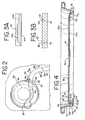
- Figure 1 is a top view of a can end of the present invention without a tab;
- Figure 1A is a top view of the can end of Figure 1 with a tab staked thereto;
- Figure 2 is a partial top view of the can end of Figure 1;
- Figure 3A is a partial cross-sectional view of taken along 3A-3A of Figure 2;
- Figure 3B is a partial cross-sectional view of taken along 3B-3B of Figure 2;
- Figure 4 is a cross-sectional view of the can end of Figure 1 taken along 4-4;
- Figure 5 is a partial view of a deboss panel of the present invention; and
- Figure 6 is a top view of a can end of the present invention without a tab.
- While this invention is susceptible of embodiment in many different forms, there are shown in the drawings and will herein be described in detail preferred embodiments of the invention with the understanding that the present disclosure is to be considered as an exemplification of the principles of the invention and is not intended to limit the broad aspect of the invention to the embodiments illustrated.
- The container end of the present invention is a stay-on-
tab end member 10 with improved physical properties including strength. Essentially, the present invention provides alightweight end member 10 which embodies the physical characteristics and properties required in the beverage container market, as explained below. - In the embodiment of Figures 1 through 6, the
end member 10 for a container (not shown) has acentral panel wall 12 having aseaming curl 14 for joining the wall to the container. The container is typically a drawn and ironed metal can, usually constructed from a thin plate of aluminum or steel, such as the common beer and beverage containers. End closures for such containers are also typically constructed from a cut edge of thin plate of aluminum or steel, formed into blank end, and manufactured into a finished end by a process often referred to as end conversion. In the embodiment shown in the Figures, thecentral panel 12 is joined to a container by aseaming curl 14 which is joined to a mating curl of the container. Theseaming curl 14 of theend closure 10 is integral with thecentral panel 12 by acountersink area 16 which is joined to the panel outerperipheral edge 18 of thecentral panel 12. This type of means for joining thecentral panel 12 to a container is presently the typical means for joining used in the industry, and the structure described above is formed in the process of forming the blank end from a cut edge of metal plate, prior to the end conversion process. However, other means for joining thecentral panel 12 to a container may be employed with the present invention. - The outer
peripheral edge 18 of thecentral panel 12 is typically coined to add strength to can end 10. Coining is the work hardening of metal between tools. The metal is typically compressed between a pair of tools, generally an upper and lower tool. - The
central panel wall 12 has adisplaceable tear panel 20 defined by a curvilinearfrangible score 22 with an adjacentanti-fracture score 24 on thetear panel 20, and anon-frangible hinge segment 26. Thehinge segment 26 is defined by a generally straight line between afirst end 28 and asecond end 30 of thefrangible score 22. Thetear panel 20 of thecentral panel 12 may be opened, that is thefrangible score 22 may be severed and thetear panel 20 displaced at an angular orientation relative to the remaining portion of thecentral panel 12, while thetear panel 20 remains hingedly connected to thecentral panel 12 through thehinge segment 26. In this opening operation, thetear panel 20 is displaced at an angular deflection, as it is opened by being displaced away from the plane of thepanel 12. - The first and
second ends frangible score 22 are joined by acurvilinear segment 32. Thecurvilinear segment 32 includes first and secondcurved segments arcuate transition region 34. which lies adjacent the outerperipheral edge 18 of thecenter panel 12 and are defined by a radius of curvature R4. (See Figure 5). The first and secondcurved segments - As best shown in Figure 3B, the
frangible score 22 is preferably a generally V-shaped groove 35 formed into the public side 34a of thepanel wall 12. Similarly, theanti-fracture score 24, is preferably a generally V-shaped groove 38 formed into the public side 34a of thepanel wall 12 on thetear panel 20. As is explained in more detail below, thefrangible score groove 35 is preferably deeper than theanti-fracture score groove 38. Accordingly, the score residual 40, being the amount of frangible material remaining below thefrangible score groove 35, is less than the adjacent anti-fracture score residual 42. This difference between score residual 40 and adjacent anti-fracture score residual 42 is the score residual differential. - The
frangible score 22 and the second groove oranti-fracture score 24 are formed using conventional-type of scoring operation during the can end forming process, using tools including an upper (public side) die with a score knife and a lower (product side) die with an anvil surface. - The score residual differential is adapted to provide a
tear panel 20 with ascore 22 more readily frangible than theanti-fracture score 24, a significant factor for providing efficient opening of theend member 10. Having a double score of afrangible score 22 and ananti-fracture score 24 wherein there is a score residual differential is common in the industry. - As illustrated in Figure 1A,
end member 10 has a tab 44 secured to theend panel 12 by arivet 46. The tab 44 has alift end 48, acentral region 50, and a nose portion 52. Thelift end 48 and the nose portion 52 are generally aligned along a central longitudinal axis passing through therivet 46. Abead 56 is optionally formed in thetear panel 20 inward of thescore 22 and theanti-fracture score 24. Thetear panel bead 56 is useful to draw excess metal, or slack of metal, from thetear panel 20 to tighten the metal of thetear panel 20 and improve opening characteristics of theend member 10 by the tab 44 being lifted to push against thetear panel 20. - The
rivet 46 is formed in the typical manner. It is the conventional practice to coin the metal on thecentral panel 12 proximate the base of therivet 46 during formation thereof. When therivet 46 is completely formed in thecentral panel 12, a coinedregion 58 having a generally circular periphery is also formed and is located about therivet 46. This coinedregion 58 is typically called a button coin. - The user initiates opening of the
end member 10 by lifting thelift end 48 of the tab 44. This lifts therivet 46 which causes thescore groove 22 to fracture in avent region 60 which is located at least partially within the bounds of the coined region surrounding therivet 46. As the nose portion 52 presses against thetear panel 20, the fracture of thescore 22 propagates around thetear panel 20, preferably in progression from thefirst end 28 of thescore 22 toward thesecond end 30 of thescore 22. - The
frangible score 22 includes a length defined by a thickened portion of the residual. This length is often referred to as acheck slot region 62. As illustrated in Figure 3A, thecheck slot 62 includes an area of thickened residual 64. The area thickened residual 64 causes the propagation of the fracture of thefrangible score 22 to slow naturally as the fracture reaches thecheck slot region 62. This allows the container to vent safely before the fracture of thefrangible score 22 continues. - Typically, the
check slot 62 is located within the bounds of the coinedregion 58. Thecheck slot 62, however, is located beyond the boundary of the coinedregion 58. Thus, thecheck slot 62 is not located within the thinned metal of the coinedregion 58 surrounding therivet 46. This is advantageous for reasons which will be discussed below. - Preferably, the
check slot region 62 includes a duel step residual differential. (See Figure 3A). The dual step residual differential includes two levels of residual thickness. Thus, thecheck slot region 62, rather than having a constant residual thickness, includes a first step 63a wherein the residual differential between the first step 63a and substantially the remaining portions of thefrangible score 22 is approximately 0.0508 mm (0.002 inches) and asecond step 63b wherein the residual differential between thesecond step 63b and substantially the remaining portions of thefrangible score 22 is approximately 0.04064 mm (0.0016 inches) thick. - The
end member 10 also includes avent coin 65. Thevent coin 65 is a small rectangularly shaped coin placed near thefrangible score 22. Thevent coin 65 has aleading end 66 placed adjacent thefrangible score 22 and a trailingend 67 directed outwardly and at an angle from thefrangible score 22. Anintermediate section 68 of thevent coin 65 intersects theanti-fracture score 24. - One purpose of the
vent coin 65 is to prevent thetear panel 20 from missiling during the opening of the container. Missiling is a jutting upward of thetear panel 20 upon venting. Missiling is caused when thefrangible score 22 fracture propagates beyond thevent region 60, before the container pressure is fully relieved. Theloose tear panel 20 is then forced upward due to the internal pressure of the container. - The
end member 10 is opened by the lifting of the rivet and subsequently by the force of the tab 44 pushing down on thetear panel 20. Initially, thefrangible score 22 should only be severed in thevent region 60. This allows a small portion of thetear panel 20 metal to be pushed below thecentral panel 12 to open and vent the pressure within the container. - The
vent coin 65 functions by displacing metal near the juncture of thecheck slot 62 and thevent region 60. The displaced metal in the area causes an elastic, compressive state. As such, when thefrangible score 22 is severed in thevent region 60, the metal of thetear panel 20 springs out to underlap the metal of thecentral panel 12 in that region. This underlapping portion of thetear panel 20 is believed to keep the remainder of thetear panel 20 in place so as to avoid premature fracture of the remainder of thefrangible score 22 and thereby prevent thetear panel 20 from missiling. - Typically, the
vent coin 65 is located within the coinedregion 58. Similar to the check shot 62, thevent coin 65 is moved outside of the periphery of the coinedregion 58 surrounding therivet 46. It is believed that by moving thevent coin 62 outside of the coinedregion 58 boundary, the compressive stress on thefrangible score 22 is increased. Therefore, the depth offrangible score 22 in thevent region 60 may be increased, and the strength requirement of the tab 44 to begin fracture of thefrangible score 22 can be decreased. - The
vent coin 65 also interacts with thecheck slot 62 to slow the propagation of the fracture along thefrangible score 22 during venting of the container. - According to another aspect of the present invention, a
deboss panel 69 is formed in the public side 34a of thecentral panel 12. Thedeboss panel 69 is formed in thecentral panel 12 using conventional die-forming techniques. As shown in Figures 1 and 1A, thedeboss panel 69 has a substantially gibbous-shapeddeboss profile 70 which is, in turn, defined by aninner radius line 72 and anouter radius line 74. As illustrated in Figure 4, theouter radius line 74 may have a radius of curvature of about 0.381 mm (0.015 inches) with a center of curvature below aproduct side 34b of thecentral panel 12 and theinner radius line 72 may have a radius of curvature of 0.381 mm (0.015 inches) with a center of curvature above public side 34a of thecentral panel 12. The depth of thedeboss profile 70, i.e., the vertical distance betweenouter radius line 74 andinner radius line 72 may be about 0.4826 mm (0.019 inches). The width of the deboss profile, i.e., the lateral distance between the outer andinner radius lines deboss panel 69 has bilateral symmetry with respect to a plane defined by axes X-X and Y-Y. - The
deboss profile 70 includes first and secondopposing end portions sidewalls 80a, 80b. Thefirst end portion 76 includes an apex 82. The apex 82 is joined to thesidewalls 80a, 80b by first and secondarcuate portions transition region 34 of thefrangible score 22 and the outerperipheral edge 18 of thecenter panel 12. The first and secondarcuate portions secant lengths 88a-88d arranged parallel to the Y-Y axis and opposite the apex 82 become progressively longer in length until the first and secondarcuate portions sidewalls 80a, 80b. (See Figure 5). The apex 82 may also be described as having a radius of curvature R5 wherein thearcuate portions respective sidewall 80a, 80b. - It should be noted that in the embodiment illustrated in Figure 5, the
sidewalls 80a, 80b are substantially straight segments. Thesidewalls 80a, 80b, however, may curvilinear or any shape. For instance, Figure 6 illustrates sidewalls 80a, 80b having a curvilinear shape. - Typically, the
deboss profile 70 and thefrangible score 22 remain equidistant throughout thefirst end portion 76. The distance between thefrangible score 22 and thefirst end portion 68 of thedeboss profile 70 is generally on the order of 1.27mm (0.05 inches). - As illustrated in Figure 5, the present invention discloses a widening of the distance between the
first end portion 76 of thedeboss profile 70 and thecurved segments frangible score 22. At the apex 82 of thefirst end portion 76, the distance D0 between thedeboss profile 70 and thefrangible score 22 is about 1.27mm (0.05 inches). The distances D1- D3 increase gradually as the ratio of thesecant lengths 88a-88d of thedeboss profile 70 to the chordal lengths 31a-33d of thefrangible score 22 increases. At the points where the first and secondarcuate portions deboss profile 70 and thefrangible score 22 is about 2.54mm (0.1 inches). - An alternative embodiment is illustrated in Figure 6. In this embodiment, the distance between the
deboss profile 70 and thefrangible score 22 is increased from 1.27mm (0.050 inches) to approximately 2.54mm (0.1 inches). The distance is preferably maintained at 0.1 inches but also may be within the range of 1.27-2.54mm (0.05-0.1 inches), or any range or combination of ranges therein. - The relationship between the
deboss panel 69 and thefrangible score 22 is important. Thedeboss panel 69 takes up metal displaced during the scoring process and the coining of theperipheral edge 18. Also, by moving thedeboss panel 69 outwardly from thefrangible score 22, it is believed that the stresses created on thefrangible score 22 during the forming of thedeboss panel 69 are greatly reduced. This is believed to enhance score rupturing by taking up metal slack near therivet 46 and also immediately adjacent to thefrangible score 22 along its entire length from the 6 o'clock past the 9 o'clock position, the region where score rupture failure is most likely to occur. Thus, the widening of thedeboss panel 69 also increases burst values by relieving the stresses on thefrangible score 22. Theend member 10 is also strengthened because the movement of thedeboss panel 69 outwardly allows the panel to be recessed deeper, taking up even more loose metal. - Generally, the
central panel 12 experiences stress gradients. As the distance from the rivet 46 (center of the central panel 12) becomes greater, the stress lessens. Thus, by moving thedeboss panel 69 away from thefrangible score 22, the component of stress supplied by thedeboss panel 69 is reduced. Thus, the depth offrangible score 22 may be increased as much as 50% without incurring premature failure of thefrangible score 22. - As illustrated in Figures 5 and 6, a
curvilinear bead 89 may be formed in the public side 34a of thecentral panel 12. Thebead 89 is preferably formed to have a curvilinear length, adapted to at least partially surround the coinedregion 58, thereby partially surrounding therivet 46. Further, thebead 89 is preferably an emboss bead or a raised portion in the public side 34a of thecentral wall 12. - The
bead 89 provides the desirable stiffness of thecentral panel 12 in the region around therivet 46, thereby reducing the amount of panel lift resulting from the force of the tab 44 on thetear panel 20 during opening. The stiffness of thetear panel 20 is primarily provided by thebead 89 being formed as drawn metal in the public side 34a of thecentral panel 12 immediately adjacent the coinedregion 58 and therivet 46. - The
bead 89 preferably has an arcuate portion and a substantially linear portion. The arcuate portion partially surrounds the coinedregion 58, extending a slightly longer distance on one side of the coinedregion 58 than on an opposing side of the coinedregion 58. This allows thefirst end 28 of thescore 22 to extend upwardly so that it wraps slights around therivet 46. The substantially linear portion is located on an opposite side of the coinedregion 58 as thefrangible score 22. - Preferably, there is very little thinning of the metal during formation of the
bead 89, and thebead 89 is instead created by forming or drawing the metal between two opposed dies to take up slack metal. Thebead 89 formation thereby draws available loose metal in the region, such as loose metal caused by scoring, coining of the metal while forming therivet 46, or coining of metal while staking the tab 44. Thebead 89 also serves as a stiffening beam in thepanel 12 wall immediately adjacent therivet 46 and the coinedregion 58. By drawing loose metal and providing a stiffening beam, thebead 89 is adapted to provide stiffness in thepanel wall 12 around the coinedregion 58 to decrease the panel lift and enhance the leverage by the tab 44 during opening of theend tear panel 20. - Referring to Figure 4, the
countersink 16 of theend member 10 includes aninner wall 90, a curved segment 92, and anouter wall 94. The curved segment 92 has an inner arcuate portion 96 joined to an outer arcuate portion 98 along anannular base 100. Theinner wall 90 has anupper portion 102 joined to the outerperipheral edge portion 18 of thecentral panel 12 and alower portion 104 joined to the inner arcuate portion 96 of the curved segment 92. Theouter wall 94 has a lower portion 106 joined to the outer arcuate portion 98 of the curved segment 92, acrease portion 108 angled outwardly of thecentral panel 12, and anupper portion 110. Thecrease 108 has a radius of curvature of approximately 0.127 mm (0.005 inches) and is positioned at a height H1 of approximately 1.651mm (0.065) inches above theannular base 100. - The outer
peripheral edge 18 of thecentral panel 12 includes a stepped profile. The stepped profile includes afirst panel radius 114 interconnected to asecond panel radius 116 by the previously coined portion of the outerperipheral edge 18. Thefirst panel radius 114 has a height H2 which is approximately 0.108 inches above theannular base 100. Thesecond panel radius 116 is joined to theinner wall 90 of thecountersink 16 and has a height H3 which is approximately 0.093 inches above theannular base 100. - The dimensions of the
first panel radius 114, thesecond panel radius 116, and thecrease portion 108 were selected to optimize resistance to burst and tab-over-chime. Burst is the ability of the pourpanel 20 to withstand internal pressure. Tab-over-chime is also the ability of theend member 10 to withstand internal pressure. Tab-over-chime occurs when the internal pressure forces the tab 44 upwardly. When the tab 44 is displaced upward, it can lead to ship abuse during distribution of filled containers which can cause premature failure of the pourpanel 20. Thus, tab-over-chime is the internal pressure at which the tab is displaced an undesirable amount. - As the height H3 of the
second panel radius 116 increases, buckle values increase; however, the tab-over-chime value decreases as the height H3 of thesecond panel radius 116 increases. Thus, the height H1 of thecrease portion 108 can be 1.524-1.905 mm (0.060-0.075 inches) or any height or range of heights therein, and the height H3 of thesecond panel radius 116 can be 2.032-2.4130 mm (0.080-0.095 inches) or any height or range of heights therein. It should be noted that for forming reasons, the height H1 of thecrease 108 is preferably lower than the height H3 of thesecond panel radius 116. - According to another aspect of the invention a method for reforming a can end shell to produce the
end member 10 described herein is disclosed. The method is used to produce alightweight end member 10, for example from an 0.2032 mm (0.0080 inch) thick aluminum stock for attachment to a container necked to a 202 53.975 mm (2.125 inches) open end.End members 10 of the present invention are generally manufactured using a multi-stage reforming method. - In an the initial stage, the outer
peripheral edge 18 of thecentral panel 12 is coined and reformed in the conventional manner as disclosed, for example, inU.S. Patent No. 5,527,442 . The coining operation creates slack metal produced by the compression of theperipheral edge 18 between the coining tools. This coining operation forces metal in the outer peripheral edge to flow both radially inwardly and radially outwardly from theperipheral edge 18. - The slack metal is removed as the
countersink 16 is reformed. In this operation, thecountersink 16 is reformed so that metal in thecountersink 16 is moved downwardly with respect to thecentral panel 12. This decreases thecountersink 16 depth which causes thecentral panel 12 height to increase. To further improveend member 10 rock and buckle performance, the outer wall of thecountersink 16 may also be creased or kinked radially outwardly, as illustrated in Figure 4, during the reforming operation. This type of operation is disclosed inU.S. Patent 4,093,102 . - Next, the
deboss panel 69 is formed within thecentral panel 12. The forming of thedeboss panel 69 places thecentral panel 12 into the desirable tension state. Thedeboss panel 69 also takes up any slack metal created during the coining of theperipheral edge 18 and the scoring of thecentral panel 12 when thefrangible score 22 and theanti-fracture score 24 are formed. - Once the tab 44 has been staked to the
rivet 46, the step portion is formed at the outerperipheral portion 18. The step portion increases the height of thecentral panel 12 above that of the initial reform increase. The forming of the step portion increases the end member's 10 buckle resistance even higher. Also, since no slack metal is remaining from the coining and scoring operations, it has been found that thedeboss panel 69 will roll up or the recess will become shallower subsequent to the step portion being formed. - In an initial trial, can ends 10 were produced with a
check slot region 62 having a single step of residual thickness of 0.04064 mm (0.0016 ins), avent coin 65 positioned below theanti-fracture score 24, and a 6:00 - 12:00 score residual differential of only 0.00508-0.01016mm (0.0002- 0.0004 ins). This trial resulted in improved openability. - A second trial was carried out on can ends 10 as illustrated in Figures 5. The lengths of increased residual 62 of these can ends 10 were modified to create the dual step residual differential to the
frangible score 22 of 0.0508 and 0.04064 mm (0.0020 ins. and 0.0016 ins). All of the can ends 10 exhibited improved openablility and passed the missiling test. It is believed that these favorable results are attributable to thetear panel 20 hinging at, or opening to, thevent coin 65 when the can end 10 end is "popped" or when opening is initialized. This creates a larger vent opening and allows the can end 10 to vent and pass the missiling test. - Since the can ends 10 successfully passed the missiling test, a complete evaluation was performed. Further tests on a total of eight sets of can ends 10, as illustrated in Figures 1-4 were performed. All of the forming variables of the eight sets of can ends 10 were identical except for the score residuals of the
frangible score 22. The different score residuals are summarized in Table 1.Table 1: Score Residuals in millimetres (and in inches) Test Group Residual at the 12:00 Position Residual at the 3:00 Position Residual at the 9:00 Position Residual at the 6:00 Position A 0.0762 0.07366 0.07366 0.07112 (0.003) (0.0029) (0.0029) (0.0028) B 0.08382 0.08382 0.08382 0.08128 (0.0033) (0.0033) (0.0033) (0.0032) C 0.08636 0.08636 0.08636 0.08128 (0.0034) (0.0034) (0.0034) (0.0032) D 0.09144 0.0889 0.0889 0.08636 (0.0036) (0.0035) (0.0035) (0.0034) E 0.09652 0.09398 0.09398 0.0889 (0.0038) (0.0037) (0.0037) (0.0035) F 0.10668 0.10668 0.10668 0.1016 (0.0042) (0.0042) (0.0042) (0.004) G 0.1143 0.11176 0.11176 0.10414 (0.0045) (0.0044) (0.0044) (0.0041) H 0.11938 0.11684 0.11684 0.10922 (0.0047) (0.0046) (0.0046) (0.0043) - The can ends 10 were also tested for pressurized openability (for beer). No failures were found until test group H.
- The can ends 10 were further tested for score burst. None of the can ends 10 burst open before the maximum pressure of the test was reached. It is believed that the excellent results of this test are directly attributable to the greater distance from the
deboss panel 69 to thefrangible score 22.
Claims (9)
- An end member (10) for a container, the end member (10) having a central panel wall (12) with a product side (34a) and a public side (34b), the public side (34a) having a means for opening a frangible panel segment (20), the end member comprising:a deboss panel (69) recessed in the central panel (12), the deboss panel having a profile (70) defined by first and second spaced apart end portions (76,78) joined by first and second sidewalls (80a,80b);a displaceable tear panel (20) defined by a curvilinear frangible score (22) and a non-frangible hinge segment (26), the score groove (22) having a first end (28) and a second end (30), the hinge segment (26) is defined by a generally straight line between the first end (28) and the second end (30) of the score groove (22),the first and second ends (28,30) of the frangible score (22) being joined by a curvilinear segment (32), the curvilinear segment (32) including first and second curved segments (33a,33b) defined by a radius of curvature and joined by an arcuate transition region (34) which lies adjacent to the outer peripheral edge (18) of the center panel (12),the first spaced apart end portion (76) of the deboss panel (69) having first and second arcuate portions (84a, 84b) extending outwardly from an apex (82) characterised in that the distance between the score groove (22) and the deboss profile (70) becomes progressively longer from the apex (82) along at least the first or second arcuate portion (84a, 84b).
- The end member (10) of Claim 1 wherein the minimum distance between the deboss profile and the score groove is greater than 0.127 cm (0.050 inches).
- The end member (10) of Claim 2 wherein the distance between the deboss profile (70) and the score groove (22) is between 0.127 cm and 0.254 cm (0.050 inches and 0.1 inches).
- The end member (10) of any preceding claim further comprising:a rivet (46) located within the deboss panel (69) and adapted to integrally attach a tab lever (44) to the panel (69), the tab lever (44) having a nose portion (52) overlying at least a portion of the frangible panel (20) and having a lift end (48) opposite the nose portion (52); anda coined region (58) having an outer periphery located about the rivet (46) wherein the score groove (22) has a portion separated from the product side (34b) of the central panel (12) by a residual (40), and the score groove (22) includes a vent region (60)located within the coined region (58) and adjacent the rivet (46), and a length defined by a thickened portion of the residual (64) located beyond the periphery of the coined region (58) wherein the frangible panel segment (20) initially opens within the vent region (60) in response to a pulling force on the lift end (48) of the tab lever (44).
- The end member (10) of Claim 4 further comprising a vent coin (65) adjacent the length of the score groove (22) defined by a thickened portion of the residual (64) for placing a compressive stress on the length of the score groove (22) defined by a thickened portion of the residual (64).
- The end member (10) of Claim 4 or Claim 5 further comprising an anti-fracture score (24) adjacent the score groove (22) wherein the vent coin (65) intersects the anti-fracture score (24).
- The end member (10) of any preceding claim wherein the central panel (12) has an outer peripheral edge segment (18) including a stepped portion having at least a first panel radius (116) interconnected to a second panel radius (114).
- The end member (10) of Claim 7 further comprising a countersink portion (16) connected to the central panel by the outer peripheral edge portion (18), the countersink (16) including an inner wall (90), a curved segment (92), and an outer wall (94), the curved segment (92) having an inner arcuate portion (96) joined to an outer arcuate portion (98) along an annular base (100), the inner wall (90) having an upper portion (102) joined to the outer peripheral edge portion (18) of the center panel (12) and a lower portion joined to the inner portion of the curved segment, and the outer wall (94) having a lower portion joined to the outer portion of the curved segment (98), a crease portion angled (108) outwardly of the center panel (12), and an upper portion wherein the crease (108) is positioned at a first height (H1) above the annular base (100) and the second panel radius (114) is positioned at a second height (H2), the second height (H2) being greater than the first height (H1).
- A method of producing the end member (10) of any one of claims 1 to 8, the method comprising the steps of:providing an end member (10) including a central panel wall (12) with a product side (34a) and a public side (34b), a countersink (16), and an outer peripheral edge (18);forming the score groove (22) within the central panel (12);coining the outer peripheral edge (18) of the central panel (12);reforming the countersink (16) downwardly with respect to the central panel (12);forming the deboss panel (69) within the central panel (12) and spaced from the outer peripheral edge (18); andreforming the outer peripheral edge (18) of the end member wherein the outer peripheral edge portion (18) includes a first panel radius (116) interconnected to a second panel radius (114).
Priority Applications (2)
| Application Number | Priority Date | Filing Date | Title |
|---|---|---|---|
| EP07115237A EP1857196B1 (en) | 2000-12-27 | 2001-12-04 | Can end for a container |
| EP07115235A EP1857370B1 (en) | 2000-12-27 | 2001-12-04 | Can End for a Container |
Applications Claiming Priority (3)
| Application Number | Priority Date | Filing Date | Title |
|---|---|---|---|
| US748927 | 2000-12-27 | ||
| US09/748,927 US20020113069A1 (en) | 2000-12-27 | 2000-12-27 | Can end for a container |
| PCT/US2001/046786 WO2002051710A1 (en) | 2000-12-27 | 2001-12-04 | Can end for a container |
Related Child Applications (2)
| Application Number | Title | Priority Date | Filing Date |
|---|---|---|---|
| EP07115235A Division EP1857370B1 (en) | 2000-12-27 | 2001-12-04 | Can End for a Container |
| EP07115237A Division EP1857196B1 (en) | 2000-12-27 | 2001-12-04 | Can end for a container |
Publications (3)
| Publication Number | Publication Date |
|---|---|
| EP1353852A1 EP1353852A1 (en) | 2003-10-22 |
| EP1353852A4 EP1353852A4 (en) | 2005-08-31 |
| EP1353852B1 true EP1353852B1 (en) | 2007-11-07 |
Family
ID=25011494
Family Applications (3)
| Application Number | Title | Priority Date | Filing Date |
|---|---|---|---|
| EP07115235A Expired - Lifetime EP1857370B1 (en) | 2000-12-27 | 2001-12-04 | Can End for a Container |
| EP07115237A Expired - Lifetime EP1857196B1 (en) | 2000-12-27 | 2001-12-04 | Can end for a container |
| EP01995390A Expired - Lifetime EP1353852B1 (en) | 2000-12-27 | 2001-12-04 | Can end for a container |
Family Applications Before (2)
| Application Number | Title | Priority Date | Filing Date |
|---|---|---|---|
| EP07115235A Expired - Lifetime EP1857370B1 (en) | 2000-12-27 | 2001-12-04 | Can End for a Container |
| EP07115237A Expired - Lifetime EP1857196B1 (en) | 2000-12-27 | 2001-12-04 | Can end for a container |
Country Status (10)
| Country | Link |
|---|---|
| US (2) | US20020113069A1 (en) |
| EP (3) | EP1857370B1 (en) |
| CN (1) | CN1315697C (en) |
| AT (3) | ATE457839T1 (en) |
| BR (1) | BR0116603B1 (en) |
| DE (3) | DE60131296T2 (en) |
| ES (2) | ES2345007T3 (en) |
| MX (1) | MXPA03005928A (en) |
| RU (1) | RU2283265C2 (en) |
| WO (1) | WO2002051710A1 (en) |
Families Citing this family (51)
| Publication number | Priority date | Publication date | Assignee | Title |
|---|---|---|---|---|
| US7556168B2 (en) * | 2001-08-16 | 2009-07-07 | Rexam Beverage Can Company | Can end with fold |
| US7004345B2 (en) * | 2001-08-16 | 2006-02-28 | Rexam Beverage Can Company | Can end |
| US6715629B2 (en) * | 2001-12-19 | 2004-04-06 | Rexam Beverage Can Company | Can end for a container |
| KR200289188Y1 (en) | 2002-06-11 | 2002-09-13 | 전정욱 | Readily openable can lid |
| US6761281B2 (en) | 2002-11-26 | 2004-07-13 | Rexam Beverage Can Company | Modified score for smooth openability |
| USD600116S1 (en) * | 2003-09-19 | 2009-09-15 | Gabe Cherian | Lid with pull tab |
| USD612724S1 (en) * | 2003-09-19 | 2010-03-30 | Gabe Cherian | Lid with pull tab |
| USD579771S1 (en) * | 2004-09-14 | 2008-11-04 | Gabe Cherian | Lid with pull tab |
| US7975884B2 (en) * | 2006-07-12 | 2011-07-12 | Alcoa Inc. | Vent tube for liquid container |
| US8511125B2 (en) * | 2007-05-31 | 2013-08-20 | Rexam Beverage Can Company | Flexible necking station arrangement for larger beverage cans |
| UA99944C2 (en) * | 2008-01-18 | 2012-10-25 | Краун Пекеджинг Текнолоджи, Инк. | Can end |
| USD600118S1 (en) * | 2008-06-02 | 2009-09-15 | Crown Packaging Technology, Inc. | Can end |
| USD600117S1 (en) * | 2008-06-02 | 2009-09-15 | Crown Packaging Technology, Inc. | Can end |
| USD600552S1 (en) * | 2008-06-27 | 2009-09-22 | Predrag Subotic | Beverage can cap |
| ES2366162T3 (en) | 2008-09-04 | 2011-10-17 | Crown Packaging Technology, Inc | CAN COVER. |
| US8397935B2 (en) | 2009-09-10 | 2013-03-19 | Arthur Joseph Emanuele, III | Vent opening mechanism |
| JO3303B1 (en) | 2009-10-30 | 2018-09-16 | Crown Packaging Technology Inc | Vented beverage can end |
| US8678221B2 (en) | 2010-04-28 | 2014-03-25 | Crown Packaging Technology, Inc. | Beverage container lid with mouth opening and separate push in vent |
| AU334953S (en) * | 2010-07-15 | 2011-02-01 | Showa Aluminum Can Corp | End panel for cans |
| US8567158B2 (en) | 2010-08-06 | 2013-10-29 | Ball Corporation | Container end closure with optional secondary vent opening |
| US10017295B2 (en) | 2010-08-06 | 2018-07-10 | Ball Corporation | Container end closure with optional secondary vent opening |
| USD650278S1 (en) * | 2010-10-29 | 2011-12-13 | Crown Packaging Technology, Inc. | Vented beverage can end |
| USD650277S1 (en) * | 2010-10-29 | 2011-12-13 | Crown Packaging Technology, Inc. | Vented beverage can end |
| USD650276S1 (en) * | 2010-10-29 | 2011-12-13 | Crown Packaging Technology, Inc. | Vented beverage can end |
| US8783495B2 (en) | 2011-02-14 | 2014-07-22 | Rexam Beverage Can Company | Can end |
| USD691039S1 (en) | 2011-10-27 | 2013-10-08 | Ball Corporation | Vented container end closure |
| ES2749348T3 (en) | 2011-11-04 | 2020-03-19 | Ball Corp | Closing the end of a vented metal container |
| BR112014027452A2 (en) | 2012-05-04 | 2017-06-27 | Ball Corp | metal terminal closure with tear panel having greater firmness |
| USD704555S1 (en) * | 2012-07-18 | 2014-05-13 | German Chavez Hernandez | Beverage can |
| USD715144S1 (en) | 2012-11-13 | 2014-10-14 | Ball Corporation | Vented container end closure |
| USD715647S1 (en) | 2012-11-28 | 2014-10-21 | Ball Corporation | Vented end closure |
| US9181007B2 (en) * | 2013-03-12 | 2015-11-10 | Rexam Beverage Can Company | Beverage can end with vent port |
| US9403628B2 (en) | 2013-03-14 | 2016-08-02 | Crown Packaging Technology, Inc. | Vented beverage can and can end |
| US10246229B2 (en) | 2013-03-14 | 2019-04-02 | Crown Packaging Technology, Inc. | Vented beverage can and can end |
| US9033175B2 (en) | 2013-03-15 | 2015-05-19 | Ball Corporation | End closure with double anti-missile score |
| US9694935B2 (en) | 2013-03-15 | 2017-07-04 | Ball Corporation | End closure with a ring pull actuated secondary vent |
| US20150353228A1 (en) * | 2013-06-10 | 2015-12-10 | Adam Herriott | Can/flass soda can. The new can opening. |
| US9714114B2 (en) * | 2013-11-08 | 2017-07-25 | Crown Packaging Technology, Inc. | Full aperture can end |
| ES2525589B1 (en) * | 2014-05-28 | 2015-07-28 | Saturnino CASTILLO OÑATE | Double opening system for beverage cans through a single drive of its ring |
| CA2956783C (en) | 2014-07-30 | 2018-05-29 | Ball Corporation | Vented container end closure |
| ES2786187T5 (en) * | 2014-12-01 | 2024-09-24 | Trivium Packaging Group Netherlands B V | Closure for a container and a container provided with the same |
| WO2017019269A1 (en) * | 2015-07-29 | 2017-02-02 | Ball Corporation | Container end closure with optional secondary vent opening |
| US9950832B2 (en) * | 2015-07-31 | 2018-04-24 | Rexam Beverage Can Company | Beverage can end frangible score geometry |
| JP6836895B2 (en) * | 2016-12-22 | 2021-03-03 | ユニバーサル製缶株式会社 | Can lid |
| USD796953S1 (en) | 2017-05-01 | 2017-09-12 | Chris Katopis | Paw-themed tab container closure |
| USD796952S1 (en) | 2017-05-01 | 2017-09-12 | Chris Katopis | Paw-themed tab container closure |
| US20190060977A1 (en) * | 2017-08-23 | 2019-02-28 | Stolle Machinery Company, Llc | Can end with a coined rivet, tooling assembly therefor and a method of forming |
| USD956555S1 (en) * | 2017-12-07 | 2022-07-05 | Crown Packaging Technology, Inc. | Cap with tab |
| US12263989B2 (en) | 2020-07-13 | 2025-04-01 | Oc Bev Ltd | Lid for containers of substances, and container of substances comprising said lid |
| US12497210B2 (en) | 2023-03-27 | 2025-12-16 | Ram Solutions Llc | End cap with score line for controlled flap opening and method therefor |
| WO2026035811A1 (en) * | 2024-08-09 | 2026-02-12 | Ball Corporation | Metal container closure with missile control features and tooling set up therefor |
Family Cites Families (127)
| Publication number | Priority date | Publication date | Assignee | Title |
|---|---|---|---|---|
| US3215305A (en) | 1963-09-27 | 1965-11-02 | Continental Can Co | Wire opener fulcrumed on can-end for breaking scored segment thereof |
| US3259265A (en) | 1964-02-27 | 1966-07-05 | Crown Cork & Seal Co | Reseal for tab opening cans |
| US3291336A (en) | 1965-01-22 | 1966-12-13 | Ermal C Fraze | Can top |
| US3424337A (en) | 1966-07-12 | 1969-01-28 | Aluminum Co Of America | Container opening devices |
| US3583348A (en) * | 1968-03-29 | 1971-06-08 | Fraze Ermal C | Method of making an easy opening container wall |
| US4084721A (en) | 1972-03-02 | 1978-04-18 | The Continental Group, Inc. | Container with attached closure |
| US4062471A (en) | 1972-03-02 | 1977-12-13 | Perry Walter Merton | Container with attached closure |
| US3967752A (en) | 1972-09-28 | 1976-07-06 | Reynolds Metals Company | Easy-open wall |
| US3957005A (en) | 1974-06-03 | 1976-05-18 | Aluminum Company Of America | Method for making a metal can end |
| US4093102A (en) * | 1974-08-26 | 1978-06-06 | National Can Corporation | End panel for containers |
| US3941277A (en) | 1975-04-21 | 1976-03-02 | Van Dorn Company | Embossed can end construction |
| USD244915S (en) | 1975-08-20 | 1977-07-05 | Reynolds Metals Company | End closure for a container |
| US4030631A (en) | 1975-08-27 | 1977-06-21 | Ermal C. Fraze | Easy-open ecology end |
| US4015744A (en) | 1975-10-28 | 1977-04-05 | Ermal C. Fraze | Easy-open ecology end |
| US4031837A (en) | 1976-05-21 | 1977-06-28 | Aluminum Company Of America | Method of reforming a can end |
| US4024981A (en) * | 1976-07-01 | 1977-05-24 | Ermal C. Fraze | Easy-open ecology end |
| US4061243A (en) | 1976-11-02 | 1977-12-06 | The Continental Group, Inc. | End closure with variable size pour opening |
| US4217843A (en) | 1977-07-29 | 1980-08-19 | National Can Corporation | Method and apparatus for forming ends |
| GB1604068A (en) | 1977-07-29 | 1981-12-02 | Nat Can Corp | Metal container ends |
| US4109599A (en) | 1977-11-04 | 1978-08-29 | Aluminum Company Of America | Method of forming a pressure resistant end shell for a container |
| US4130219A (en) | 1977-11-21 | 1978-12-19 | The Continental Group, Inc. | Bead supported tab for non-detachable ends |
| USRE31702E (en) | 1978-01-30 | 1984-10-09 | Ermal C. Fraze | Tab for easy-open ecology end |
| US4175670A (en) | 1978-03-22 | 1979-11-27 | Reynolds Metals Company | Container construction |
| US4184607A (en) | 1979-01-29 | 1980-01-22 | Crown Cork & Seal Company, Inc. | Easy open can end |
| US4205760A (en) | 1979-02-12 | 1980-06-03 | The Continental Group, Inc. | Non-detach beverage end |
| US4210257A (en) | 1979-06-21 | 1980-07-01 | American Can Company | Fracture and tear-resistant retained tab |
| US4211335A (en) | 1979-06-21 | 1980-07-08 | American Can Company | Fracture resistant retained lever tab and method of manufacture |
| AU532786B2 (en) | 1979-08-13 | 1983-10-13 | Broken Hill Proprietary Company Limited, The | Push - in closure |
| USD266991S (en) | 1979-08-22 | 1982-11-23 | The Continental Group, Inc. | End closure for a container |
| US4276993A (en) | 1979-10-10 | 1981-07-07 | The Continental Group, Inc. | Easy-opening container with non-detach tab |
| USD265463S (en) | 1979-10-29 | 1982-07-20 | The Continental Group, Inc. | End closure for a container |
| USD263802S (en) | 1979-11-05 | 1982-04-13 | Fraze Ermal C | End closure for a container |
| USD263803S (en) | 1979-11-05 | 1982-04-13 | Fraze Ermal C | End closure for a container |
| US4266688A (en) | 1979-12-14 | 1981-05-12 | The Continental Group, Inc. | Easy access tab for vacuum packed products |
| AU541926B2 (en) | 1980-01-16 | 1985-01-31 | American Can Co. | Buckle resistant can end |
| US4790705A (en) | 1980-01-16 | 1988-12-13 | American National Can Company | Method of forming a buckle resistant can end |
| NL8005402A (en) | 1980-09-29 | 1982-04-16 | Thomassen & Drijver | A method for forming a peripheral edge protruded on a preformed metal cover. |
| US4320850A (en) * | 1980-10-24 | 1982-03-23 | The Continental Group, Inc. | Easy opening end unit with tapered score |
| USD267393S (en) | 1980-12-08 | 1982-12-28 | The Continental Group, Inc. | Can |
| US4361251A (en) | 1981-05-18 | 1982-11-30 | American Can Company | Detachment resistant retained lever tab |
| US4363419A (en) | 1981-09-08 | 1982-12-14 | Walz Sr Karl | Self-storing permanently attached can opening means |
| US4387827A (en) | 1981-11-27 | 1983-06-14 | Crown Cork & Seal Company, Incorporated | Container closure |
| USD275373S (en) | 1982-01-07 | 1984-09-04 | Ermal C. Fraze | End closure for a container |
| US4577774A (en) | 1982-03-11 | 1986-03-25 | Ball Corporation | Buckle resistance for metal container closures |
| US4434641A (en) | 1982-03-11 | 1984-03-06 | Ball Corporation | Buckle resistance for metal container closures |
| USRE33217E (en) | 1982-03-11 | 1990-05-15 | Ball Corporation | Buckle resistance for metal container closures |
| USD279265S (en) | 1982-04-14 | 1985-06-18 | National Can Corporation | End closure for a container |
| US4516420A (en) | 1983-06-10 | 1985-05-14 | Redicon Corporation | Shell tooling |
| EP0103074A3 (en) | 1982-09-09 | 1984-05-23 | Ball Corporation | Increased strenght for metal closures through reversing curved segments |
| US4549424A (en) | 1983-06-10 | 1985-10-29 | Redicon Corporation | Shell tooling method |
| US4530631A (en) | 1983-07-13 | 1985-07-23 | The Stolle Corporation | Pull tab for easy open can end-method of manufacture thereof |
| US4465204A (en) | 1983-07-13 | 1984-08-14 | The Stolle Corporation | Pull tab for easy open end |
| US4559801A (en) | 1983-10-26 | 1985-12-24 | Ball Corporation | Increased strength for metal beverage closure through reforming |
| US4641761A (en) | 1983-10-26 | 1987-02-10 | Ball Corporation | Increased strength for metal beverage closure through reforming |
| US4561280A (en) | 1984-01-16 | 1985-12-31 | Dayton Reliable Tool & Mfg. Co. | Shell making method and apparatus |
| US4862722A (en) | 1984-01-16 | 1989-09-05 | Dayton Reliable Tool & Mfg. Co. | Method for forming a shell for a can type container |
| US4704887A (en) | 1984-01-16 | 1987-11-10 | Dayton Reliable Tool & Mfg. Co. | Method and apparatus for making shells for can ends |
| US4735863A (en) | 1984-01-16 | 1988-04-05 | Dayton Reliable Tool & Mfg. Co. | Shell for can |
| US4606472A (en) | 1984-02-14 | 1986-08-19 | Metal Box, P.L.C. | Reinforced can end |
| US4571978A (en) | 1984-02-14 | 1986-02-25 | Metal Box P.L.C. | Method of and apparatus for forming a reinforced can end |
| US4722215A (en) | 1984-02-14 | 1988-02-02 | Metal Box, Plc | Method of forming a one-piece can body having an end reinforcing radius and/or stacking bead |
| US4610156A (en) | 1984-12-20 | 1986-09-09 | The Stolle Corporation | Progressive die apparatus having resilient tool support means |
| USD302116S (en) | 1985-05-13 | 1989-07-11 | Cassai Gino H | Beverage can |
| US4808052A (en) | 1986-07-28 | 1989-02-28 | Redicon Corporation | Method and apparatus for forming container end panels |
| US4716755A (en) | 1986-07-28 | 1988-01-05 | Redicon Corporation | Method and apparatus for forming container end panels |
| GB2193140B (en) | 1986-07-28 | 1990-08-15 | Redicon Corp | Forming container end panels |
| US4749100A (en) | 1986-09-02 | 1988-06-07 | Ray Eberhart | Sanitary lid for beverage cans |
| US4713958A (en) | 1986-10-30 | 1987-12-22 | Redicon Corporation | Method and apparatus for forming container end panels |
| JPH0624443B2 (en) | 1987-01-27 | 1994-04-06 | 三菱農機株式会社 | Work machine lift control device |
| US4733793A (en) | 1987-05-01 | 1988-03-29 | Adolph Coors Company | System for forming an opening in a container end member |
| US4804104A (en) | 1987-05-01 | 1989-02-14 | Adolph Coors Company | System for forming an opening in a container end member |
| US4832223A (en) | 1987-07-20 | 1989-05-23 | Ball Corporation | Container closure with increased strength |
| US4865506A (en) | 1987-08-24 | 1989-09-12 | Stolle Corporation | Apparatus for reforming an end shell |
| US4796772A (en) | 1987-09-07 | 1989-01-10 | Ball Corporation | Metal closure with circumferentially-variegated strengthening |
| DE3840251C2 (en) | 1987-11-30 | 2000-10-12 | Nickolaus Englert | Beverage container closure |
| GB8810229D0 (en) * | 1988-04-29 | 1988-06-02 | Metal Box Plc | Can end shells |
| JPH01308744A (en) | 1988-05-25 | 1989-12-13 | Nippon Steel Corp | Easily opening can lid with inseparable tab |
| US4872597A (en) | 1988-10-13 | 1989-10-10 | Hisao Hanafusa | Beverage container with dual dispensing tabs |
| US4994009A (en) | 1989-02-07 | 1991-02-19 | The Stolle Corporation | Easy open can end method of manufacture |
| US4930658A (en) | 1989-02-07 | 1990-06-05 | The Stolle Corporation | Easy open can end and method of manufacture thereof |
| US4930654A (en) | 1989-03-30 | 1990-06-05 | Thibeault Richard A | Resealable flip-top can |
| US4928844A (en) | 1989-04-14 | 1990-05-29 | Aluminum Company Of America | Pressure release for carbonated beverage containers |
| US4991735A (en) | 1989-05-08 | 1991-02-12 | Aluminum Company Of America | Pressure resistant end shell for a container and method and apparatus for forming the same |
| USD332750S (en) | 1989-05-12 | 1993-01-26 | American National Can Company | Can |
| USD319580S (en) | 1989-07-24 | 1991-09-03 | Henry J. Cassai | Beverage can |
| USD320153S (en) | 1989-07-24 | 1991-09-24 | Henry J. Cassai | Beverage can |
| USD318225S (en) | 1989-07-24 | 1991-07-16 | Henry J. Cassai | Beverage can |
| US5011037A (en) | 1989-11-30 | 1991-04-30 | Adolph Coors Company | Container end member |
| USD327424S (en) | 1990-05-07 | 1992-06-30 | Kip Pierce | Novelty beverage can |
| US5119664A (en) | 1990-11-19 | 1992-06-09 | Dayton Reliable Tool & Mfg. Co. | All purpose integral rivet and method of forming same |
| US5064087A (en) | 1990-11-21 | 1991-11-12 | Koch Systems Incorporated | Self-opening can lid with improved contour of score |
| US5287718A (en) | 1991-01-16 | 1994-02-22 | Toyo Saikan Kaisha, Ltd. | Curl forming method for a can end |
| US5149238A (en) * | 1991-01-30 | 1992-09-22 | The Stolle Corporation | Pressure resistant sheet metal end closure |
| US5129541A (en) * | 1991-06-04 | 1992-07-14 | Buhrke Industries, Inc. | Easy open ecology end for cans |
| USD338156S (en) | 1991-07-12 | 1993-08-10 | Cook Raymon W | End closure for a container |
| USD346745S (en) | 1991-09-24 | 1994-05-10 | American National Can Company | Fluted container |
| USD347172S (en) | 1991-09-24 | 1994-05-24 | American National Can Company | Fluted container |
| US5199591A (en) | 1991-11-21 | 1993-04-06 | Preferred Cantop Corporation | Resealable flip-top can |
| US5310476A (en) | 1992-04-01 | 1994-05-10 | Moltech Invent S.A. | Application of refractory protective coatings, particularly on the surface of electrolytic cell components |
| EP0564725B1 (en) | 1992-04-07 | 1998-07-01 | Toyo Seikan Kaisha, Ltd. | Anti-impact easily openable can lid and method of making the same |
| JP2607100Y2 (en) | 1992-10-09 | 2001-03-19 | 株式会社コムラ・アンド・カンパニー | Beverage cans |
| US5375729A (en) | 1993-04-21 | 1994-12-27 | Dayton Reliable Tool & Mfg. Co. | Easy-open container end |
| US5456378A (en) | 1993-07-01 | 1995-10-10 | Demars; Robert A. | Container opening apparatus |
| RU2053171C1 (en) * | 1993-08-05 | 1996-01-27 | Олег Анатольевич Рыбьяков | Metal can |
| US5385254A (en) | 1993-08-09 | 1995-01-31 | Hannon; Charles N. | Easy lift container opening |
| USD364807S (en) | 1994-06-15 | 1995-12-05 | Reynolds Metals Company | Can end with triangular tear panel |
| USD365988S (en) | 1994-06-15 | 1996-01-09 | Reynolds Metals Company | Can end with oval tear panel |
| USD371073S (en) | 1994-06-15 | 1996-06-25 | Reynolds Metals Company | Can end with trapezoidal tear panel |
| US5555992A (en) * | 1994-07-15 | 1996-09-17 | Coors Brewing Company | Double hinged opening for container end members |
| BR9504036A (en) * | 1994-09-15 | 1996-09-24 | Reynolds Metals Co | Can end containing fixed handle with rim over the breaking section allowing broad contact with the handle to increase the length of the spline line break |
| GB9510515D0 (en) | 1995-05-24 | 1995-07-19 | Metal Box Plc | Containers |
| US5738237A (en) | 1995-06-07 | 1998-04-14 | Aluminum Company Of America | Easy open container end, method of manufacture, and tooling |
| US5749488A (en) * | 1995-10-02 | 1998-05-12 | Reynolds Metals Company | Can end with recessed center panel formed downwardly from coin |
| US6050440A (en) | 1996-01-05 | 2000-04-18 | Aluminum Company Of America | Easy open container end, method of manufacture, and tooling |
| USD382481S (en) | 1996-01-05 | 1997-08-19 | Aluminum Company Of America | Easy open container end |
| USD396635S (en) | 1996-02-20 | 1998-08-04 | Aluminum Company Of America | Easy-open container end |
| US5715964A (en) * | 1996-02-23 | 1998-02-10 | American National Can Company | Can end with emboss and deboss score panel stiffening beads |
| USD385192S (en) | 1996-02-23 | 1997-10-21 | American National Can Company | Can end |
| AU5155298A (en) * | 1996-11-20 | 1998-06-10 | Coors Brewing Company | Can end having score groove with thickened residual area |
| USD397296S (en) | 1996-12-20 | 1998-08-25 | Aluminum Company Of America | Easy open container end |
| USD402555S (en) | 1996-12-20 | 1998-12-15 | Aluminum Company Of America | Easy-open container end |
| GB9702475D0 (en) | 1997-02-07 | 1997-03-26 | Metal Box Plc | Can ends |
| US5875911A (en) | 1997-02-28 | 1999-03-02 | Aluminum Company Of America | Easy open container end with method of manufacture, and tooling |
| US6024239A (en) | 1997-07-03 | 2000-02-15 | American National Can Company | End closure with improved openability |
| US5934498A (en) | 1997-09-19 | 1999-08-10 | Aluminum Company Of America | Convenience easy opening end with large removal panel |
| US5962636A (en) * | 1998-08-12 | 1999-10-05 | Amgen Canada Inc. | Peptides capable of modulating inflammatory heart disease |
| EP1194337A4 (en) * | 1999-05-17 | 2004-12-15 | Charles Chang | Beverage can lid with easy opening feature |
-
2000
- 2000-12-27 US US09/748,927 patent/US20020113069A1/en not_active Abandoned
-
2001
- 2001-12-04 EP EP07115235A patent/EP1857370B1/en not_active Expired - Lifetime
- 2001-12-04 CN CNB018224784A patent/CN1315697C/en not_active Expired - Lifetime
- 2001-12-04 AT AT07115237T patent/ATE457839T1/en not_active IP Right Cessation
- 2001-12-04 RU RU2003123113/12A patent/RU2283265C2/en active
- 2001-12-04 WO PCT/US2001/046786 patent/WO2002051710A1/en not_active Ceased
- 2001-12-04 DE DE60131296T patent/DE60131296T2/en not_active Expired - Lifetime
- 2001-12-04 AT AT01995390T patent/ATE377560T1/en not_active IP Right Cessation
- 2001-12-04 BR BRPI0116603-4A patent/BR0116603B1/en not_active IP Right Cessation
- 2001-12-04 DE DE60142262T patent/DE60142262D1/en not_active Expired - Lifetime
- 2001-12-04 AT AT07115235T patent/ATE469041T1/en not_active IP Right Cessation
- 2001-12-04 EP EP07115237A patent/EP1857196B1/en not_active Expired - Lifetime
- 2001-12-04 EP EP01995390A patent/EP1353852B1/en not_active Expired - Lifetime
- 2001-12-04 ES ES07115235T patent/ES2345007T3/en not_active Expired - Lifetime
- 2001-12-04 DE DE60141367T patent/DE60141367D1/en not_active Expired - Lifetime
- 2001-12-04 ES ES01995390T patent/ES2295240T3/en not_active Expired - Lifetime
- 2001-12-04 MX MXPA03005928A patent/MXPA03005928A/en active IP Right Grant
-
2002
- 2002-12-12 US US10/317,636 patent/US7000797B2/en not_active Expired - Lifetime
Also Published As
| Publication number | Publication date |
|---|---|
| RU2283265C2 (en) | 2006-09-10 |
| US20030080132A1 (en) | 2003-05-01 |
| EP1857196A3 (en) | 2007-11-28 |
| CN1487896A (en) | 2004-04-07 |
| ES2295240T3 (en) | 2008-04-16 |
| EP1353852A4 (en) | 2005-08-31 |
| EP1857196B1 (en) | 2010-02-17 |
| DE60131296T2 (en) | 2008-08-28 |
| EP1857370A3 (en) | 2008-05-14 |
| BR0116603A (en) | 2004-02-10 |
| BR0116603B1 (en) | 2012-11-27 |
| US7000797B2 (en) | 2006-02-21 |
| DE60142262D1 (en) | 2010-07-08 |
| US20020113069A1 (en) | 2002-08-22 |
| DE60131296D1 (en) | 2007-12-20 |
| ES2345007T3 (en) | 2010-09-13 |
| EP1857196A2 (en) | 2007-11-21 |
| EP1857370A2 (en) | 2007-11-21 |
| EP1353852A1 (en) | 2003-10-22 |
| ATE377560T1 (en) | 2007-11-15 |
| EP1857370B1 (en) | 2010-05-26 |
| WO2002051710A1 (en) | 2002-07-04 |
| ATE469041T1 (en) | 2010-06-15 |
| MXPA03005928A (en) | 2005-02-14 |
| DE60141367D1 (en) | 2010-04-01 |
| CN1315697C (en) | 2007-05-16 |
| ATE457839T1 (en) | 2010-03-15 |
Similar Documents
| Publication | Publication Date | Title |
|---|---|---|
| EP1857196B1 (en) | Can end for a container | |
| US12139317B2 (en) | Can end | |
| US6748789B2 (en) | Reformed can end for a container and method for producing same | |
| EP1456091B1 (en) | Can end for a container | |
| EP1318077B1 (en) | End closure with improved openability | |
| US10486852B2 (en) | Can end produced from downgauged blank | |
| AU2005245413B2 (en) | Can end with tab for improved accessibility | |
| AU2002347836A1 (en) | Reformed can end and method therefore |
Legal Events
| Date | Code | Title | Description |
|---|---|---|---|
| REG | Reference to a national code |
Ref country code: SE Ref legal event code: TRGR |
|
| PUAI | Public reference made under article 153(3) epc to a published international application that has entered the european phase |
Free format text: ORIGINAL CODE: 0009012 |
|
| 17P | Request for examination filed |
Effective date: 20030725 |
|
| AK | Designated contracting states |
Kind code of ref document: A1 Designated state(s): AT BE CH CY DE DK ES FI FR GB GR IE IT LI LU MC NL PT SE TR |
|
| AX | Request for extension of the european patent |
Extension state: AL LT LV MK RO SI |
|
| A4 | Supplementary search report drawn up and despatched |
Effective date: 20050719 |
|
| 17Q | First examination report despatched |
Effective date: 20060427 |
|
| GRAP | Despatch of communication of intention to grant a patent |
Free format text: ORIGINAL CODE: EPIDOSNIGR1 |
|
| GRAS | Grant fee paid |
Free format text: ORIGINAL CODE: EPIDOSNIGR3 |
|
| GRAA | (expected) grant |
Free format text: ORIGINAL CODE: 0009210 |
|
| AK | Designated contracting states |
Kind code of ref document: B1 Designated state(s): AT BE CH CY DE DK ES FI FR GB GR IE IT LI LU MC NL PT SE TR |
|
| REG | Reference to a national code |
Ref country code: GB Ref legal event code: FG4D |
|
| REG | Reference to a national code |
Ref country code: IE Ref legal event code: FG4D |
|
| REG | Reference to a national code |
Ref country code: CH Ref legal event code: EP |
|
| REF | Corresponds to: |
Ref document number: 60131296 Country of ref document: DE Date of ref document: 20071220 Kind code of ref document: P |
|
| REG | Reference to a national code |
Ref country code: GR Ref legal event code: EP Ref document number: 20080400279 Country of ref document: GR |
|
| REG | Reference to a national code |
Ref country code: ES Ref legal event code: FG2A Ref document number: 2295240 Country of ref document: ES Kind code of ref document: T3 |
|
| PG25 | Lapsed in a contracting state [announced via postgrant information from national office to epo] |
Ref country code: CH Free format text: LAPSE BECAUSE OF FAILURE TO SUBMIT A TRANSLATION OF THE DESCRIPTION OR TO PAY THE FEE WITHIN THE PRESCRIBED TIME-LIMIT Effective date: 20071107 Ref country code: LI Free format text: LAPSE BECAUSE OF FAILURE TO SUBMIT A TRANSLATION OF THE DESCRIPTION OR TO PAY THE FEE WITHIN THE PRESCRIBED TIME-LIMIT Effective date: 20071107 Ref country code: NL Free format text: LAPSE BECAUSE OF FAILURE TO SUBMIT A TRANSLATION OF THE DESCRIPTION OR TO PAY THE FEE WITHIN THE PRESCRIBED TIME-LIMIT Effective date: 20071107 |
|
| NLV1 | Nl: lapsed or annulled due to failure to fulfill the requirements of art. 29p and 29m of the patents act | ||
| REG | Reference to a national code |
Ref country code: CH Ref legal event code: PL |
|
| PG25 | Lapsed in a contracting state [announced via postgrant information from national office to epo] |
Ref country code: AT Free format text: LAPSE BECAUSE OF FAILURE TO SUBMIT A TRANSLATION OF THE DESCRIPTION OR TO PAY THE FEE WITHIN THE PRESCRIBED TIME-LIMIT Effective date: 20071107 |
|
| ET | Fr: translation filed | ||
| PG25 | Lapsed in a contracting state [announced via postgrant information from national office to epo] |
Ref country code: MC Free format text: LAPSE BECAUSE OF NON-PAYMENT OF DUE FEES Effective date: 20071231 Ref country code: DK Free format text: LAPSE BECAUSE OF FAILURE TO SUBMIT A TRANSLATION OF THE DESCRIPTION OR TO PAY THE FEE WITHIN THE PRESCRIBED TIME-LIMIT Effective date: 20071107 |
|
| PLBI | Opposition filed |
Free format text: ORIGINAL CODE: 0009260 |
|
| PG25 | Lapsed in a contracting state [announced via postgrant information from national office to epo] |
Ref country code: BE Free format text: LAPSE BECAUSE OF FAILURE TO SUBMIT A TRANSLATION OF THE DESCRIPTION OR TO PAY THE FEE WITHIN THE PRESCRIBED TIME-LIMIT Effective date: 20071107 |
|
| PLAB | Opposition data, opponent's data or that of the opponent's representative modified |
Free format text: ORIGINAL CODE: 0009299OPPO |
|
| PLAX | Notice of opposition and request to file observation + time limit sent |
Free format text: ORIGINAL CODE: EPIDOSNOBS2 |
|
| 26 | Opposition filed |
Opponent name: BALL PACKAGING EUROPE HOLDING GMBH & CO. KG Effective date: 20080807 |
|
| PG25 | Lapsed in a contracting state [announced via postgrant information from national office to epo] |
Ref country code: PT Free format text: LAPSE BECAUSE OF FAILURE TO SUBMIT A TRANSLATION OF THE DESCRIPTION OR TO PAY THE FEE WITHIN THE PRESCRIBED TIME-LIMIT Effective date: 20080407 |
|
| PLAF | Information modified related to communication of a notice of opposition and request to file observations + time limit |
Free format text: ORIGINAL CODE: EPIDOSCOBS2 |
|
| PG25 | Lapsed in a contracting state [announced via postgrant information from national office to epo] |
Ref country code: FI Free format text: LAPSE BECAUSE OF FAILURE TO SUBMIT A TRANSLATION OF THE DESCRIPTION OR TO PAY THE FEE WITHIN THE PRESCRIBED TIME-LIMIT Effective date: 20071107 |
|
| PLBB | Reply of patent proprietor to notice(s) of opposition received |
Free format text: ORIGINAL CODE: EPIDOSNOBS3 |
|
| PLAY | Examination report in opposition despatched + time limit |
Free format text: ORIGINAL CODE: EPIDOSNORE2 |
|
| PG25 | Lapsed in a contracting state [announced via postgrant information from national office to epo] |
Ref country code: CY Free format text: LAPSE BECAUSE OF FAILURE TO SUBMIT A TRANSLATION OF THE DESCRIPTION OR TO PAY THE FEE WITHIN THE PRESCRIBED TIME-LIMIT Effective date: 20071107 |
|
| PG25 | Lapsed in a contracting state [announced via postgrant information from national office to epo] |
Ref country code: LU Free format text: LAPSE BECAUSE OF NON-PAYMENT OF DUE FEES Effective date: 20071204 |
|
| PG25 | Lapsed in a contracting state [announced via postgrant information from national office to epo] |
Ref country code: TR Free format text: LAPSE BECAUSE OF FAILURE TO SUBMIT A TRANSLATION OF THE DESCRIPTION OR TO PAY THE FEE WITHIN THE PRESCRIBED TIME-LIMIT Effective date: 20071107 |
|
| PLBC | Reply to examination report in opposition received |
Free format text: ORIGINAL CODE: EPIDOSNORE3 |
|
| PLCK | Communication despatched that opposition was rejected |
Free format text: ORIGINAL CODE: EPIDOSNREJ1 |
|
| APBM | Appeal reference recorded |
Free format text: ORIGINAL CODE: EPIDOSNREFNO |
|
| APBP | Date of receipt of notice of appeal recorded |
Free format text: ORIGINAL CODE: EPIDOSNNOA2O |
|
| APAH | Appeal reference modified |
Free format text: ORIGINAL CODE: EPIDOSCREFNO |
|
| APBU | Appeal procedure closed |
Free format text: ORIGINAL CODE: EPIDOSNNOA9O |
|
| PLBN | Opposition rejected |
Free format text: ORIGINAL CODE: 0009273 |
|
| STAA | Information on the status of an ep patent application or granted ep patent |
Free format text: STATUS: OPPOSITION REJECTED |
|
| 27O | Opposition rejected |
Effective date: 20100910 |
|
| PG25 | Lapsed in a contracting state [announced via postgrant information from national office to epo] |
Ref country code: IT Free format text: LAPSE BECAUSE OF NON-PAYMENT OF DUE FEES Effective date: 20071231 |
|
| REG | Reference to a national code |
Ref country code: FR Ref legal event code: PLFP Year of fee payment: 15 |
|
| REG | Reference to a national code |
Ref country code: FR Ref legal event code: PLFP Year of fee payment: 16 |
|
| REG | Reference to a national code |
Ref country code: FR Ref legal event code: PLFP Year of fee payment: 17 |
|
| PGFP | Annual fee paid to national office [announced via postgrant information from national office to epo] |
Ref country code: SE Payment date: 20201228 Year of fee payment: 20 Ref country code: IE Payment date: 20201228 Year of fee payment: 20 Ref country code: GR Payment date: 20201229 Year of fee payment: 20 Ref country code: FR Payment date: 20201227 Year of fee payment: 20 Ref country code: GB Payment date: 20201228 Year of fee payment: 20 |
|
| PGFP | Annual fee paid to national office [announced via postgrant information from national office to epo] |
Ref country code: DE Payment date: 20201229 Year of fee payment: 20 Ref country code: ES Payment date: 20210104 Year of fee payment: 20 |
|
| REG | Reference to a national code |
Ref country code: DE Ref legal event code: R071 Ref document number: 60131296 Country of ref document: DE |
|
| REG | Reference to a national code |
Ref country code: GB Ref legal event code: PE20 Expiry date: 20211203 |
|
| REG | Reference to a national code |
Ref country code: SE Ref legal event code: EUG |
|
| PG25 | Lapsed in a contracting state [announced via postgrant information from national office to epo] |
Ref country code: GB Free format text: LAPSE BECAUSE OF EXPIRATION OF PROTECTION Effective date: 20211203 |
|
| REG | Reference to a national code |
Ref country code: IE Ref legal event code: MK9A |
|
| REG | Reference to a national code |
Ref country code: ES Ref legal event code: FD2A Effective date: 20220405 |
|
| PG25 | Lapsed in a contracting state [announced via postgrant information from national office to epo] |
Ref country code: IE Free format text: LAPSE BECAUSE OF EXPIRATION OF PROTECTION Effective date: 20211204 |
|
| PG25 | Lapsed in a contracting state [announced via postgrant information from national office to epo] |
Ref country code: ES Free format text: LAPSE BECAUSE OF EXPIRATION OF PROTECTION Effective date: 20211205 |