EP1353506A1 - Networking audio/video device - Google Patents
Networking audio/video device Download PDFInfo
- Publication number
- EP1353506A1 EP1353506A1 EP02290877A EP02290877A EP1353506A1 EP 1353506 A1 EP1353506 A1 EP 1353506A1 EP 02290877 A EP02290877 A EP 02290877A EP 02290877 A EP02290877 A EP 02290877A EP 1353506 A1 EP1353506 A1 EP 1353506A1
- Authority
- EP
- European Patent Office
- Prior art keywords
- switch
- control information
- command
- ports
- vcr
- Prior art date
- Legal status (The legal status is an assumption and is not a legal conclusion. Google has not performed a legal analysis and makes no representation as to the accuracy of the status listed.)
- Granted
Links
Images


Classifications
-
- H—ELECTRICITY
- H04—ELECTRIC COMMUNICATION TECHNIQUE
- H04N—PICTORIAL COMMUNICATION, e.g. TELEVISION
- H04N5/00—Details of television systems
- H04N5/76—Television signal recording
- H04N5/765—Interface circuits between an apparatus for recording and another apparatus
- H04N5/775—Interface circuits between an apparatus for recording and another apparatus between a recording apparatus and a television receiver
-
- H—ELECTRICITY
- H04—ELECTRIC COMMUNICATION TECHNIQUE
- H04N—PICTORIAL COMMUNICATION, e.g. TELEVISION
- H04N21/00—Selective content distribution, e.g. interactive television or video on demand [VOD]
- H04N21/40—Client devices specifically adapted for the reception of or interaction with content, e.g. set-top-box [STB]; Operations thereof
- H04N21/41—Structure of client; Structure of client peripherals
- H04N21/4104—Peripherals receiving signals from specially adapted client devices
- H04N21/4112—Peripherals receiving signals from specially adapted client devices having fewer capabilities than the client, e.g. thin client having less processing power or no tuning capabilities
-
- H—ELECTRICITY
- H04—ELECTRIC COMMUNICATION TECHNIQUE
- H04N—PICTORIAL COMMUNICATION, e.g. TELEVISION
- H04N21/00—Selective content distribution, e.g. interactive television or video on demand [VOD]
- H04N21/40—Client devices specifically adapted for the reception of or interaction with content, e.g. set-top-box [STB]; Operations thereof
- H04N21/41—Structure of client; Structure of client peripherals
- H04N21/414—Specialised client platforms, e.g. receiver in car or embedded in a mobile appliance
- H04N21/4147—PVR [Personal Video Recorder]
-
- H—ELECTRICITY
- H04—ELECTRIC COMMUNICATION TECHNIQUE
- H04N—PICTORIAL COMMUNICATION, e.g. TELEVISION
- H04N21/00—Selective content distribution, e.g. interactive television or video on demand [VOD]
- H04N21/40—Client devices specifically adapted for the reception of or interaction with content, e.g. set-top-box [STB]; Operations thereof
- H04N21/41—Structure of client; Structure of client peripherals
- H04N21/422—Input-only peripherals, i.e. input devices connected to specially adapted client devices, e.g. global positioning system [GPS]
- H04N21/42204—User interfaces specially adapted for controlling a client device through a remote control device; Remote control devices therefor
-
- H—ELECTRICITY
- H04—ELECTRIC COMMUNICATION TECHNIQUE
- H04N—PICTORIAL COMMUNICATION, e.g. TELEVISION
- H04N21/00—Selective content distribution, e.g. interactive television or video on demand [VOD]
- H04N21/40—Client devices specifically adapted for the reception of or interaction with content, e.g. set-top-box [STB]; Operations thereof
- H04N21/43—Processing of content or additional data, e.g. demultiplexing additional data from a digital video stream; Elementary client operations, e.g. monitoring of home network or synchronising decoder's clock; Client middleware
- H04N21/433—Content storage operation, e.g. storage operation in response to a pause request, caching operations
- H04N21/4334—Recording operations
-
- H—ELECTRICITY
- H04—ELECTRIC COMMUNICATION TECHNIQUE
- H04N—PICTORIAL COMMUNICATION, e.g. TELEVISION
- H04N21/00—Selective content distribution, e.g. interactive television or video on demand [VOD]
- H04N21/40—Client devices specifically adapted for the reception of or interaction with content, e.g. set-top-box [STB]; Operations thereof
- H04N21/47—End-user applications
- H04N21/472—End-user interface for requesting content, additional data or services; End-user interface for interacting with content, e.g. for content reservation or setting reminders, for requesting event notification, for manipulating displayed content
- H04N21/47214—End-user interface for requesting content, additional data or services; End-user interface for interacting with content, e.g. for content reservation or setting reminders, for requesting event notification, for manipulating displayed content for content reservation or setting reminders; for requesting event notification, e.g. of sport results or stock market
-
- H—ELECTRICITY
- H04—ELECTRIC COMMUNICATION TECHNIQUE
- H04N—PICTORIAL COMMUNICATION, e.g. TELEVISION
- H04N5/00—Details of television systems
- H04N5/76—Television signal recording
- H04N5/765—Interface circuits between an apparatus for recording and another apparatus
-
- H—ELECTRICITY
- H04—ELECTRIC COMMUNICATION TECHNIQUE
- H04N—PICTORIAL COMMUNICATION, e.g. TELEVISION
- H04N5/00—Details of television systems
- H04N5/76—Television signal recording
- H04N5/78—Television signal recording using magnetic recording
- H04N5/782—Television signal recording using magnetic recording on tape
Definitions
- the present invention relates to an audio/video (AV) device capable of operating in a network together with at least two other AV devices.
- AV audio/video
- Such a network may e.g. be formed of a television set (TV) and at least two peripheral devices such as a video cassette recorder (VCR), a personal video recorder (PVR), etc.
- TV television set
- VCR video cassette recorder
- PVR personal video recorder
- AV-LINK is a type of serial data communication between a TV and a video recorder connected to it which supports functions such as program mapping from the TV tuner to the video recorder tuner, timer download or emergency recording.
- the program map of a tuner is the set of receiving frequencies assigned to each of the various channels than can be selected by a user, e.g. by pressing one of the program keys of a TV remote control. Downloading a program map from a TV means that the TV can automatically transfer all or some of these frequencies to a video recorder or any other device connected to it by AV-LINK if the program map of the TV has been changed or if such a download has been requested by the device.
- Emergency recording means that a VCR can immediately start recording a program that is currently being viewed on a TV connected to it by merely pressing an emergency button on a remote control of the TV or video recorder. If this button is pressed, the TV will issue an instruction to begin recording to the video recorder.
- the instruction specifies the channel to which the TV is tuned, so that when the video recorder has received the instruction, it can immediately start recording the correct program without the user having to input any information identifying this program into the video recorder.
- the TV is equipped with a functionality such as the so-called EPG (electronic program guide), by which a user can input desired recording start and stop times for the video recorder and channels to be recorded into the TV. By downloading these data to the video recorder, the TV can program the video recorder timer.
- EPG electronic program guide
- a protocol referred to as the P50 protocol For exchanging all this control information by AV-LINK, a protocol referred to as the P50 protocol has been defined.
- this protocol two subaddresses are defined for two video recorders that may simultaneously be connected to one TV. By specifying one of these addresses when sending control information via AV-LINK, the TV can determine which of the two video recorders will take account of this control information. In this way, a single TV can control two video recorders independently from one another, provided, of course, that the TV set supports the complete P50 protocol specification.
- the object of the present invention is, therefore, to provide an AV device capable of operating in a small network together with a TV set and at least one more peripheral AV device which does not require the TV to support more than one address for the peripheral devices connected to it.
- an AV device having two ports for exchanging AV signals and control information with other AV, with a switch placed between said two ports for allowing or preventing transmission of control information from one of said ports to the other port.
- the switch of this device may be manually controlled by a user, i.e. by setting the switch the user can decide which of the two peripheral devices of the network is to take account of control information transmitted by the TV set.
- the switch may alternatively or additionally be automatically controlled by a control unit of the device of the invention based on control information received from at least one of the other devices of the network.
- control unit of the AV device of the invention is able to judge whether control information received from one of the data processing devices connected to it is intended for itself or for the other data processing device, and to process or not to process the control information accordingly.
- control unit is adapted to control the switch according to control information received from both ports.
- the control information exchanged via the two ports of the AV data processing device is preferably in the form of individual commands that can be distinguished by the control unit. If the control unit distinguishes such a command in control information received at a first one of said ports, it will automatically close the switch so that further control information is also transmitted to a device connected to the second port. This is particularly appropriate if the device connected to the first port is a VCR and the command is e.g. a request to send the necessary information for emergency recording. This request will thus be forwarded to a TV set connected to the second port which is able to reply to it adequately. If the emergency recording request comes from the VCR (remote control of the VCR), the PVR does not start recording as the PVR has monitored the previous communication and it is aware that the request is coming from the VCR.
- the device will preferably carry out the command and close the switch in order to enable a VCR connected to the first port also to carry out the command.
- the construction described above may also have the following advantage when the two devices are not adapted to communicate with the TV simultaneously : the device according to the invention may be adapted to provoke re-emission of the received command after having closed the switch. This may be achieved by the device of the invention not acknowledging receipt of the command, if the devices of the network are adapted to re-send a command if no acknowledgement is received, or by issuing an explicit request to re-send the command.
- the switch When the device of the invention is in an standby state, the switch should preferably be closed, so that it will not prevent communication between other devices connected to it.
- the device of the invention is preferably a video cassette recorder or a video disc recorder.
- the invention also proposes such a device further comprising a hard disk drive to record data obtained from said AV signals.
- Fig. 1 is a block diagram representing a network of three AV signal processing devices, namely a TV 1, a conventional VCR 2 and a so-called personal video recorder or PVR 3, i.e. a video device comprising a hard disc for data storage, or a DVD recorder according to the present invention.
- the TV 1 has a Scart connector 4 for exchanging AV signals and control information with the other devices 2, 3 of the network.
- Such a Scart connector has a plurality of pins, part of which are used for exchanging AV signals and one of which, the pin No. 10, is used for serially transmitting commands of various types between the devices of the network.
- the VCR 2 has two such Scart connectors 5, 6 which are connected in parallel to a microprocessor 7.
- the microprocessor 7 controls the operation of the VCR 2 and is designed to communicate with a TV receiver.
- Fig. 1 the connector 6 is represented as unused. In principle, another network device might be connected to it.
- the PVR 3 also has two Scart connectors 8, 9, which are in use. This is possible due to the specific internal structure of the PVR 3.
- the PVR 3 comprises a microprocessor 10 which controls the operation of the PVR,communicates with the TV 1of the network and monitors information received from the VCR 2. It differs from the microprocessor 7 of VCR 2 in that it has not one but two serial interfaces 11, 12, the first interface 11 being connected to the tenth pin of Scart connector 8 for exchanging control information with the TV 1, and the second interface 12 being connected to the tenth pin of Scart connector 9.
- the first interface 11 is bi-directional for receiving control information from TV 1 and sending control information there, and it is adapted to distinguish the various types of commands that might be received from the TV 1.
- the second interface 12 might be of the same type as the first interface 11, but preferably, it is simpler in structure and is only for receiving, but not for sending information. It need not even be able to distinguish between various types of commands; for the purposes of the present invention it is quite sufficient that the second interface 12 is able to detect the presence of a command in the signal it receives from the VCR 2.
- a switch 13 for connecting the tenth pins of connectors 8, 9 with one another is controlled by the microprocessor 10.
- the switch 13 In a STANDBY state of the PVR 3, the switch 13 is closed, so that all control information sent the TV 1 will be received by the VCR 2, and vice versa, as if the PVR 3 were not present.
- the microprocessor 10 could monitor the signals from the VCR 2 via the first interface 11 (instead of the second interface 12 which is then not needed).
- switch 13 is controlled by microprocessor 10 to be closed when monitoring signals from the VCR2.
- Figs. 2, 3 and 4 show examples of how the exchange of control information between the VCR 2, the PVR 3 and the TV 1 is realized.
- the default position of switch 13 is open.
- Fig. 2 it is assumed that a user has pressed an emergency recording button of the TV 1, and thus in a first step S1 the TV 1 outputs an emergency recording command specifying the channel to which the TV 1 is currently tuned. Since the switch 13 is open, the command is not received by the VCR 2, but only by the first interface 11 of PVR 3.
- the microprocessor 10 recognizes that the received command is an emergency recording command. If such a command is received, the microprocessor 10 keeps the switch 13 open, has an acknowledgment of the command transmitted to the TV 1 and begins to record the program identified in the command on a hard disc of the PVR 3.
- the VCR 2 remains completely unaware of the dialogue between the PVR 3 and TV 1. Accordingly, if the VCR 2 happens to be in standby and a recorded cassette is inserted in it, the recordings on the cassette are protected from inadvertently being overwritten by the emergency recording.
- Another type of command that can be transmitted by the TV 1 is a program map download command.
- the TV 1 transmits the frequencies to which its various channels are preset, so that later, when emergency recording command or other recording programming data are transmitted, it will only be necessary to transmit the channel number but not the receiving frequency of a program.
- a program map download command issued by the TV 1 is received by the PVR 3.
- the PVR 3 registers the frequencies specified in the map download command in its memory, and simultaneously, it closes the switch 13 in step S4. It does not acknowledge receipt of the command to the TV 1.
- a second step S5 shown as a dashed arrow in Fig. 3, it may send a request to the TV 1 to repeat transmission of the map download command.
- the TV will re-send the map download command as indicated in step S6 of Fig. 3.
- the command is also transmitted to the VCR 2 and is carried out by it.
- the VCR 2 in a quite conventional manner, will send an acknowledgment in step S7 if the command was received and carried out ok, or, in case of problems, it may also send a repeat request. In this way, in a single operation, the program frequencies stored in the PVR 3 and in the VCR 2 are updated.
- Another type of command that may be transmitted by the TV 1 is a programming command.
- Many TVs provide a user interface such as EPG (electronic program guide) that enables a user to input desired channels, start and stop times of the programs to be recorded into the TV 1. Once the user has input the necessary data, the TV 1 will send a programming command. If the PVR 3 is in standby or in a recording or reproducing state, and, hence, the switch 13 is open, the command is received by the PVR 3 alone, similarly to the situation depicted in Fig. 2. The PVR 3 carries out the command and acknowledges the receipt. The VCR 2 remains unprogrammed.
- EPG electronic program guide
- a command transmitted by the VCR 2 referring to Fig. 4.
- Such a command might be an emergency recording request issued by the VCR 2 if an emergency recording button of the VCR 2 is pressed by a user.
- Such a command from the VCR 2 is received by the second interface 12 of the PVR 3 (step S8).
- the microprocessor 10 recognizes that a command of any type has been received at the interface 12, for a given period of time, it closes the switch 13 and disables the first interface 11 (step S9). It does not acknowledge the command, so that after a short delay, the VCR2 re-sends it (S10).
- the re-sent command reaches the TV 1 via the switch 13, now closed.
- the TV 1 generates a reply specifying the channel to be recorded in step S 11.
- This reply may be identical to the emergency recording command of step S1 described above.
- the reply is ignored by the PVR 3, since its first interface 11 is still disabled, and is taken account of by the VCR 2.
- the switch 13 is re-opened, and the interface 12 is enabled again.
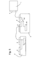
- Fig. 5 illustrates a second embodiment of a network according to the present invention.
- Components such as the TV 1 and the VCR 2 that are identical to those of Fig. 1 have the same reference numerals; modified components are distinguished from their counterparts of Fig. 1 by adding a prime (') to their reference numerals.
- the switch 13' is exclusively manually controlled and is switchable between a first position and in which it connects the tenth pin of Scart connector 8 to microprocessor 10' of PVR 3' and a second position in which it connects the tenth pins of connectors 8, 9 and leaves the microprocessor 10' disconnected.
Landscapes
- Engineering & Computer Science (AREA)
- Multimedia (AREA)
- Signal Processing (AREA)
- Human Computer Interaction (AREA)
- Databases & Information Systems (AREA)
- Strategic Management (AREA)
- Finance (AREA)
- Business, Economics & Management (AREA)
- Two-Way Televisions, Distribution Of Moving Picture Or The Like (AREA)
- Glass Compositions (AREA)
- Selective Calling Equipment (AREA)
- Studio Circuits (AREA)
- Details Of Television Systems (AREA)
Abstract
Description
- The present invention relates to an audio/video (AV) device capable of operating in a network together with at least two other AV devices. Such a network may e.g. be formed of a television set (TV) and at least two peripheral devices such as a video cassette recorder (VCR), a personal video recorder (PVR), etc.
- TVs and video recorders as currently marketed in Europe are equipped with a so-called AV-LINK feature. AV-LINK is a type of serial data communication between a TV and a video recorder connected to it which supports functions such as program mapping from the TV tuner to the video recorder tuner, timer download or emergency recording.
- The program map of a tuner is the set of receiving frequencies assigned to each of the various channels than can be selected by a user, e.g. by pressing one of the program keys of a TV remote control. Downloading a program map from a TV means that the TV can automatically transfer all or some of these frequencies to a video recorder or any other device connected to it by AV-LINK if the program map of the TV has been changed or if such a download has been requested by the device.
- Emergency recording means that a VCR can immediately start recording a program that is currently being viewed on a TV connected to it by merely pressing an emergency button on a remote control of the TV or video recorder. If this button is pressed, the TV will issue an instruction to begin recording to the video recorder. The instruction specifies the channel to which the TV is tuned, so that when the video recorder has received the instruction, it can immediately start recording the correct program without the user having to input any information identifying this program into the video recorder.
- In case of timer download, the TV is equipped with a functionality such as the so-called EPG (electronic program guide), by which a user can input desired recording start and stop times for the video recorder and channels to be recorded into the TV. By downloading these data to the video recorder, the TV can program the video recorder timer.
- For exchanging all this control information by AV-LINK, a protocol referred to as the P50 protocol has been defined. In this protocol, two subaddresses are defined for two video recorders that may simultaneously be connected to one TV. By specifying one of these addresses when sending control information via AV-LINK, the TV can determine which of the two video recorders will take account of this control information. In this way, a single TV can control two video recorders independently from one another, provided, of course, that the TV set supports the complete P50 protocol specification.
- The problem is that current TV sets do not support the two addresses defined in the P50 protocol. Even if TV sets supporting two video recorder addresses should be developed in the near future, the problem would remain that none of the millions of TV sets that are currently being used can be operated in a network with two peripheral AV devices.
- The object of the present invention is, therefore, to provide an AV device capable of operating in a small network together with a TV set and at least one more peripheral AV device which does not require the TV to support more than one address for the peripheral devices connected to it.
- This object is achieved by an AV device having two ports for exchanging AV signals and control information with other AV, with a switch placed between said two ports for allowing or preventing transmission of control information from one of said ports to the other port.
- The switch of this device may be manually controlled by a user, i.e. by setting the switch the user can decide which of the two peripheral devices of the network is to take account of control information transmitted by the TV set.
- According to a preferred embodiment the switch may alternatively or additionally be automatically controlled by a control unit of the device of the invention based on control information received from at least one of the other devices of the network.
- Based on the type of control information received from the device connected to one of its ports or on the identity of the port where the control information is received, the control unit of the AV device of the invention is able to judge whether control information received from one of the data processing devices connected to it is intended for itself or for the other data processing device, and to process or not to process the control information accordingly.
- Preferably, the control unit is adapted to control the switch according to control information received from both ports.
- The control information exchanged via the two ports of the AV data processing device is preferably in the form of individual commands that can be distinguished by the control unit. If the control unit distinguishes such a command in control information received at a first one of said ports, it will automatically close the switch so that further control information is also transmitted to a device connected to the second port. This is particularly appropriate if the device connected to the first port is a VCR and the command is e.g. a request to send the necessary information for emergency recording. This request will thus be forwarded to a TV set connected to the second port which is able to reply to it adequately. If the emergency recording request comes from the VCR (remote control of the VCR), the PVR does not start recording as the PVR has monitored the previous communication and it is aware that the request is coming from the VCR.
- On the other hand, if a command such as a program map download command from a TV is distinguished at the second port of the device of the invention, and the switch is open, the device will preferably carry out the command and close the switch in order to enable a VCR connected to the first port also to carry out the command.
- The construction described above may also have the following advantage when the two devices are not adapted to communicate with the TV simultaneously : the device according to the invention may be adapted to provoke re-emission of the received command after having closed the switch. This may be achieved by the device of the invention not acknowledging receipt of the command, if the devices of the network are adapted to re-send a command if no acknowledgement is received, or by issuing an explicit request to re-send the command.
- When the device of the invention is in an standby state, the switch should preferably be closed, so that it will not prevent communication between other devices connected to it.
- The device of the invention is preferably a video cassette recorder or a video disc recorder.
- The invention also proposes such a device further comprising a hard disk drive to record data obtained from said AV signals.
- The invention will be described more in detail and further advantages will become apparent from the following description of embodiments given with respect to the appended drawings.
- Fig. 1
- is a block diagram of a network of AV data processing devices comprising a device according to the present invention;
- Figs. 2, 3, 4
- illustrate signalisation procedures between the devices of the network of Fig. 1; and
- Fig. 5
- illustrates a second embodiment of a network according to the present invention.
- Fig. 1 is a block diagram representing a network of three AV signal processing devices, namely a TV 1, a
conventional VCR 2 and a so-called personal video recorder orPVR 3, i.e. a video device comprising a hard disc for data storage, or a DVD recorder according to the present invention. - The TV 1 has a
Scart connector 4 for exchanging AV signals and control information with theother devices - Such a Scart connector has a plurality of pins, part of which are used for exchanging AV signals and one of which, the pin No. 10, is used for serially transmitting commands of various types between the devices of the network.
- The VCR 2 has two such Scart
connectors VCR 2 and is designed to communicate with a TV receiver. - In Fig. 1 the
connector 6 is represented as unused. In principle, another network device might be connected to it. - The PVR 3 also has two
Scart connectors PVR 3. ThePVR 3 comprises amicroprocessor 10 which controls the operation of the PVR,communicates with the TV 1of the network and monitors information received from theVCR 2. It differs from the microprocessor 7 ofVCR 2 in that it has not one but twoserial interfaces first interface 11 being connected to the tenth pin of Scartconnector 8 for exchanging control information with the TV 1, and thesecond interface 12 being connected to the tenth pin of Scartconnector 9. Thefirst interface 11 is bi-directional for receiving control information from TV 1 and sending control information there, and it is adapted to distinguish the various types of commands that might be received from the TV 1. Thesecond interface 12 might be of the same type as thefirst interface 11, but preferably, it is simpler in structure and is only for receiving, but not for sending information. It need not even be able to distinguish between various types of commands; for the purposes of the present invention it is quite sufficient that thesecond interface 12 is able to detect the presence of a command in the signal it receives from theVCR 2. - A
switch 13 for connecting the tenth pins ofconnectors microprocessor 10. In a STANDBY state of thePVR 3, theswitch 13 is closed, so that all control information sent the TV 1 will be received by theVCR 2, and vice versa, as if thePVR 3 were not present. - Alternatively, the
microprocessor 10 could monitor the signals from theVCR 2 via the first interface 11 (instead of thesecond interface 12 which is then not needed). In this case,switch 13 is controlled bymicroprocessor 10 to be closed when monitoring signals from the VCR2. - Figs. 2, 3 and 4 show examples of how the exchange of control information between the
VCR 2, thePVR 3 and the TV 1 is realized. - The default position of
switch 13 is open. - In Fig. 2, it is assumed that a user has pressed an emergency recording button of the TV 1, and thus in a first step S1 the TV 1 outputs an emergency recording command specifying the channel to which the TV 1 is currently tuned. Since the
switch 13 is open, the command is not received by theVCR 2, but only by thefirst interface 11 ofPVR 3. Themicroprocessor 10 recognizes that the received command is an emergency recording command. If such a command is received, themicroprocessor 10 keeps theswitch 13 open, has an acknowledgment of the command transmitted to the TV 1 and begins to record the program identified in the command on a hard disc of thePVR 3. TheVCR 2 remains completely unaware of the dialogue between thePVR 3 and TV 1. Accordingly, if theVCR 2 happens to be in standby and a recorded cassette is inserted in it, the recordings on the cassette are protected from inadvertently being overwritten by the emergency recording. - Another type of command that can be transmitted by the TV 1 is a program map download command. In a command of this type the TV 1 transmits the frequencies to which its various channels are preset, so that later, when emergency recording command or other recording programming data are transmitted, it will only be necessary to transmit the channel number but not the receiving frequency of a program.
- The processing of such a command is shown in Fig. 3. In a first step S3, a program map download command issued by the TV 1 is received by the
PVR 3. ThePVR 3 then registers the frequencies specified in the map download command in its memory, and simultaneously, it closes theswitch 13 in step S4. It does not acknowledge receipt of the command to the TV 1. Optionally, in a second step S5 shown as a dashed arrow in Fig. 3, it may send a request to the TV 1 to repeat transmission of the map download command. - In any case, either due to non-receipt of an acknowledgement or due to receipt of the repeat request, the TV will re-send the map download command as indicated in step S6 of Fig. 3. Now, the command is also transmitted to the
VCR 2 and is carried out by it. TheVCR 2, in a quite conventional manner, will send an acknowledgment in step S7 if the command was received and carried out ok, or, in case of problems, it may also send a repeat request. In this way, in a single operation, the program frequencies stored in thePVR 3 and in theVCR 2 are updated. - Another type of command that may be transmitted by the TV 1 is a programming command. Many TVs provide a user interface such as EPG (electronic program guide) that enables a user to input desired channels, start and stop times of the programs to be recorded into the TV 1. Once the user has input the necessary data, the TV 1 will send a programming command. If the
PVR 3 is in standby or in a recording or reproducing state, and, hence, theswitch 13 is open, the command is received by thePVR 3 alone, similarly to the situation depicted in Fig. 2. ThePVR 3 carries out the command and acknowledges the receipt. TheVCR 2 remains unprogrammed. Usually, this will suit the needs of a user, since there is no interest in having two devices recording the same program, and in case of need, a recording can be transferred fromPVR 3 toVCR 2 at any later time by recording with theVCR 2 the video sequence reproduced from thePVR 3. However, if a user wishes to program theVCR 2, a menu of the PVR3 allows him to have EPG information transferred to theVCR 2 by having theswitch 13 closed, as previously explained for the program map download. In this way, EPG programming is applicable for both theVCR 2 and thePVR 3. - Up to this point, only commands transmitted by the TV 1 have been considered. Let us now consider a command transmitted by the
VCR 2, referring to Fig. 4. Such a command might be an emergency recording request issued by theVCR 2 if an emergency recording button of theVCR 2 is pressed by a user. Such a command from theVCR 2 is received by thesecond interface 12 of the PVR 3 (step S8). When themicroprocessor 10 recognizes that a command of any type has been received at theinterface 12, for a given period of time, it closes theswitch 13 and disables the first interface 11 (step S9). It does not acknowledge the command, so that after a short delay, the VCR2 re-sends it (S10). The re-sent command reaches the TV 1 via theswitch 13, now closed. The TV 1 generates a reply specifying the channel to be recorded instep S 11. This reply may be identical to the emergency recording command of step S1 described above. The reply is ignored by thePVR 3, since itsfirst interface 11 is still disabled, and is taken account of by theVCR 2. When the given period of time has elapsed, theswitch 13 is re-opened, and theinterface 12 is enabled again. - Fig. 5 illustrates a second embodiment of a network according to the present invention. Components such as the TV 1 and the
VCR 2 that are identical to those of Fig. 1 have the same reference numerals; modified components are distinguished from their counterparts of Fig. 1 by adding a prime (') to their reference numerals. The switch 13' is exclusively manually controlled and is switchable between a first position and in which it connects the tenth pin ofScart connector 8 to microprocessor 10' of PVR 3' and a second position in which it connects the tenth pins ofconnectors - In this way, in the first position of the switch, commands are exchanged between the TV 1 and the PVR 3'; and in the second position, between the TV 1 and the
VCR 2. In emergency recording command from the TV 1 will thus be executed either by the PVR 3' or theVCR 2, according to the position of the switch 13'. In order to update the PVR 3' and theVCR 2 by a program map command, the command must be transmitted twice, once in each position of the switch 13'.
Claims (9)
- An audio/video (AV) device (3, 3') having two ports (8, 9) for exchanging AV signals and control information with other AV devices (1, 2), characterised by a switch (13, 13') placed between said two ports (8, 9) for allowing or preventing transmission of control information from one of said ports (8, 9) to the other port.
- An AV device (3) according to claim 1, further comprising a control unit (10) for controlling said switch (13) according to a control information received from at least one of said ports (8, 9).
- An AV device (3) according to claim 2, wherein said control unit (10) controls said switch (13) according to control information received from both ports (8, 9).
- An AV device (3) according to one of the preceding claims, wherein said control unit (10) is adapted to distinguish individual commands in said control information and, in case the switch (13) is open when a command is distinguished in control information received at a first one of said ports (9), to close the switch (13).
- An AV device (3) according to one of the preceding claims, wherein the control unit (10) is adapted to distinguish individual commands in said control information and, in case the switch (13) is open when a command is distinguished in control information received at a second one of said ports (8), to decide whether to close or not to close the switch (13) depending on the type of command received.
- An AV device (3) according to claim 4 or 5, wherein the device is adapted to provoke re-emission of the received command after having closed the switch (13).
- An AV device (3) according to one of the preceding claims, wherein said two ports (8, 9) each comprise at least one first pin for transmitting AV data and at least one second pin for transmitting control information, and the switch (13) is located in a line connecting said second pins.
- An AV device (3) according to one of the preceding claims, the AV device being a video cassette recorder a video disc recorder.
- An AV device (3) according to any of the processing claims, further comprising a hard disk drive to record data obtained from said AV signals.
Priority Applications (3)
| Application Number | Priority Date | Filing Date | Title |
|---|---|---|---|
| DE60200193T DE60200193T2 (en) | 2002-04-08 | 2002-04-08 | Audi / video system working in a network |
| EP02290877A EP1353506B1 (en) | 2002-04-08 | 2002-04-08 | Networking audio/video device |
| AT02290877T ATE258736T1 (en) | 2002-04-08 | 2002-04-08 | AUDI/VIDEO SYSTEM WORKING IN A NETWORK |
Applications Claiming Priority (1)
| Application Number | Priority Date | Filing Date | Title |
|---|---|---|---|
| EP02290877A EP1353506B1 (en) | 2002-04-08 | 2002-04-08 | Networking audio/video device |
Publications (2)
| Publication Number | Publication Date |
|---|---|
| EP1353506A1 true EP1353506A1 (en) | 2003-10-15 |
| EP1353506B1 EP1353506B1 (en) | 2004-01-28 |
Family
ID=28051856
Family Applications (1)
| Application Number | Title | Priority Date | Filing Date |
|---|---|---|---|
| EP02290877A Expired - Lifetime EP1353506B1 (en) | 2002-04-08 | 2002-04-08 | Networking audio/video device |
Country Status (3)
| Country | Link |
|---|---|
| EP (1) | EP1353506B1 (en) |
| AT (1) | ATE258736T1 (en) |
| DE (1) | DE60200193T2 (en) |
Citations (3)
| Publication number | Priority date | Publication date | Assignee | Title |
|---|---|---|---|---|
| EP0565170A2 (en) * | 1992-04-08 | 1993-10-13 | Koninklijke Philips Electronics N.V. | Apparatus for use in a system for interconnecting appliances |
| EP0975161A2 (en) * | 1998-07-21 | 2000-01-26 | Victor Company Of Japan, Limited | Information reproducing apparatus, information recording/reproducing apparatus and information selectively outputting apparatus, and electronic apparatus system thereof |
| US6236694B1 (en) * | 1994-08-19 | 2001-05-22 | Thomson Licensing S.A. | Bus and interface system for consumer digital equipment |
-
2002
- 2002-04-08 DE DE60200193T patent/DE60200193T2/en not_active Expired - Lifetime
- 2002-04-08 AT AT02290877T patent/ATE258736T1/en not_active IP Right Cessation
- 2002-04-08 EP EP02290877A patent/EP1353506B1/en not_active Expired - Lifetime
Patent Citations (3)
| Publication number | Priority date | Publication date | Assignee | Title |
|---|---|---|---|---|
| EP0565170A2 (en) * | 1992-04-08 | 1993-10-13 | Koninklijke Philips Electronics N.V. | Apparatus for use in a system for interconnecting appliances |
| US6236694B1 (en) * | 1994-08-19 | 2001-05-22 | Thomson Licensing S.A. | Bus and interface system for consumer digital equipment |
| EP0975161A2 (en) * | 1998-07-21 | 2000-01-26 | Victor Company Of Japan, Limited | Information reproducing apparatus, information recording/reproducing apparatus and information selectively outputting apparatus, and electronic apparatus system thereof |
Also Published As
| Publication number | Publication date |
|---|---|
| ATE258736T1 (en) | 2004-02-15 |
| DE60200193D1 (en) | 2004-03-04 |
| DE60200193T2 (en) | 2004-11-25 |
| EP1353506B1 (en) | 2004-01-28 |
Similar Documents
| Publication | Publication Date | Title |
|---|---|---|
| US7924168B2 (en) | Remote control system, remote commander and remote control method, apparatus to be remotely controlled, and computer system | |
| US7688391B2 (en) | Controller for remotely controlling two or more external devices | |
| JP4386509B2 (en) | Entertainment system and method for controlling entertainment system | |
| JP3852892B2 (en) | Network control system | |
| US7839298B2 (en) | System and method for universal remote control | |
| US7046161B2 (en) | System and method for automatically setting up a universal remote control | |
| US20030189509A1 (en) | System and method for automatically setting up a universal remote control | |
| JP4660877B2 (en) | Electronic equipment system | |
| US9257037B2 (en) | System and method for automatically setting up a universal remote control | |
| JPH09270965A (en) | Network equipment | |
| US9311814B2 (en) | System and method for automatically setting up a universal remote control | |
| GB2402570A (en) | Television receiving apparatus with facility to transmit received program to second receiver | |
| JP3862431B2 (en) | Bidirectional remote control system | |
| US20180089990A1 (en) | System and method for automatically setting up a universal remote control | |
| US20050278755A1 (en) | Video data processing system with integrated high speed connection capacity | |
| EP1353506B1 (en) | Networking audio/video device | |
| JP4935178B2 (en) | Input device, transmission system, and transmission method | |
| EP1271939A1 (en) | A plurality of devices control system | |
| KR101018483B1 (en) | Digital instrument systems | |
| JP3593696B2 (en) | Digital video playback / recording device | |
| JP3744348B2 (en) | Digital device connected to network and method for controlling the same | |
| JP3525903B2 (en) | Digital video playback / recording device | |
| KR100626677B1 (en) | Control device for controlling operation using communication protocol and A / V composite device using the same | |
| JP3259772B2 (en) | Remote control system | |
| JP2004134851A (en) | Network device and method for controlling such network device |
Legal Events
| Date | Code | Title | Description |
|---|---|---|---|
| GRAH | Despatch of communication of intention to grant a patent |
Free format text: ORIGINAL CODE: EPIDOS IGRA |
|
| PUAI | Public reference made under article 153(3) epc to a published international application that has entered the european phase |
Free format text: ORIGINAL CODE: 0009012 |
|
| 17P | Request for examination filed |
Effective date: 20030318 |
|
| AK | Designated contracting states |
Kind code of ref document: A1 Designated state(s): AT BE CH CY DE DK ES FI FR GB GR IE IT LI LU MC NL PT SE TR |
|
| GRAS | Grant fee paid |
Free format text: ORIGINAL CODE: EPIDOSNIGR3 |
|
| GRAA | (expected) grant |
Free format text: ORIGINAL CODE: 0009210 |
|
| AK | Designated contracting states |
Kind code of ref document: B1 Designated state(s): AT BE CH CY DE DK ES FI FR GB GR IE IT LI LU MC NL PT SE TR |
|
| PG25 | Lapsed in a contracting state [announced via postgrant information from national office to epo] |
Ref country code: AT Free format text: LAPSE BECAUSE OF FAILURE TO SUBMIT A TRANSLATION OF THE DESCRIPTION OR TO PAY THE FEE WITHIN THE PRESCRIBED TIME-LIMIT Effective date: 20040128 Ref country code: TR Free format text: LAPSE BECAUSE OF FAILURE TO SUBMIT A TRANSLATION OF THE DESCRIPTION OR TO PAY THE FEE WITHIN THE PRESCRIBED TIME-LIMIT Effective date: 20040128 Ref country code: ES Free format text: LAPSE BECAUSE OF FAILURE TO SUBMIT A TRANSLATION OF THE DESCRIPTION OR TO PAY THE FEE WITHIN THE PRESCRIBED TIME-LIMIT Effective date: 20040128 Ref country code: NL Free format text: LAPSE BECAUSE OF FAILURE TO SUBMIT A TRANSLATION OF THE DESCRIPTION OR TO PAY THE FEE WITHIN THE PRESCRIBED TIME-LIMIT Effective date: 20040128 Ref country code: CY Free format text: LAPSE BECAUSE OF FAILURE TO SUBMIT A TRANSLATION OF THE DESCRIPTION OR TO PAY THE FEE WITHIN THE PRESCRIBED TIME-LIMIT Effective date: 20040128 Ref country code: CH Free format text: LAPSE BECAUSE OF FAILURE TO SUBMIT A TRANSLATION OF THE DESCRIPTION OR TO PAY THE FEE WITHIN THE PRESCRIBED TIME-LIMIT Effective date: 20040128 Ref country code: FI Free format text: LAPSE BECAUSE OF FAILURE TO SUBMIT A TRANSLATION OF THE DESCRIPTION OR TO PAY THE FEE WITHIN THE PRESCRIBED TIME-LIMIT Effective date: 20040128 Ref country code: LI Free format text: LAPSE BECAUSE OF FAILURE TO SUBMIT A TRANSLATION OF THE DESCRIPTION OR TO PAY THE FEE WITHIN THE PRESCRIBED TIME-LIMIT Effective date: 20040128 Ref country code: BE Free format text: LAPSE BECAUSE OF FAILURE TO SUBMIT A TRANSLATION OF THE DESCRIPTION OR TO PAY THE FEE WITHIN THE PRESCRIBED TIME-LIMIT Effective date: 20040128 |
|
| REG | Reference to a national code |
Ref country code: GB Ref legal event code: FG4D |
|
| REG | Reference to a national code |
Ref country code: CH Ref legal event code: EP |
|
| REG | Reference to a national code |
Ref country code: IE Ref legal event code: FG4D |
|
| REF | Corresponds to: |
Ref document number: 60200193 Country of ref document: DE Date of ref document: 20040304 Kind code of ref document: P |
|
| REG | Reference to a national code |
Ref country code: GB Ref legal event code: 746 Effective date: 20040223 |
|
| PG25 | Lapsed in a contracting state [announced via postgrant information from national office to epo] |
Ref country code: IE Free format text: LAPSE BECAUSE OF NON-PAYMENT OF DUE FEES Effective date: 20040408 Ref country code: LU Free format text: LAPSE BECAUSE OF NON-PAYMENT OF DUE FEES Effective date: 20040408 |
|
| PG25 | Lapsed in a contracting state [announced via postgrant information from national office to epo] |
Ref country code: SE Free format text: LAPSE BECAUSE OF FAILURE TO SUBMIT A TRANSLATION OF THE DESCRIPTION OR TO PAY THE FEE WITHIN THE PRESCRIBED TIME-LIMIT Effective date: 20040428 Ref country code: GR Free format text: LAPSE BECAUSE OF FAILURE TO SUBMIT A TRANSLATION OF THE DESCRIPTION OR TO PAY THE FEE WITHIN THE PRESCRIBED TIME-LIMIT Effective date: 20040428 Ref country code: DK Free format text: LAPSE BECAUSE OF FAILURE TO SUBMIT A TRANSLATION OF THE DESCRIPTION OR TO PAY THE FEE WITHIN THE PRESCRIBED TIME-LIMIT Effective date: 20040428 |
|
| PG25 | Lapsed in a contracting state [announced via postgrant information from national office to epo] |
Ref country code: MC Free format text: LAPSE BECAUSE OF NON-PAYMENT OF DUE FEES Effective date: 20040430 |
|
| NLV1 | Nl: lapsed or annulled due to failure to fulfill the requirements of art. 29p and 29m of the patents act | ||
| AKX | Designation fees paid |
Designated state(s): AT BE CH CY DE DK ES FI FR GB GR IE IT LI LU MC NL PT SE TR |
|
| REG | Reference to a national code |
Ref country code: CH Ref legal event code: PL |
|
| ET | Fr: translation filed | ||
| PLBE | No opposition filed within time limit |
Free format text: ORIGINAL CODE: 0009261 |
|
| STAA | Information on the status of an ep patent application or granted ep patent |
Free format text: STATUS: NO OPPOSITION FILED WITHIN TIME LIMIT |
|
| REG | Reference to a national code |
Ref country code: FR Ref legal event code: D6 |
|
| 26N | No opposition filed |
Effective date: 20041029 |
|
| REG | Reference to a national code |
Ref country code: IE Ref legal event code: MM4A |
|
| PG25 | Lapsed in a contracting state [announced via postgrant information from national office to epo] |
Ref country code: PT Free format text: LAPSE BECAUSE OF NON-PAYMENT OF DUE FEES Effective date: 20040628 |
|
| REG | Reference to a national code |
Ref country code: DE Ref legal event code: R082 Ref document number: 60200193 Country of ref document: DE Representative=s name: STEPHAN THIES, DE Ref country code: DE Ref legal event code: R082 Ref document number: 60200193 Country of ref document: DE Representative=s name: THIES, STEPHAN, DIPL.-PHYS., DE Ref country code: DE Ref legal event code: R082 Ref document number: 60200193 Country of ref document: DE Representative=s name: HOFSTETTER, SCHURACK & PARTNER PATENT- UND REC, DE |
|
| REG | Reference to a national code |
Ref country code: FR Ref legal event code: PLFP Year of fee payment: 15 |
|
| REG | Reference to a national code |
Ref country code: FR Ref legal event code: PLFP Year of fee payment: 16 |
|
| REG | Reference to a national code |
Ref country code: DE Ref legal event code: R082 Ref document number: 60200193 Country of ref document: DE Representative=s name: DEHNS, DE Ref country code: DE Ref legal event code: R082 Ref document number: 60200193 Country of ref document: DE Representative=s name: DEHNS PATENT AND TRADEMARK ATTORNEYS, DE Ref country code: DE Ref legal event code: R082 Ref document number: 60200193 Country of ref document: DE Representative=s name: HOFSTETTER, SCHURACK & PARTNER PATENT- UND REC, DE |
|
| REG | Reference to a national code |
Ref country code: FR Ref legal event code: PLFP Year of fee payment: 17 |
|
| REG | Reference to a national code |
Ref country code: DE Ref legal event code: R082 Ref document number: 60200193 Country of ref document: DE Representative=s name: DEHNS, DE Ref country code: DE Ref legal event code: R081 Ref document number: 60200193 Country of ref document: DE Owner name: INTERDIGITAL CE PATENT HOLDINGS SAS, FR Free format text: FORMER OWNER: THOMSON LICENSING S.A., BOULOGNE BILLANCOURT, FR Ref country code: DE Ref legal event code: R082 Ref document number: 60200193 Country of ref document: DE Representative=s name: DEHNS PATENT AND TRADEMARK ATTORNEYS, DE |
|
| REG | Reference to a national code |
Ref country code: GB Ref legal event code: 732E Free format text: REGISTERED BETWEEN 20190905 AND 20190911 |
|
| REG | Reference to a national code |
Ref country code: GB Ref legal event code: 732E Free format text: REGISTERED BETWEEN 20190912 AND 20190918 |
|
| PGFP | Annual fee paid to national office [announced via postgrant information from national office to epo] |
Ref country code: DE Payment date: 20200430 Year of fee payment: 19 Ref country code: FR Payment date: 20200429 Year of fee payment: 19 |
|
| PGFP | Annual fee paid to national office [announced via postgrant information from national office to epo] |
Ref country code: GB Payment date: 20200429 Year of fee payment: 19 Ref country code: IT Payment date: 20200424 Year of fee payment: 19 |
|
| REG | Reference to a national code |
Ref country code: DE Ref legal event code: R119 Ref document number: 60200193 Country of ref document: DE |
|
| GBPC | Gb: european patent ceased through non-payment of renewal fee |
Effective date: 20210408 |
|
| PG25 | Lapsed in a contracting state [announced via postgrant information from national office to epo] |
Ref country code: DE Free format text: LAPSE BECAUSE OF NON-PAYMENT OF DUE FEES Effective date: 20211103 Ref country code: GB Free format text: LAPSE BECAUSE OF NON-PAYMENT OF DUE FEES Effective date: 20210408 Ref country code: FR Free format text: LAPSE BECAUSE OF NON-PAYMENT OF DUE FEES Effective date: 20210430 |
|
| PG25 | Lapsed in a contracting state [announced via postgrant information from national office to epo] |
Ref country code: IT Free format text: LAPSE BECAUSE OF NON-PAYMENT OF DUE FEES Effective date: 20200408 |
|
| PG25 | Lapsed in a contracting state [announced via postgrant information from national office to epo] |
Ref country code: IT Free format text: LAPSE BECAUSE OF NON-PAYMENT OF DUE FEES Effective date: 20210408 |