EP1353487A2 - Mobile terminal - Google Patents
Mobile terminal Download PDFInfo
- Publication number
- EP1353487A2 EP1353487A2 EP03008482A EP03008482A EP1353487A2 EP 1353487 A2 EP1353487 A2 EP 1353487A2 EP 03008482 A EP03008482 A EP 03008482A EP 03008482 A EP03008482 A EP 03008482A EP 1353487 A2 EP1353487 A2 EP 1353487A2
- Authority
- EP
- European Patent Office
- Prior art keywords
- mobile terminal
- receiving space
- sub
- accordance
- main body
- Prior art date
- Legal status (The legal status is an assumption and is not a legal conclusion. Google has not performed a legal analysis and makes no representation as to the accuracy of the status listed.)
- Granted
Links
Images



Classifications
-
- H—ELECTRICITY
- H04—ELECTRIC COMMUNICATION TECHNIQUE
- H04M—TELEPHONIC COMMUNICATION
- H04M1/00—Substation equipment, e.g. for use by subscribers
- H04M1/02—Constructional features of telephone sets
- H04M1/0202—Portable telephone sets, e.g. cordless phones, mobile phones or bar type handsets
- H04M1/0206—Portable telephones comprising a plurality of mechanically joined movable body parts, e.g. hinged housings
- H04M1/0208—Portable telephones comprising a plurality of mechanically joined movable body parts, e.g. hinged housings characterized by the relative motions of the body parts
- H04M1/0225—Rotatable telephones, i.e. the body parts pivoting to an open position around an axis perpendicular to the plane they define in closed position
- H04M1/0227—Rotatable in one plane, i.e. using a one degree of freedom hinge
- H04M1/0229—The hinge comprising input and/or output user interface means
-
- H—ELECTRICITY
- H04—ELECTRIC COMMUNICATION TECHNIQUE
- H04B—TRANSMISSION
- H04B1/00—Details of transmission systems, not covered by a single one of groups H04B3/00 - H04B13/00; Details of transmission systems not characterised by the medium used for transmission
- H04B1/38—Transceivers, i.e. devices in which transmitter and receiver form a structural unit and in which at least one part is used for functions of transmitting and receiving
Definitions
- the present invention relates to a mobile terminal, in particular, which comprises a main body and a sub-body receivable within the main body.
- mobile terminals can be divided into bar, flip and folder type terminals.
- the bar type terminal has data I/O means and transmitting/receiving modules in one body housing.
- a key pad functioning as data input means is constantly exposed, potentially creating malfunction, and downsizing thereof is restricted since a predetermined distance is required between transmitting and receiving units.
- the flip type terminal comprises a body, a flip and hinge means for connecting the flip to the body.
- the body has data input/output means and transmitting/receiving modules, and the flip covers a key pad functioning as data input means to help prevent any malfunction.
- downsizing is also restricted in the flip type terminal for reasons including the need to maintain a predetermined distance is required between transmitting and receiving units.
- the folder type terminal comprises a body, a folder and hinge means for rotatably connecting the folder to the body so that the folder is rotated to open the folder type terminal.
- the body has a key pad and a transmitting unit functioning as data input means
- the folder has a display unit and a receiving unit functioning as data output means.
- the folder is in close contact with the body in the standby mode to prevent any malfunction, and unfolded in the conversation mode to ensure the distance between transmitting and receiving units by a sufficient amount resultantly imparting an advantage of downsizing to the folder type terminal.
- the conventional mobile terminals are restricted to the flip and folder types in external design resultantly failing to satisfy various desires of consumers.
- attachments to mobile terminals are getting diversified according to various mobile communication services, methods for connecting the attachments to the mobile terminals are extremely restricted.
- the present invention has been made to solve the foregoing problems and it is therefore an object of the present invention to provide a mobile terminal capable of satisfying various tastes and desires of consumers while allowing various attachments to be easily connected.
- a mobile terminal comprising: a main body having a ceiling, a bottom, inner walls between the ceiling and bottom and a first receiving space surrounded by the ceiling, bottom and inner walls; a sub-body rotatable around a hinge axis which is perpendicularly provided in an upper portion of the main body, the sub-body being received in the first receiving space to close the mobile terminal and released from the first receiving space to open the mobile terminal; and a second receiving space expanded in a radial direction of the hinge axis up to a predetermined diameter to penetrate the main and sub-bodies and having connector terminals in an inner wall thereof.
- Fig. 1 is a perspective view of a mobile terminal 100 according to a preferred embodiment of the invention
- Fig. 2 is a plan view of the mobile terminal 100 shown in Fig. 1.
- the mobile terminal 100 has a main body 110, a sub-body 160 pivotably coupled to the main body 110 and a second receiving space 130 for connection of an attachment at a predetermined position.
- the main body 110 has a key pad 113 in the upper face 111 including a number of key buttons and a transmitting unit 115 in one side of the key pad 113 with a microphone which is internally mounted thereon.
- the main body 110 is further provided with a first receiving space 120 between the upper face 111 and the lower face of the main body 110, within the main body 110.
- the first receiving space 120 is surrounded by the ceiling 121, the bottom 123 opposed to the ceiling 121, an inner wall 125 provided between the ceiling 121 and the bottom 123, and a hinge axis A.
- the first receiving space 120 receives the sub-body 160 during the standby mode.
- the hinge axis A is perpendicular to the upper face 111 together with a through-hole through the hinge axis A having a predetermined diameter that defines the second receiving space 130, which penetrates the main body 110.
- a plurality of connector terminals 137 are provided in an inner wall 135 of the second receiving space 130.
- the connector terminals 137 provide electric connection to attachments of the mobile terminal 100, e.g. a camera lens assembly 190 as shown in Fig. 1.
- the camera lens assembly 190 has a configuration corresponding to the second receiving space 130, and is detachably received in the second receiving space 130 via restraining means 191 that preferably is made of soft rubber. Further, the camera lens assembly 190 preferably has terminals (not shown)on its outer periphery 193 corresponding to the connector terminals 137 on the inner wall 135 of the second receiving space 130, and is electrically connected to the mobile terminal 100 via the terminals on outer periphery 193.
- the restraining means 191 is fixed by one end to the camera lens assembly 190, and by the other end, readily fixes the camera lens assembly 190 to the second receiving space 130. Further, the restraining means 191 can be utilized not only as an ornament of the mobile terminal 100 but can be functionally configured to act as a hanger for the mobile terminal 100.
- the sub-body 160 has an LCD 163 in a sub-body upper face 161 functioning as a display unit, a receiving unit 165 internally equipped with a speaker assembly above the LCD 163 and function keys 167 of the mobile terminal 100 are typically positioned below the LCD 165.
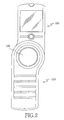
- Fig. 3 is a plan view of the mobile terminal shown in Fig. 1 in which a housing 117 of the main body 110 is partially shown in cross-section.
- the sub-body 160 has a through-hole 133 in one end thereof which aligns with the through-hole forming second receiving space.
- the through-hole 133 of the sub-body 160 is configured to surround the outer periphery of a rib 131 defining the second receiving space 130 of the main body 110, resultantly providing means for coupling the sub-body 160 to the main body 110.
- the main body 110 and the sub-body 160 are coupled to each other via the rib 131 and the through-hole 133, which are respectively provided to the main and sub-bodies 110 and 160, so that the sub-body 160 is rotatable around the hinge axis A which is perpendicular to the upper face 111 of the main body 110.
- the sub-body 160 is received in the first receiving space 120 of the main body during the standby mode, and during the conversation mode leaves the first receiving space 120 by rotating to a proper angle up to a position required for convenient conversation.
- the transmitting unit 115 and the receiving unit 165 are positioned at a distance from the hinge axis A to ensure a proper space between them which is necessary for a user in conversation.
- Fig. 5 is a perspective view of the mobile terminal 100 shown in Fig. 1 on which the camera assembly 190 is mounted as an attachment.
- the second receiving space 130 of the mobile terminal 110 provides a space to which an attachment, such as the camera lens assembly 190, can be detachably attached.
- the camera lens assembly 190 is detachably attached to the second receiving space 130 of the main body 110 via the restraining means 191 and is electrically connected via the connecter terminals 137 in the inner wall 135 of the second receiving space 130.
- the mobile terminal 100 of the invention enables the sub-body 160 to be placed within the first receiving space 120 of the main body 110 and to be rotated around the hinge axis A, which is perpendicular to the upper face 111 of the main body 110, so as to open up to the angle required for convenient conversation.
- the present invention as set forth above provides a novel design of mobile terminal beyond conventional designs of flip or folder type terminals, in which the sub-body is placed within the receiving space provided in the main body as well as rotated around the hinge axis perpendicular to the upper face of the main body so as to open to the angle necessary for convenient conversation. Further, the second receiving space is provided in the hinge axis of the sub-body to allow connection of various attachments, thereby improving the durability of the attachments. Moreover, examples of the attachments include the camera assembly as well as an MP3 player which may be selectively replaced at the convenience of the user, thereby enhance the expansibility of the mobile terminal.
Landscapes
- Engineering & Computer Science (AREA)
- Signal Processing (AREA)
- Human Computer Interaction (AREA)
- Computer Networks & Wireless Communication (AREA)
- Telephone Set Structure (AREA)
- Mobile Radio Communication Systems (AREA)
- Connector Housings Or Holding Contact Members (AREA)
Abstract
Description
Claims (11)
- A mobile terminal comprising:a main body having an internal space formed by a ceiling, a bottom and an inner wall to define a first receiving space surrounded by said ceiling, bottom and inner wall;a sub-body rotatable around a hinge axis which is perpendicular to an upper face of said main body, wherein said sub-body is received within said first receiving space to close said mobile terminal and is released from said first receiving space to open said mobile terminal; anda second receiving space of a predetermined diameter having a center at the hinge axis, wherein the second receiving space penetrates said main body and sub-body to form a through-hole therethrough.
- The mobile terminal in accordance with claim 1, wherein said main body comprises a key pad and a transmitting unit in an upper face thereof.
- The mobile terminal in accordance with claim 1 or 2, wherein said sub-body comprises a display unit and a receiving unit in an upper face thereof.
- The mobile terminal in accordance with one of claims 1 to 3, wherein said sub-body further comprises a function key.
- The mobile terminal in accordance with one of claims 1 to 4, further comprising an attachment that is detachably attached to said second receiving space.
- The mobile terminal in accordance with claim 5, wherein said attachment comprises a detachable camera and/or a camera lens assembly.
- The mobile terminal in accordance with claim 5, wherein said attachment is restrained via a restraining means.
- The mobile terminal in accordance with claim 7, wherein said restraining means is made of soft rubber.
- The mobile terminal in accordance with one of claims 1 to 8, further comprising connector terminals on an inner wall of said second receiving space.
- The mobile terminal in accordance with claim 9, wherein said connector terminals are layered along said hinge axis.
- The mobile terminal in accordance with claim 9, further comprising an attachment to be received in the second receiving space having terminals in electrical contact with the connector terminals on the inner wall of the second receiving space.
Applications Claiming Priority (2)
| Application Number | Priority Date | Filing Date | Title |
|---|---|---|---|
| KR2002020085 | 2002-04-12 | ||
| KR1020020020085A KR100575998B1 (en) | 2002-04-12 | 2002-04-12 | Portable wireless terminal |
Publications (3)
| Publication Number | Publication Date |
|---|---|
| EP1353487A2 true EP1353487A2 (en) | 2003-10-15 |
| EP1353487A3 EP1353487A3 (en) | 2003-12-10 |
| EP1353487B1 EP1353487B1 (en) | 2006-06-14 |
Family
ID=36650862
Family Applications (1)
| Application Number | Title | Priority Date | Filing Date |
|---|---|---|---|
| EP03008482A Expired - Lifetime EP1353487B1 (en) | 2002-04-12 | 2003-04-11 | Mobile terminal |
Country Status (5)
| Country | Link |
|---|---|
| US (1) | US7047053B2 (en) |
| EP (1) | EP1353487B1 (en) |
| KR (1) | KR100575998B1 (en) |
| CN (1) | CN1260941C (en) |
| DE (1) | DE60306010T2 (en) |
Cited By (2)
| Publication number | Priority date | Publication date | Assignee | Title |
|---|---|---|---|---|
| WO2004066616A1 (en) | 2003-01-21 | 2004-08-05 | Matsushita Electric Industrial Co., Ltd. | Portable device with camera |
| EP3175556B1 (en) * | 2014-07-31 | 2019-10-09 | Motorola Solutions, Inc. | Interface system for communication devices |
Families Citing this family (23)
| Publication number | Priority date | Publication date | Assignee | Title |
|---|---|---|---|---|
| JP2004312476A (en) * | 2003-04-09 | 2004-11-04 | Nec Corp | Foldable portable information terminal |
| US7454177B2 (en) * | 2003-12-08 | 2008-11-18 | Kyocera Wireless Corp. | Wireless communication device with enhanced feature set |
| KR100640380B1 (en) * | 2004-03-12 | 2006-10-30 | 삼성전자주식회사 | Swing type portable terminal |
| JP4120942B2 (en) * | 2004-07-22 | 2008-07-16 | ソニー株式会社 | Imaging device |
| CN100420359C (en) * | 2004-10-25 | 2008-09-17 | 南京Lg同创彩色显示系统有限责任公司 | Support structure of image display device |
| US7398114B2 (en) * | 2004-11-19 | 2008-07-08 | Nokia Corporation | Mobile station body comprised of stacked elements |
| KR100693561B1 (en) * | 2004-12-28 | 2007-03-14 | 주식회사 팬택 | Mobile communication terminal that can rotate two divided bodies at a certain angle in the horizontal direction |
| US7333840B2 (en) * | 2005-04-25 | 2008-02-19 | Nokia Corporation | Mobile communication terminal |
| US20070281675A1 (en) * | 2006-05-31 | 2007-12-06 | Velimir Pletikosa | Pivoting, Multi-Configuration Mobile Device |
| US8072427B2 (en) * | 2006-05-31 | 2011-12-06 | Research In Motion Limited | Pivoting, multi-configuration mobile device |
| US20070279388A1 (en) * | 2006-05-31 | 2007-12-06 | Velimir Pletikosa | Pivoting, Multi-Configuration Mobile Device |
| EP1862882A1 (en) * | 2006-05-31 | 2007-12-05 | Research In Motion Limited | Pivoting, multi-configuration mobile device |
| US7953448B2 (en) * | 2006-05-31 | 2011-05-31 | Research In Motion Limited | Keyboard for mobile device |
| TWM282435U (en) * | 2005-07-20 | 2005-12-01 | Inventec Appliances Corp | Mobile phone structure |
| KR100678135B1 (en) * | 2005-09-06 | 2007-02-02 | 삼성전자주식회사 | Handheld terminal |
| USD545802S1 (en) * | 2005-09-08 | 2007-07-03 | Samsung Electronics Co., Ltd. | Portable phone |
| KR100768857B1 (en) * | 2006-01-13 | 2007-10-22 | 엘지전자 주식회사 | Handheld terminal |
| US7580736B2 (en) * | 2007-05-29 | 2009-08-25 | Nokia Corporation | Pivot display |
| US8237283B2 (en) * | 2007-06-05 | 2012-08-07 | International Business Machines Corporation | Structure and method of reducing electromigration cracking and extrusion effects in semiconductor devices |
| US20090179859A1 (en) * | 2008-01-14 | 2009-07-16 | Shaul Wisebourt | Handheld Electronic Device Comprising A Keypad Having Multiple Character Sets Assigned Thereto, With The Character Sets Being Individually Illuminable |
| CN101600318B (en) * | 2008-06-04 | 2011-11-16 | 深圳富泰宏精密工业有限公司 | Swivel mechanism |
| US20100151902A1 (en) * | 2008-12-15 | 2010-06-17 | Nokia Corporation | Method and Apparatus for Rotating a First and/or Second Portion of an Electronic Device |
| US9042846B2 (en) * | 2013-02-27 | 2015-05-26 | Motorola Solutions, Inc. | Portable radio having accessory interface |
Family Cites Families (12)
| Publication number | Priority date | Publication date | Assignee | Title |
|---|---|---|---|---|
| KR890003205Y1 (en) * | 1986-03-04 | 1989-05-17 | 주식회사 우경제작소 | Assembly ladder hinge |
| JPH06252824A (en) | 1993-02-26 | 1994-09-09 | Sanyo Electric Co Ltd | Portable handset |
| US5485517A (en) * | 1993-12-07 | 1996-01-16 | Gray; Robert R. | Portable wireless telephone having swivel chassis |
| GB2351201B (en) | 1996-07-10 | 2001-02-07 | Motorola Inc | Communication device |
| JPH10261910A (en) * | 1997-01-16 | 1998-09-29 | Sony Corp | Portable wireless device and antenna device |
| JP2000253124A (en) | 1999-03-01 | 2000-09-14 | Matsushita Electric Ind Co Ltd | Information portable terminal with imaging function |
| JP2001054084A (en) * | 1999-08-09 | 2001-02-23 | Matsushita Electric Ind Co Ltd | Videophone equipment |
| JP2001156893A (en) | 1999-11-29 | 2001-06-08 | Nec Saitama Ltd | Display system and its method for communication apparatus |
| JP3546784B2 (en) * | 1999-12-14 | 2004-07-28 | 日本電気株式会社 | Mobile device |
| KR20010068807A (en) * | 2000-01-10 | 2001-07-23 | 윤종용 | Radiotelephone for visual communication |
| US6658272B1 (en) | 2000-04-28 | 2003-12-02 | Motorola, Inc. | Self configuring multiple element portable electronic device |
| CN2484703Y (en) | 2001-05-09 | 2002-04-03 | 周学良 | Folding-type mobile telephone |
-
2002
- 2002-04-12 KR KR1020020020085A patent/KR100575998B1/en not_active Expired - Fee Related
-
2003
- 2003-04-09 US US10/410,454 patent/US7047053B2/en not_active Expired - Fee Related
- 2003-04-10 CN CNB031102948A patent/CN1260941C/en not_active Expired - Fee Related
- 2003-04-11 DE DE60306010T patent/DE60306010T2/en not_active Expired - Lifetime
- 2003-04-11 EP EP03008482A patent/EP1353487B1/en not_active Expired - Lifetime
Cited By (3)
| Publication number | Priority date | Publication date | Assignee | Title |
|---|---|---|---|---|
| WO2004066616A1 (en) | 2003-01-21 | 2004-08-05 | Matsushita Electric Industrial Co., Ltd. | Portable device with camera |
| EP1608151A4 (en) * | 2003-01-21 | 2009-04-29 | Panasonic Corp | PORTABLE APPARATUS WITH CAMERA |
| EP3175556B1 (en) * | 2014-07-31 | 2019-10-09 | Motorola Solutions, Inc. | Interface system for communication devices |
Also Published As
| Publication number | Publication date |
|---|---|
| KR100575998B1 (en) | 2006-05-02 |
| DE60306010T2 (en) | 2006-10-05 |
| CN1260941C (en) | 2006-06-21 |
| EP1353487A3 (en) | 2003-12-10 |
| EP1353487B1 (en) | 2006-06-14 |
| US7047053B2 (en) | 2006-05-16 |
| DE60306010D1 (en) | 2006-07-27 |
| CN1452372A (en) | 2003-10-29 |
| KR20030081725A (en) | 2003-10-22 |
| US20040204203A1 (en) | 2004-10-14 |
Similar Documents
| Publication | Publication Date | Title |
|---|---|---|
| EP1353487A2 (en) | Mobile terminal | |
| KR100417248B1 (en) | Slide type mobile phone using slide module | |
| EP1420567A2 (en) | Portable terminal capable of providing stereo sound | |
| KR100663459B1 (en) | Replaceable sliding cover device of folder in clamshell mobile terminal | |
| KR20050037054A (en) | Portable terminal and swing hinge module thereof | |
| JPH04273744A (en) | mobile phone | |
| KR20120012607A (en) | Portable terminal with detachable Bluetooth headset | |
| KR100651410B1 (en) | 2-way clamshell terminal | |
| KR100640452B1 (en) | Portable communication devices | |
| KR100663486B1 (en) | Interface connector cover switchgear of mobile terminal | |
| US7092680B2 (en) | Replaceable sub-housing and interchangeable mobile telephone terminal using the same to be used both as flip-type terminal and bar-type terminal | |
| KR101429277B1 (en) | Portable electronic devices with multifunction covers | |
| KR100918036B1 (en) | Handheld terminal with internal dual LCD | |
| KR20040042477A (en) | Cellular Phone With Stereo Sound Function | |
| KR100557166B1 (en) | Portable wireless terminal | |
| JP3298496B2 (en) | Mobile phone | |
| KR100663490B1 (en) | Speaker device of mobile terminal using antenna mounting space | |
| KR100819277B1 (en) | Portable wireless terminal | |
| JP3692584B2 (en) | Portable communication device | |
| KR100350503B1 (en) | Folding-type portable radiotelephone with neckwear module phone | |
| KR200241098Y1 (en) | A mobile phone | |
| KR100442659B1 (en) | Portable phone with stereo sound | |
| KR200184591Y1 (en) | Mobile phone of headphone type | |
| EP1484900A1 (en) | Housing assembly for portable electronic device | |
| KR100311537B1 (en) | Union Stucture Mini Phone Of Mouse For Computer |
Legal Events
| Date | Code | Title | Description |
|---|---|---|---|
| PUAI | Public reference made under article 153(3) epc to a published international application that has entered the european phase |
Free format text: ORIGINAL CODE: 0009012 |
|
| 17P | Request for examination filed |
Effective date: 20030411 |
|
| AK | Designated contracting states |
Kind code of ref document: A2 Designated state(s): AT BE BG CH CY CZ DE DK EE ES FI FR GB GR HU IE IT LI LU MC NL PT RO SE SI SK TR |
|
| AX | Request for extension of the european patent |
Extension state: AL LT LV MK |
|
| PUAL | Search report despatched |
Free format text: ORIGINAL CODE: 0009013 |
|
| AK | Designated contracting states |
Kind code of ref document: A3 Designated state(s): AT BE BG CH CY CZ DE DK EE ES FI FR GB GR HU IE IT LI LU MC NL PT RO SE SI SK TR |
|
| AX | Request for extension of the european patent |
Extension state: AL LT LV MK |
|
| AKX | Designation fees paid |
Designated state(s): DE FR GB |
|
| 17Q | First examination report despatched |
Effective date: 20050610 |
|
| GRAP | Despatch of communication of intention to grant a patent |
Free format text: ORIGINAL CODE: EPIDOSNIGR1 |
|
| RAP1 | Party data changed (applicant data changed or rights of an application transferred) |
Owner name: SAMSUNG ELECTRONICS CO., LTD. |
|
| GRAS | Grant fee paid |
Free format text: ORIGINAL CODE: EPIDOSNIGR3 |
|
| GRAA | (expected) grant |
Free format text: ORIGINAL CODE: 0009210 |
|
| AK | Designated contracting states |
Kind code of ref document: B1 Designated state(s): DE FR GB |
|
| REG | Reference to a national code |
Ref country code: GB Ref legal event code: FG4D |
|
| REF | Corresponds to: |
Ref document number: 60306010 Country of ref document: DE Date of ref document: 20060727 Kind code of ref document: P |
|
| ET | Fr: translation filed | ||
| PLBE | No opposition filed within time limit |
Free format text: ORIGINAL CODE: 0009261 |
|
| STAA | Information on the status of an ep patent application or granted ep patent |
Free format text: STATUS: NO OPPOSITION FILED WITHIN TIME LIMIT |
|
| 26N | No opposition filed |
Effective date: 20070315 |
|
| REG | Reference to a national code |
Ref country code: FR Ref legal event code: PLFP Year of fee payment: 14 |
|
| PGFP | Annual fee paid to national office [announced via postgrant information from national office to epo] |
Ref country code: GB Payment date: 20160311 Year of fee payment: 14 |
|
| PGFP | Annual fee paid to national office [announced via postgrant information from national office to epo] |
Ref country code: DE Payment date: 20160421 Year of fee payment: 14 |
|
| PGFP | Annual fee paid to national office [announced via postgrant information from national office to epo] |
Ref country code: FR Payment date: 20160415 Year of fee payment: 14 |
|
| REG | Reference to a national code |
Ref country code: DE Ref legal event code: R119 Ref document number: 60306010 Country of ref document: DE |
|
| GBPC | Gb: european patent ceased through non-payment of renewal fee |
Effective date: 20170411 |
|
| REG | Reference to a national code |
Ref country code: FR Ref legal event code: ST Effective date: 20171229 |
|
| PG25 | Lapsed in a contracting state [announced via postgrant information from national office to epo] |
Ref country code: FR Free format text: LAPSE BECAUSE OF NON-PAYMENT OF DUE FEES Effective date: 20170502 Ref country code: DE Free format text: LAPSE BECAUSE OF NON-PAYMENT OF DUE FEES Effective date: 20171103 |
|
| PG25 | Lapsed in a contracting state [announced via postgrant information from national office to epo] |
Ref country code: GB Free format text: LAPSE BECAUSE OF NON-PAYMENT OF DUE FEES Effective date: 20170411 |