EP1353474A2 - Indicating occurrence of protocol events - Google Patents
Indicating occurrence of protocol events Download PDFInfo
- Publication number
- EP1353474A2 EP1353474A2 EP03251491A EP03251491A EP1353474A2 EP 1353474 A2 EP1353474 A2 EP 1353474A2 EP 03251491 A EP03251491 A EP 03251491A EP 03251491 A EP03251491 A EP 03251491A EP 1353474 A2 EP1353474 A2 EP 1353474A2
- Authority
- EP
- European Patent Office
- Prior art keywords
- protocol
- trigger signal
- implementation
- performance
- message
- Prior art date
- Legal status (The legal status is an assumption and is not a legal conclusion. Google has not performed a legal analysis and makes no representation as to the accuracy of the status listed.)
- Withdrawn
Links
Images



Classifications
-
- H—ELECTRICITY
- H04—ELECTRIC COMMUNICATION TECHNIQUE
- H04L—TRANSMISSION OF DIGITAL INFORMATION, e.g. TELEGRAPHIC COMMUNICATION
- H04L69/00—Network arrangements, protocols or services independent of the application payload and not provided for in the other groups of this subclass
- H04L69/03—Protocol definition or specification
-
- H—ELECTRICITY
- H04—ELECTRIC COMMUNICATION TECHNIQUE
- H04L—TRANSMISSION OF DIGITAL INFORMATION, e.g. TELEGRAPHIC COMMUNICATION
- H04L41/00—Arrangements for maintenance, administration or management of data switching networks, e.g. of packet switching networks
- H04L41/14—Network analysis or design
- H04L41/147—Network analysis or design for predicting network behaviour
-
- H—ELECTRICITY
- H04—ELECTRIC COMMUNICATION TECHNIQUE
- H04L—TRANSMISSION OF DIGITAL INFORMATION, e.g. TELEGRAPHIC COMMUNICATION
- H04L43/00—Arrangements for monitoring or testing data switching networks
- H04L43/50—Testing arrangements
Definitions
- This invention relates to indicating occurrence of events which occur in conformity with a predetermined protocol.
- the invention may be used, for example, for generation of trigger signals indicative of events occurring, or predicted to occur, on the basis of information from layers of a protocol stack other than the physical layer.
- the detection or prediction of a protocol event and the initiation of the trigger signal may be implemented in software.
- a trigger signal is a common feature in instrumentation, typically using transistor-transistor logic (TTL) signals at defined voltage levels, having either a positive- or negative-going edge and a defined pulse width.
- TTL transistor-transistor logic
- Such a signal can be used to initiate a user-defined behaviour (e.g. taking a measurement of a parameter) in the equipment or device to which the trigger signal is supplied.
- Testing such devices can present severe challenges, especially when a malfunction involves failure of different devices to inter-operate correctly. It is an object of this invention to provide methods and apparatus for facilitating such testing.
- a method of providing an indication relating to occurrence of an event in conformity with a predetermined protocol comprising:
- the selected step associated with a requirement for a trigger signal may be any of a wide variety of actions and features incorporated in a protocol, such as sending of a message, receipt of a message, a transition within a state machine which is maintained during operation of a protocol, or expiry of a timer.
- apparatus for providing an indication relating to occurrence of an event in conformity with a predetermined protocol comprising:
- a protocol stack is a well-defined concept which is used extensively in the conception, design and implementation of communications systems. Referring to Figure 1, such a stack consists of a series of protocol layers, each of which has its own role.
- a layer can communicate with its peer layer (e.g. in another device) by passing information down through the layers of the protocol stack and over a physical interface, which comprises layer one, to the other device. The information will then travel up through the layers of the protocol stack in the second device, to reach the peer layer.
- the International Standards Organisation has defined a seven-layer model, shown in Figure 2, for protocols for network communications. This model is also known as the Open Systems Interconnection (OSI) model. As noted above, the lowermost physical interface or layer is responsible for physical transmission of signals between the devices to convey information, as well as for the encoding/decoding of those signals. The information content, along with instructions or requests for peer layers to transmit information, are provided by the six higher layers.
- OSI Open Systems Interconnection
- a protocol may be implemented by using a general-purpose processor, or a more dedicated digital signal processor, operating under control of software program instructions stored in associated memory.
- the program instructions specify the sequence of operations required to perform the various steps embodied in each layer of the protocol.
- the invention involves generation of trigger signals, for example to co-ordinate operation of test and monitoring equipment.
- a trigger signal is required to comply with predefined voltage level and timing characteristics.
- Generation of such a trigger signal for example a TTL signal having a defined voltage with a positive- or negative-going edge, is in itself a standard capability provided in commercially-available integrated-circuit chips.
- the chip is arranged to read in a repetitive cycle the contents of a sequence of memory locations that each contain either a binary 1 or a binary 0 value. The value stored in a memory location is used to determine whether the output from the chip is a high or low voltage level for brief, fixed time interval.
- the value in the next memory location is inspected, to determine the output signal level for the following interval.
- the majority of memory locations are configured to contain one value, and an occasional trigger signal is produced by the presence of the other value in a small block of adjacent memory locations.
- the position of the block within the overall sequence of locations, and the timing of reading of the first location in the sequence, enable control of the trigger signal to occur at a desired instant in time.
- a device that can provide this functionality is referred to hereinafter as a 'trigger chip'.
- FIG. 3 shows a trigger chip 10 and a processor 12 that implements the physical layer 14 and higher layers 16 of a protocol, interacting to provide an apparatus in accordance with this invention.
- the processor 12 is coupled to an external connector 18 for output of physical layer signals. This external connector provides the physical interface for communication with a peer device, either wired or wirelessly. Both the physical layer and the higher layers of protocol are arranged to interact with the trigger chip 10.
- the processor 12 can supply signals to the trigger chip 10 in accordance with instructions in its controlling software program.
- references hereinafter to communication between the processor 12 and the trigger chip 10 may be expressed in terms of communication with the protocol layers implemented by the processor when in operation.
- a physical layer typically embodies a concept of absolute time, that is a time reference by which the operation of the entire communications link, including the higher protocol layers at both ends of the link, is co-ordinated.
- this capability is used to enable the physical layer 14 to communicate with the trigger chip 10 and produce trigger signals at defined instants in time on an external trigger output 20.
- the higher layers 16 may also communicate with the trigger chip 10 directly to produce trigger signals.
- higher layer events that require an association with absolute time typically route their requests for a trigger signal through the physical layer 14.
- a 'protocol event' as referred to herein is something that occurs in the interaction of one of the higher layers 16 with a peer layer or its adjacent layers in the protocol stack implemented in another device.
- Such a protocol event while initiated by one of the higher layers 16, may involve information passing to a lower layer, including the physical layer 14 - for example the transmission of a message.
- the protocol event may consist of a significant occurrence in the implementation of a particular layer - for example, the start or end of a procedure or the expiry of a timer. It may consist of a combination of one or more protocol events occurring in different layers. It may consist of the reception of a particular message at a protocol layer, or a message containing a particular parameter or parameter value. Another type of protocol event is predictive.
- one of the higher layers 16 expects certain behaviour from a peer layer in another device to occur, typically at a certain point in time. Even if this expected behaviour does not actually occur, owing to malfunction of the peer device, its predicted occurrence and timing in accordance with the protocol still constitute a protocol event.
- Protocol messages are sent back and forth between the peer protocol stacks (e.g. phone protocol stack and test instrument protocol stack). Some of these messages can cause changes to the physical transmission (frequency, power, timing). It is challenging in this situation to relate together the following occurrences which are separated in time and in different devices:
- a parameter or indicator (flag) is added to it which the physical layer examines. If the added parameter is set, the physical layer 14 configures the trigger chip 10 such that a trigger signal is produced at the same time as the message is transmitted on the external connector 18.
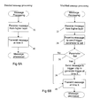
- Figure 5a shows the standard method of sending a message from a higher protocol layer 16.
- a message is constructed at step 26 and passed to a lower layer at step 30.
- Figure 5b shows how this operation is modified in order to implement the invention.
- steps 22 and 24 e.g. by examining a flag or indicator controlled via a user interface
- the message construction or format is modified to include an extra parameter to indicate whether or not the trigger should be generated when the message is transmitted. This extra parameter is set appropriately at one of steps 27 and 29, depending on the outcome of the test at step 24, before the message is passed to the lower layer at step 30.
- the physical layer 14 is modified in a complementary manner.
- a message is received by the physical layer at step 32, and transmitted at time X (step 40).
- the modified operation shown in Figure 6b, checks the extra parameter at steps 34 and 36 when the message is received. If the parameter is set, the physical layer sends a message to the trigger chip 10 at step 38, requesting a trigger signal to be generated at time X. The message itself is then transmitted at step 40 as before, also at time X.
- the relevant higher layer 16 knows when in time the specific peer behaviour of interest is expected to occur. However the higher layer itself typically does not possess the appropriate chronometer functionality, so it sends to the physical layer 14 an internal special-purpose message, added to the protocol for this purpose, to instruct the trigger chip 10 to create a trigger signal at this particular time.
- the higher layer 16 in the test equipment instructs (sends a message to) the peer layer in the mobile device under test to change to a new radio frequency.
- the higher layer 16 in the test equipment expects (predicts) this change to happen upon occurrence of a particular subsequent transmission frame in the mobile device's transmitted signal, say within one GSM radio frame (4.6ms); accordingly it sends a request to the physical layer 14 in the test equipment protocol stack to create a trigger signal at this time.
- This example relates to occurrence of a previously-specified higher layer protocol event.
- the higher layer 16 communicates directly (rather than via the physical layer 14) with the trigger chip 10 which then creates a trigger signal.
- a specific example of this is successful reception by a higher layer 16 of a message from a peer layer in another device, as shown in Figure 8.
- the trigger signal in this case is simply a confirmation that the event has occurred, rather than a signal from which absolute timing can be derived.
- there may be latency in the protocol stack due to re-transmissions or message reassembly. This latency may render timing information of limited utility.
Landscapes
- Engineering & Computer Science (AREA)
- Computer Networks & Wireless Communication (AREA)
- Signal Processing (AREA)
- Computer Security & Cryptography (AREA)
- Maintenance And Management Of Digital Transmission (AREA)
- Communication Control (AREA)
- Bus Control (AREA)
- Computer And Data Communications (AREA)
Abstract
Description
- Figure 1
- illustrates the concept of a protocol stack;
- Figure 2
- shows a standard 7-layer model of a protocol stack;
- Figure 3
- is a block schematic diagram of functional blocks for generating a trigger signal in accordance with this invention;
- Figure 4
- is a message sequence chart illustrating physical transmission of a protocol message from a higher protocol layer;
- Figures 5A and
- 5B show respectively a normal method of sending a message to a lower protocol layer, and a modified method in accordance with this invention;
- Figures 6A and 6B
- show respectively a normal method of processing a message received from a higher protocol layer, and a modified method in accordance with this invention;
- Figure 7
- is a message sequence chart illustrating prediction of when expected behaviour in a peer protocol layer should occur; and
- Figure 8
- is a message sequence chart illustrating asynchronous indication that an event has occurred.
- A higher layer decision to send a message.
- Physical transmission of that message over the air interface.
- Reception of that message in the peer stack.
- An expected response from the peer stack.
Claims (6)
- A method of providing an indication relating to occurrence of an event in conformity with a predetermined protocol, comprising:selecting a step involved in implementation of the protocol;recording association with the selected step of a requirement for a trigger signal;monitoring performance of steps comprising implementation of the protocol;detecting a condition related to performance of the selected step; andgenerating a trigger signal, in addition to any signal generated as part of implementation of the protocol, to indicate occurrence of the detected condition.
- The method of claim 1, wherein detection of the condition related to performance of the selected step comprises detection of performance of the step.
- The method of claim 1, wherein detection of the condition related to performance of the selected step comprises detection that a time interval has elapsed during which the selected step could be expected to have been performed.
- The method of any one of the preceding claims, wherein the selected step comprises generation of an output, such as a protocol message.
- The method of any one of claims 1 to 4, wherein the selected step comprises receipt of an input, such as a protocol message.
- Apparatus for providing an indication relating to occurrence of an event in conformity with a predetermined protocol, comprising:a store for recording association of a requirement for a trigger signal with a selected step involved in implementation of the protocol;a monitor for monitoring performance of steps comprising implementation of the protocol;a detector for detecting a condition related to performance of the selected step; anda trigger signal generator for generating a trigger signal, in addition to any signal generated as part of implementation of the protocol, to indicate occurrence of the detected condition.
Applications Claiming Priority (2)
| Application Number | Priority Date | Filing Date | Title |
|---|---|---|---|
| US105791 | 2002-03-26 | ||
| US10/105,791 US20030185216A1 (en) | 2002-03-26 | 2002-03-26 | Indicating occurrence of protocol events |
Publications (2)
| Publication Number | Publication Date |
|---|---|
| EP1353474A2 true EP1353474A2 (en) | 2003-10-15 |
| EP1353474A3 EP1353474A3 (en) | 2004-07-28 |
Family
ID=28452448
Family Applications (1)
| Application Number | Title | Priority Date | Filing Date |
|---|---|---|---|
| EP03251491A Withdrawn EP1353474A3 (en) | 2002-03-26 | 2003-03-12 | Indicating occurrence of protocol events |
Country Status (3)
| Country | Link |
|---|---|
| US (1) | US20030185216A1 (en) |
| EP (1) | EP1353474A3 (en) |
| JP (1) | JP2003333119A (en) |
Families Citing this family (9)
| Publication number | Priority date | Publication date | Assignee | Title |
|---|---|---|---|---|
| US7457881B2 (en) * | 2003-08-14 | 2008-11-25 | Hewlett-Packard Development Company, L.P. | Method and apparatus for sending data from one protocol layer to another |
| US8130633B2 (en) * | 2004-10-22 | 2012-03-06 | Research In Motion Limited | Method for transferring data in a wireless network |
| US8768343B2 (en) | 2006-03-31 | 2014-07-01 | Zebra Enterprise Solutions Corp | Wireless local area network receiver and associated method |
| US8892065B2 (en) * | 2006-04-26 | 2014-11-18 | Zebra Enterprise Solutions Corp. | Method, apparatus, and computer program product for wireless signal storage with signal recognition detection triggering |
| US9362976B2 (en) | 2006-04-26 | 2016-06-07 | Zih Corp. | Wireless local area network system and receiver adapted for use thereof and associated method |
| CN103220706B (en) * | 2009-11-25 | 2016-11-23 | 中国移动通信集团广西有限公司 | Obtain the method for terminal communication event information, system and equipment |
| US20110320179A1 (en) * | 2010-06-28 | 2011-12-29 | International Business Machines Corporation | Process monitoring |
| US10802108B2 (en) | 2014-07-31 | 2020-10-13 | Symbol Technologies, Llc | Two pass detection technique for non-echo pulsed ranging |
| US9674722B1 (en) * | 2016-09-01 | 2017-06-06 | Litepoint Corporation | Method for testing a GSM (global system for mobile communications) handset with reduced signaling requirements |
Family Cites Families (8)
| Publication number | Priority date | Publication date | Assignee | Title |
|---|---|---|---|---|
| US4972139A (en) * | 1989-05-12 | 1990-11-20 | Tektronix, Inc. | Method for increasing the resolution of measurements taken using a counter-timer |
| US5850388A (en) * | 1996-08-02 | 1998-12-15 | Wandel & Goltermann Technologies, Inc. | Protocol analyzer for monitoring digital transmission networks |
| EP0853399B1 (en) * | 1997-01-13 | 2005-08-03 | Agilent Technologies, Inc. (a Delaware corporation) | Report stream data rate regulation |
| US6654349B1 (en) * | 1999-08-17 | 2003-11-25 | Advanced Micro Devices, Inc. | Real time automated checking mechanism for a bus protocol on an integrated bus system |
| AU2001232983A1 (en) * | 2000-01-26 | 2001-08-07 | Invertix Corporation | Method and apparatus for sharing mobile user event information between wireless networks and fixed ip networks |
| JP2002026877A (en) * | 2000-06-07 | 2002-01-25 | Agilent Technol Inc | Block error rate measurement method |
| US6839344B1 (en) * | 2000-12-19 | 2005-01-04 | Nortel Networks Limited | Transport mechanism for ISDN backhaul over IP |
| US20020156886A1 (en) * | 2001-04-23 | 2002-10-24 | Krieski William George | Protocol monitor |
-
2002
- 2002-03-26 US US10/105,791 patent/US20030185216A1/en not_active Abandoned
-
2003
- 2003-03-12 EP EP03251491A patent/EP1353474A3/en not_active Withdrawn
- 2003-03-19 JP JP2003075569A patent/JP2003333119A/en active Pending
Also Published As
| Publication number | Publication date |
|---|---|
| JP2003333119A (en) | 2003-11-21 |
| US20030185216A1 (en) | 2003-10-02 |
| EP1353474A3 (en) | 2004-07-28 |
Similar Documents
| Publication | Publication Date | Title |
|---|---|---|
| US6862699B2 (en) | Apparatus for testing functions of communication apparatus | |
| JP2014504053A (en) | Achieving improved test efficiency using acknowledgment signal suppression | |
| US20080195920A1 (en) | Self-test structure and method of testing a digital interface | |
| EP0806855A2 (en) | Automatic configuration of protocol parameters in protocol layers for public area networks | |
| US20030185216A1 (en) | Indicating occurrence of protocol events | |
| KR20010054212A (en) | An apparatus and method of performance analysis unit for CDMA mobile radio system supporting multimedia service | |
| CN114727352B (en) | Information transmission method, device, storage medium and electronic equipment | |
| US20050119020A1 (en) | Automatically information-collecting method and information-collecting system | |
| JP2005252825A (en) | Diversity control method and wireless communication apparatus | |
| JP5287476B2 (en) | Radio terminal reception sensitivity measurement system | |
| JP2002016544A (en) | Mobile phone, mobile phone failure determination method and failure determination device | |
| JP3966081B2 (en) | Communication control system and communication system | |
| JPH07273746A (en) | Terminal test equipment | |
| Schwarz et al. | A communication observer for monitoring the safety integrity level in real-time | |
| CN114039895B (en) | Method and device for testing data transmission rate | |
| KR100528410B1 (en) | Synchronization Signal and Packet Status Information Control Device in High Level Data Link Control Communication | |
| KR100417372B1 (en) | Apparatus for testing taxi port in exchange | |
| KR100822857B1 (en) | Wireless protocol monitor device and operation method in wireless communication control station | |
| JP2005051645A (en) | Radio communication type data input terminal, and program of its host computer | |
| US7496792B2 (en) | Repeat digital message transmission between a microprocessor monitoring circuit and an analyzing tool | |
| KR100694350B1 (en) | PPU data processing device of mobile communication terminal and processing method thereof | |
| KR100319480B1 (en) | Radio communication method between meter and hand terminal in the hand terminal | |
| KR100378680B1 (en) | Method for carrying out remote line loopback | |
| JPH11112606A (en) | Communication failure handling method and communication device | |
| KR100372914B1 (en) | Method and apparatus for monitoring an intelligent network application protocol in a full electronic switching system |
Legal Events
| Date | Code | Title | Description |
|---|---|---|---|
| PUAI | Public reference made under article 153(3) epc to a published international application that has entered the european phase |
Free format text: ORIGINAL CODE: 0009012 |
|
| AK | Designated contracting states |
Kind code of ref document: A2 Designated state(s): AT BE BG CH CY CZ DE DK EE ES FI FR GB GR HU IE IT LI LU MC NL PT RO SE SI SK TR |
|
| AX | Request for extension of the european patent |
Extension state: AL LT LV MK |
|
| PUAL | Search report despatched |
Free format text: ORIGINAL CODE: 0009013 |
|
| AK | Designated contracting states |
Kind code of ref document: A3 Designated state(s): AT BE BG CH CY CZ DE DK EE ES FI FR GB GR HU IE IT LI LU MC NL PT RO SE SI SK TR |
|
| AX | Request for extension of the european patent |
Extension state: AL LT LV MK |
|
| 17P | Request for examination filed |
Effective date: 20050128 |
|
| AKX | Designation fees paid |
Designated state(s): DE FR GB |
|
| 17Q | First examination report despatched |
Effective date: 20050317 |
|
| STAA | Information on the status of an ep patent application or granted ep patent |
Free format text: STATUS: THE APPLICATION IS DEEMED TO BE WITHDRAWN |
|
| 18D | Application deemed to be withdrawn |
Effective date: 20050928 |