EP1353358A2 - Parabolic reflector lamp assembly with a light absorbing layer on the neck cavity - Google Patents
Parabolic reflector lamp assembly with a light absorbing layer on the neck cavity Download PDFInfo
- Publication number
- EP1353358A2 EP1353358A2 EP03005531A EP03005531A EP1353358A2 EP 1353358 A2 EP1353358 A2 EP 1353358A2 EP 03005531 A EP03005531 A EP 03005531A EP 03005531 A EP03005531 A EP 03005531A EP 1353358 A2 EP1353358 A2 EP 1353358A2
- Authority
- EP
- European Patent Office
- Prior art keywords
- lamp
- neck
- light
- reflector
- source
- Prior art date
- Legal status (The legal status is an assumption and is not a legal conclusion. Google has not performed a legal analysis and makes no representation as to the accuracy of the status listed.)
- Withdrawn
Links
Images


Classifications
-
- H—ELECTRICITY
- H01—ELECTRIC ELEMENTS
- H01J—ELECTRIC DISCHARGE TUBES OR DISCHARGE LAMPS
- H01J61/00—Gas-discharge or vapour-discharge lamps
- H01J61/02—Details
- H01J61/30—Vessels; Containers
-
- H—ELECTRICITY
- H01—ELECTRIC ELEMENTS
- H01J—ELECTRIC DISCHARGE TUBES OR DISCHARGE LAMPS
- H01J61/00—Gas-discharge or vapour-discharge lamps
- H01J61/02—Details
- H01J61/30—Vessels; Containers
- H01J61/35—Vessels; Containers provided with coatings on the walls thereof; Selection of materials for the coatings
-
- H—ELECTRICITY
- H01—ELECTRIC ELEMENTS
- H01J—ELECTRIC DISCHARGE TUBES OR DISCHARGE LAMPS
- H01J61/00—Gas-discharge or vapour-discharge lamps
- H01J61/02—Details
- H01J61/30—Vessels; Containers
- H01J61/34—Double-wall vessels or containers
-
- H—ELECTRICITY
- H01—ELECTRIC ELEMENTS
- H01J—ELECTRIC DISCHARGE TUBES OR DISCHARGE LAMPS
- H01J61/00—Gas-discharge or vapour-discharge lamps
- H01J61/02—Details
- H01J61/12—Selection of substances for gas fillings; Specified operating pressure or temperature
- H01J61/125—Selection of substances for gas fillings; Specified operating pressure or temperature having an halogenide as principal component
-
- H—ELECTRICITY
- H01—ELECTRIC ELEMENTS
- H01J—ELECTRIC DISCHARGE TUBES OR DISCHARGE LAMPS
- H01J61/00—Gas-discharge or vapour-discharge lamps
- H01J61/02—Details
- H01J61/52—Cooling arrangements; Heating arrangements; Means for circulating gas or vapour within the discharge space
- H01J61/523—Heating or cooling particular parts of the lamp
-
- H—ELECTRICITY
- H01—ELECTRIC ELEMENTS
- H01J—ELECTRIC DISCHARGE TUBES OR DISCHARGE LAMPS
- H01J61/00—Gas-discharge or vapour-discharge lamps
- H01J61/82—Lamps with high-pressure unconstricted discharge having a cold pressure > 400 Torr
- H01J61/827—Metal halide arc lamps
Definitions
- the invention relates to electric lamps and particularly to electric lamps enclosed in a reflector. More particularly the invention is concerned with a reflector lamp (PAR) with a ceramic metal halide lamp capsule with a reduced lamp capsule seal temperature.
- PAR reflector lamp
- Ceramic lamp envelopes with modem metal halide seals have developed a new class of metal halide lamps (Geven et. al. in US 5,424,609 and by Carleton et. al. in J. Ill. Eng. Soc. P139-145, Winter 1996 (Proc. Of IESNA Annual Conference)). These lamps contain metal halide fill chemistries, and two electrodes. A high voltage pulse between the electrodes is used to ignite the lamp. Normal current and voltage is then applied through the electrodes to excite the enclosed gas and fill materials to a plasma state.
- Typical fills include rare earth halides with various other additives including thallium halide and calcium halide, in addition to an inert starting gas such as argon or xenon.
- the ceramic arc tube is often jacketed in another envelope, called an outer jacket, to protect the inner arc tube from the air.
- an outer jacket to protect the inner arc tube from the air.
- Many of the lamp parts especially niobium electrical in-leads, oxidize rapidly if exposed to air at the lamp operating temperatures, causing the lamp to fail.
- These outer jackets are usually thermally isolated from the arc tube by construction and contain a vacuum or are filled with a partial pressure of an inert gas and a getter material, for example a zirconium and aluminum compound, to getter oxygen and hydrogen.
- the inner arc tube and outer jacket are mounted inside a parabolic reflector (PAR or PAR lamp) to gather and direct the generated light from the lamp in a useful beam pattern.
- This can be a flood or a spot beam for illumination of interior surfaces or building facades in exterior applications.
- Such lamps with halogen light sources are also commonly used for illuminating merchandise in stores and outside lighting in residential applications, for example security lighting.
- a PAR lamp with an HID light source may achieve improved life by including a light absorbing layer in the neck of the reflector.
- An HID light source having two sealed electrodes defining a lamp axis is preferred.
- a concave ceramic shell is formed having an internal surface with a reflective surface.
- the shell further has a neck defining a neck cavity and a reflector axis.
- the neck is provided with an electrical connection and a mechanical support for the light source.
- the shell is positioned to surround the source and thereby reflect light from the source to a field to be illuminated during lamp operation.
- the light source and reflector are oriented with the lamp axis to be substantially co-axial with the reflector axis, with at least a portion of at least one of the electrodes extending in the neck cavity.
- a substantially non-transmissive, light absorbing layer that intercepts light from the source emitted in the direction of the neck is positioned in the neck to absorb light that might otherwise be reflected back onto the lamp seal region.
- FIG. 1 shows a schematic cross-sectional view of a preferred embodiment of a lamp assembly with an internal light absorbing coating.
- the preferred PAR lamp assembly 10 comprises a light source 12 having two sealed electrodes 14, 16 defining a lamp axis 18; a concave ceramic shell 20 having an internal reflective surface 22.
- the shell 20 further has a neck 24 defining a neck cavity 26 and a reflector axis 28.
- the neck 24 is provided with an electrical connection 30 and a mechanical support for the light source 12.
- the shell 20 surrounds the light source 12 to reflect light from the light source 12 to a field to be illuminated during lamp operation.
- the preferred light source 12 and reflector 20 are oriented with the lamp axis 18 to be substantially co-axial with the reflector axis 28, and at least a portion of at least one of the electrodes 14, 16 extends in the neck cavity 26, and a region with a substantially non-transmissive, light absorbing layer 32.
- the light source 12 may be any light source, although the value comes from protecting a particularly hot light source such as a high intensity discharge (HID) light source held in an outer jacket.
- the preferred light source is double ended and has with a first electrode 14 extending approximately axially with respect to the light source axis 20, and a similar second electrode 16 similarly extending axially from the light source.
- the first electrode 14, and second electrode 16 then define a lamp axis 18.
- Typical double-ended high intensity discharge lamps are made from quartz, hard glass or ceramic and are tubular in shape. Ceramic lamps are of particular interest here, but the concept can be applied to other lamps also.
- the concave ceramic shell 20 has an internal reflective surface 22 formed thereon, for example an aluminization or dichroic coated layer.
- the preferred reflector is a body of revolution about a reflector axis 28.
- the reflector may have a parabolic, elliptical or similarly prescribed surface that may be smooth, faceted or otherwise shaped to reflect light from the light source 12 in preferred directions, to yield a desired beam pattern.
- the shell 20 further extends from the region of the reflective surface 22 towards a narrower neck 24 defining a neck cavity 26.
- the neck 24 is provided with an electrical connection or connections 30 for powering the light source, and a mechanical support or supports, which may be the same as the electrical connections.
- the mechanical supports hold the light source 12 in a preferred position relative to the shell 20.
- the light source 12 generally faces the reflective surface 22 so that light from the light source 12 is reflected to a field to be illuminated during lamp operation.
- the preferred light source 12 and reflector 20 are oriented along the lamp axis 18 to be substantially co-axial with the reflector axis 28. At least a portion of the sealed lead for one of the electrodes, for example the sealed lead for electrode 14, extends in the neck cavity 26, in the lamp seal region 34.
- a substantially non-transmissive, light absorbing layer 32 is positioned in the neck 24, surrounding the sealed region 34.
- the non-transmitting layer 32 may comprise a light absorbing coating formed on the interior of the neck 24.
- a black topping type material may be painted on the neck interior.
- the black topping layer is usually sufficiently irregular that any reflection or radiation from the surface is diffused, and not focused on the lamp seal region 34.
- the reflector 36 is formed from a non-transmitting material, such as an opaque glass.
- FIG. 2 shows a schematic cross-sectional view of a preferred embodiment of a lamp assembly with a light absorbing reflector material. It is practical to make the whole reflector 36 from an opaque glass. The entire glass reflector substrate may be dyed or impregnated with ions to alter the absorption of light so that the glass in the neck becomes opaque to visible light. No absorptive coating need not then be applied to the neck. The opaque glass itself acts as an absorptive layer.
- the opaque reflector 32 is then coated in the reflective region 40 with a reflective layer 42, such as a metallization or dichroic layer, while the neck 38 is uncoated. Removal of any excess reflective coating from the neck interior may be necessary.
- the light projected into in the neck cavity is then substantially absorbed by the non-transmitting glass, and converted to heat internally in the glass.
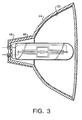
- FIG. 3 shows a schematic cross-sectional view of a preferred embodiment of a lamp assembly with an external light absorbing 48 coating on the neck 46.
- a light absorbing material such as a black topping material
- FIG. 3 shows a schematic cross-sectional view of a preferred embodiment of a lamp assembly with an external light absorbing 48 coating on the neck 46.
- the reflective coating 50 does not extend into interior the neck 46.
- the reflector is prepared, for example aluminized and then coated with absorptive material
- the reflector (20, 36, or 44) is then combined in a final lamp assembly in much the same way as a standard reflector.
- Eyelets may be located in the heel of the neck to duct the leads through the reflector which are then soldered in pace.
- a threaded brass, bayonnet, bi-pin type or similar base (not shown) may be glued or similarly attached or formed on the exterior of the reflector as is known in the art.
- Several commercial cements are available, for example Aremco, Sauereisen, etc. are well known to those skilled in the art.
- the absorptive coating is masked from those regions where the cement is needed to form a bond between the glass of the reflector and the base.
- the typical brass base can be peened in position with the indentations of the brass conforming to intentionally positioned cavities or protuberances formed on the exterior of the reflector. This process is also well known to those skilled in the art.
- the leads are electrically coupled through the reflector to the attached base for subsequent electric coupling to power the light source, also as is known in the art.
- a lens may or may not be attached to the forward edge of the reflector lip to enclose the light source in the reflector cavity.
- the lens may be melt fused, glued, or similarly coupled through an intermediary support to the reflector as known in the art.
- the reflector had a diameter of 95.25 millimeters and an axial extension of 88 millimeters.
- the neck had an opening diameter of 21 millimeters and an axial extension of 35 millimeters.
- the neck interior was coated with a silicon based blacktop material (Aremco) and cured to a hard surface.
- the black top coating had a deep gray or black color, and a diffuse surface.
- the coated reflector was then assembled as similar lamps with the insertion of a 70 watt, double ended, press sealed high intensity discharge lamp tube with a diameter of 8.6 millimeters and a length of 38 millimeters.
- the HID lamp had a sealed lamp lead that extended approximately 14 millimeters away from the enclosed volume for the discharge.
- the outer diameter of the jacket was approximately 15 millimeters; the overall length was about 65 millimeters.
- the HID lamp was installed co-axially with a reflector with one end of the sealed leads for one of the electrodes extended in the neck. The lamp was positioned in the reflector so the center of the ceramic arc tube was approximately coincident with the reflector center (focal point) of the reflector. This was approximately 32 millimeters from the base end of the lamp outer jacket. Light rays from the discharge maintained between the electrode tips can be traced to the reflective surfaces. Calculations show the light rays reflected from the neck region would normally impinge on the seal region, thereby heating the seal region. A fraction of this reflected radiation would be absorbed in the seal elevating its temperature and causing premature lamp failure.
- the light rays that propagate in the neck would be lost eventually turning into heat after multiple reflections and would not contribute usefully to the beam output.
- the lumen output with or without the blacktop was found to be approximately the same. Without the coating, normally about 3700 lumens were directed to the field for illumination. With the coating, about 3700 lumens were also directed to the field for illumination, suggesting that a large portion of the light entering the neck region is wasted being substantially turned into heat.
- the temperature of the inner lamp capsule's seal region was measured. Without the light absorbing layer, the temperature of the seal region was found to be approximately 1012 degrees Celsius, (1854 degrees Fahrenheit). With the light absorbing layer, (black topping) the temperature of the seal region was found to be about approximately 875 degrees Celsius, (1607 degrees Fahrenheit). Clearly the light absorbing layer (black topping) was substantially lowering of the temperature of the seal region. A lower seal temperature is known to extend the life of this type of lamp.
- blacktop compound normally used for halogen headlamp manufacturing, although any type of opaque absorptive paint may be used.
- blacktop compound may consist for example of an emulsion of kaolin clay, silicon powder, aluminum phosphate and water, for example, silicon blacktop from Aremco Products, Inc. Valley Cottage, NY, which cures to a durable coating upon baking.
- Other formulations may contain silicon, carbon and iron powders with butanol and glycerin as organic binders.
- An alternative black top coating may be high temperature black paint sold for repairing barbecue grills and capable of 315 degrees Celcius (600 degrees Fahrenheit) continuous operation, for example Krylon BBQ and Stove paint, Sherwin Williams, Cleveland, OH.
- the reflective coating tested was aluminum, however a multilayer dichroic coating or another high reflectivity metal such as silver, titanium or others could be used instead.
- the use of high reflective coatings for the manufacture of high quality reflectors is well known to those skilled in the art.
- the seal temperature of the 70 watt ceramic lamp in an evacuated jacket with no reflector and no lens, and burning base up in air was used as a base temperature.
- the 70 watt lamp in an evacuated jacket placed in a reflector with a lens had a seal temperature 159 degrees Celsius above the base temperature.
- the 70 watt lamp in an evacuated jacket placed in a reflector with a lens, but with no reflective coating in the neck area and a black absorptive coating on the exterior of the neck area had a seal temperature, only 23 degrees Celsius above the base temperature. The black coating reduced the seal temperature by about 136 degrees Celsius.
- a similar lamp with a 400 torr nitrogen fill in the outer jacket, not enclosed by a reflector and lens had a temperature 72 degrees Celsius below the base line.
- the nitrogen filled outer jacket lamp when enclosed in a reflector and lens as before had a seal temperature 120 degrees Celsius above the base temperature.
- the nitrogen filled outer jacket lamp when enclosed in a reflector and lens, but with the reflective material removed and black coated as before had a seal temperature 12 degrees Celsius below the base temperature.
- the results show that the ceramic lamp with the reflective coating removed and black coated in the neck area, and otherwise operated in accordance with the invention, reduced the seal area temperature by approximately 132 to 136 degrees Celsius (237 to 244 degrees Fahrenheit). This is a surprisingly high temperature difference and its reduction is expected to increase lamp life by a factor of four.
- the determination of the exact reference temperature is approximate due to uncertainties in infrared transmittances, reflectance and emittance of the surfaces between source and detector. The change in temperature as the lamp environment changed is more important as to the effectiveness of the present invention.
Landscapes
- Vessels And Coating Films For Discharge Lamps (AREA)
- Non-Portable Lighting Devices Or Systems Thereof (AREA)
- Fastening Of Light Sources Or Lamp Holders (AREA)
Abstract
Description
- FIG. 1
- shows a schematic cross-sectional view of a preferred embodiment of a lamp assembly with an internal black top coating.
- FIG. 2
- shows a schematic cross-sectional view of a preferred embodiment of a lamp assembly with a light absorbing shell material.
- FIG. 3
- shows a schematic cross-sectional view of a preferred embodiment of a lamp assembly with an external black top coating.
Claims (15)
- A PAR lamp assembly comprising:a light source having two sealed electrodes defining a lamp axis;a concave ceramic shell having an internal surface with a reflective surface formed thereon, the shell further having a neck defining a neck cavity and a reflector axis, the neck provided with an electrical connection and a mechanical support for the source,the shell surrounding the source to reflect light from the source to a field to be illuminated during lamp operation, the source and reflector being oriented with the lamp axis to be substantially co-axial with the reflector axis, and at least a portion of at least one of the electrodes extending in the neck cavity, anda substantially non-transmissive, light absorbing layer intercepting light from the source emitted in the direction of the neck.
- The lamp assembly in claim 1, wherein the light absorbing layer is coated on the interior surface of the shell in the neck.
- The lamp assembly in claim 1, wherein the shell is formed from a light transmissive material and the light absorbing layer is coated on an exterior surface of the shell adjacent the neck.
- The lamp assembly in claim 1, wherein the shell, at least in the neck, is formed from a substantially light absorbing material thereby forming the light absorbing layer, and is substantially not coated by a reflective layer in the neck interior.
- The lamp assembly in claim 1, wherein the light absorbing layer is a black top material.
- The lamp in claim 1, wherein the reflector is formed from a translucent glass.
- The lamp in claim 4, wherein the reflector is formed from an opaque glass.
- The lamp in claim 1, wherein the reflective layer is an aluminization layer.
- The lamp in claim 1, wherein the reflective layer is a dichroic coating layer.
- The lamp in claim 1, wherein the shell is a body of revolution about the reflector axis.
- The lamp in claim 1, wherein the source is further enclosed by a lamp jacket.
- The lamp in claim 1, where in the shell is closed by a lens positioned intermediate the reflective surface and the field illuminated by the lamp during lamp operation.
- The lamp in claim 1, wherein the light source is a high intensity discharge source.
- The lamp in claim 13, wherein the light source is a doubled ended source with a first axial electrode stem and a second axial electrode stem, and at least one of the electrode stems is located substantially co-axially with the reflector axis in the neck cavity.
- The lamp in claim 1, wherein the source is a ceramic metal halide high intensity discharge lamp.
Applications Claiming Priority (2)
| Application Number | Priority Date | Filing Date | Title |
|---|---|---|---|
| US120958 | 2002-04-11 | ||
| US10/120,958 US6781318B2 (en) | 2002-04-11 | 2002-04-11 | Par lamp with reduced lamp seal temperature |
Publications (2)
| Publication Number | Publication Date |
|---|---|
| EP1353358A2 true EP1353358A2 (en) | 2003-10-15 |
| EP1353358A3 EP1353358A3 (en) | 2006-06-07 |
Family
ID=28454015
Family Applications (1)
| Application Number | Title | Priority Date | Filing Date |
|---|---|---|---|
| EP03005531A Withdrawn EP1353358A3 (en) | 2002-04-11 | 2003-03-11 | Parabolic reflector lamp assembly with a light absorbing layer on the neck cavity |
Country Status (6)
| Country | Link |
|---|---|
| US (1) | US6781318B2 (en) |
| EP (1) | EP1353358A3 (en) |
| JP (1) | JP2003308709A (en) |
| KR (1) | KR100978959B1 (en) |
| CN (1) | CN100359630C (en) |
| CA (1) | CA2418181A1 (en) |
Cited By (1)
| Publication number | Priority date | Publication date | Assignee | Title |
|---|---|---|---|---|
| WO2011077331A1 (en) * | 2009-12-23 | 2011-06-30 | Koninklijke Philips Electronics N.V. | Metal halide reflector lamp |
Families Citing this family (14)
| Publication number | Priority date | Publication date | Assignee | Title |
|---|---|---|---|---|
| US7030543B2 (en) * | 2004-02-24 | 2006-04-18 | Osram Sylvania Inc. | Reflector lamp having reduced seal temperature |
| US7125149B2 (en) * | 2004-03-15 | 2006-10-24 | Osram Sylvania Inc. | Reflector lamp with reduced seal temperature |
| US7198389B1 (en) * | 2004-09-27 | 2007-04-03 | Regal King Comercial Offshore De Macau Limitada | Lamp with spot light and flood light features |
| US7563003B2 (en) * | 2004-12-13 | 2009-07-21 | Luminescent Systems, Inc. | Drop-in high intensity discharge lamp assembly and retrofit method |
| US7244047B2 (en) * | 2004-12-13 | 2007-07-17 | Luminescent Systems, Inc. | Drop-in high intensity discharge lamp assembly, and retrofit method of deploying same |
| JP2006244932A (en) * | 2005-03-04 | 2006-09-14 | Mutsuki Denki Kk | Reflector for projector light source |
| JP4547331B2 (en) * | 2005-12-28 | 2010-09-22 | パナソニック株式会社 | Lighting device and metal vapor discharge lamp |
| DE102007015483A1 (en) * | 2007-03-30 | 2008-10-02 | Osram Gesellschaft mit beschränkter Haftung | Assembly for an electric lamp with outer bulb |
| US7923908B2 (en) * | 2007-09-27 | 2011-04-12 | Osram Sylvania Inc. | Metal halide reflector lamp with beam color homogenizer |
| US20100003626A1 (en) * | 2008-07-02 | 2010-01-07 | Erich Schlosser | Ceramic Gas Collector With Electrode |
| US20120078328A1 (en) * | 2010-09-27 | 2012-03-29 | Marc Vancraeyenest | System and apparatus for treatment of biological cellular structure with electromagnetic wave energy and electromagnetic field energy sources |
| CN102563535B (en) * | 2010-12-31 | 2015-04-22 | 海洋王照明科技股份有限公司 | Reflector with radiating function and lamp provided with same |
| JP2012182014A (en) * | 2011-03-01 | 2012-09-20 | Ushio Inc | Light source device |
| DE102012219135A1 (en) * | 2012-10-19 | 2014-04-24 | Osram Gmbh | Reflector lamp i.e. retrofit lamp, has assembly clip constructed from three portions, where first portion supports light source, second portion adjusts neck and comprises pillar-like side walls, and third portion is utilized for capping |
Family Cites Families (8)
| Publication number | Priority date | Publication date | Assignee | Title |
|---|---|---|---|---|
| DE8711328U1 (en) * | 1987-08-20 | 1987-10-22 | Maurer, Ingo, 8000 München | Reflector lamp |
| US5353210A (en) * | 1989-10-10 | 1994-10-04 | General Electric Company | Reflector lamp with low UV emission |
| US5220235A (en) * | 1990-04-20 | 1993-06-15 | Koito Manufacturing Co., Ltd. | Discharge lamp device |
| KR100326687B1 (en) * | 1992-10-30 | 2002-06-20 | 요트.게.아. 롤페즈 | Electric lamp and reflector device |
| US6212004B1 (en) * | 1996-05-10 | 2001-04-03 | Applied Coatings, Inc. | Reflector with directional control of visible and infra-red radiation |
| US6163102A (en) * | 1998-05-11 | 2000-12-19 | General Electric Company | Reflector-type lamp assembly having a multi-purpose closure member |
| CA2339545A1 (en) * | 1998-06-08 | 1999-12-16 | Karlheinz Strobl | Efficient light engine systems, components and methods of manufacture |
| WO2001061730A1 (en) * | 2000-02-15 | 2001-08-23 | Koninklijke Philips Electronics N.V. | Electric lamp/reflector unit |
-
2002
- 2002-04-11 US US10/120,958 patent/US6781318B2/en not_active Expired - Lifetime
-
2003
- 2003-01-31 CA CA002418181A patent/CA2418181A1/en not_active Abandoned
- 2003-03-11 EP EP03005531A patent/EP1353358A3/en not_active Withdrawn
- 2003-04-09 KR KR1020030022246A patent/KR100978959B1/en not_active Expired - Fee Related
- 2003-04-09 JP JP2003105664A patent/JP2003308709A/en active Pending
- 2003-04-11 CN CNB031105904A patent/CN100359630C/en not_active Expired - Fee Related
Cited By (1)
| Publication number | Priority date | Publication date | Assignee | Title |
|---|---|---|---|---|
| WO2011077331A1 (en) * | 2009-12-23 | 2011-06-30 | Koninklijke Philips Electronics N.V. | Metal halide reflector lamp |
Also Published As
| Publication number | Publication date |
|---|---|
| US20030193280A1 (en) | 2003-10-16 |
| KR20030081102A (en) | 2003-10-17 |
| JP2003308709A (en) | 2003-10-31 |
| US6781318B2 (en) | 2004-08-24 |
| CN100359630C (en) | 2008-01-02 |
| EP1353358A3 (en) | 2006-06-07 |
| CA2418181A1 (en) | 2003-10-11 |
| CN1450588A (en) | 2003-10-22 |
| KR100978959B1 (en) | 2010-08-30 |
Similar Documents
| Publication | Publication Date | Title |
|---|---|---|
| US6781318B2 (en) | Par lamp with reduced lamp seal temperature | |
| EP0702396B1 (en) | High efficiency vehicle headlights and reflector lamps | |
| JP4950427B2 (en) | Reflective lamp with reduced seal temperature | |
| KR101036970B1 (en) | Metal vapor discharge lamp and lighting device | |
| US5556191A (en) | Electric reflector lamp | |
| CN1185681C (en) | Electric lamp-reflector unit | |
| EP0728366B1 (en) | Reflector lamp | |
| US5568008A (en) | Metal halide lamp with a one-part arrangement of a front cover and a reflector | |
| US7125149B2 (en) | Reflector lamp with reduced seal temperature | |
| US4174487A (en) | Mirror condenser lamp | |
| WO2011077331A1 (en) | Metal halide reflector lamp | |
| EP0160242B1 (en) | Reflector lamp and lighting systems particularly suitable for architectural lighting | |
| JPH07220685A (en) | Reflective discharge lamp and its lighting device | |
| JPS5929350A (en) | Discharge lamp device | |
| JPH06150889A (en) | Bulb | |
| JPH10334851A (en) | Shielded beam discharge lamps and outdoor shielded beam discharge lamps | |
| JP5243153B2 (en) | Luminescent container for high-intensity discharge lamp | |
| JPH01227347A (en) | Metal halide lamp for vehicle head light | |
| JPS5929344A (en) | High pressure sodium lamp | |
| JP2006048985A (en) | Metal halide lamp | |
| JPH03285251A (en) | High-pressure discharge lamp for vehicle | |
| JPH11167902A (en) | Bulbs, bulbs with reflectors and lighting fixtures | |
| JP2007323998A (en) | Fluorescent lamp | |
| JPS58192259A (en) | low pressure steam discharge lamp |
Legal Events
| Date | Code | Title | Description |
|---|---|---|---|
| PUAI | Public reference made under article 153(3) epc to a published international application that has entered the european phase |
Free format text: ORIGINAL CODE: 0009012 |
|
| AK | Designated contracting states |
Kind code of ref document: A2 Designated state(s): AT BE BG CH CY CZ DE DK EE ES FI FR GB GR HU IE IT LI LU MC NL PT RO SE SI SK TR |
|
| AX | Request for extension of the european patent |
Extension state: AL LT LV MK |
|
| PUAL | Search report despatched |
Free format text: ORIGINAL CODE: 0009013 |
|
| AK | Designated contracting states |
Kind code of ref document: A3 Designated state(s): AT BE BG CH CY CZ DE DK EE ES FI FR GB GR HU IE IT LI LU MC NL PT RO SE SI SK TR |
|
| AX | Request for extension of the european patent |
Extension state: AL LT LV MK |
|
| 17P | Request for examination filed |
Effective date: 20060710 |
|
| 17Q | First examination report despatched |
Effective date: 20060922 |
|
| AKX | Designation fees paid |
Designated state(s): DE FR GB HU NL |
|
| STAA | Information on the status of an ep patent application or granted ep patent |
Free format text: STATUS: THE APPLICATION IS DEEMED TO BE WITHDRAWN |
|
| 18D | Application deemed to be withdrawn |
Effective date: 20150429 |