EP1353211A2 - Three-dimensional transmission type microscope system, image display method and image processing apparatus - Google Patents
Three-dimensional transmission type microscope system, image display method and image processing apparatus Download PDFInfo
- Publication number
- EP1353211A2 EP1353211A2 EP03251983A EP03251983A EP1353211A2 EP 1353211 A2 EP1353211 A2 EP 1353211A2 EP 03251983 A EP03251983 A EP 03251983A EP 03251983 A EP03251983 A EP 03251983A EP 1353211 A2 EP1353211 A2 EP 1353211A2
- Authority
- EP
- European Patent Office
- Prior art keywords
- image
- signal
- transmission type
- focus degree
- signals
- Prior art date
- Legal status (The legal status is an assumption and is not a legal conclusion. Google has not performed a legal analysis and makes no representation as to the accuracy of the status listed.)
- Withdrawn
Links
Images



Classifications
-
- G—PHYSICS
- G02—OPTICS
- G02B—OPTICAL ELEMENTS, SYSTEMS OR APPARATUS
- G02B21/00—Microscopes
- G02B21/24—Base structure
- G02B21/241—Devices for focusing
- G02B21/244—Devices for focusing using image analysis techniques
-
- G—PHYSICS
- G02—OPTICS
- G02B—OPTICAL ELEMENTS, SYSTEMS OR APPARATUS
- G02B21/00—Microscopes
- G02B21/18—Arrangements with more than one light path, e.g. for comparing two specimens
- G02B21/20—Binocular arrangements
- G02B21/22—Stereoscopic arrangements
Definitions
- This invention relates to a three-dimensional transmission type microscope system and a three-dimensional image display method thereof.
- a microscope has been used for an operation such as manipulation of a gene or cell, or an assembly of a micro machine in recent years. It is necessary for the operator to bring the microscope into focus on an object in many instances since the operator looks at the object via a lens. Thus, the operator brings the microscope into focus on the object by manually changing the focal distance of the microscope in a vertical direction.
- the three-dimensional shape of the object is put in operator's mind by the operator who observes the image of each part of the object which is obtained by the focal adjustment. The operator works on the object relying on the shape of the object built in his mind.
- An all-focal microscope attracts attentions as a microscope which is in the focus in an entire view without the focusing operation by the human being's eyes.
- a microscope which focuses on an object by mechanically moving a lens is known conventionally.
- NTSC video signals from a camera is input in a PC (a computer) successively by an ADC and the image data is stored in a memory provided in the PC, even if it uses video signals of an interlace, it is impossible to take in data at more than 30 frame/sec frame rate.
- a vision chip has been developed in order to accelerate an image input and processing in recent years. Specifically, development of the C-MOS vision chip which can read an arbitrary area on an image device is performed briskly.
- the structure of the vision system is based on a PC, and has a problem that a sufficient band for data transmission cannot be secured.
- the vision chips (2) and (3) have high data transmission band and high processing ability since image information can be taken in the system in parallel.
- the vision chip (3) Since especially the vision chip (3) has the super parallel processing ability, data is transmitted and processed at a high-speed, but since the vision chip (3) has not crossed the stage of a trial production yet, it is difficult to secure sufficient image resolution.
- a cell positioning method comprises a step of, by a television camera, observing a light image reflected from and transmitted to cells which emit fluorescence by giving fluorescein, and cells which do not emit fluorescence by giving fluorescein, observing these objects by using fluorescence microscope, scanning the object by a TV camera, distinguishing the cells which emit fluorescence, from the cells which do not emit fluorescence by binary processing of light image reflected from the scanned cells and storing the binary fluorescence image of the cells which emit fluorescence in a frame memory, storing the binary data of the cells that emit fluorescence in a frame memory and overlaying the fluorescence image and transmission light image on a monitor or displaying these images side by side on the monitor.
- an IQM image (signal) indicating in-focus degree in each pixel position at each focal distance is used to obtain an all-focal image (or images) and a depth image (or images). (That is, 4 channels of RGB+IQM are used to obtain the all-focal image.)
- Partial space frequency analysis of a picture is performed in the position in a certain picture, moving optical distance (the picture distance x, the object distance X, or a focal length f).
- the peak of the frequency obtained by the local space frequency analysis about an image within a certain area while the focal distance is changed indicates that the image is in focus.
- the peak frequency By analyzing the peak frequency, the image in focus at each focal distance is identified and synthesized.
- the depth image can be obtained from an object distance X in the place where each portion is in focus.
- an all-focal image is generated by gathering up only in-focus portions from two or more images obtained while changing the optical distance, and the depth image generated from the object distance X at which the good portions are captured at that time.
- the technology which displays the inside of an object by four channels of RGBP (the transparency P of the object is added to the RGB 3 channels of each slice image of the object) is used as volume rendering technology which displays three-dimensional Computer Graphic.
- a P value of glass is high, an opaque object is set as a low P value, and frosted glass in the middle.
- in-focus degree IQM By relating, in the look-up table (a memory means, or memory storage) , in-focus degree IQM and the transparency P used for the volume rendering technology, it is possible to display a volume rendering image based on a series of images obtained while the focal distance is changed. Thereby, it is possible to observe the inside of the object like an MRI image. Furthermore, it is possible to display slice images in an arbitrary direction such as a vertical or horizontal direction but not limited to these directions).
- a three-dimensional transmission type microscope system has a transmission type micro scope, and an image processing apparatus which processes a pixel signal obtained as RGB signals and an in-focus degree signal from the transmission type micro scope, the image processing apparatus having a memory and a processing unit, wherein the in-focus degree signal and a transparent signal are related to each other and stored in the memory, the in-focus degree signal is converted into the transparent signal, and image pixel signal is generated for displaying an image on a screen by the processing unit.
- a three-dimensional transmission type microscope system including a transmission type micro scope and an image-processing apparatus which processes RGB signals and an in-focus degree signal obtained from the transmission type micro scope, the three-dimensional transmission type microscope system, wherein the in-focus degree signal is converted into a transparent signal, and an image signal for display is generated based on the RGB signals and the transparent signal.
- a three-dimensional transmission type microscope system including a transmission type fluorescence micro scope and an image-processing apparatus which processes RGB signals and an in-focus degree signal obtained from the transmission type fluorescence micro scope, the three-dimensional transmission type microscope system, wherein the RGB signals and the in-focus degree signal are stored, the stored in-focus degree signal is converted into a transparent signal, and an image signal for display is generated based on the RGB signals and the transparent signal.
- volume rendering image may be displayed off line.
- a transmission type fluorescence microscope system in which excitation light is emitted on a sample, fluorescent light excited from the sample by the excitation light is observed
- the transmission type fluorescence microscope system includes a fluorescence microscope, a processing unit, wherein while focal distance is changed, RGB signals and an in-focus degree signal are obtained, and a plurality of depth images comprising all-focal images are generated from the RGB signals and the in-focus degree signal obtained by fluorescence excited by excitation light which transmits inside the sample
- the image processing unit converts the in-focus degree signal into a transparency signal
- an image signal is generated by the RGB signals and the transparency signal
- a depth image comprising all-focal image is generated to display the inside of the sample.
- an image display method for displaying an image by processing RGB signals and an in-focus degree signal obtained from the 3-dimensiional transmission type microscope, the image display method comprising, steps of storing, with respect to fluorescence image, the RGB signals and the in-focus degree signal from, converting the in-focus degree signal to a transparency signal, and forming an image signal for display, by the transparency signal and the RGB channel signals.
- an image display method for displaying an image by processing RGB signals and an in-focus degree signal obtained from the 3-dimensiional transmission type fluorescence microscope comprising, steps of storing, the RGB signals and the in-focus degree signal fluorescence image obtained from the fluorescence transmission type microscope, converting the in-focus degree signal to a transparency signal, and forming an image for display, by the transparency degree signal and the RGB channel signals.
- the image for display may be refreshed 3 to 4 times for neuron reaction time of human's brain.
- an image display method for displaying an image of protein by processing RGB signals and an in-focus degree signal obtained from a transmission type fluorescence microscope, the image display method comprising, steps of changing a focal distance of the transmission type fluorescence microscope to the protein, generating a plurality of transmission images comprising a series of images from the RGB 3 signals and the in focus degree signal, a transparency signal obtained from fluorescence excited by excitation light which transmits an inside of cells of the protein, converting the in-focus degree signal into transparency signal, forming an image to be display by the RGB 3 signals and the transparency signal, displaying an image of the inside of the protein cells.
- an image processing apparatus includes a memory for storing an image signal, means for obtaining an in-focus degree signal from the image signal, means for generating a transparent signal based on the in-focus degree signal; and means for generating display image signals for a three-dimensional image based on the image signals and the transparent signal.
- Fig. 1 is a schematic block diagram of a three-dimensional transmission type microscope system according to the present invention.
- the transmission type microscope 2 has an optical system 11 that receives reflected light from an object OB, and a high-speed scanning camera 12 (that comprises the camera head of the transmission type microscope 2)d as a high-speed scanning device to which the optical system 11 is attached.
- a high-speed scanning camera 12 that comprises the camera head of the transmission type microscope 2d as a high-speed scanning device to which the optical system 11 is attached.
- An image processing apparatus 13 connected to the three-dimensional transmission type microscope 2, takes in data scanned by the high-speed scanning camera 12, processes at high speed, and generates all-focal images.
- the image processing apparatus 13 connected to an image display device 15 has a CPU as a processing equipment 16 and an image memory 17.
- a display device of the processing apparatus 16 may be used as the image display device 15. In this embodiment, both image display device 15 and processing apparatus 16 are shown in the Fig. 1 for convenience.
- the image processing apparatus 13 has a RGB output board 14 which performs color processing to the all-focal images that the image processing apparatus 13 has generated, and an in-focus degree output board 18 that is used with the RGB output board 14.
- the microscope is equipped with a focal distance changing device 26.
- the optical system 11 has a variable focal mechanism 11A and micro zoom lens(es) 11C and a lighting system 11B.
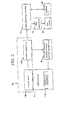
- Fig. 2 a functional block diagram mainly showing function of the three-dimensional transmission type microscope system 1 is shown.
- the high-speed scanning camera 12 is equipped with a camera sensor 12A and a camera output circuit 12B that processes an output signal of the camera sensor 12.
- the optical system 11 is equipped with the variable focal mechanism 11A positioning the optical system 11 in order from the side near the object OB, the lighting system 11B, and the zoom lens 11C.
- variable focal mechanism 11A is provided on the lighting system 11B which is provided on the macro zoom lens 11C. Thereby, the variable focal mechanism system which changes the original optical characteristic (focal distance) of a macro zoom lens at a high speed is acquired.
- Fig. 3 is a timing chart showing driving timings at which the focal distance changing device 16 drives the variable focal mechanism 11A. It is controlled to photo (scan) the object OB eight (8) times for every focal distance synchronizing with a 30Hz sawtooth waveform, as shown in Fig. 3.
- the sawtooth wave is generated by the focal distance changing device 26 using the synchronized signal sent from the camera output circuit 12B of the high-speed scanning camera 12.
- the hysteresis is surely reset for every waveform (every scanning).
- the frame rate of the high-speed scanning camera is usually increased by one of the following methods or the combination thereof:
- the technique of reducing the number of reading pixels is accomplished by, for example, reading by only 250 x 250 pixels by a sensor which can read 500 x 500 pixels by 30 frames and progressing to the next frame.
- the Parallelization of the reading pixel is performed in various modes.
- the high-speed camera (“ULTIMA” Series manufactured by Photron Ltd.) has an array of 16 independent high-speed sensors (each of which has 16 x 256 pixels) that are in parallel arranged, and these sensors forms a scanning area of 256 x 256 pixels as a whole. Each high-speed sensor is read at 25 MHz.
- the third technique of parallelization mentioned above is used for the camera sensor 12A of the high-speed scanning camera 12.
- the high-speed image sensors for scanning are provided in an arrangement of array.
- this high-speed scanning camera 12 may consist of the 2nd technique mentioned above or the combination of the 2nd and the 3rd techniques.
- a pixel area (for example, 256 x 256 pixels) of one sheet forming a scanning area can be divided vertically and horizontally into two or more areas(for example, four areas), and pixel data can be simultaneously read in parallel from each divided area, thereby the system can accelerate reading speed.
- the pixel data for two or more lines (for example, two lines: each line, for example, comprises 256 pixels) from the pixel area of one sheet is simultaneously read in parallel, and this operation is performed one by one about all lines, thereby the system can accelerate reading speed.
- pixel data can be simultaneously and in parallel read from two or more pixels (for example, 10 pixels) from a line (for example, 256 pixels) which constitutes the pixel area of one sheet, thereby the system can accelerate reading speed by repeating this operation successively about the line and remaining lines.
- the camera output circuit 12B is equipped with the processing circuit section equipped with circuits, such as an amplifier, a CDS (Correlated Double Sampling) circuit, and an A/D converter, corresponding to each sensor in addition to a clock generator.
- circuits such as an amplifier, a CDS (Correlated Double Sampling) circuit, and an A/D converter, corresponding to each sensor in addition to a clock generator.
- image data from the camera sensor 12A is amplified, CDS-processed, and digitized for every processing circuit section.
- Data outputted from this camera output circuit 12B is transmitted to the image processing apparatus 13 by the LVDS (Low Voltage Differential Signaling) method.
- LVDS Low Voltage Differential Signaling
- the image processing apparatus 13 comprises of hardware logic based on a high-speed mass FPGA (Field Programmable Gate Array).
- This image processing apparatus 13 includes an FPGA, mass SDRAM, and an LVDS interface on its board, and can interface with external apparatuses.
- in-focus degree IQM Image Quality Measure
- the IQM is explained below.
- the IQM is based on the optical theory called “Depth from Focus” theory.
- “Depth from Focus” theory Refer to, for example, Masahiro Watanabe and Shree K. Nayer, " Minimal Operator Set for Passive Depth from Defocus ,” CVPR '96, pp.431-438 (1996), Shree K.Nayer, Masahiro Watanabe, and Minoryu Noguchi, " Real-Time Focus Range Sensor ,” ICCV '95, pp.995-1001, (1995), Shree K.Nayer, and Yasuo Nakagawa, " Shape from Focus ,” IEEE Trans. on PAMI, Vol.16, No.8, pp.824-831 (1994), A.P.
- Pentland " A New Sense for Depth of Field ", IEEE Trans. On Pattern Analysis and Machine Intelligence, Vol. PAMI-9, No.4, pp.523-531, (1987), Michio Miwa, Tomoyuki Oohara, Masahiko Ishii, Yasuharu Koike, and Makoto Sato, "A Method of Far Object Recognition using Depth from Focus," Proc. 3D Image Conference '99, pp.305-307 (1999), and etc.)
- portions which are out of focus have low frequency and portions which are in focus have high frequency.
- Images are captured one by one as focal distance of the lens is changed by the variable focal mechanism 11A.
- the local space frequency analysis of each picture is performed about the image, and the image portion having the peak of frequency, i.e., the in-focus portion (or portions) is taken up from each image in a pixel unite, and these image portions extracted are synthesized as a sheet of an image, thereby, an all-focal image is obtained.
- the three-dimensional data of the object OB which is reflected in the all-focal picture is also obtained at those focal distances.
- IQM Image Quality Measure
- (-Lc, -Lr) - (Lc, Lr) and (x i , y i ) - (x f , y f ) represent the small areas for performing distribution evaluation and smoothing, respectively.
- D represents the number of all the pixels which is evaluated for normalizating them per pixel.
- the focal distance is changed by the variable focal mechanism 11A, the value of IQM is evaluated for each pixel or each area, the peak of an IQM value is detected, and the object distance X then computed from the pixel shade value f and the image distance x is substituted for the matrix element to each pixel position, respectively.
- each matrix becomes an all-focal image and a depth picture.
- the output of the Laplacian circuit is compared with a reference value or peak value stored in the peak memory, and if it is the peak value, i.e., the image is in focus, it is recorded in the frame memory in SDRAM. The other outputs data is deleted.
- the processed image data stored in the SDRAM is sent in the form of standard NTSC signals at frame rate 30Hz, to the monitor (image display device) 15 through the RGB output board 14, and is displayed as a real time all-focal image.
- the three-dimensional data which consists of a focal distance is converted to LVDS, and is transmitted to the processing equipment 16.
- a camera image can be obtained by the three-dimensional transmission type microscope which is a real time all-focal type, and an operator does not need to imagine the three-dimensional shape of an object in mind.
- the frame frequency of a motion picture which a person can regard as one without breaks is 30 or more frames per second.
- the technology which displays the inside of an object by four channels of RGBP which added transparency P of the object to 3 RGB channels of each slice image is used as volume rendering technology which displays three-dimensional CG.
- a P value of glass is high, an opaque object is set as a low P value, and frosted glass has a middle value.
- in-up table 21 a memory means, or memory storage
- in-focus degree IQM 22 and the transparency P 23 used for volume rendering technology it is possible to display volume rendering images, based on a series of images obtained while the focal distance is changed. Thereby, it is possible to observe the inside of the object like an MRI image. Furthermore, it is possible to display the slice image in the arbitrary direction (such as a vertical direction or horizontal direction but not limited to these directions).
- neuron reaction time 3 to 4 milliseconds
- FIG. 7 A flow chart is shown in Fig. 7.
- Focal distance FV 0
- S3 an original image ORG of the RGB 3 channel (FV, x, y)
- IQM (FV, x, y) and Transparency P (FV, x, y) are related to each other in look-up table 21 LUT (S5). It is determined if FV ⁇ FVmax (S6). If FV is less than FVmax, a focal distance is changed and the above-mentioned step is repeated. If FV is more than FVmax, a volume rendering is performed about ORG(FV, x, y) + P(FV, x, y) data (S7), and an image is displayed on the screen display.
- Fig. 8 shows sliced images obtained while the focal distance was changed.
- Fig. 9 like an MRI image, the entire view 41 of a three-dimensional microscope image to which volume rendering is performed, is shown on the display screen 40.
- horizontal slice image 42 and vertical slice image 43 are shown on the display screen 40.
- the three-dimensional transmission type microscope system comprises the transmission type microscope and an image processing apparatus which carries out image processing of a pixel signal of the image obtained by the transmission type microscope.
- the above-mentioned pixel signal outputted as RGB channel signals and a channel signal of in-focus degree from the transmission type microscope are stored in the memory or memories.
- a transparent channel signal is generated based on the stored channel signal of in-focus degree, and forms a pixel signal together with the RGB channel signals to display an image on the display screen.
- a three-dimensional transmission type microscope system comprises a transmission type fluorescence microscope and an image-processing apparatus which carries out image processing of the pixel signal of the image obtained by the transmission type fluorescence microscope.
- the pixel signal outputted as RGB channel signals and a channel signal of in-focus degree from the transmission type microscope are stored in a memory or memories.
- a transparent signal is generated based on the stored channel signal of in-focus degree, and forms a pixel signal together with the RGB channel signals to display an image on a display screen.
- a transmission type fluorescence microscope system used for observation of fluorescence excited from an object by excitation light comprises a transmission type fluorescence microscope and image processing apparatus wherein focal distance to the object is controlled, and a depth image consist of an all-focal image of fluorescence excited by excitation light which transmits inside the object are formed by a pixel signal comprising RGB 3 channel signals and a channel signal of in-focus degree.
- the image processing apparatus converts the in-focus degree channel signal into transparent channel signal by using the generated the pixel signal thereby the pixel signal for the screen display is formed by the RGB 3 channel signals and the transparent signal and further, a depth image consisting of all-focal image is generated to display the inside of the object by the pixel signal on the screen display.
- an image display method of a three-dimensional transmission type microscope comprises steps of storing, with respect to fluorescence image, the pixel signal outputted as RGB channel signals and a channel signal of in-focus degree from the transmission type microscope; generating transparent signal based on the stored channel signal of in-focus degree; and forming a pixel signal by the channel signal of in-focus degree and the RGB channel signals to display an image on a display screen.
- volume rendering image may be displayed off line.
- an image display method for displaying an image of the protein (crystal) by processing a pixel signal of the image obtained from a transmission type fluorescence microscope comprises steps of controlling and changing focal distance to the protein, forming a plurality of transmission images consisting of a series of images from pixels consisting of RGB 3 channel signals and a transparent channel signal by the fluorescence excited by the excitation light which transmits the inside of cells of the protein, converting a channel signal of in-focus degree into a transparent channel signal, generating a pixel signal for display screen by the RGB 3 channel signals and the transparent channel signal, generating and displaying an image of the inside of the protein cells by the pixel signal.
- the image display method of a three-dimensional transmission type microscope three to four images are refreshed for neutron reaction time (3 to 4 msec) of human brain on the display screens
- the inside of an object can be clearly displayed by using four channels consisting of RGB channels and P transparency channel based on an image obtained in form of RGB 3 channels and an IQM channel from an object (sample), and the entire view inside an object can be further displayed three-dimensionally like an MRI picture.
- fluorescence of an object according to in-focus degree can be related to transparency, and observation of the three-dimensional structure of a fluorescent substance is attained.
Landscapes
- Physics & Mathematics (AREA)
- Chemical & Material Sciences (AREA)
- Analytical Chemistry (AREA)
- General Physics & Mathematics (AREA)
- Optics & Photonics (AREA)
- Engineering & Computer Science (AREA)
- Computer Vision & Pattern Recognition (AREA)
- Microscoopes, Condenser (AREA)
- Closed-Circuit Television Systems (AREA)
- Color Television Image Signal Generators (AREA)
Abstract
Description
It is controlled to photo (scan) the object OB eight (8) times for every focal distance synchronizing with a 30Hz sawtooth waveform, as shown in Fig. 3.

If FV is more than FVmax, a volume rendering is performed about ORG(FV, x, y) + P(FV, x, y) data (S7), and an image is displayed on the screen display.
Claims (9)
- A three-dimensional transmission type microscope system comprising:a transmission type micro scope; andan image processing apparatus which processes a pixel signal obtained as RGB signals and an in-focus degree signal from the transmission type micro scope, the image processing apparatus having a memory and a processing unit,
wherein the in-focus degree signal and transparent signal are related to each other and stored in the memory,the in-focus degree signal is converted into the transparent signal, andimage pixel signal is generated for displaying an image on a screen by the processing unit. - A three-dimensional transmission type microscope system including a transmission type micro scope and an image-processing apparatus which processes RGB signals and an in-focus degree signal obtained from the transmission type micro scope, the three-dimensional transmission type microscope system,
wherein the in-focus degree signal is converted into transparent signal, and
an image signal for display are generated based on the RGB signals and the transparent signal. - A three-dimensional transmission type microscope system including a transmission type fluorescence micro scope and an image-processing apparatus which processes RGB signals and an in-focus degree signal obtained from the transmission type fluorescence micro scope, the three-dimensional transmission type microscope system,
wherein the RGB signals and the in-focus degree signal are stored,
the stored in-focus degree signal is converted into a transparent signal, and
an image signal for display is generated based on the RGB s and the transparent signal. - A transmission type fluorescence microscope system in which excitation light is emitted on a sample, fluorescent light excited from the sample by the excitation light is observed, the transmission type fluorescence microscope system comprising:a fluorescence microscope;a processing unit;
wherein while focal distance is changed, RGB signals and an in-focus degree signal are obtained, and a plurality of depth images comprising all-focal images are generated from the RGB signals and the in-focus degree signal obtained by fluorescence excited by excitation light which transmits inside the sample;the image processing unit converts the in-focus degree signal into a transparency signal,an image signal is generated by the RGB signals and the transparency signal, anda depth image comprising all-focal image is generated to display the inside of the sample. - An image display method for displaying an image by processing RGB signals and an in-focus degree signal obtained from the 3-dimensiional transmission type microscope, the image display method comprising, steps of:storing, with respect to fluorescence image, the RGB signals and the in-focus degree signal from;converting the in-focus degree signal to a transparency signal; andforming an image signal for display, by the transparency signal and the RGB channel signals.
- An image display method for displaying an image by processing RGB signals and an in-focus degree signal obtained from the 3-dimensiional transmission type fluorescence microscope, the image display method comprising, steps of:storing, the RGB signals and the in-focus degree signal fluorescence image obtained from the fluorescence transmission type microscope;converting the in-focus degree signal to a transparency signal; andforming an image for display, by the transparency degree signal and the RGB channel signals.
- The image display method according to claim 6, wherein the image for display is refreshed 3 to 4 times for neuron reaction time of human's brain
- an image display method for displaying an image of protein by processing RGB signals and an in-focus degree signal obtained from a transmission type fluorescence microscope, the image display method comprising, steps of:changing a focal distance of the transmission type fluorescence microscope to the protein,generating a plurality of transmission images comprising a series of images from the RGB 3 signals and the in focus degree signala transparency signal obtained from fluorescence excited by excitation light which transmits an inside of cells of the protein,converting the in-focus degree signal into a transparency signal,forming an image to be display by the RGB 3 signals and the transparency signal,displaying an image of the inside of the protein cells.
- An image processing apparatus comprising:means for obtaining image signals at plural focal points;at least one memory for storing the image signals;means for obtaining in-focus degree signals from the image signals;means for relating at least one transparent signal to the in-focus signals; andmeans for generating at least one display image signal for a three-dimensional image based on the image signals, the at least one in-focus degree signal and the at least one transparent signal.
Applications Claiming Priority (2)
| Application Number | Priority Date | Filing Date | Title |
|---|---|---|---|
| JP2002092349A JP3627020B2 (en) | 2002-03-28 | 2002-03-28 | Three-dimensional transmission microscope system and image display method |
| JP2002092349 | 2002-03-28 |
Publications (2)
| Publication Number | Publication Date |
|---|---|
| EP1353211A2 true EP1353211A2 (en) | 2003-10-15 |
| EP1353211A3 EP1353211A3 (en) | 2004-01-21 |
Family
ID=28449625
Family Applications (1)
| Application Number | Title | Priority Date | Filing Date |
|---|---|---|---|
| EP03251983A Withdrawn EP1353211A3 (en) | 2002-03-28 | 2003-03-28 | Three-dimensional transmission type microscope system, image display method and image processing apparatus |
Country Status (3)
| Country | Link |
|---|---|
| US (1) | US20030184558A1 (en) |
| EP (1) | EP1353211A3 (en) |
| JP (1) | JP3627020B2 (en) |
Families Citing this family (13)
| Publication number | Priority date | Publication date | Assignee | Title |
|---|---|---|---|---|
| US7526118B2 (en) * | 2003-08-06 | 2009-04-28 | Quality Vision International, Inc | Digital video optical inspection apparatus and method for vertically sectioning an object's surface |
| DE102004034954A1 (en) * | 2004-07-16 | 2006-02-02 | Carl Zeiss Jena Gmbh | Method for detecting at least one sample area with a light scanning microscope |
| JP2006113462A (en) * | 2004-10-18 | 2006-04-27 | Tohoku Univ | Single particle 3D position tracking method |
| DE102006030530A1 (en) * | 2006-07-01 | 2008-01-03 | Carl Zeiss Microimaging Gmbh | Method and device for detecting light signals |
| US9041791B2 (en) * | 2011-02-01 | 2015-05-26 | Roche Diagnostics Hematology, Inc. | Fast auto-focus in imaging |
| JP5747690B2 (en) * | 2011-07-04 | 2015-07-15 | 株式会社ニコン | Microscope device and image forming method |
| JP5928308B2 (en) * | 2012-11-13 | 2016-06-01 | ソニー株式会社 | Image acquisition apparatus and image acquisition method |
| CN111978921A (en) | 2013-09-30 | 2020-11-24 | 圣戈本陶瓷及塑料股份有限公司 | Shaped abrasive particles and methods of forming the same |
| KR102081045B1 (en) | 2013-12-31 | 2020-02-26 | 생-고뱅 어브레이시브즈, 인코포레이티드 | Abrasive article including shaped abrasive particles |
| US9914864B2 (en) | 2014-12-23 | 2018-03-13 | Saint-Gobain Ceramics & Plastics, Inc. | Shaped abrasive particles and method of forming same |
| EP4081370A4 (en) | 2019-12-27 | 2024-04-24 | Saint-Gobain Ceramics & Plastics Inc. | Abrasive articles and methods of forming same |
| MX2024007593A (en) | 2021-12-30 | 2024-08-20 | Saint Gobain Abrasives Inc | Abrasive articles and methods of forming same. |
| CN115299872A (en) * | 2022-08-08 | 2022-11-08 | 中山大学中山眼科中心 | Fluorescence imaging device for conjunctival goblet cells |
Family Cites Families (9)
| Publication number | Priority date | Publication date | Assignee | Title |
|---|---|---|---|---|
| US5932872A (en) * | 1994-07-01 | 1999-08-03 | Jeffrey H. Price | Autofocus system for scanning microscopy having a volume image formation |
| WO1996012981A1 (en) * | 1994-10-21 | 1996-05-02 | Kla Instruments Corporation | Autofocusing apparatus and method for high resolution microscope system |
| US5671085A (en) * | 1995-02-03 | 1997-09-23 | The Regents Of The University Of California | Method and apparatus for three-dimensional microscopy with enhanced depth resolution |
| JP3961729B2 (en) * | 1999-03-03 | 2007-08-22 | 株式会社デンソー | All-focus imaging device |
| JP2001100594A (en) * | 1999-09-28 | 2001-04-13 | Stanley Electric Co Ltd | Manufacturing method of electrophotographic photoreceptor |
| US6555802B2 (en) * | 2000-01-07 | 2003-04-29 | Axon Instruments, Inc. | Scanning microscope |
| US20010033287A1 (en) * | 2000-01-11 | 2001-10-25 | Sun Microsystems, Inc. | Graphics system having a super-sampled sample buffer which utilizes a window ID to specify pixel characteristics |
| DE10145056A1 (en) * | 2001-09-13 | 2003-04-03 | Zeiss Carl Jena Gmbh | Device and method for focus control in a microscope with digital imaging, preferably a confocal microscope |
| US7084910B2 (en) * | 2002-02-08 | 2006-08-01 | Hewlett-Packard Development Company, L.P. | System and method for using multiple images in a digital image capture device |
-
2002
- 2002-03-28 JP JP2002092349A patent/JP3627020B2/en not_active Expired - Lifetime
-
2003
- 2003-03-28 EP EP03251983A patent/EP1353211A3/en not_active Withdrawn
- 2003-03-28 US US10/400,485 patent/US20030184558A1/en not_active Abandoned
Also Published As
| Publication number | Publication date |
|---|---|
| JP3627020B2 (en) | 2005-03-09 |
| US20030184558A1 (en) | 2003-10-02 |
| EP1353211A3 (en) | 2004-01-21 |
| JP2003287687A (en) | 2003-10-10 |
Similar Documents
| Publication | Publication Date | Title |
|---|---|---|
| EP1515174A2 (en) | Three dimensional microscope system and image display method thereof | |
| EP1381229B1 (en) | Real-time omnifocus microscope camera | |
| US20030184558A1 (en) | Three-dimensional transmission type microscope system, image display method and image processing apparatus | |
| US6133945A (en) | Method and device for showing stereoscopic video images on a display | |
| US10142566B2 (en) | Rolling readout type camera and imaging method for using the same | |
| US20140015933A1 (en) | Image processing apparatus, imaging system, and image processing system | |
| US20150153559A1 (en) | Image processing apparatus, imaging system, and image processing system | |
| US20210295502A1 (en) | Medical image processing device and medical observation system | |
| CN109031642B (en) | Universal stereoscopic microscopic naked eye visualization display method and system device | |
| CN112274105A (en) | Operating microscope, image processing device and image processing method | |
| JP6296365B2 (en) | Surgical endoscope camera control unit | |
| JP2010283724A (en) | Imaging apparatus and microscope system | |
| JPH11352613A (en) | Image recorder and image reproducing device | |
| JP3501359B2 (en) | All-focus imaging method and stereoscopic display method | |
| JP2007295326A (en) | Multifocal imaging device | |
| JP2861634B2 (en) | Method and apparatus for recognizing three-dimensional object | |
| US6229928B1 (en) | Image processing system for removing blur using a spatial filter which performs a convolution of image data with a matrix of no-neighbor algorithm based coefficients | |
| JP2010170025A (en) | Image output system, image output method, and image output program | |
| TWI714378B (en) | A large-angle optical raster scanning system for high speed deep tissue imaging | |
| CN101785655B (en) | Image collection device in organisms | |
| JP7030986B2 (en) | Image generator, image generator and image generator | |
| JP2004029537A (en) | Microscope, three-dimensional image generating method, program for making computer perform control of generating three-dimensional image and recording medium having the program recorded thereon | |
| JP2001218116A (en) | Imaging equipment | |
| US20260011077A1 (en) | Image processing apparatus, image processing method, and storage medium | |
| JP3317443B2 (en) | Sample observation device |
Legal Events
| Date | Code | Title | Description |
|---|---|---|---|
| PUAI | Public reference made under article 153(3) epc to a published international application that has entered the european phase |
Free format text: ORIGINAL CODE: 0009012 |
|
| AK | Designated contracting states |
Kind code of ref document: A2 Designated state(s): AT BE BG CH CY CZ DE DK EE ES FI FR GB GR HU IE IT LI LU MC NL PT RO SE SI SK TR |
|
| AX | Request for extension of the european patent |
Extension state: AL LT LV MK |
|
| PUAL | Search report despatched |
Free format text: ORIGINAL CODE: 0009013 |
|
| AK | Designated contracting states |
Kind code of ref document: A3 Designated state(s): AT BE BG CH CY CZ DE DK EE ES FI FR GB GR HU IE IT LI LU MC NL PT RO SE SI SK TR |
|
| AX | Request for extension of the european patent |
Extension state: AL LT LV MK |
|
| RIC1 | Information provided on ipc code assigned before grant |
Ipc: 7G 02B 21/22 B Ipc: 7G 02B 21/24 A |
|
| AKX | Designation fees paid | ||
| REG | Reference to a national code |
Ref country code: DE Ref legal event code: 8566 |
|
| STAA | Information on the status of an ep patent application or granted ep patent |
Free format text: STATUS: THE APPLICATION IS DEEMED TO BE WITHDRAWN |
|
| 18D | Application deemed to be withdrawn |
Effective date: 20040722 |