EP1353177A2 - A method to calculate fuel DI number from a measured curve - Google Patents
A method to calculate fuel DI number from a measured curve Download PDFInfo
- Publication number
- EP1353177A2 EP1353177A2 EP03075858A EP03075858A EP1353177A2 EP 1353177 A2 EP1353177 A2 EP 1353177A2 EP 03075858 A EP03075858 A EP 03075858A EP 03075858 A EP03075858 A EP 03075858A EP 1353177 A2 EP1353177 A2 EP 1353177A2
- Authority
- EP
- European Patent Office
- Prior art keywords
- fuel
- sensor
- volume
- temperatures
- value
- Prior art date
- Legal status (The legal status is an assumption and is not a legal conclusion. Google has not performed a legal analysis and makes no representation as to the accuracy of the status listed.)
- Granted
Links
Images


Classifications
-
- G—PHYSICS
- G01—MEASURING; TESTING
- G01N—INVESTIGATING OR ANALYSING MATERIALS BY DETERMINING THEIR CHEMICAL OR PHYSICAL PROPERTIES
- G01N33/00—Investigating or analysing materials by specific methods not covered by groups G01N1/00 - G01N31/00
- G01N33/26—Oils; Viscous liquids; Paints; Inks
- G01N33/28—Oils, i.e. hydrocarbon liquids
- G01N33/2829—Mixtures of fuels
-
- F—MECHANICAL ENGINEERING; LIGHTING; HEATING; WEAPONS; BLASTING
- F02—COMBUSTION ENGINES; HOT-GAS OR COMBUSTION-PRODUCT ENGINE PLANTS
- F02D—CONTROLLING COMBUSTION ENGINES
- F02D19/00—Controlling engines characterised by their use of non-liquid fuels, pluralities of fuels, or non-fuel substances added to the combustible mixtures
- F02D19/06—Controlling engines characterised by their use of non-liquid fuels, pluralities of fuels, or non-fuel substances added to the combustible mixtures peculiar to engines working with pluralities of fuels, e.g. alternatively with light and heavy fuel oil, other than engines indifferent to the fuel consumed
- F02D19/0626—Measuring or estimating parameters related to the fuel supply system
- F02D19/0628—Determining the fuel pressure, temperature or flow, the fuel tank fill level or a valve position
-
- F—MECHANICAL ENGINEERING; LIGHTING; HEATING; WEAPONS; BLASTING
- F02—COMBUSTION ENGINES; HOT-GAS OR COMBUSTION-PRODUCT ENGINE PLANTS
- F02D—CONTROLLING COMBUSTION ENGINES
- F02D19/00—Controlling engines characterised by their use of non-liquid fuels, pluralities of fuels, or non-fuel substances added to the combustible mixtures
- F02D19/06—Controlling engines characterised by their use of non-liquid fuels, pluralities of fuels, or non-fuel substances added to the combustible mixtures peculiar to engines working with pluralities of fuels, e.g. alternatively with light and heavy fuel oil, other than engines indifferent to the fuel consumed
- F02D19/0626—Measuring or estimating parameters related to the fuel supply system
- F02D19/0634—Determining a density, viscosity, composition or concentration
-
- F—MECHANICAL ENGINEERING; LIGHTING; HEATING; WEAPONS; BLASTING
- F02—COMBUSTION ENGINES; HOT-GAS OR COMBUSTION-PRODUCT ENGINE PLANTS
- F02D—CONTROLLING COMBUSTION ENGINES
- F02D19/00—Controlling engines characterised by their use of non-liquid fuels, pluralities of fuels, or non-fuel substances added to the combustible mixtures
- F02D19/06—Controlling engines characterised by their use of non-liquid fuels, pluralities of fuels, or non-fuel substances added to the combustible mixtures peculiar to engines working with pluralities of fuels, e.g. alternatively with light and heavy fuel oil, other than engines indifferent to the fuel consumed
- F02D19/0639—Controlling engines characterised by their use of non-liquid fuels, pluralities of fuels, or non-fuel substances added to the combustible mixtures peculiar to engines working with pluralities of fuels, e.g. alternatively with light and heavy fuel oil, other than engines indifferent to the fuel consumed characterised by the type of fuels
- F02D19/0649—Liquid fuels having different boiling temperatures, volatilities, densities, viscosities, cetane or octane numbers
-
- F—MECHANICAL ENGINEERING; LIGHTING; HEATING; WEAPONS; BLASTING
- F02—COMBUSTION ENGINES; HOT-GAS OR COMBUSTION-PRODUCT ENGINE PLANTS
- F02D—CONTROLLING COMBUSTION ENGINES
- F02D19/00—Controlling engines characterised by their use of non-liquid fuels, pluralities of fuels, or non-fuel substances added to the combustible mixtures
- F02D19/06—Controlling engines characterised by their use of non-liquid fuels, pluralities of fuels, or non-fuel substances added to the combustible mixtures peculiar to engines working with pluralities of fuels, e.g. alternatively with light and heavy fuel oil, other than engines indifferent to the fuel consumed
- F02D19/0663—Details on the fuel supply system, e.g. tanks, valves, pipes, pumps, rails, injectors or mixers
- F02D19/0665—Tanks, e.g. multiple tanks
-
- F—MECHANICAL ENGINEERING; LIGHTING; HEATING; WEAPONS; BLASTING
- F02—COMBUSTION ENGINES; HOT-GAS OR COMBUSTION-PRODUCT ENGINE PLANTS
- F02D—CONTROLLING COMBUSTION ENGINES
- F02D2200/00—Input parameters for engine control
- F02D2200/02—Input parameters for engine control the parameters being related to the engine
- F02D2200/06—Fuel or fuel supply system parameters
- F02D2200/0611—Fuel type, fuel composition or fuel quality
-
- F—MECHANICAL ENGINEERING; LIGHTING; HEATING; WEAPONS; BLASTING
- F02—COMBUSTION ENGINES; HOT-GAS OR COMBUSTION-PRODUCT ENGINE PLANTS
- F02D—CONTROLLING COMBUSTION ENGINES
- F02D41/00—Electrical control of supply of combustible mixture or its constituents
- F02D41/0025—Controlling engines characterised by use of non-liquid fuels, pluralities of fuels, or non-fuel substances added to the combustible mixtures
-
- Y—GENERAL TAGGING OF NEW TECHNOLOGICAL DEVELOPMENTS; GENERAL TAGGING OF CROSS-SECTIONAL TECHNOLOGIES SPANNING OVER SEVERAL SECTIONS OF THE IPC; TECHNICAL SUBJECTS COVERED BY FORMER USPC CROSS-REFERENCE ART COLLECTIONS [XRACs] AND DIGESTS
- Y02—TECHNOLOGIES OR APPLICATIONS FOR MITIGATION OR ADAPTATION AGAINST CLIMATE CHANGE
- Y02T—CLIMATE CHANGE MITIGATION TECHNOLOGIES RELATED TO TRANSPORTATION
- Y02T10/00—Road transport of goods or passengers
- Y02T10/10—Internal combustion engine [ICE] based vehicles
- Y02T10/30—Use of alternative fuels, e.g. biofuels
Definitions
- This invention relates to an on-board sensing element and method for using the same to measure the volatility of a sample of non-ethanol gasoline by measuring the change in capacitance of the sensing element as a function of time and temperature and using the measurements to estimate the driveability index (DI) of the sample.
- DI driveability index
- DI driveability index
- Estimating DI on-board would permit the air/fuel ratio to be more precisely controlled.
- the engine would be calibrated to reliably start while extra fuel would only be added when needed to compensate for fuel volatility.
- less fuel would be used for cold starts resulting in a decrease in fleet average exhaust hydrocarbon emissions. This decrease in air pollution is an important environmental benefit.
- the present invention provides a method for using an on-board sensor having a sensing element for calculating the fuel DI number from measured changes in electrical capacitance, which is representative of the volume of the fuel filled sensing element as the sensing element is heated to evaporate the fuel within it.
- Both the heated sensing unit and the standardized test (ASTM D86) measure fuel distillation or vaporization. However, due to different thermal mass and structure of the two systems, measured distillation curves are quite different. Since the ASTM D86 test is the industrial standard, it is necessary to calibrate the measured results from the heated sensing element to match the results obtained from the industrial standard.
- Fuel samples are provided to measure the driveability index (DI). Each fuel sample is divided into two containers. One container is used for the ASTM D86 measurements and the other container is used to fill the sensing element for the sensor measurements. The required temperature information is obtained from the D86 measurements to calculate the DI number.
- DI driveability index
- the sensing element is then heated in a controlled environment so that the sensor's change in capacitance and temperature over time is measured.
- the relationship of the sensing element data with the standard D86 test data is calibrated to provide correlation measurements.
- the correlation measurements are stored to the engine controller of the vehicle, which calculates DI as needed.
- the calculated value of DI is stored for the next cold start where it may be used for setting the desired air/fuel ratio at the time of starting.
- the fuel driveability index (DI) is a number corresponding to or representative of fuel volatility.
- the method used to measure the driveability index (DI) is described in American Society for Testing In Materials (ASTM) test method D86.
- ASTM American Society for Testing In Materials
- T 10 T 50 , T 90 are the temperatures in degrees Fahrenheit at which 10%, 50%, and 90% of the original volume has been distilled and are the temperatures used to calculate the DI of the gasoline in the equation: 1.5T 10 + 3T 50 + T 90 .
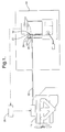
- a sensor 10 having a sensing element 12 is mounted within the fuel tank 14 of a vehicle and programmed to measure the DI number at each shut-off of the engine.
- the sensing element 12 is mounted within the fuel tank 14 so that the sensing element 12 is in communication with a flow of gasoline in the fuel line 16 when the engine 18 is running but remains above the maximum fuel level in the tank.
- a known volume of gasoline is drawn into the sensing element 12.
- the sensing element 12 is connected with a capacitance measuring circuit 20 to represent the volume of fuel in the sensing element 12.
- a heating element 22 and a temperature measuring circuit 24 are attached to the sensing element 12 to monitor the change in temperature of the sensing element 12 over time.
- the fuel within the sensing element 12 begins to evaporate.
- the temperature and capacitance of the sensing element 12 are monitored. Output from the capacitance circuit 20 and the temperature measurement circuit 24 are provided to the engine controller 26 to perform the DI calculations.
- the initial temperature read by the sensor 10 cannot be controlled, the sample amount is smaller and the measuring time is shorter than in the ASTM D86 test.
- the T 10 , T 50 , and T 90 show large differences compared with the ASTM D86 test. Therefore, correlations between the ASTM D86 test and results from the sensing element 12 for a given fuel must be established. Since the ASTM D86 test is the industrial standard, it is necessary to initially calibrate the measured results from the particular model of sensing element 12 selected for the vehicle make and model to match the results obtained from the standard.
- a calibration includes obtaining a first sample of fuel of known or unknown physical characteristics, and dividing the first sample into two containers wherein a first container contains a first known volume (100 mL) of the first sample from which the DI will be calculated according to the ASTM D86 test described above, and a second container contains a second known volume of the first fuel sample from which DI will be calculated using the sensor 10.
- the DI value for the fuel contained in the first sample is then calculated using the D86 test procedures which include obtaining values for T 10 , T 50 , and T 90 .
- the second container contains a volume of the first sample of fuel and is used to fill the sensing element 12 (step 30).
- the sensing element 12 has a known volume which depends on the physical characteristics of the particular sensing element 12.
- the volume of one sensing element used for testing had a range of 0.04-0.1 mL.
- the fuel contained in the sensing element is heated (step 32) by a controlled heating element 22 with the sensor 10 to provide normalized measured curves (Figure 4), wherein the normalized output (fuel level) is plotted versus sensor temperature (in degrees Celsius) (step 34).
- a known volume of a fuel sample is placed in the sensing element 12.
- the known volume is the same amount that will be drawn into the sensing element by the capillary effect on-board the vehicle.
- the heating (step 34) of the sensing element 12 is done in an environment similar to the on-board environment, since tank pressure and the thermal mass of the sensor 10 and its associated brackets can affect the vaporization rate of the fuel.
- the heating element 22 is actuated, the fuel is heated and vaporized, i.e. boiled off and volatilized.
- the fuel quantity and the fuel level in the sensing element 12 decreases as the heating time increases.
- the rate of fuel decrease will depend on the volatility, or the driveability index (DI) of the fuel.
- DI driveability index
- the fuel in the sensing element 12 can be emptied at much lower temperatures than the end of boiling point (EBP) measured in the D86 test.
- EBP end of boiling point
- a typical measured fuel EBP temperature is 200 ⁇ C. in the D86 test.
- the fuel in the sensing element 12 can be emptied at approximately 100 ⁇ C. Therefore, the sensor measurement can be completed in a reasonable time frame, shorter than three minutes, and be completed at a temperature below 120 ⁇ C.
- the output of the sensor 10 as a function of sensor temperature provides a normalized curve.
- the normalized curve defines the measured T xs as a sensor temperature at which x% of the fuel level has been vaporized. From the D86 test, the temperatures, T x are known, where x equals 10%, 50%, and 90% of the fuel level vaporized. Therefore, a linear equation can be calculated to correlate T xs to T x for each of the values of x equaling 10%, 50%, and 90% (step 36). For each of the x values of 10%, 50%, and 90% there will be a correlation factor or equation that can be used when an unknown fuel is measured by the sensor 10.
- the correlation factor or equation is stored in the engine controller 26 of the vehicle (step 38) and will use the measured T 10s , T 50s , and T 90s to calculate the needed T 10 , T 50 , and T 90 for the aforementioned driveability index (DI) calculation.
- the correlation factor or equation can be stored in the engine controller 26 in the form of equations or look up tables, or modified constants for the DI equation.
- DI driveability index
- Samples from the same three non-ethanol fuels are used in the heated sensor test either in a laboratory setting or on the vehicle.
- testing provides (50, 75.8, 95.4), (55.7, 81.2, 98.4), and (59.4, 85, 100.2) for the fuel samples which had DI of 1119, 1230, and 1294 values respectively.
- Figure 4 is a graph illustrating the normalized measured curves of the aforementioned example.
- the calculated driveability index (DI) numbers for the three fuel samples are 1120, 1226, and 1296 in comparison to the D86 tested numbers 1119, 1230, and 1294, respectively.
- the differences between the two test methods are -1, 4, and - 2, respectively.
- one method to calculate the fuel DI number on-board the vehicle is to store the correlation factor or equation (step 38) from a previously tested model of sensor 10 having known particular physical characteristics into the engine controller 26 of the vehicle.
- the fuel in the fuel tank 14 is then tested at predetermined conditions as discussed hereinafter to measure sensor temperature T xs versus x% vaporized output of fuel from the sensor 10 at a specific time.
- a known volume of fuel from the fuel tank 14 is drawn into the sensing element 12 (step 40). After a short delay period of a few seconds, the heating element 22 is activated to heat the sensing element 12 at a controlled rate (step 42).
- the capacitance measuring circuit 20 and the temperature measuring circuit 24 monitors the volume % of fuel vaporized versus the temperature (step 44), in particular, the temperatures (T 10s , T 50s , T 90s ) when the volume % of fuel vaporization is 10%, 50% and 90% respectively.
- the measurement of the T 10s , T 50s , and T 90s values will be applied to the stored correlation factors or equations to provide the T 10 , T 50 , and T 90 values used to calculate the DI number (step 46) of any non-ethanol fuel in a vehicle.
- the measured temperatures can be used in the DI equation after substitution of the correlation equations therein and simplification of the equation.
- DI s 6.82T 10s +9.87T 50s . +4.4388T 90s -392.43.
- the DI information may be necessary or preferable to calculate the DI information in as short of time and as low of a temperature as possible. Terminating the sensor heating at a smaller percentage of vaporized fuel, such as 70% instead of 90%, provides added advantages without significantly diminishing the correlation between the measured data of the sensing element 12 and the standard D86 test. If the sensor 10 is subject to lower temperatures the design of the sensor 10 is simplified. Further, if there is adequate amount of fuel in the sensing element 12 when the test is terminated, solid residue deposits on the sensor 10 are prevented. It is possible to terminate the sensor measurements when at least 50% but less than 90% of the fuel level has been vaporized.
- a correlation factor or equation can be calculated to extrapolate the measured T 70s to T 90 .
- the correlation equation can be substituted into the DI equation and the results simplified into a new DI s equation for use with these operating characteristics.
- T 90 3.1305T 70s + 52.173.
- correlation equations stored in the engine controller 26 for T 10 and T 50 would remain the same, but include instead of the previous correlation equation for T 90 would have the correlation equation between T 70s and T 90 .
- the calculated driveability index (DI) numbers for the fuel samples are 1120, 1225, and 1297 in comparison to the D86 test numbers of 1119, 1230, and 1294, respectively.
- the differences between the calculated DI numbers and the D86 numbers are -1, 5, and -3 respectively.
- the temperature at which 10% of the fuel level is vaporized can be calculated instead of reading directly from the sensor measurement.
- a quadratic equation is used to fit the portion where the normalized output ranges from 0% of the fuel level is vaporized to 20% of the fuel level is vaporized.
- the data of each curve represented in the graph of Figure 4 between the normalized output 1.0 at A and the normalized output 0.8 at B 1 , B 2 , and B 3 is fitted with a quadratic equation.
- the quadratic equation is solved to determine the fitted temperature T 10f after 10% of the fuel volume is vaporized.
- a linear equation is then used to correlate T 10f to T 10 .
- the new calculated T 10f value is used in place of the T 10s in the correlation equation to calculate T 10 .
- the results for T 10f are 50.2, 56, and 58.2 ⁇ C. in comparison to the results for T 10s of 50, 55.7, and 59.4 ⁇ C. respectively.
- the driveability index numbers are 1122, 1227, and 1289 in comparison to the D86 test results of 1119, 1230, and 1294 respectively.
- the differences between the two tests procedures are -3, 3, and 5, respectively. Solving for the fitted T 10f valve is advantageous in noisy electronic environments where the measured curve is not a clean curve, but includes many fluctuations.
- the starting of this measurement should follow the fuel loading without a long delay.
- the benefits of calculating a DI number on-board the vehicle includes a decrease in HC and CO emissions while improving fuel economy. Further, costly hardware, such as the AIR pump or the precious metal in the catalytic converter, could be eliminated and be replaced with the low-cost sensor. In addition, new EPA regulations would be easier to meet.
Landscapes
- Engineering & Computer Science (AREA)
- Chemical & Material Sciences (AREA)
- Oil, Petroleum & Natural Gas (AREA)
- Combustion & Propulsion (AREA)
- Mechanical Engineering (AREA)
- General Engineering & Computer Science (AREA)
- Health & Medical Sciences (AREA)
- Life Sciences & Earth Sciences (AREA)
- Food Science & Technology (AREA)
- General Chemical & Material Sciences (AREA)
- Chemical Kinetics & Catalysis (AREA)
- Medicinal Chemistry (AREA)
- Physics & Mathematics (AREA)
- Analytical Chemistry (AREA)
- Biochemistry (AREA)
- General Health & Medical Sciences (AREA)
- General Physics & Mathematics (AREA)
- Immunology (AREA)
- Pathology (AREA)
- Combined Controls Of Internal Combustion Engines (AREA)
Abstract
Description
where the feedstocks are known, it has not been accepted as an accurate way to characterize the DI of finished gasoline in the field.
where x equals 10%, 50%, and 90% of the fuel level vaporized. Therefore, a linear equation can be calculated to correlate Txs to Tx for each of the values of x equaling 10%, 50%, and 90% (step 36). For each of the x values of 10%, 50%, and 90% there will be a correlation factor or equation that can be used when an unknown fuel is measured by the sensor 10. The correlation factor or equation is stored in the engine controller 26 of the vehicle (step 38) and will use the measured T10s, T50s, and T90s to calculate the needed T10, T50, and T90 for the aforementioned driveability index (DI) calculation. The correlation factor or equation can be stored in the engine controller 26 in the form of equations or look up tables, or modified constants for the DI equation.
Claims (14)
- A method for calculating a fuel driveability index (DI) value on-board a vehicle having a fuel tank (14) and an engine controller (26), said method comprising the steps of:holding a known volume of fuel from the fuel tank in a sensor (40);heating the sensor and volume of fuel therein (42);measuring temperatures of the sensor relative to the volume of fuel remaining in the sensor as the sensor is heating(44); andcalculating a DI value from the measured T10, T50, and T90 values (46).
- The method of claim 1 wherein the step of heating the sensor (42) occurs after the vehicle is turned off.
- The method of claim 1, wherein the step of measuring temperatures (44) terminates when the volume of fuel in the sensor is less than 90% vaporized.
- The method of claim 3, wherein the measuring of temperatures (44) terminates at a predetermined percentage of output volume providing a termination temperature is used to calculate the DI value.
- The method of claim 1, wherein the step of measuring the temperatures (44) includes the steps of:measuring the temperatures of the sensor when the output volume of the sensor ranges from 0% to 20% vaporization of the fuel volume; andfitting a quadratic equation to the ranges to solve for a T10f value.
- The method of claim 5, wherein the step of applying at least some of the measured temperatures includes the step of applying the T10f value to the correlation equation to solve for T10.
- The method of claim 1, wherein the correlation equations are stored in the engine controller (26).
- The method of claim 1, further comprising the steps of:prior to applying at least some of the measured temperatures to correlation equations, running a D86 standard test with a volume of fuel and solving for temperatures (T10, T50, T90) when the volume % of the fuel vaporizes is 10%, 50% and 90% respectively (28);heating a sensor with a known volume of the fuel therein (32);measuring for sensor temperatures relative to the % volume of fuel vaporized from the sensor (34); andcorrelating predetermined measured sensor temperatures to the T10, T50, and T90 to provide correlation measurements (36).
- The method of claim 8, further comprising the step of:storing said correlation equations into the engine controller (38).
- The method of claim 1, further comprising the step of storing a modified DI equation in the engine controller (38).
- A system for calculating a fuel driveability (DI) value on-board a vehicle having a fuel tank and an engine controller, the system comprising:means for holding (12) a known volume of fuel from the fuel tank (14) in a sensor (10);means for heating (22) the sensor (10) and the volume of fuel therein;means for measuring temperatures (24) of the sensor (10) relative to the volume of fuel remaining in the sensor as the sensor is heating; andmeans for calculating a DI value from the measured T10, T50 and T90 values.
- The system of claim 11, wherein the sensor (10) is positioned in the fuel tank (14).
- The system of claim 11, wherein means for calculating a DI value includes a modified DI equation stored in the engine controller (26).
- A system for calculating a fuel driveability (DI) value for a vehicle, the system comprising:a standard test for calculating a DI value of a sample of fuel of a known volume by measuring the volume of fuel versus temperature as the fuel is heated;a sensor (10) for storing another known volume of the sample of fuel;means for heating (22) the sensor (10) and the volume of fuel therein;means for measuring the volume (20) of fuel in the sensor (10) versus the temperature (24) of the sample fuel; andmeans for correlating the measured temperature and volume of fuel in the sensor (10) with the measured temperature and volume of fuel in the standard test.
Applications Claiming Priority (2)
| Application Number | Priority Date | Filing Date | Title |
|---|---|---|---|
| US10/117,833 US6712503B2 (en) | 2002-04-08 | 2002-04-08 | Method to calculate fuel DI number from a measured curve |
| US117833 | 2002-04-08 |
Publications (3)
| Publication Number | Publication Date |
|---|---|
| EP1353177A2 true EP1353177A2 (en) | 2003-10-15 |
| EP1353177A3 EP1353177A3 (en) | 2004-12-08 |
| EP1353177B1 EP1353177B1 (en) | 2006-11-02 |
Family
ID=28453956
Family Applications (1)
| Application Number | Title | Priority Date | Filing Date |
|---|---|---|---|
| EP03075858A Expired - Lifetime EP1353177B1 (en) | 2002-04-08 | 2003-03-24 | A method to calculate fuel DI number from a measured curve |
Country Status (3)
| Country | Link |
|---|---|
| US (1) | US6712503B2 (en) |
| EP (1) | EP1353177B1 (en) |
| DE (1) | DE60309370T2 (en) |
Cited By (1)
| Publication number | Priority date | Publication date | Assignee | Title |
|---|---|---|---|---|
| WO2011053905A1 (en) * | 2009-10-30 | 2011-05-05 | Cummins Inc. | Engine control techniques to account for fuel effects |
Families Citing this family (8)
| Publication number | Priority date | Publication date | Assignee | Title |
|---|---|---|---|---|
| JP4017989B2 (en) * | 2001-05-17 | 2007-12-05 | シーメンス ヴィディーオー オートモティヴ コーポレイション | Fuel sensor for vehicle |
| US6827484B2 (en) * | 2002-07-09 | 2004-12-07 | Charles Y. Tsang | Cloud point monitoring device |
| US6826950B2 (en) * | 2003-01-31 | 2004-12-07 | Delphi Technologies, Inc. | Fuel quality sensor associated with a housing in fuel delivery system |
| DE102004046780B4 (en) * | 2004-09-27 | 2007-04-26 | Siemens Ag | Method for functional tester of a level sensor |
| US8000880B2 (en) * | 2008-04-16 | 2011-08-16 | GM Global Technology Operations LLC | Fuel quality detection using torque and engine speed |
| US7980342B2 (en) * | 2008-06-27 | 2011-07-19 | Ford Global Technologies, Llc | Plug-in hybrid electric vehicle |
| US8177006B2 (en) | 2009-05-28 | 2012-05-15 | Ford Global Technologies, Llc | Plug-in hybrid electric vehicle |
| US8849545B2 (en) | 2011-03-07 | 2014-09-30 | GM Global Technology Operations LLC | Controlling fuel injection based on fuel volatility |
Family Cites Families (11)
| Publication number | Priority date | Publication date | Assignee | Title |
|---|---|---|---|---|
| US3379202A (en) * | 1965-09-30 | 1968-04-23 | Union Oil Co | Continuous gasoline warmup factor analyzer and method of control |
| US5225679A (en) * | 1992-01-24 | 1993-07-06 | Boston Advanced Technologies, Inc. | Methods and apparatus for determining hydrocarbon fuel properties |
| JPH0617693A (en) * | 1992-04-17 | 1994-01-25 | Nippondenso Co Ltd | Electronic control system for internal combustion engine |
| US5750995A (en) * | 1996-02-16 | 1998-05-12 | Boston Advanced Technologies, Inc. | Methods and devices for fuel characterization and optimal fuel identification on-site at a fuel delivery dispenser |
| US5569922A (en) * | 1995-07-26 | 1996-10-29 | Boston Advanced Technologies, Inc. | Portable fuel analyzer for the diagnosis of fuel-related problems on-site at the vehicle service bay |
| US5949695A (en) * | 1997-01-10 | 1999-09-07 | Harris Corporation | Interpolator using a plurality of polynomial equations and associated methods |
| US6295808B1 (en) * | 1999-06-29 | 2001-10-02 | Hereaus Electro-Nite International N.V. | High driveability index fuel detection by exhaust gas temperature measurement |
| US6360726B1 (en) * | 2000-07-31 | 2002-03-26 | General Motors Corporation | Fuel volatility detection and compensation during cold engine start |
| US6360587B1 (en) | 2000-08-10 | 2002-03-26 | Delphi Technologies, Inc. | Pre-ignition detector |
| WO2002018935A1 (en) * | 2000-08-29 | 2002-03-07 | Epiq Sensor-Nite N.V. | High driveability index fuel detection by exhaust gas temperature measurement |
| US6520166B1 (en) | 2001-10-05 | 2003-02-18 | Delphi Technologies, Inc. | Method of identifying engine cylinder combustion sequence based on combustion quality |
-
2002
- 2002-04-08 US US10/117,833 patent/US6712503B2/en not_active Expired - Fee Related
-
2003
- 2003-03-24 EP EP03075858A patent/EP1353177B1/en not_active Expired - Lifetime
- 2003-03-24 DE DE60309370T patent/DE60309370T2/en not_active Expired - Fee Related
Cited By (2)
| Publication number | Priority date | Publication date | Assignee | Title |
|---|---|---|---|---|
| WO2011053905A1 (en) * | 2009-10-30 | 2011-05-05 | Cummins Inc. | Engine control techniques to account for fuel effects |
| US8813690B2 (en) | 2009-10-30 | 2014-08-26 | Cummins Inc. | Engine control techniques to account for fuel effects |
Also Published As
| Publication number | Publication date |
|---|---|
| DE60309370T2 (en) | 2007-08-30 |
| EP1353177B1 (en) | 2006-11-02 |
| EP1353177A3 (en) | 2004-12-08 |
| DE60309370D1 (en) | 2006-12-14 |
| US6712503B2 (en) | 2004-03-30 |
| US20030189969A1 (en) | 2003-10-09 |
Similar Documents
| Publication | Publication Date | Title |
|---|---|---|
| Aquino | Transient A/F control characteristics of the 5 liter central fuel injection engine | |
| US8733298B2 (en) | Method and apparatus for operating a compression ignition engine | |
| US20090178474A1 (en) | Fuel composition estimation and control of fuel injection | |
| US6712503B2 (en) | Method to calculate fuel DI number from a measured curve | |
| US6880392B2 (en) | Method and apparatus for determining an approximation for fuel volatility on-board a vehicle | |
| CN101346539A (en) | Method for onboard determination of fuel volatility | |
| US9841412B2 (en) | Method and system for determining the volatility of a fuel | |
| EP0984148B1 (en) | Fuel metering system and method | |
| US20080213914A1 (en) | Method and system for measuring ron and mon values for light distillates | |
| Wu et al. | A reduced PM index for evaluating the effect of fuel properties on the particulate matter emissions from gasoline vehicles | |
| US7220386B2 (en) | On-board fuel properties measurement for engine management | |
| US6564624B2 (en) | Fuel driveability index sensor and method | |
| Broatch et al. | Measurement of hydrocarbon and carbon monoxide emissions during the starting of automotive DI diesel engines | |
| Thomas et al. | Effects of High Octane Ethanol Blends on Four Legacy Flex-Fuel Vehicles, and a Turbocharged GDI Vehicle | |
| de Melo et al. | In cylinder pressure curve and combustion parameters variability with ethanol addition | |
| Artmann et al. | A new measurement technique for online oil dilution measurement | |
| Irimescu | Back-pressure and fuel type effects on exhaust gas oxygen sensor readings for a single cylinder spark ignition engine running on gasoline and ethanol | |
| Mäder et al. | Influences of entrainers to engine oil to improve the drag-out of biodiesel–Experiments and simulations | |
| Lee et al. | An on-vehicle fuel driveability index sensor | |
| da Silva et al. | Non-invasive fuel consumption measurement for internal combustion engines based on Otto cycle | |
| Bair | Ignition quality and composition of fuel volatile fraction: Effects on diesel combustion | |
| Mason et al. | On the Validity of Steady-State Gasoline Engine Characterization Methodology for Generation of Optimal Calibrations Used in Real World Driving | |
| Graßmeyer et al. | Evaluation of Different Gasoline Formulations on a High-Performance Engine | |
| Arters et al. | Effects of gasoline driveability index, ethanol and intake valve deposits on engine performance in a dynamometer-based cold start and warmup procedure | |
| Wang et al. | A physical model for the interdigitated fuel drivability index sensor |
Legal Events
| Date | Code | Title | Description |
|---|---|---|---|
| PUAI | Public reference made under article 153(3) epc to a published international application that has entered the european phase |
Free format text: ORIGINAL CODE: 0009012 |
|
| AK | Designated contracting states |
Kind code of ref document: A2 Designated state(s): AT BE BG CH CY CZ DE DK EE ES FI FR GB GR HU IE IT LI LU MC NL PT RO SE SI SK TR |
|
| AX | Request for extension of the european patent |
Extension state: AL LT LV MK |
|
| PUAL | Search report despatched |
Free format text: ORIGINAL CODE: 0009013 |
|
| AK | Designated contracting states |
Kind code of ref document: A3 Designated state(s): AT BE BG CH CY CZ DE DK EE ES FI FR GB GR HU IE IT LI LU MC NL PT RO SE SI SK TR |
|
| AX | Request for extension of the european patent |
Extension state: AL LT LV MK |
|
| RIC1 | Information provided on ipc code assigned before grant |
Ipc: 7G 01N 33/28 B Ipc: 7G 01N 33/22 A |
|
| 17P | Request for examination filed |
Effective date: 20050608 |
|
| AKX | Designation fees paid |
Designated state(s): DE FR GB |
|
| GRAP | Despatch of communication of intention to grant a patent |
Free format text: ORIGINAL CODE: EPIDOSNIGR1 |
|
| GRAS | Grant fee paid |
Free format text: ORIGINAL CODE: EPIDOSNIGR3 |
|
| GRAA | (expected) grant |
Free format text: ORIGINAL CODE: 0009210 |
|
| AK | Designated contracting states |
Kind code of ref document: B1 Designated state(s): DE FR GB |
|
| REG | Reference to a national code |
Ref country code: GB Ref legal event code: FG4D |
|
| REF | Corresponds to: |
Ref document number: 60309370 Country of ref document: DE Date of ref document: 20061214 Kind code of ref document: P |
|
| PGFP | Annual fee paid to national office [announced via postgrant information from national office to epo] |
Ref country code: DE Payment date: 20070322 Year of fee payment: 5 |
|
| ET | Fr: translation filed | ||
| PLBE | No opposition filed within time limit |
Free format text: ORIGINAL CODE: 0009261 |
|
| STAA | Information on the status of an ep patent application or granted ep patent |
Free format text: STATUS: NO OPPOSITION FILED WITHIN TIME LIMIT |
|
| 26N | No opposition filed |
Effective date: 20070803 |
|
| GBPC | Gb: european patent ceased through non-payment of renewal fee |
Effective date: 20070324 |
|
| PG25 | Lapsed in a contracting state [announced via postgrant information from national office to epo] |
Ref country code: GB Free format text: LAPSE BECAUSE OF NON-PAYMENT OF DUE FEES Effective date: 20070324 |
|
| PGFP | Annual fee paid to national office [announced via postgrant information from national office to epo] |
Ref country code: FR Payment date: 20070308 Year of fee payment: 5 |
|
| REG | Reference to a national code |
Ref country code: FR Ref legal event code: ST Effective date: 20081125 |
|
| PG25 | Lapsed in a contracting state [announced via postgrant information from national office to epo] |
Ref country code: DE Free format text: LAPSE BECAUSE OF NON-PAYMENT OF DUE FEES Effective date: 20081001 |
|
| PG25 | Lapsed in a contracting state [announced via postgrant information from national office to epo] |
Ref country code: FR Free format text: LAPSE BECAUSE OF NON-PAYMENT OF DUE FEES Effective date: 20080331 |