EP1353175A2 - Piezoelectric sensor and method for manufacturing the same - Google Patents
Piezoelectric sensor and method for manufacturing the same Download PDFInfo
- Publication number
- EP1353175A2 EP1353175A2 EP03007959A EP03007959A EP1353175A2 EP 1353175 A2 EP1353175 A2 EP 1353175A2 EP 03007959 A EP03007959 A EP 03007959A EP 03007959 A EP03007959 A EP 03007959A EP 1353175 A2 EP1353175 A2 EP 1353175A2
- Authority
- EP
- European Patent Office
- Prior art keywords
- measuring chamber
- body portion
- casing
- sensor
- ultrasonic waves
- Prior art date
- Legal status (The legal status is an assumption and is not a legal conclusion. Google has not performed a legal analysis and makes no representation as to the accuracy of the status listed.)
- Withdrawn
Links
Images







Classifications
-
- G—PHYSICS
- G01—MEASURING; TESTING
- G01N—INVESTIGATING OR ANALYSING MATERIALS BY DETERMINING THEIR CHEMICAL OR PHYSICAL PROPERTIES
- G01N29/00—Investigating or analysing materials by the use of ultrasonic, sonic or infrasonic waves; Visualisation of the interior of objects by transmitting ultrasonic or sonic waves through the object
- G01N29/22—Details, e.g. general constructional or apparatus details
- G01N29/223—Supports, positioning or alignment in fixed situation
-
- G—PHYSICS
- G01—MEASURING; TESTING
- G01N—INVESTIGATING OR ANALYSING MATERIALS BY DETERMINING THEIR CHEMICAL OR PHYSICAL PROPERTIES
- G01N2291/00—Indexing codes associated with group G01N29/00
- G01N2291/02—Indexing codes associated with the analysed material
- G01N2291/021—Gases
-
- G—PHYSICS
- G01—MEASURING; TESTING
- G01N—INVESTIGATING OR ANALYSING MATERIALS BY DETERMINING THEIR CHEMICAL OR PHYSICAL PROPERTIES
- G01N2291/00—Indexing codes associated with group G01N29/00
- G01N2291/02—Indexing codes associated with the analysed material
- G01N2291/028—Material parameters
- G01N2291/02809—Concentration of a compound, e.g. measured by a surface mass change
-
- G—PHYSICS
- G01—MEASURING; TESTING
- G01N—INVESTIGATING OR ANALYSING MATERIALS BY DETERMINING THEIR CHEMICAL OR PHYSICAL PROPERTIES
- G01N2291/00—Indexing codes associated with group G01N29/00
- G01N2291/02—Indexing codes associated with the analysed material
- G01N2291/028—Material parameters
- G01N2291/02818—Density, viscosity
-
- G—PHYSICS
- G01—MEASURING; TESTING
- G01N—INVESTIGATING OR ANALYSING MATERIALS BY DETERMINING THEIR CHEMICAL OR PHYSICAL PROPERTIES
- G01N2291/00—Indexing codes associated with group G01N29/00
- G01N2291/02—Indexing codes associated with the analysed material
- G01N2291/028—Material parameters
- G01N2291/02881—Temperature
Definitions
- the present invention relates to a sensor configured such that an element casing, housing an element for transmitting and receiving ultrasonic waves and electric signals, is attached to a measuring chamber in which an object to be measured by use of ultrasonic waves is present, as well as to a method for manufacturing the sensor.
- an assembly of an element for transmitting and receiving ultrasonic waves and electric signals and a casing housing the element has been used as a sensor or an ultrasonic-wave generator.
- Ultrasonic waves propagate through various media. Since the propagation of ultrasonic waves is influenced by properties of a medium, such as concentration, thickness, and temperature, ultrasonic waves are utilized for sensing such properties.
- a medium such as concentration, thickness, and temperature
- ultrasonic waves are utilized for sensing such properties.
- an ultrasonic-wave generator that faces a flow path is used for measuring the concentration, temperature, or humidity of a gas present in the flow path.
- Such a gas sensor electrically processes a signal emitted from a detecting element and outputs an electric signal corresponding to a property of the gas.
- Examples of such a gas sensor include a gas concentration sensor used in transportation equipment on which an internal combustion engine is mounted, such as an automobile, for detecting the concentration of gasoline or light oil through utilization of variation in propagation speed of ultrasonic waves.
- a gas concentration sensor is disposed in, for example, a purge line extending between a canister mounted on an automobile and an intake pipe of an internal combustion engine of the automobile, and is configured such that an evaporated fuel gas which contains gasoline flows through a flow path of a predetermined volume formed therein.
- the concentration of gasoline vapor varies, the speed of ultrasonic waves propagating through the medium varies.
- An ultrasonic receiver detects this variation of speed and conducts signal processing so as to output a signal corresponding to the gasoline concentration.
- time required for an ultrasonic wave transmitted from a transmitter to propagate over a predetermined distance and reach a receiver is measured, and the gasoline concentration is obtained from the measured time.
- attachment of this gas sensor to a measuring chamber in a fixed condition has involved a phenomenon such that ultrasonic waves propagate through an outer wall which defines the measuring chamber, and reach the detecting element.
- Some cases where an element for transmitting ultrasonic waves is housed in a sensor have involved a phenomenon such that ultrasonic waves transmitted from the element are reflected from a joint between the sensor and a measuring chamber, and the thus-reflected waves are received by a receiving element and act as noise in measurement.
- An object of the present invention is to solve the above-mentioned problems and to provide a sensor which is unlikely to pick up noise stemming from detouring or reflection of ultrasonic waves.
- This sensor is configured such that the element casing is attached to the measuring chamber via the flange portion thereof.
- the element housed in the element casing is attached to the first end of the body portion, and the flange portion is integrated with the second end of the body portion located in opposition to the first end, to which the element housed in the body portion is attached. Therefore, as viewed from the element for transmitting and receiving ultrasonic waves and electric signals, the far side of the element casing is fixedly attached to the measuring chamber; thus, the element is not susceptible to the influence of ultrasonic waves reflected from the fixation portion or detouring ultrasonic waves on the side where measurement is performed.
- the body portion of the element casing can be molded from a synthetic resin.
- the flange portion can be readily formed integrally with the body portion.
- the element casing can be configured such that the body portion is tubular and such that the first end of the body portion is sealed with a sealing member.
- the element may be bonded to the sealing member directly or via a member that aids transmission of ultrasonic waves.
- the tubular body portion can be filled with resin while housing the element. Employment of this configuration facilitates transmission and reception of ultrasonic waves between the sensor and an external element and can enhance reliability of the element casing.
- a portion of the measuring chamber to which the element casing is attached can be one of inner walls which define the measuring chamber.
- the inside diameter of the portion of the measuring chamber to which the element casing is attached is made greater than the outside diameter of the element casing.
- the inside diameter is 2 mm or more greater than the outside diameter. Employment of such a diametral difference of 2 mm or more provides an average clearance of 1 mm, whereby ultrasonic reverberations in the element are reduced, and foreign matter or the like is unlikely to be collected in the clearance.
- this sensor no particular limitation is imposed on an object to be measured, or on a medium such as gas or liquid.
- this sensor can be configured as a gas concentration sensor such that the object to be measured is gas and in such a manner as to comprise a detecting portion for detecting the condition of transmission of ultrasonic waves by means of an electric signal received from the element and determining the concentration of the gas from the detected condition. Assuming a simple structure, this gas sensor can accurately measure the concentration of gas in a non-contacting manner.
- an ultrasonic transmitter and an ultrasonic receiver may be provided separately.
- a single element can serve as an ultrasonic transmitter-receiver.
- the sensor can be configured such that the element casing is provided at a first end of the measuring chamber in which an object to be measured is present, and a reflective portion for reflecting ultrasonic waves is provided at a second end of the measuring chamber, and such that ultrasonic waves which are transmitted from the element casing and then reflected from the reflective portion are received by the same element housed in the element casing.
- the concentration of gas can be determined from the measured time. Employment of a transmitter-receiver element simplifies the overall configuration of the sensor.
- the flange portion and the body portion can be embodied in various relational forms.
- the outside diameter of the flange portion is greater than that of the body portion.
- the flange portion comprises a portion having an outside diameter smaller than that of the body portion and integrated with a central part of the second end of the body portion.
- the flange portion is fixedly attached to the measuring chamber at a position located distantly from the element, in order to enhance noise resistance.
- a second aspect of the present invention provides a sensor comprising an element for transmitting and receiving ultrasonic waves and electric signals, an element casing housing the element, and a measuring chamber, the element casing being provided in the measuring chamber, and an object to be measured by use of ultrasonic waves being present in the measuring chamber, wherein the element casing comprises a tubular portion for housing the element, the tubular portion and the measuring chamber being integrally formed from resin;
- this sensor is configured such that the element casing is not formed as a separate member, but includes the tubular portion which houses the element and is formed from resin integrally with the measuring chamber.
- the tubular portion is integrated with the measuring chamber at a position located a predetermined distance away from a region of the measuring chamber in which the object is present.
- the element is housed in the tubular portion at an end thereof located on the side toward the measuring chamber, and the end of the tubular portion is sealed.
- the element for transmitting and receiving ultrasonic waves and electric signals and the tubular portion housing the element are joined together at a position located away from the measuring chamber, whereby the element is not susceptible to the influence of reflected ultrasonic waves and detouring ultrasonic waves.
- the present invention further provides a method for manufacturing a sensor comprising an element for transmitting and receiving ultrasonic waves and electric signals, an element casing housing the element, and a measuring chamber, an object to be measured by use of ultrasonic waves being present in the measuring chamber, the method comprising the steps of:
- This method for manufacturing a sensor allows the flange portion to be readily attached to the measuring chamber in a fixed condition while the element casing which houses the element faces the measuring chamber.
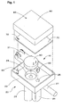
- FIG. 1 is an exploded perspective view of a gas sensor according to an embodiment of the present invention.
- This gas sensor 10 determines the concentration of gasoline vapor through utilization of a phenomenon in which the propagation speed of ultrasonic waves varies with gas concentration.
- This gas sensor is disposed in, for example, a path for purging gasoline to an intake path from a canister mounted on a vehicle powered by an internal combustion engine, and is used to determine the concentration of gasoline to be purged.
- the gas sensor 10 includes a flow path formation member 20 which forms a flow path through which gas whose concentration is to be determined flows; a detecting-element assembly 40 housed in a housing portion 22 formed integrally with the flow path formation member 20; a thermistor 60 for detecting the temperature of gas flowing through the flow path; an electronic circuit board 70 disposed above the detecting-element assembly 40; and a metal casing 80 fitted in the housing portion 22.
- the detecting-element assembly 40 is fixedly fitted in a mounting recess 24 formed on the housing portion 22, through ultrasonic welding.
- the thermistor 60 is fixedly inserted in a mounting hole 25.
- the detecting-element assembly 40 and the thermistor 60 have terminals for transmitting and receiving electric signals. These terminals are inserted into corresponding connection holes formed in the electronic circuit board 70, followed by soldering.
- the gas sensor 10 is manufactured in the following manner. After the detecting-element assembly 40 and the thermistor 60 are fixedly attached to the housing portion 22, the electronic circuit board 70 for processing signals is mounted in place. The casing 80 is fitted into the housing portion 22. Then, the thus-formed assembly is molded with resin such as urethane resin. The process for manufacturing the gas sensor 10 will be described later in detail in (G).
- the flow path formation member 20 of the gas sensor 10 is molded from a synthetic resin which contains glass filler.
- the tensile modulus of the flow path formation member 20 is adjusted so as to be suited for use in a gas sensor.
- the flow path formation member 20 includes the housing portion 22 which is provided at an upper portion thereof so as to house the detecting-element assembly 40, and a flow path which is formed underneath the housing portion 22 and allows the passage of an object gas of measurement.
- the flow path includes an introduction path 27 for introducing gas containing gasoline vapor into the gas sensor 10; a measuring chamber 28 in which the concentration of gasoline in the gas is detected by means of ultrasonic waves; and a bypass 29 for allowing the gas to bypass the measuring chamber 28.
- the measuring chamber 28 is located substantially under the detecting-element assembly 40, and the bypass 29 is located substantially under the thermistor 60.
- Fig. 2 is a sectional view of the gas sensor 10 taken along a plane which includes the axis of the introduction path 27 and the axis of the detecting-element assembly 40.
- the gas sensor 10 is finally covered with resin (e.g., urethane resin) through molding.
- resin e.g., urethane resin
- Fig. 2 does not show the molding resin which covers the entire gas sensor 10.
- the interior of the flow path formation member 20 is divided into the introduction path 27, the measuring chamber 28, and the bypass 29.
- the introduction path 27 communicates with the bypass 29 perpendicularly and with the measuring chamber 28 via an inlet hole 32.
- An outlet 34 is formed at a lower end portion of the bypass 29.
- a gas which contains gasoline vapor and is introduced through the introduction path 27 is discharged from the outlet 34.
- the discharged gas is led to an intake path of an internal combustion engine through an unillustrated hose.
- the mounting hole 25 in which the thermistor 60 is mounted is formed at an end portion of the bypass 29 opposite the outlet 34. Therefore, the thermistor 60 detects the temperature of a gas introduced through the introduction path 27, according to a predetermined law.
- An upper portion of the measuring chamber 28 communicates with the recess 24 in which the detecting-element assembly 40 is mounted.
- a reflective portion 33 for reflecting ultrasonic waves is formed at a lower portion of the measuring chamber 28. The function of the reflective portion 33 will be described later.
- the reflective portion 33 is raised by a predetermined height (several millimeters in the present embodiment) from a bottom portion of the measuring chamber 28.
- a groove around the reflective portion 33 is connected to the bypass 29 via a discharge path 35 which communicates with the bottom portion of the measuring chamber 28.
- the discharge path 35 is provided at the bottom portion of the measuring chamber 28, water droplets and oil droplets formed through condensation of water vapor and gasoline vapor in the measuring chamber 28 are drained through the discharge path 35.
- the groove is sloped downward toward the discharge path 35.
- a metal plate 36 is embedded in the housing portion 22 through insert molding.
- the metal plate 36 is embedded in the bottom of the housing portion 22 while assuming a shape resembling the shape of the bottom.
- the metal plate 36 has a cut-and-raised portion 83 for establishing electrical connection. As shown in Fig. 1, after insert molding, the cut-and-raised portion 83 is in a condition to stand within the interior of the housing portion 22.
- the cut-and-raised portion 83 is inserted into a connection hole 72 formed in the board 70.
- a land connected to a grounding line is provided around the connection hole 72.
- the cut-and-raised portion 83 is soldered to the land.
- a protrusion for use with a terminal is provided at one of four inside comers of the housing portion 22 adjacent to the cut-and-raised portion 83 and is also used as a support base for supporting the electronic circuit board 70 which is placed thereon.
- a connector 31 for transmitting and receiving electric signals is formed at the outside of the protrusion.
- the terminals of the connector 31 extend through the wall of the housing portion 22 at the position corresponding to the protrusion.
- the connector 31 has three terminals on the inlet side thereof. Two opposite terminals of the three are the GND terminal and the Vcc terminal which are connected to power lines (ground and DC voltage) for supplying power to the gas sensor 10 from the outside, and the central terminal is the SGNL terminal connected to a signal output line of the gas sensor 10 (see Fig.
- Fig. 3 is a sectional view showing the structure of the detecting-element assembly 40.
- the detecting-element assembly 40 assumes a disk-like shape, for the following reason: after a piezoelectric element 51 and other elements, which will be described later, are housed in an element casing 42 having a flange portion 41 and formed from a synthetic resin, the element casing 42 is filled with urethane resin.
- the flange portion 41 of the element casing 42 has a diameter greater than that of the recess 24 formed in the housing portion 22.
- a casing body portion 43 extending downward from the flange portion 41 has a diameter smaller than that of the recess 24.
- the casing body portion 43 opens downward, and a stepped portion 46 is formed on an end face 45 of the casing body portion 43 along the outer edge thereof.
- a circular protective film 48 formed from a gasoline-resistant material is bonded to the end face 45 in such a manner as to be located inside the stepped portion 46. Since the stepped portion 46 is shaped in such a manner as to render the surface tension of liquid greater than that at a central portion of the protective film 48, liquid preferentially adheres thereto.
- the stepped portion 46 is of such a simple structure as to extend from the lower end of the casing body portion 43. The stepped portion 46 protrudes along the entire circumference of the end face 45.
- the stepped portion 46 may protrude along such a partial circumference as to provide a lyophilic property.
- the stepped portion 46 surrounds the circumferential edge of the protective film 48 such that the circumferential edge is not exposed to the outside.
- the circumferential edge of the protective film 48 is not susceptible to a large force.
- the circumferential edge of the protective film 48 is not susceptible to a large force induced by a gas flow. Therefore, the protective film 48 is unlikely to come off, thereby preventing a problem of direct exposure of the interior of the detecting-element assembly 40 to a gas flow and a deterioration in the characteristics of the piezoelectric element 51.
- the end face 45 formed on the inside of the stepped portion 46 is formed such that the difference between its outside diameter and the diameter of the protective film 48 is very small.
- the stepped portion 46 serves as a guide for positioning the protective film 48, whereby the center misalignment between the protective film 48 and the element casing 42 can fall within a predetermined range of variation. Therefore, a positioning jig for use in attaching the protective film 48 to the open lower end of the element casing 42 is unnecessary, thereby facilitating work.
- a separate member to be attached to the open lower end of the element casing 42 may be employed so as to hold the protective film 48 between the member and the lower end of the element casing 42.
- a columnar, acoustic matching plate 50 is bonded to the protective film 48 at the center thereof.
- the piezoelectric element 51 which is an ultrasonic generation element, is bonded to the upper surface of the acoustic matching plate 50.
- the acoustic matching plate 50 is adapted to efficiently transmit vibrations of the piezoelectric element 51 into the air (the measuring chamber 28 in the present embodiment) via the protective film 48. Since sonic waves and ultrasonic waves tend to be reflected where the density of a medium differs, the piezoelectric element 51 is not directly bonded to the protective film 48, but is bonded via the acoustic matching plate 50, so that vibrations of the piezoelectric element 51 are efficiently transmitted as ultrasonic waves into the measuring chamber 28.
- the acoustic matching plate 50 is formed such that a number of small glass beads are solidified together by means of an epoxy resin.
- a tubular member 52 is disposed in such a manner as to surround the acoustic matching plate 50 and the piezoelectric element 51.
- the tubular member 52 is formed in the following manner.
- a polyethylene terephthalate film 52a and a copper foil 52c are bonded together via a bonding layer 52b.
- the resultant laminate is rolled into a cylindrical shape such that the copper foil 52c comes inside, and mating ends are bonded together in an overlapped condition.
- the tubular member 52 Since the inside diameter of the tubular member 52 is substantially equal to the outside diameter of the acoustic matching plate 50, the tubular member 52 comes in close contact with the outer circumferential surface of the acoustic matching plate 50. However, these two members are not bonded together.
- the piezoelectric element 51 is a piezoelectric or electrostrictive element formed into a columnar shape. The element is cut out while the lattice orientation is adjusted such that, when voltage is applied to electrodes formed on the axially upper and lower faces of the element, deformation arises only along the axial direction. As will be described later, in the present embodiment, the piezoelectric element 51 functions as a transmitter for transmitting ultrasonic waves into the measuring chamber 28 and as a receiver for receiving ultrasonic waves and outputting electric signals. As a matter of course, a gas sensor may be formed such that a transmitting element and a receiving element are provided separately.
- the piezoelectric element 51 can be of piezoelectric ceramic or crystal such as quartz as appropriate. Electrodes are not illustrated, but may be formed on the upper and lower faces of the piezoelectric element 51 through vapor deposition or a like process or through bonding of thin metal plates.
- the element casing 42 has a section whose shape resembles the inverted letter "L."
- the inner surface of the element casing 42 is tapered at a predetermined angle (about 11 degrees in the present embodiment) with respect to the vertical plane. Therefore, the wall of the casing body portion 43 increases in thickness downward; i.e., toward the protective film 48.
- the casing body portion 43 of the element casing 42 is formed such that its wall merged with the flange portion 41 is thin to thereby provide flexibility and such that its lower end face provides a sufficient area for bonding the protective film 48 thereto.
- the element casing 42 is formed into a substantially cylindrical shape except that portions where terminals 55a and 55b are embedded protrude inward.
- protrusions 56a and 56b have the terminals 55a and 55b embedded therein through insert molding.
- the terminals 55a and 55 are each bent into a shape resembling the letter "L.”
- the lower end of each of the terminals 55a and 55b protrudes inward from the inner surface of the casing body portion 43.
- Lead wires 54a and 54b are soldered to the lower ends of the terminals 55a and 55b, respectively.
- urethane resin is filled into the element casing 42.
- the upper ends of the terminals 55a and 55b protrude upward from the upper surface of the element casing 42.
- the element casing 42 has a circumferential protrusion 59 formed on the lower surface of the flange portion 41 substantially at the center.
- the protrusion 59 is melted through ultrasonic welding so as to fixedly join the flange portion 41 to the housing portion 22.
- Fig. 4 shows a state in which the flange portion 41 is fixedly joined to the bottom surface of the housing portion 22.
- the inside diameter D1 of the recess 24 of the housing portion 22 and the outside diameter D2 of the element casing 42 of the detecting-element assembly 40 are determined so as to differ by 2 mm or more (D1 ⁇ D2+2).
- the clearance ⁇ D between the outer circumferential surface of the casing body portion 43 and the inner circumferential surface of the recess 24 is about 1 millimeter on average.
- Employment of a clearance ⁇ D of 1 mm or more has been proved to be effective for reducing reverberations, which will be described later.
- employment of a clearance ⁇ D of 1 mm or more prevents oil sludge and dust, which have entered the measuring chamber 28, from collecting in the clearance, thereby avoiding a problem which could result from collected foreign matter during long-term use.
- the electronic circuit board 70 is configured such that circuit patterns are formed on a glass epoxy substrate through etching or the like and such that lands and through-holes are provided where components are to be mounted.
- connection holes are formed in the electronic circuit board 70 at those positions where the terminals of the detecting-element assembly 40, the terminals of the thermistor 60, the terminals of the connector 31, and the cut-and-raised portion 83 are connected.
- the connection holes are shaped so as to match the corresponding terminals, and surrounded by corresponding land patterns.
- the completed electronic circuit board 70 is configured such that signal processing devices, for example, a signal processing integrated circuit (IC), resistors, and capacitors, are mounted at predetermined positions.
- the electronic circuit board 70 is installed in the housing portion 22 in which the detecting-element assembly 40 and the thermistor 60 are already installed, followed by soldering. Thus is completed the electric circuitry.
- resin molding is performed at the final stage as will be described later in the "method for manufacturing gas sensor" section.
- the electronic circuit board 70 does not have a land corresponding to the outermost GND2 terminal (see Fig. 5) among the terminals of the connector 31.
- the GND2 terminal merely extends through a through-hole formed in the electronic circuit board 70.
- the GND2 terminal extending through the through-hole formed in the electronic circuit board 70 is inserted into the connection hole 85 formed in the casing 80 and soldered or brazed to the casing 80.
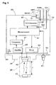
- the block diagram of Fig. 5 shows the electrical configuration of the thus-completed gas sensor 10.
- the electronic circuit board 70 includes a microprocessor 91 as a central component as well as circuit elements connected to the microprocessor 91, such as a digital-to-analog converter (D/A converter) 92, a driver 93, and a comparator 97 to which an amplifier 96 is connected.
- the thermistor 60 is directly connected to an analog input port PAP of the microprocessor 91.
- the driver 93 and the amplifier 96 are connected to the detecting-element assembly 40.
- the driver 93 is a circuit for driving the piezoelectric element 51 of the detecting-element assembly 40 for a predetermined time upon reception of an instruction from the microprocessor 91. Upon reception of an instruction from the microprocessor 91, the driver 93 outputs a plurality of rectangular waves. Upon reception of signals of rectangular waves output from the driver 93, the piezoelectric element 51 vibrates and functions as a transmitter, thereby transmitting ultrasonic waves into the measuring chamber 28.
- Ultrasonic waves transmitted into the measuring chamber 28 propagate rectilinearly while maintaining relatively high directivity and reflectively return from the reflective portion 33 at the bottom of the measuring chamber 28.
- the protective film 48 When the reflected ultrasonic waves reach the protective film 48, its vibrations are transmitted to the piezoelectric element 51 via the acoustic matching plate 50, and the piezoelectric element 51 now functions as a receiver and outputs electric signals corresponding to the vibrations. This is shown in Fig. 6. In Fig.
- period P1 is a period when the driver 93 outputs signals, and the piezoelectric element 51 functions as a transmitter, whereas period P2 is a period when vibrations induced by ultrasonic waves reflected from the reflective portion 33 are transmitted to the piezoelectric element 51, and the piezoelectric element 51 functions as a receiver.
- Signals output from the piezoelectric element 51 which functions as a receiver are input to the amplifier 96 and amplified.
- An output from the amplifier 96 is input to the comparator 97 and compared with a previously prepared threshold value Vref.
- the threshold value Vref is a level for discriminating a false signal which is output from the amplifier 96 under the influence of noise or the like.
- a false signal is also output under the influence of reverberations held in the detecting-element assembly 40 itself.
- the comparator 97 compares a signal received from the amplifier 96 with the threshold value Vref and inverts its output when the amplitude of vibration received by the piezoelectric element 51 exceeds a predetermined value. Monitoring an output from the comparator 97, the microprocessor 91 measures time ⁇ t between the timing of output of the first ultrasonic wave from the piezoelectric element 51 (timing t1 in Fig. 6) and the timing of inversion of output from the comparator 97 (timing t2 in Fig. 6), thereby obtaining time required for the ultrasonic wave to make a round trip over the distance L to the reflective portion 33 in the measuring chamber 28.
- Ultrasonic waves are known to propagate through a certain medium at speed C that is expressed below by Eq. (1).
- C RT ⁇ C pn X n ⁇ C vn X n ⁇ M n X n
- Eq. (1) is a general expression which holds with respect to a mixed gas of a plurality of components, and variable n is a suffix representing the n'th component. Therefore, C pn represents specific heat at constant pressure of the n'th component of a gas present in the measuring chamber 28; C vn represents specific heat at constant volume of the n'th component of a gas present in the measuring chamber 28; M n represents the molecular weight of the n'th component; and X n represents the ratio of concentration of the n'th component. Also, R is gas constant, and T is the temperature of a gas present in the measuring chamber 28.
- the propagation speed C depends on the temperature T and ratio-of-concentration X n of a gas present in the measuring chamber 28.
- the ratio-of-concentration X n i.e., gasoline concentration
- the concentration of gasoline vapor is determined; however, when concentration is known, the sensor can be used to obtain the temperature T or propagation distance L.
- the microprocessor 91 performs arithmetic operations at high speed according to the above-mentioned expressions and outputs a signal corresponding to the thus-obtained gasoline concentration to the D/A converter 92.
- This signal is output to an external device via the SGNL terminal of the connector 31.
- the SGNL terminal is connected to a computer (ECU) which controls fuel injection quantity of an internal combustion engine.
- the signal corresponding to gasoline concentration is read into the ECU and is used in the process of correcting fuel injection quantity in consideration of the quantity of gasoline purged from a canister.
- Fig. 5 does not show lines related to power supply, but the microprocessor 91 and other devices are each connected to a power line of supplying DC voltage Vcc and to the ground (ground line).
- the ground line is connected to the metal plate 36, which is insert-molded in the housing portion 22 of the flow path formation member 20, and to the casing 80.
- Fig. 5 schematically shows these members, but in actuality the metal plate 36 and the casing 80 (see Fig. 1) jointly form a box member (see Fig. 2) that covers the detecting-element assembly 40, and are maintained at the same electric potential to thereby establish an electromagnetic shield in terms of electricity. Therefore, the detecting-element assembly 40 and electronic circuit board 70 which are housed within the box member are effectively protected against external noise.
- the above-described gas sensor 10 of the present embodiment can accurately determine the concentration of gasoline vapor in a gas introduced into the measuring chamber 28 of the flow path formation member 20 by use of ultrasonic waves. Furthermore, the gas sensor 10 of the present embodiment is configured in the following manner: the detecting-element assembly 40 is attached to the measuring chamber 28 via the flange portion 41; the flange portion 41 is located opposite the measuring chamber 28 with respect to the piezoelectric element 51; and the casing body portion 43 in which the piezoelectric element 51 is housed protrudes from the flange portion 41 toward the measuring chamber 28. As a result, the following effects are yielded.
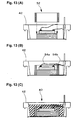
- FIGs. 8 and 9 are sectional views showing modified examples of a detecting-element assembly.
- a detecting-element assembly 40A according to the modified example of Fig. 8 assumes substantially the same configuration as that of the above-described embodiment.
- a flange portion 41A is not formed flatly at one end of the casing body portion 43, but is formed such that, as shown in Fig.
- an outer circumferential end portion is curved into a shape resembling the letter "L.”
- the linear distance to the piezoelectric element 51 housed in the casing body portion 43 is the same as that in the first embodiment; however, the length of a path to the piezoelectric element 51 becomes longer. Therefore, the piezoelectric element 51 is not susceptible, to a greater extent, to the influence of ultrasonic waves which leak from the piezoelectric element 51 into the interior of the element casing 42 and reflectively return from the joint between the flange portion 41A and the housing portion 22.
- a flange portion 41B may be joined to the casing body portion 43 via a support 49 provided at the center of the casing body portion 43. Also in this case, the path extending from the piezoelectric element 51 to the joint can be elongated.
- the terminals 55a and 55b may be provided in such a manner as to extend through the support 49.
- Fig. 10 is a process diagram showing a process for manufacturing a gas sensor.
- manufacture of the gas sensor 10 begins with assembly of a piezoelectric element (step S100).
- the protective film 48 is cut into a predetermined shape (circular shape in the present embodiment), and the acoustic matching plate 50 is bonded to the center of the protective film 48.
- the piezoelectric element 51 is concentrically bonded to the acoustic matching plate 50.
- a jig may be used for centering.
- Fig. 11(A) shows a state of bonding
- FIG. 11(B) shows a state after bonding.
- the lead wires 54a and 54b are connected to corresponding electrodes of the piezoelectric element 51 by means of, for example, soldering or discharge welding.
- the element casing 42 for housing the thus-obtained piezoelectric element assembly in a sealed condition is prepared (step S110).
- the element casing 42 is manufactured from a glass-filler-containing synthetic resin through injection molding. As a matter of course, cutting or a like process may be employed instead.
- the terminals 55a and 55b are insert-molded in the protrusions 56a and 56b formed on the inside of the element casing 42.
- step S120 the detecting-element assembly is assembled (step S120).
- the piezoelectric element assembly which was assembled in step S100 is attached to the element casing 42 which was manufactured in step S110.
- this work is performed in the following manner: a peripheral portion of the protective film 48 is bonded to the lower end face 45 of the element casing 42 by use of an adhesive, whereby the piezoelectric element assembly is fixed in place. Since the stepped portion 46 is formed on the end face 45 along the outer edge thereof, the protective film 48 can be readily bonded to the end face 45 in place. In this state, as shown in Fig.
- the tubular member 52 is inserted into the element casing 42 from its open end and fitted to the outer circumferential surface of the acoustic matching plate 50 (step S130).
- the polyethylene terephthalate film 52a and the copper foil 52c are bonded together via the bonding layer 52b, and the resultant laminate is rolled to obtain the tubular member 52 whose inside diameter matches the outside diameter of the acoustic matching plate 50.
- the tubular member 52 is not bonded to the acoustic matching plate 50, but is merely fitted thereto.
- step S140 the two lead wires 54a and 54b extending from the piezoelectric element 51 are connected to the terminals 55a and 55b, respectively, through soldering or a like process.
- step S140 all of required components are attached to the detecting-element assembly 40.
- urethane resin is filled into the element casing 42 from its open end (step S150).
- urethane resin which serves as filler is filled to such an extent as to cover the piezoelectric element 51 and the lead wires 54a and 54b extending from the upper end of the piezoelectric element 51 and as not to reach the upper end of the flange portion 41.
- Fig. 13(C) shows a state after filling.
- the flow path formation member 20 is manufactured. This manufacturing process is represented by step S200 and subsequent steps.
- a metal plate is press-worked to obtain the metal plate 36 to be subjected to insert molding (step S200).
- the metal plate 36 used in the present embodiment is unitarily formed from a substantially rectangular metal plate (a tinned steel plate in the present embodiment) through press-working.
- the flow path formation member 20 is formed through insert-molding such that the metal plate 36 is embedded therein (step S210).
- the flow path formation member 20 is molded from a glass-filler-containing synthetic resin.
- the metal plate 36 is held by use of a jig at a position where, after molding, the metal plate 36 is embedded in a bottom part of the housing portion 22.
- the terminals contained in the connector 31 are also embedded therein through insert molding.
- the previously manufactured detecting-element assembly 40 is welded to the housing portion 22 (step S230). Welding is performed ultrasonically. Prior to this ultrasonic welding, being mounted on a predetermined jig, the detecting-element assembly 40 is concentrically positioned in the recess 24. Since the inside diameter D1 of the recess 24 and the outside diameter D2 of the casing body portion 43 differ by about 2-3 millimeters (D1>D2), concentric alignment of the recess 24 and the detecting-element assembly 40 forms an average clearance of about 1 millimeter between the inner surface of the recess 24 and the outer surface of the casing body portion 43 of the detecting-element assembly 40.
- the detecting-element assembly 40 is vibrated at frequencies of an ultrasonic domain so as to strongly strike the lower surface of the flange portion 41 on a joint surface of the housing portion 22. Since the protrusion 59 is formed on the lower surface of the flange portion 41, force induced by ultrasonic vibrations concentrates on the protrusion 59. Concentration of mechanical energy on the protrusion 59 causes the protrusion 59 to be heated and then melted. As a result, the detecting-element assembly 40 is joined to the flow path formation member 20 such that the lower surface of the flange portion 41 is welded to the joint surface of the housing portion 22 while no clearance is left therebetween.
- Figs. 14(A) and 14(B) show a state before and after attachment of the detecting-element assembly 40. Notably, welding may be performed by another process, such as hot plate welding.
- the thermistor 60 is mounted in the mounting hole 25 formed in the flow path formation member 20 (step S240). Subsequently, a cushioning material 88 is placed on the detecting-element assembly 40 (step S250).
- the cushioning material 88 is a foamed member having an outside diameter substantially equal to that of the detecting-element assembly 40 and a thickness of several millimeters.
- the cushioning material 88 has holes formed therein so as to allow the terminals 55a and 55b protruding upward from the detecting-element assembly 40 to extend therethrough.
- the cushioning material 88 has such a thickness as to be able to intervene between the detecting-element assembly 40 and the electronic circuit board 70, which will be attached in the subsequent step.
- the cushioning material 88 is adapted to prevent urethane resin to be filled in a later step, which will be described later, from filling the periphery of the detecting-element assembly 40.
- the electronic circuit board 70 is housed from above in the housing portion 22 while the four members listed below are fitted into the corresponding connection holes formed in the board 70 (step S260).
- the casing 80 is attached to the housing portion 22 (step S270).
- the terminal 31d of the connector 31 is inserted through the connection hole 85 formed in the casing 80 and then soldered or brazed to the casing 80.
- a resin urethane resin in the present embodiment
- a resin is filled into the interior of the housing portion 22 (step S280) so as to embed the detecting-element assembly 40 and the electronic circuit board 70 in urethane resin through molding.
- Fig. 15 does not show the resin used in molding.
- a gas which contains gasoline vapor and whose gasoline vapor concentration has already been measured by use of another detecting apparatus is introduced into the measuring chamber 28.
- the gas sensor 10 is activated, and an output from the gas sensor 10 is calibrated (step S290).
- the gas sensor 10 is calibrated in the following manner: on the basis of the results of detection, a calibration curve showing the relationship between an output from the gas sensor 10 and gasoline concentration obtained through measurement by another measuring apparatus is obtained and written onto an EEPROM contained in the microprocessor 91.
- a trimmer or the like provided on the electronic circuit board 70 may be adjusted for calibration. In the latter case, preferably, an opening for allowing an adjustment tool to be inserted therethrough is formed in the casing 80, and adjustment is performed after the casing 80 is attached in place (before molding with resin is performed).
- the above-described method for manufacturing a gas sensor can easily manufacture a sensor configured such that the detecting-element assembly 40 is joined to a bottom part of the housing portion 22 by use of the flange portion 41 to thereby provide a sufficiently long path between the joint of the flange portion 41 and the piezoelectric element 51 housed in the detecting-element assembly 40. Also, since an average clearance of 1 millimeter or greater can be formed along the outer circumferential surface of the detecting-element assembly 40, a sensor unsusceptible to collection of foreign matter or the like can be easily manufactured. As a result, sufficient reliability and durability can be imparted to a sensor which is to be used in the market over a long term.
- Fig. 16 is a sectional view showing a schematic configuration of a sensor 100 according to the second embodiment.
- the second embodiment is similar to the first embodiment except that a detecting-element assembly 400 is formed integrally with a flow path formation member 200.
- the flow path formation member 200 is divided into two members, or an upper member and a lower member, at substantially the longitudinal center of a measuring chamber 28.
- the upper member having the housing portion 22 formed thereon is called an upper flow path member 200A
- the lower member having a reflective portion 30 formed therein is called a lower flow path member 200B.
- the shape of an assembly of the upper and lower flow path members 200A and 200B is similar to that of the first embodiment except that the detecting-element assembly 400 is formed integrally with the flow path formation member 200A.
- a container portion 420 of the detecting-element assembly 400 is formed from resin integrally with the housing portion 22 of the flow path formation member 200A. This container portion 420 assumes a shape corresponding to the shape of an assembly of the flange portion 41 and the casing body portion 43 of the first embodiment, and is open-ended.
- the protective film 48 on which the acoustic matching plate 50 and the piezoelectric element 51 are mounted is attached to the open end of the container portion 420 of the upper flow path member 200A such that a peripheral portion of the protective film 48 is bonded to the open end of the container portion 420 by use of an adhesive in a manner similar to that shown in Fig. 12.
- the attachment of the tubular member 52, the connection of the lead wires 54a and 54b, and the filling of urethane resin are performed.
- the disposition of the cushioning material 88, the attachment of the electronic circuit board 70, and the filling of a synthetic resin are performed.
- the thus-obtained sensor 100 exhibits functions and the like similar to those as exhibited by the first embodiment.
- the detecting-element assembly 400 which houses the piezoelectric element 51, and the housing portion 22 of the upper flow path member 200A are formed integrally with each other; i.e., no joint is involved. Therefore, the phenomenon that ultrasonic waves, which leak into the interior of the detecting-element assembly 400 from the piezoelectric element 51, reflectively return from a joint is not involved. Reflected waves which could return are from the joint between the upper flow path member 200A and the lower flow path member 200B. However, since the path extending from the joint is very long, the reflected waves are sufficiently damped, whereby the influence of the reflected waves in the form of, for example, reverberations is sufficiently reduced.
- a sufficient clearance is formed along the outer circumferential surface of the container portion of the detecting-element assembly 400.
- the second embodiment does not involve concentric alignment between the detecting-element assembly 400 and the recess. Therefore, manufacturing does not involve variations in clearance among products, and a problem of collection of foreign matter in the clearance is sufficiently suppressed. Furthermore, manufacturing does not involve ultrasonic welding, and sealing in relation to the measuring chamber 28 can be sufficiently established.
- the present invention has been described with reference to the embodiments, the present invention is not limited thereto. Without departing from the scope of the invention, as defined by the claims appended hereto, the present invention is applicable to, for example, temperature and specific heat sensors which utilize ultrasonic waves and to sensors which detect various properties of gas by use of techniques other than an ultrasonic technique.
Landscapes
- General Health & Medical Sciences (AREA)
- Health & Medical Sciences (AREA)
- Life Sciences & Earth Sciences (AREA)
- Chemical & Material Sciences (AREA)
- Analytical Chemistry (AREA)
- Biochemistry (AREA)
- Physics & Mathematics (AREA)
- General Physics & Mathematics (AREA)
- Immunology (AREA)
- Pathology (AREA)
- Investigating Or Analyzing Materials By The Use Of Ultrasonic Waves (AREA)
- Transducers For Ultrasonic Waves (AREA)
- Measuring Volume Flow (AREA)
Abstract
Description
wherein the element casing comprises a body portion for housing the element and a flange portion to be attached to the measuring chamber;
wherein the element casing comprises a tubular portion for housing the element, the tubular portion and the measuring chamber being integrally formed from resin;
- 10 ...
- gas sensor
- 20 ...
- flow path formation member
- 22 ...
- housing portion
- 24 ...
- recess
- 25 ...
- mounting hole
- 27 ...
- introduction path
- 28 ...
- measuring chamber
- 29 ...
- bypass
- 31 ...
- connector
- 32 ...
- inlet hole
- 33 ...
- reflective portion
- 34 ...
- outlet
- 35 ...
- discharge path
- 36 ...
- metal plate
- 40, 400 ...
- detecting-element assembly
- 41 ...
- flange portion
- 42 ...
- element casing
- 43 ...
- casing body portion
- 45 ...
- end face
- 46 ...
- stepped portion
- 48 ...
- film
- 49 ...
- support
- 50 ...
- acoustic matching plate
- 51 ...
- piezoelectric element
- 52 ...
- tubular member
- 52a ...
- polyethylene terephthalate film
- 52b ...
- bonding layer
- 52c ...
- copper foil
- 53 ...
- opening
- 54a, 54b ...
- lead wires
- 55a, 55b ...
- terminals
- 56a, 56b ...
- protrusions
- 59 ...
- protrusion
- 60 ...
- thermistor
- 70 ...
- electronic circuit board
- 72 ...
- connection hole
- 80 ...
- casing
- 83 ...
- cut-and-raised portion
- 85 ...
- connection hole
- 88 ...
- cushioning material
- 100 ...
- gas sensor
- 200A ...
- upper flow path member
- 200B ...
- lower flow path member
- 420 ...
- container portion
Also in this case, the path extending from the
- Cut-and-raised
portion 83 of themetal plate 36 which stands from a bottom part of thehousing portion 22; -
Terminals element assembly 40; - Terminals of the
thermistor 60; and - Three terminals of the
connector 31.
Claims (12)
- A sensor comprising: an element for transmitting and receiving ultrasonic waves and electric signals; an element casing housing the element; a measuring chamber, the element casing being attached to the measuring chamber; and an inlet for introducing an object to be measured by use of ultrasonic waves into the measuring chamber,
wherein the element casing comprises a body portion for housing the element and a flange portion to be attached to the measuring chamber;the element is attached to a first end of the body portion; andthe flange portion is integrated with a second end of the body portion located in opposition to the first end, to which the element housed in the body portion is attached. - A sensor as described in claim 1, wherein the body portion is molded from a synthetic resin.
- A sensor as described in claim 1 or 2, wherein the body portion is tubular, and the first end of the body portion is sealed with a sealing member;the element is bonded to the sealing member directly, or via a member aiding transmission of ultrasonic waves; andthe tubular body portion is filled with resin while housing the element.
- A sensor as described in any one of claims 1 to 3, wherein a portion of the measuring chamber to which the element casing is attached is one of inner walls which define the measuring chamber.
- A sensor as described in claim 4, wherein an inside diameter of the portion of the measuring chamber to which the element casing is attached is greater than an outside diameter of the body portion.
- A sensor as described in claim 5, wherein an inside diameter of the portion of the measuring chamber to which the element casing is attached is at least 2 mm greater than an outside diameter of the body portion.
- A sensor as described in any one of claims 1 to 6, wherein the object to be measured is gas; andthe sensor further comprises a detecting portion for detecting a condition of transmission of ultrasonic waves by means of an electric signal received from the element and determining a concentration of the gas from the detected condition.
- A sensor as described in claim 7, wherein the element casing is provided at a first end of the measuring chamber, and a reflective portion for reflecting ultrasonic waves is provided at a second end of the measuring chamber; andthe detecting portion is means for measuring time between transmission of an ultrasonic wave from the element casing and reception of the ultrasonic wave reflected from the reflective portion and determining the concentration of the gas from the measured time.
- A sensor as described in any one of claims 1 to 8, wherein an outside diameter of the flange portion is greater than that of the body portion.
- A sensor as described in any one of claims 1 to 8, wherein the flange portion comprises a member having an outside diameter smaller than that of the body portion and integrated with a central part of the second end of the body portion.
- A sensor comprising: an element for transmitting and receiving ultrasonic waves and electric signals; an element casing housing the element; a measuring chamber, the element casing being provided in the measuring chamber; and an inlet for introducing an object to be measured by use of ultrasonic waves into the measuring chamber,
wherein the element casing comprises a tubular portion for housing the element, the tubular portion and the measuring chamber being integrally formed from resin;the tubular portion is integrated with the measuring chamber at a position located a predetermined distance away from a region of the measuring chamber in which the object is present;the element is housed in the tubular portion of the element casing at an end of the tubular portion located on a side toward the measuring chamber; andthe end of the tubular portion located on the side toward the measuring chamber is sealed. - A method for manufacturing a sensor comprising: an element for transmitting and receiving ultrasonic waves and electric signals; an element casing housing the element; a measuring chamber; and an inlet for introducing an object to be measured by use of ultrasonic waves into the measuring chamber, the method comprising the steps of:forming the element casing from resin in such a manner that the element casing has a body portion for housing the element, and a flange portion integrated with the body portion;housing the element in the body portion at an end of the body portion and then substantially filling the interior of the body portion with resin; andfixing the element casing in such an orientation that the body portion is located within the measuring chamber and such that the flange portion comes into contact with a fixation portion of the measuring chamber from the outside of the measuring chamber.
Applications Claiming Priority (2)
| Application Number | Priority Date | Filing Date | Title |
|---|---|---|---|
| JP2002107459A JP3746728B2 (en) | 2002-04-10 | 2002-04-10 | Sensor and manufacturing method thereof |
| JP2002107459 | 2002-04-10 |
Publications (2)
| Publication Number | Publication Date |
|---|---|
| EP1353175A2 true EP1353175A2 (en) | 2003-10-15 |
| EP1353175A3 EP1353175A3 (en) | 2005-07-20 |
Family
ID=28449936
Family Applications (1)
| Application Number | Title | Priority Date | Filing Date |
|---|---|---|---|
| EP03007959A Withdrawn EP1353175A3 (en) | 2002-04-10 | 2003-04-09 | Piezoelectric sensor and method for manufacturing the same |
Country Status (3)
| Country | Link |
|---|---|
| US (1) | US7080543B2 (en) |
| EP (1) | EP1353175A3 (en) |
| JP (1) | JP3746728B2 (en) |
Families Citing this family (11)
| Publication number | Priority date | Publication date | Assignee | Title |
|---|---|---|---|---|
| JP2004228126A (en) * | 2003-01-20 | 2004-08-12 | Denso Corp | Electronic circuit housing |
| KR100645575B1 (en) * | 2004-06-15 | 2006-11-15 | 현대자동차주식회사 | Sensing device |
| US20060191318A1 (en) * | 2005-02-25 | 2006-08-31 | Mcbride Charles L | Digitally accessible sensor |
| US10651063B2 (en) * | 2005-06-18 | 2020-05-12 | Frederick A. Flitsch | Methods of prototyping and manufacturing with cleanspace fabricators |
| US7637163B2 (en) * | 2006-02-02 | 2009-12-29 | The Boeing Company | Thin-film ultrasonic probe |
| US8650958B2 (en) * | 2006-02-02 | 2014-02-18 | The Boeing Company | Thin-film ultrasonic probe having a flexible membrane |
| JP6212870B2 (en) * | 2013-01-28 | 2017-10-18 | セイコーエプソン株式会社 | Ultrasonic device, ultrasonic probe, electronic device and ultrasonic imaging apparatus |
| US10199028B2 (en) | 2013-05-21 | 2019-02-05 | Endress + Hauser Flowtec Ag | Ultrasonic transducer mounting assembly |
| JP6331396B2 (en) * | 2014-01-06 | 2018-05-30 | セイコーエプソン株式会社 | Ultrasonic device, ultrasonic probe, electronic apparatus, and manufacturing method of ultrasonic device |
| JP6897502B2 (en) * | 2017-11-02 | 2021-06-30 | 株式会社デンソー | Ultrasonic sensor |
| KR102466332B1 (en) * | 2018-01-02 | 2022-11-15 | 삼성전자주식회사 | Gas sensor package |
Family Cites Families (15)
| Publication number | Priority date | Publication date | Assignee | Title |
|---|---|---|---|---|
| US3890423A (en) * | 1973-07-27 | 1975-06-17 | Nusonics | Electroacoustic transducer assembly |
| US4773267A (en) * | 1980-03-31 | 1988-09-27 | Micro Pure Systems, Inc. | Ultrasonic sensing |
| US4365515A (en) * | 1980-09-15 | 1982-12-28 | Micro Pure Systems, Inc. | Ultrasonic sensing |
| US4900298A (en) | 1987-08-21 | 1990-02-13 | Cobe Laboratories, Inc. | Centrifuge drive and support assembly |
| JP3200168B2 (en) * | 1992-06-22 | 2001-08-20 | 株式会社日立製作所 | Attitude control mechanism |
| JPH0646392U (en) * | 1992-11-24 | 1994-06-24 | 株式会社カイジョー | Ultrasonic wave transceiver |
| US5392635A (en) * | 1993-12-30 | 1995-02-28 | At&T Corp. | Acoustic analysis of gas mixtures |
| EP0756696B1 (en) * | 1994-04-19 | 1998-01-14 | Siemens Aktiengesellschaft | Holder for ultrasonic transducers |
| JP3379073B2 (en) * | 1994-06-17 | 2003-02-17 | 本田技研工業株式会社 | Ultrasonic transducer |
| JPH0894590A (en) * | 1994-09-28 | 1996-04-12 | Honda Motor Co Ltd | Evaporative fuel concentration measuring device |
| US5627323A (en) * | 1995-05-25 | 1997-05-06 | Stern; Michael | Ultrasonic binary gas measuring device |
| JPH1164072A (en) * | 1997-08-20 | 1999-03-05 | Kaijo Corp | Interface level meter |
| JP2000121739A (en) * | 1998-10-16 | 2000-04-28 | Murata Mfg Co Ltd | Ultrasonic sensor and method of manufacturing the same |
| US6268683B1 (en) * | 1999-02-26 | 2001-07-31 | M&Fc Holding Company | Transducer configurations and related method |
| JP2002031621A (en) * | 2000-07-14 | 2002-01-31 | Ngk Spark Plug Co Ltd | Gas concentration sensor |
-
2002
- 2002-04-10 JP JP2002107459A patent/JP3746728B2/en not_active Expired - Fee Related
-
2003
- 2003-04-09 EP EP03007959A patent/EP1353175A3/en not_active Withdrawn
- 2003-04-09 US US10/409,587 patent/US7080543B2/en not_active Expired - Fee Related
Also Published As
| Publication number | Publication date |
|---|---|
| EP1353175A3 (en) | 2005-07-20 |
| JP3746728B2 (en) | 2006-02-15 |
| JP2003302383A (en) | 2003-10-24 |
| US7080543B2 (en) | 2006-07-25 |
| US20040003664A1 (en) | 2004-01-08 |
Similar Documents
| Publication | Publication Date | Title |
|---|---|---|
| US7080543B2 (en) | Sensor and method for manufacturing the same | |
| JP2783684B2 (en) | Filling condition measuring device | |
| US7513158B2 (en) | Ultrasonic sensor for use in automotive vehicle | |
| US7340959B2 (en) | Pressure sensor | |
| KR100642912B1 (en) | Flow Rate Measuring Apparatus | |
| CN114111928B (en) | High-frequency ultrasonic sensor suitable for gas flow detection | |
| US7082810B2 (en) | Gas sensor | |
| WO2016158334A1 (en) | Liquid surface position detection device | |
| US20110239780A1 (en) | Coupling element for an ultrasonic flow measuring device | |
| US6892565B2 (en) | Gas sensor and gas concentration detecting device | |
| US20040136271A1 (en) | Sonar transducer | |
| JP3861062B2 (en) | Gas sensor and gas concentration detection device | |
| JP2003302386A (en) | Sensor | |
| JP2003254951A (en) | Gas sensor and method of manufacturing the same | |
| JP3379073B2 (en) | Ultrasonic transducer | |
| JP2003302385A (en) | Sensor | |
| JP2003302387A (en) | Element container, sensor, and manufacturing method thereof | |
| CN114945808B (en) | Sensor device for detecting filling level and/or quality of fluid and method for manufacturing the same | |
| JP2004325402A (en) | Sensors and measuring devices | |
| JP2003329651A (en) | Gas sensor | |
| JP2003302384A (en) | Sensor | |
| US20080184794A1 (en) | Device for Measuring the Level of a Liquid in a Container With an Ultrasonic Transducer | |
| US20220333970A1 (en) | Ultrasonic Transducer and Method of Operating an Ultrasonic Transducer | |
| KR101304373B1 (en) | Device for measuring the level of a liquid in a container by means of an ultrasonic converter | |
| JP2003254950A (en) | Gas sensor |
Legal Events
| Date | Code | Title | Description |
|---|---|---|---|
| PUAI | Public reference made under article 153(3) epc to a published international application that has entered the european phase |
Free format text: ORIGINAL CODE: 0009012 |
|
| AK | Designated contracting states |
Kind code of ref document: A2 Designated state(s): AT BE BG CH CY CZ DE DK EE ES FI FR GB GR HU IE IT LI LU MC NL PT RO SE SI SK TR |
|
| AX | Request for extension of the european patent |
Extension state: AL LT LV MK |
|
| RIC1 | Information provided on ipc code assigned before grant |
Ipc: 7G 01N 29/02 B Ipc: 7G 01N 29/24 B Ipc: 7G 01N 29/22 A |
|
| PUAL | Search report despatched |
Free format text: ORIGINAL CODE: 0009013 |
|
| AK | Designated contracting states |
Kind code of ref document: A3 Designated state(s): AT BE BG CH CY CZ DE DK EE ES FI FR GB GR HU IE IT LI LU MC NL PT RO SE SI SK TR |
|
| AX | Request for extension of the european patent |
Extension state: AL LT LV MK |
|
| 17P | Request for examination filed |
Effective date: 20051028 |
|
| AKX | Designation fees paid |
Designated state(s): DE FR |
|
| 17Q | First examination report despatched |
Effective date: 20100827 |
|
| STAA | Information on the status of an ep patent application or granted ep patent |
Free format text: STATUS: THE APPLICATION IS DEEMED TO BE WITHDRAWN |
|
| 18D | Application deemed to be withdrawn |
Effective date: 20110107 |