EP1353156A2 - Reflectance Estimating Method - Google Patents
Reflectance Estimating Method Download PDFInfo
- Publication number
- EP1353156A2 EP1353156A2 EP03008355A EP03008355A EP1353156A2 EP 1353156 A2 EP1353156 A2 EP 1353156A2 EP 03008355 A EP03008355 A EP 03008355A EP 03008355 A EP03008355 A EP 03008355A EP 1353156 A2 EP1353156 A2 EP 1353156A2
- Authority
- EP
- European Patent Office
- Prior art keywords
- reflectance
- displacement
- principal component
- estimating
- displacement angle
- Prior art date
- Legal status (The legal status is an assumption and is not a legal conclusion. Google has not performed a legal analysis and makes no representation as to the accuracy of the status listed.)
- Granted
Links
Images






Classifications
-
- G—PHYSICS
- G01—MEASURING; TESTING
- G01J—MEASUREMENT OF INTENSITY, VELOCITY, SPECTRAL CONTENT, POLARISATION, PHASE OR PULSE CHARACTERISTICS OF INFRARED, VISIBLE OR ULTRAVIOLET LIGHT; COLORIMETRY; RADIATION PYROMETRY
- G01J3/00—Spectrometry; Spectrophotometry; Monochromators; Measuring colours
- G01J3/46—Measurement of colour; Colour measuring devices, e.g. colorimeters
-
- G—PHYSICS
- G01—MEASURING; TESTING
- G01J—MEASUREMENT OF INTENSITY, VELOCITY, SPECTRAL CONTENT, POLARISATION, PHASE OR PULSE CHARACTERISTICS OF INFRARED, VISIBLE OR ULTRAVIOLET LIGHT; COLORIMETRY; RADIATION PYROMETRY
- G01J3/00—Spectrometry; Spectrophotometry; Monochromators; Measuring colours
- G01J3/46—Measurement of colour; Colour measuring devices, e.g. colorimeters
- G01J3/50—Measurement of colour; Colour measuring devices, e.g. colorimeters using electric radiation detectors
- G01J3/504—Goniometric colour measurements, for example measurements of metallic or flake based paints
-
- G—PHYSICS
- G01—MEASURING; TESTING
- G01N—INVESTIGATING OR ANALYSING MATERIALS BY DETERMINING THEIR CHEMICAL OR PHYSICAL PROPERTIES
- G01N21/00—Investigating or analysing materials by the use of optical means, i.e. using sub-millimetre waves, infrared, visible or ultraviolet light
- G01N21/17—Systems in which incident light is modified in accordance with the properties of the material investigated
- G01N21/47—Scattering, i.e. diffuse reflection
- G01N21/4738—Diffuse reflection, e.g. also for testing fluids, fibrous materials
Definitions
- the present invention relates to a reflectance estimating method, and more particularly to a reflectance estimating method for estimating a reflectance of an object at an arbitrary displacement angle which displacement angle is an angle representing displacement from the direction of a regular reflection of light from the object.
- a light incident angle to the object is often selected at 45°, but a light receiving angle (displacement angle) for measuring the reflectance is not generally defined. It is different depending on the measuring apparatus used or on the measuring method. In this manner, there has not been considered the properness of the light receiving angle (displacement angle) for measuring the reflectance, which is to be used for estimating the reflectance at an arbitrary displacement angle.
- an object of the present invention is to provide a method for estimating the reflectance which is usable for faithful presentation of a color of an object.
- the present invention is featured by following (1) to (14):
- the reflectance estimating method of the invention estimates a reflectance at an arbitrary displacement angle.
- a principal component analysis is executed on reflectances at predetermined plural displacement angles within a predetermined angular range, for example from about 10° to about 90°.
- a principal component vector, obtained as a result of the principal component analysis and representing the feature of the reflectance for the displacement angle, is taken as an eigenvector, also a principal component is taken as an eigenvalue, and characteristics of the eigenvector are determined on the relationship between the eigenvalue and the displacement angle.
- a representative displacement angle is determined from the obtained characteristics, then a basic equation on the reflectance, represented by the eigenvalue, the eigenvector and a coefficient to be multiplied on the eigenvector, is determined in advance, and the coefficient is determined based on such basic equation, the representative displacement angle and the reflectance at the representative displacement angle.
- the basic equation utilizing the determined coefficient and the eigenvector is defined as a calculation equation, and a reflectance at a displacement angle other than the predetermined displacement angles is estimated in the predetermined angular range, utilizing such calculation equation.
- the reflectance is estimated by extrapolating the eigenvector.
- the invention is applied to the estimation of a reflectance which is advantageously employable, for example in an image output of an automobile, in designing an object having a color such as an external paint color (external panel color) of the automobile.
- CG computer graphics
- reflectance is considered as a physical amount for reproducing the object color, and spectral reflectance of the surface of the object is employed. Since the spectral reflectance may be given in different values depending on a light receiving direction of a measuring instrument, in a sample of a complex shape such as fibers or a metallic painted surface, the present embodiment employs, as the spectral reflectance, a spectral steric angle reflectance (hereinafter simply called reflectance) obtained by displacing a light incident angle to the object and a light receiving angle of a light receiving element which receives the light reflected by the object.
- reflectance a spectral steric angle reflectance
- the present invention is not limited to the spectral steric angle reflectance but may simply employ a reflectance.
- a reflectance estimating apparatus for CG of the present embodiment is provided with a personal computer 16.
- the personal computer 16 includes a keyboard 10 for entering color data or the like, a computer main body 12 for processing related data in order to estimate the desired reflectance according to a program stored in advance, and a CRT 14 for displaying the reflectance or the like obtained by processing in the computer main body 12.
- the computer main body 12 includes a CPU, a ROM and a RAM, and also has a memory for storing data such as a reflectance to be explained later.
- the reflectance of an object varies depending on an arbitrary displacement angle, but the present inventor has obtained a knowledge that a principal component analysis on reflectances at predetermined plural displacement angles provides a feature on the reflectance, and the reflectances at plural displacement angles can be estimated from such feature amount.
- a principal component vector obtained by the principal component analysis represents the feature of the reflectance at a displacement angle
- the present embodiment utilizes an eigenvector which is the principal component vector obtained as a result of the principal component analysis, thereby estimating a reflectance at a displacement angle other than the predetermined displacement angles.
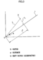
- a vector X can be reconstructed by a vector ⁇ obtained in the principal component analysis, an eigenvector b, and a coefficient k.
- data to be analyzed are represented by a real vector X of an order p.
- the provisional vector X' is assumed as the real vector X, as indicated in the equation (3).
- the distance l 1 can be minimized by maximizing the distance a.
- An expected value E[a] and a dispersion E[a 2 ] of the distance a can be represented by following equations (9) and (10) :
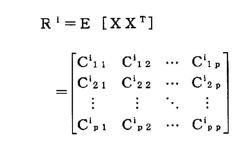
- R is a co-dispersion matrix of the vector X and is a real object matrix.
- the unit vector b which has an extreme value of the dispersion ⁇ (b) in the equation (11) is an eigenvector of the co-dispersion matrix R. Such eigenvector will be explained in the following.
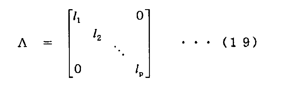
- a constant l satisfying the equation (14) is an eigenvalue
- the unit vector b is an eigenvector corresponding to the eigenvalue.
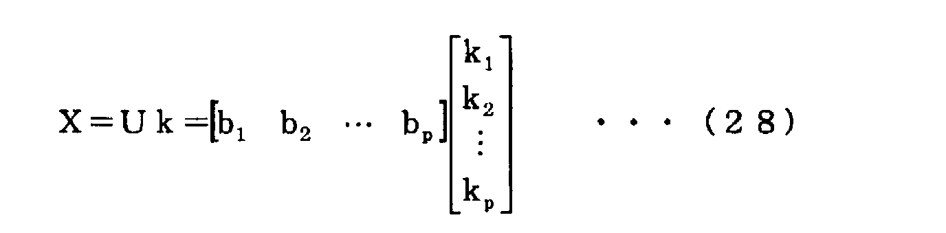
- the vector X can be reconstructed with the eigenvector ⁇ b 1 , b 2 ,..., b p ⁇ .
- the vector X can be reconstructed by the vector ⁇ , the eigenvector ⁇ b 1 , b 2 ,..., b p ⁇ and the coefficient ⁇ k 1 , k 2 ,..., k p ⁇ .
- the eigenvector ⁇ b 1 , b 2 ,..., b p ⁇ of a multiple order is employed but the amount of data increases in such method.
- a method of reducing the number of order without decreasing the information amount there will be explained a method of reducing the number of order without decreasing the information amount.
- a lower number of order can be realized without a significant decrease in the information amount, by leaving, among the p orthogonal axes of the eigenvector ⁇ b 1 , b 2 ,..., b p ⁇ , axes showing large dispersions and deleting axes showing small dispersions.
- Equation (32) representing the vector X can be written as a following equation (34):
- m axes (m ⁇ p) are selected in the descending order of the engenvalue, and a new vector *X constituted by the selected m eigenvalues is represented by a following formula (35) :
- the error e is orthogonal to the vector *X, and this fact is called a principle of orthogonality.
- a lower number of order can be realized without significantly losing the information amount, by leaving the axes of larger dispersions among the p orthogonal axes of the eigenvector b and deleting the axes of smaller dispersions.
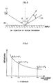
- a light source 22 has an incident angle ⁇ , and a direction 24 of a reflective angle which is the same as the incident angle ⁇ is called a normal reflecting direction.
- An angle representing displacement from the normal reflecting direction 24 toward a normal line is represented by a displacement angle ⁇ .
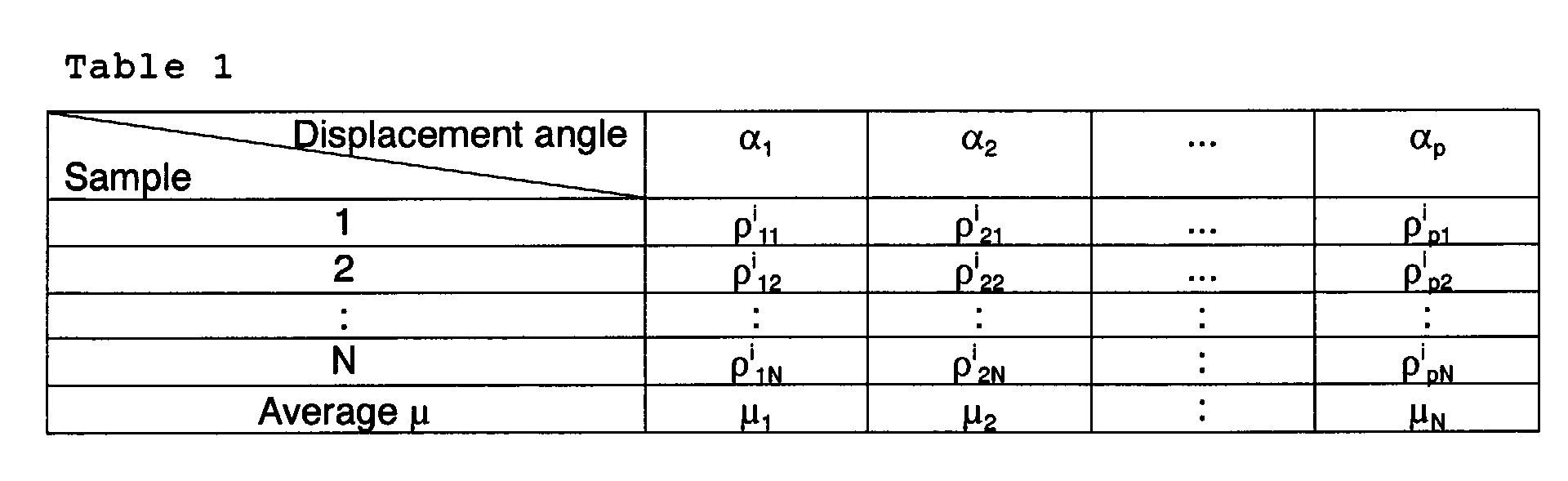
- Fig. 5 is a characteristic chart showing a relationship between the displacement angle ⁇ and the reflectance. As the reflectance varies by a wavelength ⁇ , a reflectance at an arbitrary wavelength ⁇ and at a displacement angle ⁇ 1 , ⁇ 2 ,..., ⁇ p ⁇ is represented by ⁇ 1 , ⁇ 2 ,..., ⁇ p ⁇ .
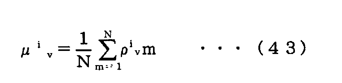
- a reflectance at an arbitrary wavelength ⁇ i and at a displacement angle ⁇ 1 , ⁇ 2 ,..., ⁇ p ⁇ is represented by a vector X of a following equation (38) :
- X i ⁇ i 1 , ⁇ i 2 ,..., ⁇ i p ⁇ T
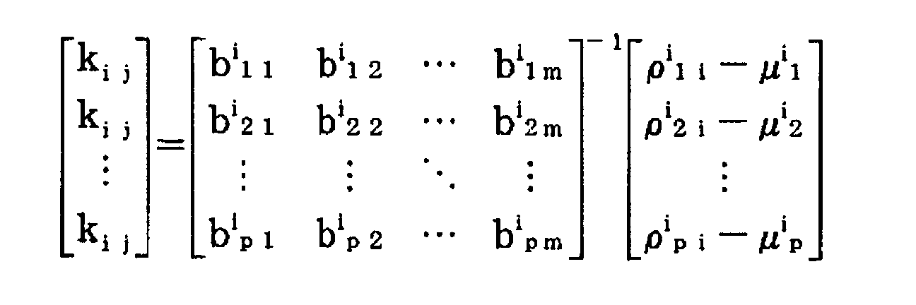
- the reflectance ⁇ at an arbitrary displacement angle ⁇ can be represented by the average vector ⁇ , the eigenvector b and the coefficient k. Consequently, by determining the coefficient k from a known reflectance measured on the object, the reflectance at a displacement angle other than the reflectances at the known displacement angles can be derived from this equation. This equation is solved for the coefficient k to obtain:
- the determination of the reflectance is executed for all the wavelengths utilizing the wavelength ⁇ i .
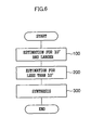
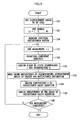
- a processing routine shown in Fig. 6 is executed and the sequence proceeds to a step 100.
- a step 100 estimates the reflectance (for example spectral steric angle reflectance) for displacement angles of 10° or larger.
- a next step 200 estimates the reflectance for displacement angles less than 10°.
- a step 300 synthesizes the reflectances obtained in the steps 100 and 200, thereby deriving the reflectances for all the displacement angles, whereupon the present routine is terminated.
- the reflectance estimation is separated at a boundary of a displacement angle of 10° in order to improve the precision of the result of estimation, since the estimation of the reflectance at the normal reflecting direction 24 by the principal component analysis may provide unstable results for example because of a fluctuation in the light measurement data.
- the present inventor has obtained an experimental result that a displacement angle of about 10° is a most preferred as an angle for obtaining the normal reflection data in the vicinity of the normal reflecting direction 24, i.e., at a displacement angle of 0°. This is because the principal component analysis of the aforementioned principle provides an unstable result of analysis if the boundary of the displacement angle is taken smaller than about 10°.
- a boundary for the displacement angle is set at 10°, and different processes are executed for estimating the reflectance for a displacement angle less than 10° (estimation in the vicinity of the normal reflection), and for a displacement angle of 10° or larger (estimation for principal displacement angle), More specifically, the reflectance for a displacement angle of 10° or larger is estimated by the principal component analysis of the multi-variable analysis explained in the foregoing, and the reflectance for a displacement angle less than 10° is estimated by another estimation process. Examples of the estimation process for the displacement angle less than 10° include an insertion of measured data, a multiple regression analysis of multi-variable analysis and an interpolation process.
- the reflectance of each sample may be measured with a reflectance measuring device (for example a spectral reflectance factor measuring device), or may be obtained by reading data of measured values, or entered from a keyboard.
- a next step 106 sets an arbitrary wavelength ⁇ i for fixing the wavelength ⁇ i as explained in the foregoing principle of reflectance estimation. In this manner there can be obtained reflectance or light measurement data for a displacement angle at the arbitrary wavelength ⁇ i .
- a next step 108 initiates a principal component analysis according to the foregoing principle, utilizing the light measurement data set in the step 106, and a step 110 derives an engenvalue 1 and an eigenvector b obtained by the principal component analysis.
- the step 110 also derives an average vector ⁇ .
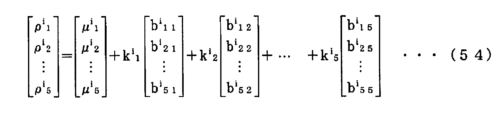
- a next step 112 reads a known reflectance of the object of which reflectance is to be estimated. Number of the reflectance to be read in this step corresponds to the aforementioned variable m. Based on thus read known reflectances, a step 114 derives a coefficient k utilizing the coefficient-deriving equation explained in the foregoing. Thus, a basic equation for the reflectance, shown in (50), is determined. A next step 116 utilizes the basic equation determined in the step 114 to derive a reflectance at an arbitrary displacement angle. The reflectance derived in this step includes a reflectance of a displacement angle other than the displacement angles read in the step 112.
- a step 118 discriminates whether the above-described process for the wavelength set in the step 106 has been completed for all the wavelengths, for example all the visible wavelength range (such as 400 to 700 nm), and, if not completed, the above-described process is executed in repetition, but, if completed, the present routine is terminated.
- the wavelength set in the step 106 is preferably set at wavelength values sufficient for color reproduction within the wavelength range to be utilized as the reflectance data, for example at every 10 nm.
- the estimation of the reflectance for a displacement angle less than 10° in the step 200 is executed, for example, by an insertion of actually measured data.
- the reflectances employing the measured data involve a certain error but can provide a more or less smooth curve.
- the present embodiment allows to easily determine the reflectance of a displacement angle other than the reflectances of the displacement angles which are already known as measured data, by the basic equation for the reflectance derived from the eigenvector obtained from the principal component analysis, so that a desired reflectance can be obtained while reducing the amount of the measured data.
- the reflectance estimation for a displacement angle less than 10° in the step 200 reliability of the result is low even if measured values are faithfully reproduced since the result of measurement of the reflectance for a displacement angle less than 10° shows fluctuation with a large error.
- the reflectance data are indispensable also for the displacement angles less than 10°.
- emphasis may be given to a smooth continuity of the image display rather than to the reliability of the reflectance to be utilized.
- an abrupt variation in the reflectance if present when the displacement angle is changed continuous manner, may cause a flickering or a color jump in the image display at a displacement angle corresponding to such abrupt variation in the reflectance, thereby giving an uncomfortable feeling to the user.
- the reflectance is processed for each wavelength ⁇ i .
- the present embodiment processes the reflectance not for each wavelength ⁇ I but by grasping an entire feature for example over a wavelength range of the visible light.
- luminocity or brightness is employed for grasping the entire feature over the wavelength range.
- the present embodiment has a configuration approximately similar to that of the foregoing embodiment, wherein parts same as in the foregoing embodiment are represented by same symbols and omitted from the detailed description.
- the present embodiment employs an incident angle of 60°, instead of 45° which is usually utilized as the incident angle ⁇ . This is to enable the use of an angle 90° as a representative displacement angle to be determined from first to fifth principal component vectors, as will be explained in the following.
- the present inventor has obtained a knowledge that a featuring displacement angle exists, by employing the luminocity for grasping the entire feature over the wavelength range.
- the luminocity for grasping the entire feature over the wavelength range.
- a color of an object can be determined from a spectral distribution (spectral radiation luminance) of an incident light to a human eye when looking at such object.
- the spectral radiation luminance I( ⁇ ) can be determined from the light of a main light source, such as a solar light.
- a luminocity or brightness can be represented by considering visibility characteristics, called standard relative luminous efficiency y( ⁇ ), in combination with the spectral radiation luminocity I( ⁇ ).
- the luminocity Y defined in the equations (51), (52) is used for the aforementioned principal component analysis to obtain a principal component vector (eigenvector) and an eigenvalue.
- a feature found for each principal component vector in this analysis is understood to represent the entire feature over the wavelength range for each principal component vector.
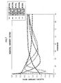
- Fig. 7 shows first to fifth principal component vectors obtained as a result of the principal component analysis.
- Each of the principal component vectors (eigenvectors), from the first one to the fifth one obtained by the principal component analysis, as respectively shown in Figs. 8A to 8E, has a feature point in the characteristics as a function of the displacement angle, different for each vector.
- the principal component vectors from the first one to the fifth one are considered, but it may also be applied to a sixth principal component vector or that of a higher order.
- the feature point means a displacement angle where the characteristics as a function of the displacement angle assumes a maximum value or a minimum value in each principal component vector (eigenvector).
- the first principal component vector has monotonously decreasing characteristics in which the value gradually decreases as shown in Fig. 8A, and the feature point can be considered to exist at both ends, namely at 10° and 90°.
- the second principal component vector has monotonously increasing characteristics in which the value gradually increases as shown in Fig. 8B, and the feature point can be considered, as in the first principal component vector, to exist at both ends, namely at 10° and 90°.
- the third principal component vector is of characteristics having a single maximum value in which the value gradually increases to such maximum value and then gradually decreases thereafter as shown in Fig. 8C, and the feature point can be considered to exist at 26° corresponding to the maximum value.
- the fourth principal component vector is of characteristics having a single maximum value and a single minimum value in which the value gradually increases to such maximum value, then gradually decreases to such minimum value and gradually increases thereafter as shown in Fig. 8D, and the feature point can be considered to exist at 16° corresponding to the maximum value and at 38° corresponding to the minimum value.
- the fifth principal component vector is of characteristics having a single maximum value and a single minimum value, as in the fourth principal component vector, in which the value gradually increases to such maximum value, then gradually decreases to such minimum value and gradually increases thereafter as shown in Fig. 8E, and the feature point can be considered to exist at 23° corresponding to the maximum value and at 46° corresponding to the minimum value.
- a feature point means a point where the graph assumes a greatest or least value or constitutes a maximum or minimum point.
- the principal component vectors can be considered with a contribution factor of about 99 % or higher by adopting the first and second principal component vectors, 99.9 % or higher by adopting the first to third principal component vectors, 99.97 % or higher by including the fourth principal component vector, and 99.99 % or higher by including the fifth principal component vector.
- the present inventor has obtained a knowledge that the adoption up to the fifth principal component vector is sufficient for extracting the features. More specifically, the feature extraction can be achieved by considering down to the second principal component vector, preferably to the third principal component vector, more preferably to the fourth principal component vector and most preferably to the fifth principal component vector.
- the present inventor has obtained a knowledge that the adoption down to the fourth is sufficient for enabling the reflectance estimation with a smaller amount of data, and has thus reached following feature points. More specifically, the representative displacement angles are the feature points of the first to fourth principal component vectors and are following five displacement angles: 10°, 90°, 26°, 38° and 16°.
- the displacement angles enabling to grasp the feature of the entire wavelength range are 10°, 16°, 26°, 38° and 90°. These five displacement angles are adopted in the following description.
- the present inventor has also obtained an experimental result indicating that these five displacement angles ⁇ 10°, 16°, 26°, 38° and 90° ⁇ are most effective and the precision is deteriorated even with a slight aberration for example by 1°.
- these displacement angles are anticipated to vary by an error in the measuring apparatus which defines the angle. Therefore, the values of these five displacement angles ⁇ 10°, 16°, 26°, 38° and 90° ⁇ are not limited to such figures within an allowance of a measurement error. Also these values are still effective in a vicinity of these five displacement angles ⁇ 10°, 16°, 26°, 38° and 90° ⁇ though the accuracy is deteriorated, and may therefore be effective for other displacement angles in the vicinity.
- these five displacement angles have different priorities according to the contribution factors thereof. More specifically, for grasping the feature of the entire wavelength range, the priority is highest in the displacement angles of 10° and 90°, then in the displacement angle of 26°, and then the displacement angles of 16° and 38°. Therefore, a preferred utilization of the displacement angles is achieved by utilizing two or more displacement angles among five. For example, in case of using two displacement angles, it is preferred to use two displacement angles of 10° and 90°, and, in case of using three displacement angles, it is preferred to use three displacement angles of 10°, 90° and 26°. In case of using four displacement angles, it is preferred to use four displacement angles of 10°, 90°, 26° and 16°, or 10°, 90°, 26° and 38°.
- the equations (50), (55) become tensor-containing equations if the wavelength ⁇ i is taken into consideration.
- a step 120 executes a process routine shown in Fig. 10, as a displacement angle setting process explained in the foregoing principle.
- a next step 144 initiates a principal component analysis utilizing the luminocity Y shown in the equations (51), (52) as explained in the principle of the reflectance estimation, and a step 146 derives an engenvalue 1 and an eigenvector b obtained by the principal component analysis. The step 146 also derives an average vector ⁇ .
- a next step 148 derives, in the result of the principal component analysis, a feature point representing the feature of each principal component vector.
- the feature point is a maximum or minimum value in the characteristics of each principal component vector, and is determined a predetermined principal component vector (fourth principal component vector in the present embodiment). There is also determined a cumulative contribution factor.
- a next step 150 determines a range of the eigenvectors to be utilized. This is a process for determining the principal component vectors providing a cumulative contribution factor of a predetermined value or higher, and, in the present embodiment, derivation is executed down to the fourth principal component vector providing a cumulative contribution factor of 99.98 %.
- a next step 152 derives feature points down to the fourth principal component vector, namely displacement angles to be utilized (in the present embodiment, five displacement angles of 10°, 90°, 26°, 38° and 16°).
- the reflectance may be measured with a reflectance measuring device (for example a spectral reflectance factor measuring device), or may be obtained by reading data of measured values, or entered from a keyboard.
- a next step 126 sets an arbitrary wavelength ⁇ i (procedure 1), and a step 128 initiates a principal component analysis in a similar manner as explained in the foregoing, and a step 130 derives an engenvalue 1, an eigenvector b and an average vector ⁇ obtained by the principal component analysis. As explained in the foregoing, the step 130 extracts the eigenvalues and the eigenvectors of the first to fifth principal component vectors for calculating the coefficient k (procedure 2).
- a next step 132 reads the reflectance of an object which is to be subjected to estimation.
- the reflectance is measured for five displacement angles set in the foregoing.
- a step 134 derives the coefficient k, utilizing the aforementioned equation (55) for deriving the coefficient (procedure 3). In this manner there is determined the basic equation for the reflectance, shown in (50).
- a next step 138 discriminates whether the above-described process for the wavelength set in the step 106 has been completed for all the wavelengths, for example all the visible wavelength range (such as 400 to 700 nm), and, if not completed (procedure 5), the above-described process is executed in repetition, but, if completed, the present routine is terminated.
- all the visible wavelength range such as 400 to 700 nm
- the reflectance estimation in the step 200 for an displacement angle less than 10° is executed as in the foregoing embodiment.
- the present embodiment is capable, by introducing a concept of luminocity instead of the reflectance, of grasping the feature of the entire wavelength range for example of the visible light, and finding a displacement angle constituting a feature point. It is thus rendered possible to determine the reflectance at an arbitrary displacement angle, based only on data limited to the measured data of the displacement angles constituting the feature points in the reflectance.
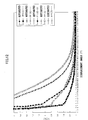
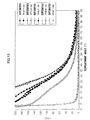
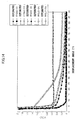
- Figs. 11, 12, 13 and 14 show characteristics of reflectance, on different samples, for the displacement angle from 0° to 90° including the estimation by the principal component analysis in the present embodiment and those of the measured values of respective samples. As shown in these charts, there was obtained a result of estimation close to the measured data. It is also understood that the result of estimation has an interpolating function for the measured data. More specifically, the measured data may show a fluctuation, namely a slight variation of the characteristic curve for example by the measuring conditions, but the estimation provides a characteristic reflectance curve showing a continuity with an interpolating effect. This will be ascribable to a fact that the principal component analysis, against a variation in the displacement angle, estimates a reflectance in which the feature of such displacement angle is reflected.
- a reflectance estimation for a displacement angle less than 10° has a low reliability because of a larger error, but is still needed for an image display such as CG. In case of an image display with a continuous change in the displacement angle, it is effective to given emphasis on the smooth continuity of the image display.
- the extrapolation of the reflectance itself results in a number of steps, since it has to be executed for each objected surface (painted surface) and for each wavelength.
- the extrapolation for example of the first to fifth principal component vectors has to be executed similarly for each wavelength, but can be easily achieved for each painted surface if the reflectances for the five displacement angles are obtained.
- the foregoing embodiments executes an estimation of the reflectance principally for a displacement angle of 10° or larger.
- the present embodiment is to estimate the reflectance at a displacement angle less than 10°, namely in a vicinity of the normal reflecting direction, where the measured data tend to become unstable.
- the present embodiment has a configuration approximately similar to that of the foregoing embodiments, wherein parts same as in the foregoing embodiments are represented by same symbols and omitted from the detailed description.
- the reflectance at a displacement angle less than 10°, larger in the error component, is excluded in the principal component analysis. However, in the CG, the reflectance at a displacement angle less than 10° is also required for ensuring continuity of the image.
- the reflectance at a displacement angle less than 10° can be estimated for example by the use of actually measured data or by an interpolation process as explained in the foregoing, but data of a sufficient amount are necessary.
- the present inventor has made various experiments and has obtained a knowledge that a time-sequential estimation is effective for the estimation with limited data.
- the present embodiment employs the time-sequential estimation for estimating the reflectance of a displacement angle less than 10°. More specifically, the reflectance estimation by the time-sequential estimation is executed by considering a change in the reflectance resulting from an increase or a decrease of the displacement angle as a time-sequential change.
- An example of the method effective for such time-sequential estimation is ARIMA (auto regressive integrated moving average) model.
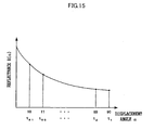
- Such reflectances R( ⁇ ) at the times t are used to estimate a reflectance at a displacement angle less than 10°.
- the estimation is executed in succession in a decreasing direction of the displacement angle ⁇ from 10° for which the estimation is made by the principal component analysis, the reflectance changes smoothly in the vicinity of 10° where the method of estimation is switched. Therefore, in case of an image display such as in CG, there can be assured a continuity of the image.
- the time-sequential estimation for example based on actually measured data of the reflectance usually provides a satisfactory result to about 5°, but the reflectance often shows an abrupt increase at a displacement angle in a vicinity of the normal reflecting direction.
- Fig. 16 shows a case where the reflectance is estimated by a curve approximation (indicated by a curve 34) in a displacement angle range of 0° to 5°, by a time-sequential estimation (indicated by a curve 32) in a displacement angle range of 5° to 10°, and by a principal component analysis (indicated by a curve 30) in a displacement angle range of 10° and larger.
- a curve approximation indicated by a curve 34
- time-sequential estimation indicated by a curve 32
- a principal component analysis indicated by a curve 30
- the present embodiment provides another method of estimating the reflectance at a displacement angle less than 10°, namely in the vicinity of the normal reflecting direction, by the principal component analysis only.
- the present embodiment has a configuration approximately similar to that of the foregoing embodiments, wherein parts same as in the foregoing embodiments are represented by same symbols and omitted from the detailed description.
- the reflectance at a displacement angle less than 10°, larger in the error component is excluded in the principal component analysis, but, in the present embodiment, the reflectance at a displacement angle less than 10° is also considered to determine the complete principal component vector including a range where the displacement angle ⁇ is 0° to 9°, and the reflectance is estimated over a displacement angle range of 0° to 90°, from the foregoing equation (50).
- the measured data in the displacement angle range of 0° to 9° are used to determine an eigenvalue, an eigenvector (principal component vector), an average vector and a coefficient k, thereby setting the basic equation.
- the present embodiment provides another method of estimating the reflectance at a displacement angle less than 10°, namely in the vicinity of the normal reflecting direction, by a multiple regression analysis.
- the present embodiment has a configuration approximately similar to that of the foregoing embodiments, wherein parts same as in the foregoing embodiments are represented by same symbols and omitted from the detailed description.
- the present embodiment estimates the reflectance at a displacement angle ⁇ less than 10°, utilizing the measured data of the reflectance in the principal component analysis employed for the displacement angle of 10° or larger as explained in the foregoing and executing a multiple regression analysis.
- a suffix i indicates a displacement angle less than 10°, namely 0, 1,..., 9.
- displacement angles ⁇ 1 , ⁇ 2 , ⁇ 3 ,... indicate arbitrary displacement angles at 10° or larger in the aforementioned principal component analysis.
- a i , b i , c i , d i ,... indicate coefficients for the respective displacement angles.
- the present inventor have made estimation of the reflectance by employing all the displacement angles as the arbitrary displacement angles of 10° or larger in the principal component analysis, to be employed in the multiple regression analysis according to the above equation, but has obtained a result that it is preferable, as such displacement angles, to employ the actually measured reflectances at the displacement angles constituting the feature points of the principal component vectors. More specifically, there is obtained a knowledge that there are preferred the displacement angles ⁇ of the principal component vectors having a large cumulative contribution factor, and that five displacement angles ⁇ 10°, 90°, 26°, 38°, 16° ⁇ constituting the feature points of the first to fourth principal component vectors should be considered.
- the five displacement angles ⁇ 10°, 90°, 26°, 38°, 16° ⁇ are employed with the reflectance y i at the displacement angle constituting the feature point as an explanatory variable to determine the reflectance y i at a displacement angle ⁇ less than 10° as a result of analysis. In this manner it is rendered possible to easily estimate the reflectance y i at a displacement angle ⁇ less than 10°.
- the reflectance for a displacement angle less than 10° is estimated by the multiple regression analysis, but there may also be executed, instead of the estimation by the multiple regression analysis, an estimation with a neural network or a sequential information interpolating process for intermediate color estimation (for example cf. Japanese Patent No. 3109336 "color reproducing method").
- the estimation process by a neutral network is constructed by setting an explanatory variable as an input, also setting a desired variable as an output and executing a study process utilizing the reflectances at the aforementioned displacement angles constituting the feature points and the reflectance for the displacement angle less than 10° as teacher data.
- the reflectance estimation in the foregoing embodiments functions effectively also for a solid surface, a metallic surface, a pearl mica surface or another arbitrary painted surface constituting major categories of the painting. It is particularly preferable to classify the surfaces into solid, metallic, pearl mica and others and to execute the reflectance estimating method of the present invention for each classified category. In this manner the precision can be further improved.
- the present invention is not limited to such angular range.
- the reflectance estimation may be executed for a displacement angle exceeding about 90° or for a displacement angle less than about 0°.
- the present invention executes, based on an eigenvector which is a principal component vector indicating the feature of the reflectance obtain by the principal component analysis on the reflectances at predetermined plural displacement angles, a reflectance estimation at a displacement angle other than the predetermined displacement angles, thereby providing an effect that the feature of the reflectance at a displacement angle is reflected also in another displacement angle and the reflectance can be estimated at an arbitrary displacement angle in which such feature of the reflectance is reflected.
- a sample for obtaining light measurement data is set to obtain reflectances.
- a principal component analysis is executed to obtain an eigenvalue l and an eigenvector b.
- a basic equation for reflectance is determined by deriving a coefficient k, utilizing a known reflectance of an object of which reflectance is to be estimated.
- a process of deriving a reflectance at an arbitrary displacement angle is executed for all the wavelengths, for example over a visible wavelength range. In this manner, the reflectance of an object at an arbitrary displacement angle can easily be obtained by utilizing the basic equation for the reflectance derived from the eigenvector obtained from the principal component analysis of the measured data.
Landscapes
- Physics & Mathematics (AREA)
- Spectroscopy & Molecular Physics (AREA)
- General Physics & Mathematics (AREA)
- General Health & Medical Sciences (AREA)
- Analytical Chemistry (AREA)
- Biochemistry (AREA)
- Chemical & Material Sciences (AREA)
- Life Sciences & Earth Sciences (AREA)
- Immunology (AREA)
- Pathology (AREA)
- Health & Medical Sciences (AREA)
- Investigating Or Analysing Materials By Optical Means (AREA)
- Spectrometry And Color Measurement (AREA)
- Length Measuring Devices By Optical Means (AREA)
Abstract
Description








| Principal component vectors and displacement angles of feature points | |||||
| Principal component vector | first | second | third | fourth | fifth |
| Displacement angle at feature point (°) | 10 (90) | 90 (10) | 26 | 16 38 | 23 46 |
| Principal component vectors and cumulative contribution factors | |||||
| Principal component vector | first | second | third | fourth | fifth |
| Eigenvalue | 95297.0946 | 12802.7688 | 1239.2417 | 59.2851726 | 14.9671726 |
| Contribution factor | 0.86799556 | 0.11987601 | 0.01123389 | 0.00063723 | 0.00016524 |
| Cumulative contribution factor | 0.86799556 | 0.98787157 | 0.99910546 | 0.99974269 | 0.99990793 |
10°, 90°, 26°, 38° and 16°.

Claims (20)
- A reflectance estimating method for estimating a reflectance at an arbitrary displacement angle which is an angle representing displacement from a normal light reflecting direction of an object, the method comprising:(a) a step of executing a principal component analysis on reflectances at predetermined plural displacement angles;(b) a step of selecting a principal component vector obtained by the analysis as an eigenvector ; and(c) a step of estimating a reflectance at a displacement angle other than said predetermined displacement angles, at least based on said eigenvector.
- A reflectance estimating method according to claim 1, wherein said principal component analysis step (a) includes a step of entering a predetermined reflectance of an object, executing a principal component analysis on such reflectance thereby obtaining a principal component as an eigenvalue and a principal component vector as an eigenvector, and estimating a reflectance at a displacement angle other than said predetermined displacement angles based on said eigenvalue and said eigenvector.
- A reflectance estimating method according to claim 2, comprising a step of determining a basic equation on said reflectance represented by said eigenvalue, said eigenvector and a coefficient to be multiplied on said eigenvector and estimating, from said basic equation, a reflectance at a displacement angle other than said predetermined displacement angles.
- A reflectance estimating method according to claim 2 or 3, comprising a step of determining a basic equation including an average value vector obtained by a principal component analysis on said reflectances, and estimating, from said basic equation, a reflectance at a displacement angle other than said predetermined displacement angles.
- A reflectance estimating method according to claim 3 or 4, comprising a step of entering a reflectance of an object to be estimated, determining said coefficient relating to the reflectance of said object to be estimated based on said basic equation, constructing said basic equation by the determined coefficient and determining a reflectance of said object to be estimated based on the constructed basic equation.
- A reflectance estimating method according to any of claims 1 to 5, further comprising:(d) a step, with respect to the principal component vector obtained as a result of said principal component analysis, of determining characteristics for each factor of the principal component vector regarding the relationship between a principal component and a displacement angle;(e) a step of determining a displacement angle corresponding to each of feature points of the determined characteristics; and(f) a step of estimating a reflectance at a displacement angle other than said predetermined displacement angles, based on the determined displacement angle.
- A reflectance estimating method according to claim 6, comprising a step of forming a correspondence between a reflectance distribution of an arbitrary displacement angle and a luminocity including relative luminous efficiency characteristics, and adopting a feature point of characteristics of each of the terms of said principal component vector obtained by said principal component analysis, as a displacement angle to be used.
- A reflectance estimating method according to claim 6 or 7, wherein said displacement angle is plural angles.
- A reflectance estimating method according to claim 8, wherein said plural displacement angles are at least two angles among about 10°, about 16°, about 26°, about 38° and about 90°.
- A reflectance estimating method according to any of claims 1 to 9, wherein said estimation of reflectance is made for a displacement angle of about 10° or larger.
- A reflectance estimating method according to claim 10, comprising a step, after said estimation of reflectance, of estimating a reflectance for a displacement angle less than 10° by a multiple regression analysis utilizing three displacement angles of about 10° or larger.
- A reflectance estimating method according to claim 10 or 11, comprising a step, after said estimation of reflectance, of estimating a reflectance for a displacement angle in excess of about 90° by a multiple regression analysis utilizing three displacement angles of about 10° or larger but less than about 90°.
- A reflectance estimating method according to claim 11 or 12, wherein said three displacement angles are about 10°, about 26° and about 38°.
- A reflectance estimating method for estimating a reflectance at an arbitrary displacement angle which is an angle representing displacement from a normal light reflecting direction of an object, the method comprising:(a) a step of executing a principal component analysis on reflectances of predetermined plural displacement angles within a predetermined angular range;(b) a step of selecting a principal component vector and a principal component obtained by said principal component analysis respectively as an eigenvector and an eigenvalue, and determining characteristics of the eigenvector on the relationship between the eigenvalue and the displacement angle;(c) a step of determining a representative displacement angle from the determined characteristics;(d) a step of predetermining a basic equation on said reflectance, represented by said eigenvalue, said eigenvector and a coefficient to be multiplied on said eigenvector;(e) a step of determining said coefficient based on said basic equation, said representative displacement angle and a reflectance at said representative displacement angle and defining the basic equation utilizing the determined coefficient and said eigenvector as a calculation equation;(f) a step of estimating a reflectance at a displacement angle other than said predetermined displacement angles within said predetermined angular range, based on said calculation equation; and(g) a step of estimating a reflectance of a displacement angle outside said predetermined angular range by extrapolating said eigenvector.
- A reflectance estimating method for estimating a reflectance (ρ) at an arbitrary displacement angle (α) which is an angle representing displacement from a normal light reflecting direction of an object, the method comprising:(1) a step of representing a reflectance (ρ) at an arbitrary displacement angle by a predetermined basic equation including an average value vector (µ), an eigenvector (b) and a coefficient k;(2) a step of setting an arbitrary wavelength (λi);(3) a step of executing a principal component analysis, at said arbitrary wavelength, on reflectances at predetermined plural displacement angles, thereby obtaining the eigenvector b and the average value vector µ corresponding to each of the reflectances;(4) a step of deriving a coefficient k utilizing a result obtained in said step (3) and the known reflectance of the object of which reflectance is to be estimated; and(5) a step of estimating a reflectance at a displacement angle other than said predetermined displacement angles, based on said basic equation employing said derived coefficient k.
- A reflectance estimating apparatus for estimating a reflectance at an arbitrary displacement angle which is an angle representing displacement from a normal light reflecting direction of an object, the apparatus comprising:means for executing a principal component analysis on reflectances at predetermined plural displacement angles;means for selecting a principal component vector obtained by the analysis as an eigenvector ; andmeans for estimating a reflectance at a displacement angle other than said predetermined displacement angles, at least based on said eigenvector.
- A reflectance estimating apparatus for estimating a reflectance (ρ) at an arbitrary displacement angle (α) which is an angle representing displacement from a normal light reflecting direction of an object, the apparatus comprising:means for representing a reflectance (ρ) at an arbitrary displacement angle by a predetermined basic equation including an average value vector (µ), an eigenvector (b) and a coefficient k;means for setting an arbitrary wavelength (λi);means for executing a principal component analysis, at said arbitrary wavelength, on reflectances at predetermined plural displacement angles, thereby obtaining the eigenvector b and the average value vector µ corresponding to each of the reflectances;means for deriving a coefficient k utilizing a result obtained by the means for executing a principal component analysis and the known reflectance of the object of which reflectance is to be estimated; andmeans for estimating a reflectance at a displacement angle other than said predetermined displacement angles, based on said basic equation employing said derived coefficient k.
- A reflectance estimating apparatus for estimating a reflectance at an arbitrary displacement angle which is an angle representing displacement from a normal light reflecting direction of an object, the apparatus comprising:a first memory for memorizing inputted reflectances at predetermined plural displacement angles;a second memory for memorizing, as an eigenvector, a principal component vector obtained as a result of a principal component analysis on the reflectances memorized in the first memory;a calculation means for estimating a reflectance at a displacement angle other than said predetermined displacement angles, at least based on said eigenvector memorized in the second memory.
- A reflectance estimating apparatus for estimating a reflectance (ρ) at an arbitrary displacement angle (α) which is an angle representing displacement from a normal light reflecting direction of an object, the apparatus comprising:a first memory means for memorizing a predetermined basic equation which represents a reflectance (ρ) at an arbitrary displacement angle, the basic equation including an average value vector (µ), an eigenvector (b) and a coefficient k;a second memory for memorizing specific eigenvector b and average value vector µ obtained as a result of a principal component analysis, at an arbitrary wavelength (λi), on reflectances at predetermined plural displacement angles;means for deriving a coefficient k of the basic equation memorized in the first memory, based on the basic equation memorized in the first memory, the specific eigenvector b and average value vector µ memorized in the second memory, and the known reflectance of the object of which reflectance is to be estimated;a third memory for memorizing the basic equation including the derived coefficient k;means for estimating a reflectance at a displacement angle other than said predetermined displacement angles, based on the basic equation memorized in the third memory.
- A recording medium which is readable by a computer, compring:a first data, given that a displacement angle represents displacement from a normal light reflecting direction of an object, including reflectances of the object measured at predetermined plural displacement angles;a second data including a principal component vector obtained as a result of a principal component analysis on the reflectances included in the first data;a program for selecting, as an eigenvector, the principal component vector included in the second data and estimating a reflectance at a displacement angle other than said predetermined displacement angles, at least based on said eigenvector.
Applications Claiming Priority (2)
| Application Number | Priority Date | Filing Date | Title |
|---|---|---|---|
| JP2002111140A JP3941569B2 (en) | 2002-04-12 | 2002-04-12 | Reflectance estimation method |
| JP2002111140 | 2002-04-12 |
Publications (3)
| Publication Number | Publication Date |
|---|---|
| EP1353156A2 true EP1353156A2 (en) | 2003-10-15 |
| EP1353156A3 EP1353156A3 (en) | 2004-05-12 |
| EP1353156B1 EP1353156B1 (en) | 2008-05-14 |
Family
ID=28449995
Family Applications (1)
| Application Number | Title | Priority Date | Filing Date |
|---|---|---|---|
| EP20030008355 Expired - Lifetime EP1353156B1 (en) | 2002-04-12 | 2003-04-10 | Reflectance Estimating Method |
Country Status (4)
| Country | Link |
|---|---|
| US (1) | US7283244B2 (en) |
| EP (1) | EP1353156B1 (en) |
| JP (1) | JP3941569B2 (en) |
| DE (1) | DE60320887D1 (en) |
Cited By (6)
| Publication number | Priority date | Publication date | Assignee | Title |
|---|---|---|---|---|
| DE102008010562A1 (en) * | 2008-02-22 | 2009-09-10 | Audi Ag | Multi-angle color measuring instrument calibrating method for use during vehicle construction, involves correcting reflectance data, and determining two reflectance data based on different measuring angles |
| EP2098840A4 (en) * | 2006-11-15 | 2009-12-23 | Kansai Paint Co Ltd | PLATE COLOR TEXTURE PLACEMENT, ITS PRODUCTION METHOD, ITS REALIZATION PROGRAM, ITS REALIZATION SYSTEM AND ITS DATA STRUCTURE |
| EP2048490A4 (en) * | 2006-07-21 | 2010-12-22 | Toyota Motor Co Ltd | METHOD FOR ESTIMATING REFLECTANCE |
| US8503027B2 (en) | 2009-03-25 | 2013-08-06 | Heidelberger Druckmaschinen Ag | Method for angle-dependent color value correction |
| EP3112849A4 (en) * | 2014-03-07 | 2017-11-01 | Nippon Steel & Sumitomo Metal Corporation | Surface texture indexing device, surface texture indexing method, and program |
| US12148146B2 (en) | 2019-09-19 | 2024-11-19 | Ppg Industries Ohio, Inc. | Systems and methods for mapping coatings to a spatial appearance space |
Families Citing this family (9)
| Publication number | Priority date | Publication date | Assignee | Title |
|---|---|---|---|---|
| JP4701986B2 (en) * | 2005-10-17 | 2011-06-15 | トヨタ自動車株式会社 | Color measuring device and light reflectance and brightness estimation method |
| KR100755680B1 (en) * | 2006-06-26 | 2007-09-05 | 삼성전자주식회사 | Color conversion device and method |
| US7860304B2 (en) * | 2006-12-11 | 2010-12-28 | Canon Kabushiki Kaisha | Constructing basis functions using sensor wavelength dependence |
| JP2011227098A (en) * | 2011-08-04 | 2011-11-10 | Kansai Paint Co Ltd | Computer-readable recording medium having data structure of texture map of paint colors recorded thereon |
| JP6235926B2 (en) * | 2014-02-14 | 2017-11-22 | 株式会社スクウェア・エニックス | Information processing apparatus, generation method, program, and recording medium |
| EP3078950B8 (en) | 2015-04-08 | 2024-06-26 | X-Rite Europe GmbH | Colour measuring method and colour measuring device |
| US10613727B2 (en) | 2016-02-19 | 2020-04-07 | Ppg Industries Ohio, Inc. | Color and texture match ratings for optimal match selection |
| JP7528148B2 (en) | 2022-06-10 | 2024-08-05 | 株式会社トヨタシステムズ | Secondary battery deterioration determination device and secondary battery deterioration determination method |
| JP2024091101A (en) * | 2022-12-23 | 2024-07-04 | トヨタ自動車株式会社 | COLOR ANALYSIS APPARATUS, COLOR ANALYSIS METHOD, AND COLOR ANALYSIS PROGRAM |
Family Cites Families (16)
| Publication number | Priority date | Publication date | Assignee | Title |
|---|---|---|---|---|
| US4479718A (en) * | 1982-06-17 | 1984-10-30 | E. I. Du Pont De Nemours And Company | Three direction measurements for characterization of a surface containing metallic particles |
| US4711580A (en) * | 1985-01-28 | 1987-12-08 | Hunter Associates Laboratory, Inc. | Modeling properties of flake finishes using directional resolution and statistical flake orientation distribution function |
| US4992963A (en) * | 1988-12-02 | 1991-02-12 | Simon Fraser University | Method and apparatus for determining ambient light and surface reflectance |
| JPH03135740A (en) | 1989-06-19 | 1991-06-10 | Nippon Telegr & Teleph Corp <Ntt> | Method and device for color identification and automatic connecting device for thin-diameter conductors |
| US5412465A (en) * | 1993-08-02 | 1995-05-02 | The United States Of America As Represented By The United States Department Of Energy | Method for verification of constituents of a process stream just as they go through an inlet of a reaction vessel |
| JP3671088B2 (en) * | 1996-06-19 | 2005-07-13 | 関西ペイント株式会社 | Method for determining optical properties of metallic coatings |
| JP4039470B2 (en) * | 1997-05-09 | 2008-01-30 | 日清紡績株式会社 | Method for obtaining the blending ratio of the coloring material to the glittering material or the blending amount of the glittering material in the computer toning of the metallic / pearl based paint |
| US6166814A (en) * | 1997-09-30 | 2000-12-26 | Georgia Tech Research Corp. | Method and apparatus for color matching paints |
| JP3469767B2 (en) * | 1998-01-26 | 2003-11-25 | 関西ペイント株式会社 | Classification method of metallic paint color |
| JP3631365B2 (en) | 1998-02-10 | 2005-03-23 | 日本ペイント株式会社 | Measuring method of variable spectral reflectance |
| JP3440817B2 (en) | 1998-02-27 | 2003-08-25 | トヨタ自動車株式会社 | Color reproduction method using color image input device |
| JPH11351964A (en) * | 1998-06-05 | 1999-12-24 | Nippon Paint Co Ltd | Method for estimating the gonio-spectral reflectance distribution of metallic-pearl paint colors |
| WO2002014812A1 (en) * | 2000-08-10 | 2002-02-21 | Euro-Celtique, S.A. | Automated system and method for spectroscopic analysis |
| DE1207386T1 (en) * | 2000-11-20 | 2003-05-28 | Dow Global Technologies, Inc. | A method of characterizing the appearance of an object, predicting the appearance of an object and producing an object with a predetermined appearance, optionally determined based on a reference object |
| JP4623842B2 (en) * | 2001-02-28 | 2011-02-02 | 関西ペイント株式会社 | A method for quickly searching for approximate colors of metallic paint colors |
| US7173733B2 (en) * | 2002-11-07 | 2007-02-06 | University Of Delaware | Method for modeling color halftones |
-
2002
- 2002-04-12 JP JP2002111140A patent/JP3941569B2/en not_active Expired - Lifetime
-
2003
- 2003-04-10 EP EP20030008355 patent/EP1353156B1/en not_active Expired - Lifetime
- 2003-04-10 DE DE60320887T patent/DE60320887D1/en not_active Expired - Lifetime
- 2003-04-11 US US10/411,276 patent/US7283244B2/en not_active Expired - Lifetime
Cited By (10)
| Publication number | Priority date | Publication date | Assignee | Title |
|---|---|---|---|---|
| EP2048490A4 (en) * | 2006-07-21 | 2010-12-22 | Toyota Motor Co Ltd | METHOD FOR ESTIMATING REFLECTANCE |
| US8035817B2 (en) | 2006-07-21 | 2011-10-11 | Toyota Jidosha Kabushiki Kaisha | Method for estimating reflectance |
| EP2098840A4 (en) * | 2006-11-15 | 2009-12-23 | Kansai Paint Co Ltd | PLATE COLOR TEXTURE PLACEMENT, ITS PRODUCTION METHOD, ITS REALIZATION PROGRAM, ITS REALIZATION SYSTEM AND ITS DATA STRUCTURE |
| US8339665B2 (en) | 2006-11-15 | 2012-12-25 | Kansai Paint Co., Ltd. | Texture map of paint colors, and its production method, production program, production system and data structure |
| DE102008010562A1 (en) * | 2008-02-22 | 2009-09-10 | Audi Ag | Multi-angle color measuring instrument calibrating method for use during vehicle construction, involves correcting reflectance data, and determining two reflectance data based on different measuring angles |
| DE102008010562B4 (en) * | 2008-02-22 | 2015-11-12 | Audi Ag | Method of instrument matching of multi-angle colorimeters |
| US8503027B2 (en) | 2009-03-25 | 2013-08-06 | Heidelberger Druckmaschinen Ag | Method for angle-dependent color value correction |
| EP3112849A4 (en) * | 2014-03-07 | 2017-11-01 | Nippon Steel & Sumitomo Metal Corporation | Surface texture indexing device, surface texture indexing method, and program |
| US10352867B2 (en) | 2014-03-07 | 2019-07-16 | Nippon Steel Corporation | Surface property indexing apparatus, surface property indexing method, and program |
| US12148146B2 (en) | 2019-09-19 | 2024-11-19 | Ppg Industries Ohio, Inc. | Systems and methods for mapping coatings to a spatial appearance space |
Also Published As
| Publication number | Publication date |
|---|---|
| US7283244B2 (en) | 2007-10-16 |
| US20030193669A1 (en) | 2003-10-16 |
| DE60320887D1 (en) | 2008-06-26 |
| EP1353156A3 (en) | 2004-05-12 |
| JP2003307456A (en) | 2003-10-31 |
| EP1353156B1 (en) | 2008-05-14 |
| JP3941569B2 (en) | 2007-07-04 |
Similar Documents
| Publication | Publication Date | Title |
|---|---|---|
| EP1353156A2 (en) | Reflectance Estimating Method | |
| Agarwal et al. | An overview of color constancy algorithms | |
| AU2001261404B2 (en) | Method for analyzing hair and predicting achievable hair dyeing ending colors | |
| US6987567B2 (en) | Color evaluation apparatus and method | |
| US7123753B2 (en) | Mascara selecting method, mascara selecting system, and mascara counseling tool | |
| JP4827697B2 (en) | Paint color texture map, its creation method, creation program and creation system | |
| JP4303092B2 (en) | Age estimation apparatus, age estimation method, and age estimation program | |
| Huang et al. | Unrolled variational Bayesian algorithm for image blind deconvolution | |
| US10964062B2 (en) | Skin evaluation device, skin evaluation method, and skin evaluation program | |
| CN102788642A (en) | Spectral estimation parameter generation device, method of generating spectral estimation parameter, and spectral estimation device | |
| CN107610110A (en) | Across the yardstick image quality evaluating method that a kind of global and local feature is combined | |
| CN112991371A (en) | Automatic image coloring method and system based on coloring overflow constraint | |
| US20080137941A1 (en) | Constructing basis functions using sensor wavelength dependence | |
| CN110473177A (en) | Skin pigment distribution forecasting method, image processing system and storage medium | |
| EP3944093A1 (en) | Paint color search device | |
| Barnard et al. | Color constancy with specular and non-specular surfaces | |
| US8149455B2 (en) | Color reproduction method using B-spline approximation | |
| Skaff et al. | A sequential Bayesian approach to color constancy using non-uniform filters | |
| JP2011227098A (en) | Computer-readable recording medium having data structure of texture map of paint colors recorded thereon | |
| Agarwal | Ridge regression approach to color constancy | |
| EP0817469B1 (en) | Method and apparatus for simulating color print | |
| Nakaguchi et al. | Optimization of camera and illumination directions on gonio spectral imaging methods | |
| Lacroix et al. | Non-asymptotic two-sample kernel testing with the spectrally truncated normalized MMD | |
| Vurpillot et al. | Spectral sensitivity estimation for color camera calibration | |
| JP2005037256A (en) | Toning database creation device, toning database creation method, and program |
Legal Events
| Date | Code | Title | Description |
|---|---|---|---|
| PUAI | Public reference made under article 153(3) epc to a published international application that has entered the european phase |
Free format text: ORIGINAL CODE: 0009012 |
|
| 17P | Request for examination filed |
Effective date: 20030410 |
|
| AK | Designated contracting states |
Kind code of ref document: A2 Designated state(s): AT BE BG CH CY CZ DE DK EE ES FI FR GB GR HU IE IT LI LU MC NL PT RO SE SI SK TR |
|
| AX | Request for extension of the european patent |
Extension state: AL LT LV MK RO |
|
| PUAL | Search report despatched |
Free format text: ORIGINAL CODE: 0009013 |
|
| RIC1 | Information provided on ipc code assigned before grant |
Ipc: 7G 01J 3/28 A Ipc: 7G 01J 3/46 B |
|
| AK | Designated contracting states |
Kind code of ref document: A3 Designated state(s): AT BE BG CH CY CZ DE DK EE ES FI FR GB GR HU IE IT LI LU MC NL PT RO SE SI SK TR |
|
| AX | Request for extension of the european patent |
Extension state: AL LT LV MK RO |
|
| 17Q | First examination report despatched |
Effective date: 20040618 |
|
| AKX | Designation fees paid |
Designated state(s): DE FR |
|
| 17Q | First examination report despatched |
Effective date: 20040618 |
|
| GRAP | Despatch of communication of intention to grant a patent |
Free format text: ORIGINAL CODE: EPIDOSNIGR1 |
|
| GRAS | Grant fee paid |
Free format text: ORIGINAL CODE: EPIDOSNIGR3 |
|
| GRAA | (expected) grant |
Free format text: ORIGINAL CODE: 0009210 |
|
| AK | Designated contracting states |
Kind code of ref document: B1 Designated state(s): DE FR |
|
| REF | Corresponds to: |
Ref document number: 60320887 Country of ref document: DE Date of ref document: 20080626 Kind code of ref document: P |
|
| PLBE | No opposition filed within time limit |
Free format text: ORIGINAL CODE: 0009261 |
|
| STAA | Information on the status of an ep patent application or granted ep patent |
Free format text: STATUS: NO OPPOSITION FILED WITHIN TIME LIMIT |
|
| 26N | No opposition filed |
Effective date: 20090217 |
|
| REG | Reference to a national code |
Ref country code: DE Ref legal event code: R084 Ref document number: 60320887 Country of ref document: DE Effective date: 20111109 |
|
| REG | Reference to a national code |
Ref country code: FR Ref legal event code: PLFP Year of fee payment: 14 |
|
| REG | Reference to a national code |
Ref country code: FR Ref legal event code: PLFP Year of fee payment: 15 |
|
| REG | Reference to a national code |
Ref country code: FR Ref legal event code: PLFP Year of fee payment: 16 |
|
| PGFP | Annual fee paid to national office [announced via postgrant information from national office to epo] |
Ref country code: FR Payment date: 20210310 Year of fee payment: 19 |
|
| PGFP | Annual fee paid to national office [announced via postgrant information from national office to epo] |
Ref country code: DE Payment date: 20210316 Year of fee payment: 19 |
|
| REG | Reference to a national code |
Ref country code: DE Ref legal event code: R119 Ref document number: 60320887 Country of ref document: DE |
|
| PG25 | Lapsed in a contracting state [announced via postgrant information from national office to epo] |
Ref country code: FR Free format text: LAPSE BECAUSE OF NON-PAYMENT OF DUE FEES Effective date: 20220430 Ref country code: DE Free format text: LAPSE BECAUSE OF NON-PAYMENT OF DUE FEES Effective date: 20221103 |