EP1352945B1 - Apparatus for mixing feedstock and catalyst particles - Google Patents
Apparatus for mixing feedstock and catalyst particles Download PDFInfo
- Publication number
- EP1352945B1 EP1352945B1 EP03015250A EP03015250A EP1352945B1 EP 1352945 B1 EP1352945 B1 EP 1352945B1 EP 03015250 A EP03015250 A EP 03015250A EP 03015250 A EP03015250 A EP 03015250A EP 1352945 B1 EP1352945 B1 EP 1352945B1
- Authority
- EP
- European Patent Office
- Prior art keywords
- particles
- fluid
- stand pipes
- pipes
- plates
- Prior art date
- Legal status (The legal status is an assumption and is not a legal conclusion. Google has not performed a legal analysis and makes no representation as to the accuracy of the status listed.)
- Expired - Lifetime
Links
Images


Classifications
-
- B—PERFORMING OPERATIONS; TRANSPORTING
- B01—PHYSICAL OR CHEMICAL PROCESSES OR APPARATUS IN GENERAL
- B01F—MIXING, e.g. DISSOLVING, EMULSIFYING OR DISPERSING
- B01F25/00—Flow mixers; Mixers for falling materials, e.g. solid particles
-
- B—PERFORMING OPERATIONS; TRANSPORTING
- B01—PHYSICAL OR CHEMICAL PROCESSES OR APPARATUS IN GENERAL
- B01J—CHEMICAL OR PHYSICAL PROCESSES, e.g. CATALYSIS OR COLLOID CHEMISTRY; THEIR RELEVANT APPARATUS
- B01J8/00—Chemical or physical processes in general, conducted in the presence of fluids and solid particles; Apparatus for such processes
- B01J8/18—Chemical or physical processes in general, conducted in the presence of fluids and solid particles; Apparatus for such processes with fluidised particles
- B01J8/1872—Details of the fluidised bed reactor
-
- B—PERFORMING OPERATIONS; TRANSPORTING
- B01—PHYSICAL OR CHEMICAL PROCESSES OR APPARATUS IN GENERAL
- B01F—MIXING, e.g. DISSOLVING, EMULSIFYING OR DISPERSING
- B01F25/00—Flow mixers; Mixers for falling materials, e.g. solid particles
- B01F25/40—Static mixers
- B01F25/42—Static mixers in which the mixing is affected by moving the components jointly in changing directions, e.g. in tubes provided with baffles or obstructions
- B01F25/43—Mixing tubes, e.g. wherein the material is moved in a radial or partly reversed direction
- B01F25/432—Mixing tubes, e.g. wherein the material is moved in a radial or partly reversed direction with means for dividing the material flow into separate sub-flows and for repositioning and recombining these sub-flows; Cross-mixing, e.g. conducting the outer layer of the material nearer to the axis of the tube or vice-versa
-
- B—PERFORMING OPERATIONS; TRANSPORTING
- B01—PHYSICAL OR CHEMICAL PROCESSES OR APPARATUS IN GENERAL
- B01F—MIXING, e.g. DISSOLVING, EMULSIFYING OR DISPERSING
- B01F25/00—Flow mixers; Mixers for falling materials, e.g. solid particles
- B01F25/70—Spray-mixers, e.g. for mixing intersecting sheets of material
- B01F25/72—Spray-mixers, e.g. for mixing intersecting sheets of material with nozzles
- B01F25/721—Spray-mixers, e.g. for mixing intersecting sheets of material with nozzles for spraying a fluid on falling particles or on a liquid curtain
-
- B—PERFORMING OPERATIONS; TRANSPORTING
- B01—PHYSICAL OR CHEMICAL PROCESSES OR APPARATUS IN GENERAL
- B01F—MIXING, e.g. DISSOLVING, EMULSIFYING OR DISPERSING
- B01F25/00—Flow mixers; Mixers for falling materials, e.g. solid particles
- B01F25/80—Falling particle mixers, e.g. with repeated agitation along a vertical axis
- B01F25/83—Falling particle mixers, e.g. with repeated agitation along a vertical axis with receptacles provided with fixed guiding elements therein, e.g. baffles; Cross-mixers comprising crossing channels for guiding the falling particles
-
- B—PERFORMING OPERATIONS; TRANSPORTING
- B01—PHYSICAL OR CHEMICAL PROCESSES OR APPARATUS IN GENERAL
- B01F—MIXING, e.g. DISSOLVING, EMULSIFYING OR DISPERSING
- B01F35/00—Accessories for mixers; Auxiliary operations or auxiliary devices; Parts or details of general application
- B01F35/71—Feed mechanisms
- B01F35/712—Feed mechanisms for feeding fluids
-
- B—PERFORMING OPERATIONS; TRANSPORTING
- B01—PHYSICAL OR CHEMICAL PROCESSES OR APPARATUS IN GENERAL
- B01F—MIXING, e.g. DISSOLVING, EMULSIFYING OR DISPERSING
- B01F35/00—Accessories for mixers; Auxiliary operations or auxiliary devices; Parts or details of general application
- B01F35/71—Feed mechanisms
- B01F35/715—Feeding the components in several steps, e.g. successive steps
-
- B—PERFORMING OPERATIONS; TRANSPORTING
- B01—PHYSICAL OR CHEMICAL PROCESSES OR APPARATUS IN GENERAL
- B01F—MIXING, e.g. DISSOLVING, EMULSIFYING OR DISPERSING
- B01F35/00—Accessories for mixers; Auxiliary operations or auxiliary devices; Parts or details of general application
- B01F35/71—Feed mechanisms
- B01F35/717—Feed mechanisms characterised by the means for feeding the components to the mixer
- B01F35/7179—Feed mechanisms characterised by the means for feeding the components to the mixer using sprayers, nozzles or jets
-
- B—PERFORMING OPERATIONS; TRANSPORTING
- B01—PHYSICAL OR CHEMICAL PROCESSES OR APPARATUS IN GENERAL
- B01F—MIXING, e.g. DISSOLVING, EMULSIFYING OR DISPERSING
- B01F35/00—Accessories for mixers; Auxiliary operations or auxiliary devices; Parts or details of general application
- B01F35/71—Feed mechanisms
- B01F35/717—Feed mechanisms characterised by the means for feeding the components to the mixer
- B01F35/71805—Feed mechanisms characterised by the means for feeding the components to the mixer using valves, gates, orifices or openings
-
- B—PERFORMING OPERATIONS; TRANSPORTING
- B01—PHYSICAL OR CHEMICAL PROCESSES OR APPARATUS IN GENERAL
- B01F—MIXING, e.g. DISSOLVING, EMULSIFYING OR DISPERSING
- B01F35/00—Accessories for mixers; Auxiliary operations or auxiliary devices; Parts or details of general application
- B01F35/71—Feed mechanisms
- B01F35/717—Feed mechanisms characterised by the means for feeding the components to the mixer
- B01F35/71825—Feed mechanisms characterised by the means for feeding the components to the mixer using means for feeding one phase surrounded by another phase without mixing during the feeding
-
- B—PERFORMING OPERATIONS; TRANSPORTING
- B01—PHYSICAL OR CHEMICAL PROCESSES OR APPARATUS IN GENERAL
- B01J—CHEMICAL OR PHYSICAL PROCESSES, e.g. CATALYSIS OR COLLOID CHEMISTRY; THEIR RELEVANT APPARATUS
- B01J8/00—Chemical or physical processes in general, conducted in the presence of fluids and solid particles; Apparatus for such processes
- B01J8/08—Chemical or physical processes in general, conducted in the presence of fluids and solid particles; Apparatus for such processes with moving particles
- B01J8/085—Feeding reactive fluids
-
- B—PERFORMING OPERATIONS; TRANSPORTING
- B01—PHYSICAL OR CHEMICAL PROCESSES OR APPARATUS IN GENERAL
- B01J—CHEMICAL OR PHYSICAL PROCESSES, e.g. CATALYSIS OR COLLOID CHEMISTRY; THEIR RELEVANT APPARATUS
- B01J8/00—Chemical or physical processes in general, conducted in the presence of fluids and solid particles; Apparatus for such processes
- B01J8/08—Chemical or physical processes in general, conducted in the presence of fluids and solid particles; Apparatus for such processes with moving particles
- B01J8/12—Chemical or physical processes in general, conducted in the presence of fluids and solid particles; Apparatus for such processes with moving particles moved by gravity in a downward flow
-
- C—CHEMISTRY; METALLURGY
- C10—PETROLEUM, GAS OR COKE INDUSTRIES; TECHNICAL GASES CONTAINING CARBON MONOXIDE; FUELS; LUBRICANTS; PEAT
- C10G—CRACKING HYDROCARBON OILS; PRODUCTION OF LIQUID HYDROCARBON MIXTURES, e.g. BY DESTRUCTIVE HYDROGENATION, OLIGOMERISATION, POLYMERISATION; RECOVERY OF HYDROCARBON OILS FROM OIL-SHALE, OIL-SAND, OR GASES; REFINING MIXTURES MAINLY CONSISTING OF HYDROCARBONS; REFORMING OF NAPHTHA; MINERAL WAXES
- C10G11/00—Catalytic cracking, in the absence of hydrogen, of hydrocarbon oils
- C10G11/14—Catalytic cracking, in the absence of hydrogen, of hydrocarbon oils with preheated moving solid catalysts
- C10G11/16—Catalytic cracking, in the absence of hydrogen, of hydrocarbon oils with preheated moving solid catalysts according to the "moving bed" method
-
- C—CHEMISTRY; METALLURGY
- C10—PETROLEUM, GAS OR COKE INDUSTRIES; TECHNICAL GASES CONTAINING CARBON MONOXIDE; FUELS; LUBRICANTS; PEAT
- C10G—CRACKING HYDROCARBON OILS; PRODUCTION OF LIQUID HYDROCARBON MIXTURES, e.g. BY DESTRUCTIVE HYDROGENATION, OLIGOMERISATION, POLYMERISATION; RECOVERY OF HYDROCARBON OILS FROM OIL-SHALE, OIL-SAND, OR GASES; REFINING MIXTURES MAINLY CONSISTING OF HYDROCARBONS; REFORMING OF NAPHTHA; MINERAL WAXES
- C10G11/00—Catalytic cracking, in the absence of hydrogen, of hydrocarbon oils
- C10G11/14—Catalytic cracking, in the absence of hydrogen, of hydrocarbon oils with preheated moving solid catalysts
- C10G11/18—Catalytic cracking, in the absence of hydrogen, of hydrocarbon oils with preheated moving solid catalysts according to the "fluidised-bed" technique
-
- B—PERFORMING OPERATIONS; TRANSPORTING
- B01—PHYSICAL OR CHEMICAL PROCESSES OR APPARATUS IN GENERAL
- B01F—MIXING, e.g. DISSOLVING, EMULSIFYING OR DISPERSING
- B01F2215/00—Auxiliary or complementary information in relation with mixing
- B01F2215/04—Technical information in relation with mixing
- B01F2215/0413—Numerical information
- B01F2215/0418—Geometrical information
- B01F2215/0431—Numerical size values, e.g. diameter of a hole or conduit, area, volume, length, width, or ratios thereof
-
- B—PERFORMING OPERATIONS; TRANSPORTING
- B01—PHYSICAL OR CHEMICAL PROCESSES OR APPARATUS IN GENERAL
- B01F—MIXING, e.g. DISSOLVING, EMULSIFYING OR DISPERSING
- B01F2215/00—Auxiliary or complementary information in relation with mixing
- B01F2215/04—Technical information in relation with mixing
- B01F2215/0413—Numerical information
- B01F2215/0436—Operational information
- B01F2215/0472—Numerical temperature values
-
- B—PERFORMING OPERATIONS; TRANSPORTING
- B01—PHYSICAL OR CHEMICAL PROCESSES OR APPARATUS IN GENERAL
- B01F—MIXING, e.g. DISSOLVING, EMULSIFYING OR DISPERSING
- B01F23/00—Mixing according to the phases to be mixed, e.g. dispersing or emulsifying
- B01F23/50—Mixing liquids with solids
- B01F23/565—Mixing liquids with solids by introducing liquids in solid material, e.g. to obtain slurries
- B01F23/566—Mixing liquids with solids by introducing liquids in solid material, e.g. to obtain slurries by introducing liquids in a fluidised bed
Definitions
- This invention relates to an apparatus for mixing a fluid such as a heavy oil and particles such as a catalyst heated at elevated temperatures.
- a reaction system in which solid particles as a catalyst or a heat medium is brought into contact with a reactant.
- a moving bed type reactor is a typical example of such reaction system which reactor is classified into one utilizing a concentrated fluidized bed (bubbles-fluidized bed) and the other utilizing a high-speed moving bed (fluidized bed).
- the high-velocity moving bed is used for a reaction in which a solid and a gas must come into contact for a short period of time.
- an upflow-type high velocity moving bed reactor so-called "riser-type” in a fluid catalytic cracking apparatus used for the production of a gasoline from a feedstock such as a heavy oil.
- This reactor is capable of reducing contact time with an improvement of a catalyst in ability, leading to an enhancement of selectivity of a final product and suppression in unfavorable excessive cracking reaction.
- US-A-4,323,314 discloses an apparatus for adding a liquid component to a pourable powdered or granular material, suitable for mixing a fluid with catalyst particles, in which the pourable material is supplied over a deflector, after which it trickles downwards in the form of a hollow cylindrical stream, falling freely, and is sprayed with the liquid components by means of at least one nozzle as it falls.
- DE-A-1,036,217 discloses an apparatus for cracking hydrocarbons with a short contacting time comprising a cylindrical vessel, a fluidized bed disposed above the vessel for feeding a continuous stream of fluidized particles to the reaction vessel, two cylindrical slots in the bottom of the fluidized bed for forming two concentrical and hollow cylindrical streams falling downs through the reaction vessel, one central nozzle to spray the inner side of the internal cylindrical particle stream with liquid and four nozzles disposed in the vessel wall to spray the outer surface of the external cylindrical particle stream with liquid.
- the nozzles are arranged to spray a particle stream with a liquid from horizontal or transverse direction with respect to said particle stream.
- the contact reaction therein takes several seconds. Whereas upon production of a light olefin the reaction time is required to be reduced in the order of ranging from 0.1 to 1.5 seconds.
- a rapid mixture of a feed stock and a catalyst and vaporization thereof at the inlet port of a reactor is indispensable in order to conduct the contact reaction in a short period of time. Furthermore, it has become necessary to increase a recycle ratio of a catalyst to an oil to compensate for a reduction in conversion involved with a shortened reaction time.
- the present invention seeks to provide an apparatus which is capable of mixing a fluid and a solid particle uniformly and rapidly.
- an apparatus for mixing the fluid of a feedstock such as a heavy oil and the particles of a catalyst gasifying the fluid which comprises:
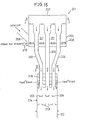
- FIG. 15 -19 there is shown an embodiment of the inventive mixing apparatus 201.
- the mixing apparatus 201 shown in FIG. 15 comprises essentially a distributing device 203, a plurality of standpipes 202 each having an upper potion extending vertically through the bottom of and up to the upper section of a distributing device 203, a mixing section 204 into which catalyst particles flow downwardly from the standpipes each having the lower portion into the mixing section 204, a plurality of plates 205 disposed in the mixing section 204 and below the lower part of the standpipes to disperse the particles fed therefrom in the radial direction and a fluid-feed chamber 206 disposed in the mixing section to spray a fluid such as a feedstock (heavy oil) so as to mix the same with the particles.
- a fluid such as a feedstock (heavy oil)
- the distributing device 203 is not restricted to the construction if it can distribute particles uniformly into the standpipes. In the embodiment shown in FIG. 15, fluidized bed is used to distribute the particles.
- the distributing device 203 includes a chamber 207 which is vertical and may be round, polygonal or rectangle in a cross-section.
- the chamber 207 in FIG. 15 is cylindrical and provided in the lower portion with a porous-plate type distributor or a pipe grid distributor.
- a porous plate 208 is employed.
- the side wall of the chamber 207 is connected with a feed pipe for feeding particles of such as a silica-alumina catalyst having a diameter of 1-50 ⁇ m and heated at a temperature of 450-700°C to the porous plate.
- the lower portion of the chamber 207 is connected with a fluidized gas feed pipe 210 for feeding a fluid gas such as steam, air or inactive gas through the porous plate 208 into the chamber 207 to fluidize the particles so as to form a fluidized particle bed 211.
- a fluid gas such as steam, air or inactive gas
- Each of the plurality of standpipes 202 extends vertically through the bottom of the chamber 207 and the porous plate 208 and has an upper tip extending as far as the mid-section of the chamber 207.
- the standpipes are disposed 3 to 30, preferably 3 to 7 in numbers.
- the standpipes should be arranged at certain intervals in the chamber 207. In FIG. 16, for instance, there are disposed seven pieces of the standpipes, six of which are arranged to be spaced equally apart (60°) in the circumferential direction and one of which is arranged to be on the center.
- the diameter of each stands pipes 202 is selective depending upon the feed rate of particles. However, needless to mention, under the conditions that the diameter of a reactor 212 described hereinafter and the number of the stand pipes are constant, the diameter thereof is increased with the feed rate of particles increased and decreased with the feed rate of the same reduced.
- the flow ratio of a catalyst to an oil is in the range of 5 - 50, preferably 20 - 30.
- the ratio less than 5 would result in an insufficient reaction due to a reduction in contacting time.
- the ratio exceeding 50 would involve a problem such as pressure loss and erosion.
- the mixing section 204 Disposed below the chamber 207 is a mixing section 204 for mixing a feedstock and the catalyst particles into which the lower tip of each of the stand pipes extends as far as the upper portion of the mixing section 204. Therefore, the fluidized particles pass through the mixing section 204 downwardly.
- the mixing section 204 is in the form of a cylinder and connected at the lower portion with a reactor 212 (vertical downward-flow type reactor) having the same diameter as that of the mixing section.
- the plurality of plates 205 for dispersing the particles flowing from the stand pipes 203 in the circumferential direction are disposed therebelow and in the middle section of the mixing section 204. These plates 205 are arranged at the same horizontal level.
- the plates may be in the shape of a disk having a diameter which is the same as or larger than that of the lower end of the stand pipe or having the center recessed lower than the level of the outer periphery, a dish-shape disk or a cone.
- these plates there are disposed another plurality of plates 213 for further dispersing the particles falling down from the dispersing plates 205, at the same horizontal level.
- These dispersing plates 213 should be arranged in such a position that the particles flow densely, for which instance the dispersing plates 213 are arranged below the spaces between the dispersing plates 205 as shown in FIG.15.
- the dispersing plates may be those which are the same as or different from the dispersing plates 205 located in the upper stream.
- the dispersing plates 205 and 213 are arranged in a single tier, respectively. Preferred number of tiers is within the range of 1 to 5, because too many tiers could increase mixing efficiency but result in pressure loss.
- a fluid-feed chamber 206 is provided in the mixing chamber in surround relation to the outer periphery of the stand pipes 202 to spray a feedstock such as a heavy oil.
- a feedstock such as a heavy oil.
- the chamber 206 is not restricted to its structure.
- the spraying angle is selective from 0 (horizontal direction) to 90°C (vertical direction) as shown in FIGS. 15 and 18. More specifically, the fluid-feed chamber 206 in FIG. 15 is constructed to spray a feedstock downwardly in close proximity of and in parallel relation to the outer periphery of the particles flowing cylindrically from the stand pipes so that the sprayed feedstock comes into contact with particles after being dispersed by the plates 205 and 213.
- the fluid-feed chamber 206 sprays a feedstock at an angle of 0°, i.e. in parallel with respect to a horizontal level by using a spraying medium such as gas and steam.
- the fluid-chamber 206 is also provided with an insulating means 214 as shown in FIG. 18.
- trays 215-218 which contain a steam for thermal insulation, a steam for spraying, a feedstock and a steam for thermal insulation and spraying, respectively.
- These trays 215- 218 are arranged in vertically superposed relation to one after another and in surround relation to the stand pipes. Therefore, the stand pipes extend through these trays 215-218.
- a partition 220 for thermal insulation Disposed below the thermal-insulating and spraying steam tray 218 is a partition 220 for thermal insulation extending in a horizontal direction and formed to be directed to the lower ends of the stand pipes. More specifically, this partition 220 is in the form of a disk provided with circular openings at the positions in conforming with the lower ends of the stand pipes.
- a clearance 221 is provided between the partition 220 and the thermal insulating and spraying steam tray 218 such that the steam therefrom flows through the clearance 221 inwardly in the radial direction to thermally insulate the inside of the mixing section and the feedstock fed from the feedstock tray 217.
- the insulating means 214 is constituted by the trays 215 and 218. The insulating means 214 is not restricted to its construction as long as it can thermally insulate a feedstock from the heat of the stand pipes.
- a cylindrical spraying chamber 222 is provided around the space 219, the upper portion of which chamber is communicated with the spraying steam chamber 216 so that the steam of a spraying medium therefrom can flow downwardly through the chamber 222 at high velocity.
- a multiplicity of spraying nozzles 223 are provided on the side wall of the feedstock tray 217 so that the feedstock therefrom is sprayed into the spraying chamber 222 to be mixed with steam.
- the resulting mixture collides with the thermal insulating partitions 221 and then flows horizontally over the entire cuter periphery of the particles fed from the stand pipes.
- the mixture is sprayed at an angle ranging from 0° (horizontally) to 90° (vertically), preferably from 0° to 45°.
- This angle can be varied by altering the angle of the pertition 220.
- the mixture in the embodiment shown in FIG. 18, the mixture is sprayed at an angle of 0°, i.e. horizontally.
- a plurality of spraying nozzle 223 are disposed at certain intervals in the circumferential direction to spray a feedstock entirely to the spraying chamber.
- the number of tiers on which each plurality of spraying nozzles 223 are disposed, spaced equally apart vertically, is selective within the range between 1 and 6, preferably 1 and 3.
- Catalyst particles are fed continuously onto the porous plate 208 through the feed pipes 209 and then fluidized by fluid gas to be formed into the fluidized bed 211.
- the particles fed excessively on a particular spot can be dispersed toward a part on which has less particles while being fluidized so that the particles can be dispersed in uniform density in a horizontal direction.
- the fluidized particles bed becomes increased in height, a part of the particles flows into the stand pipes 202 beyond the upper edges thereof from the all circumferential direction. Since the particles uniformed in density in a horizontal direction in such a manner are increased in height and then flows into the plurality of stand pipes, the particles in an equal amount can be distributed into each of the stand pipes.
- the particles in each of the stand pipes flow downwardly through the lower opening to the mixing section 204.
- the particles further flow down consecutively in the mixing section 204.
- the particles thus flow in the form of a cylinder although depending on the amount of the particles. Therefore, almost all the particles collide with the dispersing plates 205 and then dispersed in the outer radial direction.
- the particles are piled up thereon in the form of a cone widened downwardly and having an angle of response of around 20° as indicated by dot-lines in FIG. 18 so that the particles falling onto the piles fall along the slopes thereof outwardly in the radial direction.
- the particles collecting in the middle of the plates 205 function as a cushion to absorb the impact exerted by the particles falling from the stand pipes, leading to an advantage with respect to erosion.
- the dispersion of the particles is conducted in an effective manner by dispersing the particles falling from the plurality of the stand pipes with the corresponding plates outwardly in the radial direction.
- a feedstock is sprayed vertically from the fluid-feed chamber 206 in close proximity of and in surrounding relation to the outer periphery of the particle fed cylindrically from each of the stand pipes.
- the feedstock can be sprayed without coking due to the insulating means 214 provided in the fluid-feed chamber 206 which can thermally insulate the feed stock from the catalyst particles heated at a temperature of 450 - 700°.
- the feedstock sprayed in this manner is then collided with the particles dispersed outwardly in the radial direction and further finely scattered by impact upon the collision so that the feedstock can be mixed uniformly and rapidly with the particles.
- the resulting mixture is improved in contact efficiencies and the vaporization of the feedstock can be effected sufficiently.
- the particles are further dispersed and come to contact (collide) with the feedstock, resulting in further enhancement of contact efficiency leading to the mixture effected in a satisfactory manner.
- the resulting mixture flows downwardly into the reactor 212.
- a steam fed from the spraying steam tray 216 flows into the upper portion of the spraying chamber 222 and then flows downwardly thereinside at high velocity and at the same time the feedstock in the feedstock tray 217 is sprayed into the spraying chamber 222 to be mixed with the steam therein.
- the mixture is brought into collision with the partition 221 and sprayed together with the steam fed from the thermal insulating and spraying steam tray 218 over the entire outer periphery of the particles fed in the form of a cylinder from each of the stand pipe in a horizontal direction. Namely, the feedstock is sprayed at right angle with respect to the flow direction of the particles fed cylindrically from each of the stand pipes 202.
- the feedstock sprayed in this manner is further fined by the collision with the particles fed cylindrically and then flows downwardly after being scattered to the neighborhood of the outer periphery of the particles.
- the particles are dispersed in the outer radial direction by the dispersing plates 205 and collide again with the fined feed stock so that the feedstock is further finely scattered, leading to an efficient dispersion of the feed stock.
- the catalyst particles and the feedstock can be mixed uniformly and rapidly and contacted each other efficiently because the catalyst particles are distributed evenly to the plurality of stand pipes 202 and dispersed by the dispersing plates after passing through the stand pipes 202 and the feedstock comes into contact with the dispersed particles and then finely scattered.
- the inventive apparatus is applicable to the case where the catalyst particles is used in the larger proportion to the feedstock, maximumly 50 in the ratio therebetween.
- the contact reaction can be conducted uniformly for an extremely short period of time due to the capability of reduction in time (approximately 0.1 to 1.5 second) for contacting a feedstock with catalyst particles such that unfavorable excess cracking reaction can be avoided, leading to the capability of the production of a gasoline enhanced in quality.
- Apparatus F An apparatus (Apparatus F) in the form as shown in FIG. 18 which was made from transparent vinyl chloride.
- the principal dimensions of this apparatus are shown in Table 3.
- the experimental conditions were established on the assumption that mixing and gasification had just completed by spraying a feedstock to catalyst particles heated at a temperature of 600°C but the reaction had not occurred yet.
- the experimental conditions based on the assumption were changed in a feed rate of catalyst from 50 kg/min to 350 kg/min and a feed rate of air from 20 m 3 /h to 120 m 3 /h.
- the air was fed by from the second, third and forth spraying nozzles arranged vertically in tiers with the feed rate of each of the nozzles varied.
- the mixability was observed by using a video camera and viewing.
- Example 9 The feed rates of particles and air were one fifteenth of those in Example 9 to be conformity with the ratio of the sectional area of the Apparatus F to that of the model.
- the mixability was observed by using a video camera and by viewing as well as Example 9. The results were as follows:
Landscapes
- Chemical & Material Sciences (AREA)
- Chemical Kinetics & Catalysis (AREA)
- Organic Chemistry (AREA)
- Oil, Petroleum & Natural Gas (AREA)
- Engineering & Computer Science (AREA)
- General Chemical & Material Sciences (AREA)
- Dispersion Chemistry (AREA)
- Combustion & Propulsion (AREA)
- Devices And Processes Conducted In The Presence Of Fluids And Solid Particles (AREA)
- Production Of Liquid Hydrocarbon Mixture For Refining Petroleum (AREA)
Description
- This invention relates to an apparatus for mixing a fluid such as a heavy oil and particles such as a catalyst heated at elevated temperatures.
- There are known a reaction system in which solid particles as a catalyst or a heat medium is brought into contact with a reactant. A moving bed type reactor is a typical example of such reaction system which reactor is classified into one utilizing a concentrated fluidized bed (bubbles-fluidized bed) and the other utilizing a high-speed moving bed (fluidized bed). The high-velocity moving bed is used for a reaction in which a solid and a gas must come into contact for a short period of time. Currently, there has been mainly employed an upflow-type high velocity moving bed reactor so-called "riser-type" in a fluid catalytic cracking apparatus used for the production of a gasoline from a feedstock such as a heavy oil. This reactor is capable of reducing contact time with an improvement of a catalyst in ability, leading to an enhancement of selectivity of a final product and suppression in unfavorable excessive cracking reaction.
- US-A-4,323,314 discloses an apparatus for adding a liquid component to a pourable powdered or granular material, suitable for mixing a fluid with catalyst particles, in which the pourable material is supplied over a deflector, after which it trickles downwards in the form of a hollow cylindrical stream, falling freely, and is sprayed with the liquid components by means of at least one nozzle as it falls.
- DE-A-1,036,217 discloses an apparatus for cracking hydrocarbons with a short contacting time comprising a cylindrical vessel, a fluidized bed disposed above the vessel for feeding a continuous stream of fluidized particles to the reaction vessel, two cylindrical slots in the bottom of the fluidized bed for forming two concentrical and hollow cylindrical streams falling downs through the reaction vessel, one central nozzle to spray the inner side of the internal cylindrical particle stream with liquid and four nozzles disposed in the vessel wall to spray the outer surface of the external cylindrical particle stream with liquid. However, the nozzles are arranged to spray a particle stream with a liquid from horizontal or transverse direction with respect to said particle stream.
- Recently, a strong demand has been made for an enhancement in selective productivity of a gasoline or a light olefin and an investigation has been conducted for use of a downflow type high velocity moving bed reactor which is free from backmixing affecting adversely an improvement of the selectivity.
- Upon production of a gasoline from a feedstock such as a heavy oil using a fluid catalytic cracking apparatus equipped with the existing upflow-type reactor having a high speed moving bed, the contact reaction therein takes several seconds. Whereas upon production of a light olefin the reaction time is required to be reduced in the order of ranging from 0.1 to 1.5 seconds. A rapid mixture of a feed stock and a catalyst and vaporization thereof at the inlet port of a reactor is indispensable in order to conduct the contact reaction in a short period of time. Furthermore, it has become necessary to increase a recycle ratio of a catalyst to an oil to compensate for a reduction in conversion involved with a shortened reaction time. From view of this background, there has been demanded an apparatus which is capable of rapid mixture and vaporization of the feed stock and the catalyst at the inlet of the existing upflow type reactor forming a high speed moving bed and enables a recycle ratio of a catalyst to an oil as several times as greater than that (catalyst / oil ratio of 5 - 8) of a catalytic cracking apparatus for producing a gasoline from a feedstock such as a heavy oil.
- With the foregoing difficulties of the prior art in view, the present invention seeks to provide an apparatus which is capable of mixing a fluid and a solid particle uniformly and rapidly.
- According to the invention, there is provided an apparatus for mixing the fluid of a feedstock such as a heavy oil and the particles of a catalyst gasifying the fluid which comprises:
- a plurality of stand pipes extending vertically,
- a distributing device connected to each upper portion of said pipes for distributing uniformly the particles introduced into said device, into each of said pipes,
- a mixing section positioned below said distributing device and connected to each lower portion of said pipes extending from the device,
- a plurality of dispersing plates arranged in said mixing section and below each of said stand pipes for dispersing the particles falling there from outwardly in a radial direction and
- a fluid feed chamber arranged in said mixing section in surround relation to the outer periphery of each of the stand pipes to spray the fluid over the entire outer periphery of the cylindrical particles falling from each of the stand pipes.
- It is necessary for a short contact reaction to conduct a rapid uniform mixture of and vaporization of a feed stock and particles (catalyst) at the inlet of a reactor. Therefore, it is required to supply a feed stock in the form of fine droplet, for example by means of spray and to disperse uniformly a catalyst in the form of solid particles. The uniform mixture can be effected in a wide space but fails to be fully accomplished in a limited space. An extensive research and development to seek an alternative for solving the problem results in the following conclusion.
- In this alternative solution, after a feedstock in droplet form is fined tc some extent by means of a spray nozzle, the sprayed feedstock is brought into collision with solid particles so as to be further fined by impact caused by the collision. Importantly, solid particles are increased in surface area as large as possible so that the surface thereof can entirely collide with the sprayed feedstock. Hereinafter, it is described as to what kind of shape the particles take to have a large surface area in a limited size of space.
- The above and other features and advantages of the invention will be better understood from reading the following detailed description with reference to the accompanying drawings.
- FIG. 15 is a sectional view of an apparatus embodying the invention.
- FIG. 16 is a cross sectional view taken along the line A - A of FIG. 15.
- FIG. 17 is a cross sectional view taken along the line B - B of FIG. 15.
- FIG. 18 is a schematic view of main portion of an apparatus according to the invention.
- FIG. 19 is cross sectional view taken along the line C - C of FIG. 18.
- Referring now to FIG. 15 -19, there is shown an embodiment of the
inventive mixing apparatus 201. - The
mixing apparatus 201 shown in FIG. 15 comprises essentially adistributing device 203, a plurality ofstandpipes 202 each having an upper potion extending vertically through the bottom of and up to the upper section of adistributing device 203, amixing section 204 into which catalyst particles flow downwardly from the standpipes each having the lower portion into themixing section 204, a plurality ofplates 205 disposed in themixing section 204 and below the lower part of the standpipes to disperse the particles fed therefrom in the radial direction and a fluid-feed chamber 206 disposed in the mixing section to spray a fluid such as a feedstock (heavy oil) so as to mix the same with the particles. - The distributing
device 203 is not restricted to the construction if it can distribute particles uniformly into the standpipes. In the embodiment shown in FIG. 15, fluidized bed is used to distribute the particles. - The
distributing device 203 includes achamber 207 which is vertical and may be round, polygonal or rectangle in a cross-section. Thechamber 207 in FIG. 15 is cylindrical and provided in the lower portion with a porous-plate type distributor or a pipe grid distributor. In this embodiment, aporous plate 208 is employed. The side wall of thechamber 207 is connected with a feed pipe for feeding particles of such as a silica-alumina catalyst having a diameter of 1-50 µm and heated at a temperature of 450-700°C to the porous plate. The lower portion of thechamber 207 is connected with a fluidized gas feed pipe 210 for feeding a fluid gas such as steam, air or inactive gas through theporous plate 208 into thechamber 207 to fluidize the particles so as to form afluidized particle bed 211. Each of the plurality ofstandpipes 202 extends vertically through the bottom of thechamber 207 and theporous plate 208 and has an upper tip extending as far as the mid-section of thechamber 207. - Although not restricted, the standpipes are disposed 3 to 30, preferably 3 to 7 in numbers. The standpipes should be arranged at certain intervals in the
chamber 207. In FIG. 16, for instance, there are disposed seven pieces of the standpipes, six of which are arranged to be spaced equally apart (60°) in the circumferential direction and one of which is arranged to be on the center. The diameter of eachstands pipes 202 is selective depending upon the feed rate of particles. However, needless to mention, under the conditions that the diameter of areactor 212 described hereinafter and the number of the stand pipes are constant, the diameter thereof is increased with the feed rate of particles increased and decreased with the feed rate of the same reduced. The flow ratio of a catalyst to an oil is in the range of 5 - 50, preferably 20 - 30. The ratio less than 5 would result in an insufficient reaction due to a reduction in contacting time. The ratio exceeding 50 would involve a problem such as pressure loss and erosion. - Disposed below the
chamber 207 is amixing section 204 for mixing a feedstock and the catalyst particles into which the lower tip of each of the stand pipes extends as far as the upper portion of themixing section 204. Therefore, the fluidized particles pass through themixing section 204 downwardly. Themixing section 204 is in the form of a cylinder and connected at the lower portion with a reactor 212 (vertical downward-flow type reactor) having the same diameter as that of the mixing section. - The plurality of
plates 205 for dispersing the particles flowing from thestand pipes 203 in the circumferential direction are disposed therebelow and in the middle section of themixing section 204. Theseplates 205 are arranged at the same horizontal level. Although not restricted, the plates may be in the shape of a disk having a diameter which is the same as or larger than that of the lower end of the stand pipe or having the center recessed lower than the level of the outer periphery, a dish-shape disk or a cone. - Furthermore below these plates there are disposed another plurality of
plates 213 for further dispersing the particles falling down from the dispersingplates 205, at the same horizontal level. These dispersingplates 213 should be arranged in such a position that the particles flow densely, for which instance the dispersingplates 213 are arranged below the spaces between the dispersingplates 205 as shown in FIG.15. The dispersing plates may be those which are the same as or different from the dispersingplates 205 located in the upper stream. In FIG. 15, the dispersingplates - A fluid-
feed chamber 206 is provided in the mixing chamber in surround relation to the outer periphery of thestand pipes 202 to spray a feedstock such as a heavy oil. As long as the fluid-feed chamber 206 sprays a feedstock over the entire outer periphery of particles flowing in the form of such as a cylinder, thechamber 206 is not restricted to its structure. The spraying angle is selective from 0 (horizontal direction) to 90°C (vertical direction) as shown in FIGS. 15 and 18. More specifically, the fluid-feed chamber 206 in FIG. 15 is constructed to spray a feedstock downwardly in close proximity of and in parallel relation to the outer periphery of the particles flowing cylindrically from the stand pipes so that the sprayed feedstock comes into contact with particles after being dispersed by theplates - In FIG. 18, the fluid-
feed chamber 206 sprays a feedstock at an angle of 0°, i.e. in parallel with respect to a horizontal level by using a spraying medium such as gas and steam. - The fluid-
chamber 206 is also provided with an insulatingmeans 214 as shown in FIG. 18. In the upper portion of themixing section 204, there is provided with trays 215-218 which contain a steam for thermal insulation, a steam for spraying, a feedstock and a steam for thermal insulation and spraying, respectively. These trays 215- 218 are arranged in vertically superposed relation to one after another and in surround relation to the stand pipes. Therefore, the stand pipes extend through these trays 215-218. Between the superimposed trays 215 - 218 and the outer periphery of each of the stand pipes, there is provided small cylindrical spaces orclearances 219 the upper portion of which is communicated with the thermalinsulation steam tray 215 so that a thermal insulating steam flows downwardly along the outer periphery of each of thestand pipes 202 so as to effect thermal insulation of a feedstock from heat of the stand pipes. - Disposed below the thermal-insulating and spraying
steam tray 218 is apartition 220 for thermal insulation extending in a horizontal direction and formed to be directed to the lower ends of the stand pipes. More specifically, thispartition 220 is in the form of a disk provided with circular openings at the positions in conforming with the lower ends of the stand pipes. Aclearance 221 is provided between thepartition 220 and the thermal insulating and sprayingsteam tray 218 such that the steam therefrom flows through theclearance 221 inwardly in the radial direction to thermally insulate the inside of the mixing section and the feedstock fed from thefeedstock tray 217. The insulating means 214 is constituted by thetrays - A
cylindrical spraying chamber 222 is provided around thespace 219, the upper portion of which chamber is communicated with the sprayingsteam chamber 216 so that the steam of a spraying medium therefrom can flow downwardly through thechamber 222 at high velocity. A multiplicity of sprayingnozzles 223 are provided on the side wall of thefeedstock tray 217 so that the feedstock therefrom is sprayed into the sprayingchamber 222 to be mixed with steam. The resulting mixture collides with the thermal insulatingpartitions 221 and then flows horizontally over the entire cuter periphery of the particles fed from the stand pipes. The mixture is sprayed at an angle ranging from 0° (horizontally) to 90° (vertically), preferably from 0° to 45°. This angle can be varied by altering the angle of thepertition 220. in the embodiment shown in FIG. 18, the mixture is sprayed at an angle of 0°, i.e. horizontally. As shown in FIG. 19, a plurality of sprayingnozzle 223 are disposed at certain intervals in the circumferential direction to spray a feedstock entirely to the spraying chamber. The number of tiers on which each plurality of sprayingnozzles 223 are disposed, spaced equally apart vertically, is selective within the range between 1 and 6, preferably 1 and 3. - The operation conducted by using the apparatus in FIG. 15 is now described hereinbelow.
- Catalyst particles are fed continuously onto the
porous plate 208 through thefeed pipes 209 and then fluidized by fluid gas to be formed into thefluidized bed 211. By forming thefluidized bed 211 in this way, the particles fed excessively on a particular spot can be dispersed toward a part on which has less particles while being fluidized so that the particles can be dispersed in uniform density in a horizontal direction. - As the fluidized particles bed becomes increased in height, a part of the particles flows into the
stand pipes 202 beyond the upper edges thereof from the all circumferential direction. Since the particles uniformed in density in a horizontal direction in such a manner are increased in height and then flows into the plurality of stand pipes, the particles in an equal amount can be distributed into each of the stand pipes. - The particles in each of the stand pipes flow downwardly through the lower opening to the
mixing section 204. - The particles further flow down consecutively in the
mixing section 204. The particles thus flow in the form of a cylinder although depending on the amount of the particles. Therefore, almost all the particles collide with the dispersingplates 205 and then dispersed in the outer radial direction. For example, in the case of using theplate 205 in the form of a disk or a dish, the particles are piled up thereon in the form of a cone widened downwardly and having an angle of response of around 20° as indicated by dot-lines in FIG. 18 so that the particles falling onto the piles fall along the slopes thereof outwardly in the radial direction. In the case of using the disk or dish likeplates 205 having the depressed center, the particles collecting in the middle of theplates 205 function as a cushion to absorb the impact exerted by the particles falling from the stand pipes, leading to an advantage with respect to erosion. - Therefore, the dispersion of the particles is conducted in an effective manner by dispersing the particles falling from the plurality of the stand pipes with the corresponding plates outwardly in the radial direction.
- In the embodiment shown in FIG. 15, a feedstock is sprayed vertically from the fluid-
feed chamber 206 in close proximity of and in surrounding relation to the outer periphery of the particle fed cylindrically from each of the stand pipes. Whereupon, the feedstock can be sprayed without coking due to the insulating means 214 provided in the fluid-feed chamber 206 which can thermally insulate the feed stock from the catalyst particles heated at a temperature of 450 - 700°. - The feedstock sprayed in this manner is then collided with the particles dispersed outwardly in the radial direction and further finely scattered by impact upon the collision so that the feedstock can be mixed uniformly and rapidly with the particles. The resulting mixture is improved in contact efficiencies and the vaporization of the feedstock can be effected sufficiently. Furthermore, due to the plurality of the
dispersion plates reactor 212. - In the fluid-
feed chamber 206 constructed as shown in FIG. 18, a steam fed from the sprayingsteam tray 216 flows into the upper portion of the sprayingchamber 222 and then flows downwardly thereinside at high velocity and at the same time the feedstock in thefeedstock tray 217 is sprayed into the sprayingchamber 222 to be mixed with the steam therein. The mixture is brought into collision with thepartition 221 and sprayed together with the steam fed from the thermal insulating and sprayingsteam tray 218 over the entire outer periphery of the particles fed in the form of a cylinder from each of the stand pipe in a horizontal direction. Namely, the feedstock is sprayed at right angle with respect to the flow direction of the particles fed cylindrically from each of thestand pipes 202. - The feedstock sprayed in this manner is further fined by the collision with the particles fed cylindrically and then flows downwardly after being scattered to the neighborhood of the outer periphery of the particles. The particles are dispersed in the outer radial direction by the dispersing
plates 205 and collide again with the fined feed stock so that the feedstock is further finely scattered, leading to an efficient dispersion of the feed stock. - Therefore, the catalyst particles and the feedstock can be mixed uniformly and rapidly and contacted each other efficiently because the catalyst particles are distributed evenly to the plurality of
stand pipes 202 and dispersed by the dispersing plates after passing through thestand pipes 202 and the feedstock comes into contact with the dispersed particles and then finely scattered. The inventive apparatus is applicable to the case where the catalyst particles is used in the larger proportion to the feedstock, maximumly 50 in the ratio therebetween. - Furthermore, the contact reaction can be conducted uniformly for an extremely short period of time due to the capability of reduction in time (approximately 0.1 to 1.5 second) for contacting a feedstock with catalyst particles such that unfavorable excess cracking reaction can be avoided, leading to the capability of the production of a gasoline enhanced in quality.
- The invention will be further described by way of the following examples which are provided only for illustrative purposes.
- There was used an apparatus (Apparatus F) in the form as shown in FIG. 18 which was made from transparent vinyl chloride. The principal dimensions of this apparatus are shown in Table 3.
- There were used particles of a catalyst generally used in a flowing catalytic cracking apparatus producing a gasoline from a heavy oil. The catalyst was 63 microns in an average particle size and 0.85 g/cm3 in a bulking density. Air at normal temperature was used as a fluid to be sprayed instead of a feed stock.
- The experimental conditions were established on the assumption that mixing and gasification had just completed by spraying a feedstock to catalyst particles heated at a temperature of 600°C but the reaction had not occurred yet. The experimental conditions based on the assumption were changed in a feed rate of catalyst from 50 kg/min to 350 kg/min and a feed rate of air from 20 m3/h to 120 m3/h. The air was fed by from the second, third and forth spraying nozzles arranged vertically in tiers with the feed rate of each of the nozzles varied. The mixability was observed by using a video camera and viewing.
- There were conducted the above-described experiments using Apparatus F and the results thereof were as follows:
- (1) It was observed that the catalyst particles from the dispersing device flowed uniformly into the stand pipes disposed seven in number.
- (2) The mixability was fairy excellent due to the provision of the dispersing plates although the air was only fed from the feed chamber but not fed form the tray.
- (3) The dispersion of the particles was improved with the feed rate of air from the tray increased.
- (4) Under the conditions where the feed rate of air from each of the nozzles was constant, the mixability was improved with the feed rate of air from the forth nozzles increased.
- The experiments were conducted using the two-dimensional model of Apparatus F of which primary dimensions were the same as that of Apparatus F and were 1 cm in thick.
- The feed rates of particles and air were one fifteenth of those in Example 9 to be conformity with the ratio of the sectional area of the Apparatus F to that of the model. The mixability was observed by using a video camera and by viewing as well as Example 9. The results were as follows:
- (1) The particles from the feed chamber were flow uniformly into the stand pipes disposed seven in number. However, the particles mostly tended to flow the outside but not the center of the stand pipes when fed at a low rate.
- (2) Although the effect of the dispersing plates arranged in two tiers was recognized, the mixability was not satisfactory when the air was fed only from the feed chamber but not from the tray. The mixability was extremely improved with the feed rate of air from the tray increased.
- (3) The mixability was improved with the feed rate of air from the forth tray increased as well as Example 9.
- (4) The particles passed through the stand pipes fell onto the dispersing plates and were formed into a mountain having a response angle of around 20°. The dispersing plates used in this example were in the form of a shallow tray. The particles accumulated on the plates played a role as a cushion in absorbing the impact caused by the particles falling from the stand pipes. This is advantageous to avoid erosion.
| Dimensions of Apparatus | |
| Apparatus | |
| Diameter of Dispersing Device mm | 320 |
| Diameter of Standpipe mm | 30 |
| Diameter of Mixing Section mm | 160 |
| Diameter of Dispersing Plate mm | 30 |
| Diameter of Reactor mm | 160 |
| Diameter of Nozzle mm | 2 |
| Number of Nozzles (16x2x7) | 224 |
Claims (6)
- An apparatus (201) for mixing the fluid of a feedstock such as a heavy oil and the particles of a catalyst gasifying the fluid which comprises:a plurality of stand pipes (202) extending vertically,a distributing device (203) connected to each upper portion of said pipes for distributing uniformly the particles introduced into said device, into each of said pipes (202),a mixing section (204) positioned below said distributing device (203) and connected to each lower portion of said pipes extending from the device,a plurality of dispersing plates (205) arranged in said mixing section and below each of said stand pipes for dispersing the particles falling there from outwardly in a radial direction anda fluid feed chamber (206) arranged in said mixing section in surround relation to the outer periphery of each of the stand pipes to spray the fluid over the entire outer periphery of the cylindrical particles falling from each of the stand pipes.
- The apparatus (201) according to claim 1 wherein the fluid feed chamber (206) is arranged in said mixing section in surround relation to the outer periphery of each of the stand pipes to spray the fluid downwardly in a vertical direction in close proximity of and in surround relation to the entire outer periphery of the cylindrical particles falling from each of the stand pipes so as to collide with the particles after being dispersed by the plates.
- The apparatus (201) according to claim 1 or 2 wherein said fluid feed section is a spraying device for spraying the fluid using a spray medium such as steam and air.
- The apparatus (201) according to any one of the preceding claims wherein a thermal insulating means (214) is provided in surrounding relation to said stand pipes to prevent the fluid sprayed from being affected by the heat of the particles heated at a temperature of over 300°C in the stand pipes.
- The apparatus (201) according to claim 4 wherein a disc shape plate (220) is disposed below said thermal insulation means and has openings just under the lower ends of the stand pipes.
- The apparatus (201) according to claim 1 or 2 wherein said mixing section (204) is provided below said plates with another plurality of plates (213) for further dispersing the particles dispersed by said upper plates (205), disposed at least where the particles fall in an increased density.
Applications Claiming Priority (5)
| Application Number | Priority Date | Filing Date | Title |
|---|---|---|---|
| JP08237297A JP3662709B2 (en) | 1997-03-14 | 1997-03-14 | Mixing equipment |
| JP8237297 | 1997-03-14 | ||
| JP8237397 | 1997-03-14 | ||
| JP08237397A JP3662710B2 (en) | 1997-03-14 | 1997-03-14 | Mixing equipment |
| EP98850038A EP0864633B1 (en) | 1997-03-14 | 1998-03-16 | Apparatus for mixing feed stock and catalyst particles |
Related Parent Applications (1)
| Application Number | Title | Priority Date | Filing Date |
|---|---|---|---|
| EP98850038A Division EP0864633B1 (en) | 1997-03-14 | 1998-03-16 | Apparatus for mixing feed stock and catalyst particles |
Publications (2)
| Publication Number | Publication Date |
|---|---|
| EP1352945A1 EP1352945A1 (en) | 2003-10-15 |
| EP1352945B1 true EP1352945B1 (en) | 2006-08-02 |
Family
ID=26423407
Family Applications (2)
| Application Number | Title | Priority Date | Filing Date |
|---|---|---|---|
| EP03015250A Expired - Lifetime EP1352945B1 (en) | 1997-03-14 | 1998-03-16 | Apparatus for mixing feedstock and catalyst particles |
| EP98850038A Expired - Lifetime EP0864633B1 (en) | 1997-03-14 | 1998-03-16 | Apparatus for mixing feed stock and catalyst particles |
Family Applications After (1)
| Application Number | Title | Priority Date | Filing Date |
|---|---|---|---|
| EP98850038A Expired - Lifetime EP0864633B1 (en) | 1997-03-14 | 1998-03-16 | Apparatus for mixing feed stock and catalyst particles |
Country Status (4)
| Country | Link |
|---|---|
| US (2) | US6186658B1 (en) |
| EP (2) | EP1352945B1 (en) |
| KR (1) | KR100524623B1 (en) |
| CN (2) | CN1116922C (en) |
Families Citing this family (38)
| Publication number | Priority date | Publication date | Assignee | Title |
|---|---|---|---|---|
| CN1116922C (en) * | 1997-03-14 | 2003-08-06 | 日石三菱株式会社 | a mixing device |
| ES2247849T3 (en) * | 1998-12-29 | 2006-03-01 | PIRELLI & C. S.P.A. | PROCEDURE AND APPLIANCE TO CONTINUOUSLY CONTINUE A LIQUID PHASE SUBSTANCE IN PLASTIC GRANULES. |
| BR9905840B1 (en) * | 1999-12-14 | 2010-07-13 | load dispersing system of fluid catalytic cracking units. | |
| BR0101433B1 (en) * | 2001-04-10 | 2011-02-22 | multi-functional input method and device for downflow tubular reactor. | |
| US6663596B2 (en) | 2001-08-13 | 2003-12-16 | Scimed Life Systems, Inc. | Delivering material to a patient |
| US7045103B2 (en) * | 2003-01-13 | 2006-05-16 | Exxonmobil Research And Engineering Company | Multiphase mixing device with baffles |
| US7052654B2 (en) * | 2003-02-05 | 2006-05-30 | Exxonmobile Research And Engineering Company | Multiphase mixing device with staged gas introduction |
| US7074371B2 (en) * | 2003-05-16 | 2006-07-11 | Exxonmobil Research And Engineering Company | Multiphase mixing device with improved quench injection |
| US7074372B2 (en) * | 2003-05-16 | 2006-07-11 | Exxonmobil Research And Engineering Company | Multiphase mixing device with improved quench injection for inducing rotational flow |
| BRPI0405641B1 (en) * | 2004-02-10 | 2013-04-09 | apparatus and process for downward reactor fluid catalytic cracking. | |
| SG120172A1 (en) * | 2004-08-10 | 2006-03-28 | Beng Lai Koh | Mixing apparatus |
| JP2007120755A (en) * | 2005-09-29 | 2007-05-17 | Mitsubishi Heavy Ind Ltd | Pipe including fluid mixing zone |
| US20070264435A1 (en) * | 2006-05-10 | 2007-11-15 | Kenrick Venett | Material processing system through an injection nozzle |
| WO2008002559A2 (en) * | 2006-06-26 | 2008-01-03 | Precision Combustion, Inc. | Streamlined flow mixer |
| JP4922685B2 (en) * | 2006-07-12 | 2012-04-25 | 財団法人 国際石油交流センター | Mixing equipment |
| TW200821125A (en) * | 2006-08-23 | 2008-05-16 | Sulzer Chemtech Ag | A metering device |
| US8827544B2 (en) * | 2007-03-15 | 2014-09-09 | Dow Global Technologies Llc | Mixer for continuous flow reactor, continuous flow reactor, method of forming such a mixer, and method of operating such a reactor |
| ITMI20070627A1 (en) * | 2007-03-29 | 2008-09-30 | Polimeri Europa Spa | MIXING DEVICE LOW LOSS OF LOAD AND ITS USE IN THE MIXING OF TWO GAS-STEAMS |
| US20090251989A1 (en) * | 2007-06-26 | 2009-10-08 | Pfefferle William C | Streamlined flow mixer |
| US7901640B2 (en) * | 2008-05-13 | 2011-03-08 | Uop Llc | Optimized counter-current flow baffle |
| US7718146B2 (en) | 2008-05-13 | 2010-05-18 | Uop Llc | Enhanced bed separation in a styrene monomer reactor using milled plates |
| US7906081B2 (en) * | 2008-05-13 | 2011-03-15 | Uop Llc | Internal grids for adsorbent chambers and reactors |
| US8657483B2 (en) * | 2010-09-03 | 2014-02-25 | Cabot Norit Americas, Inc. | Apparatuses for dilute phase impregnation of a milled sorbent with a chemical compound in an aqueous solution |
| HUE026139T2 (en) * | 2011-03-11 | 2016-05-30 | Bayer Ip Gmbh | Mixing silo |
| JP5823911B2 (en) * | 2012-04-27 | 2015-11-25 | Jx日鉱日石エネルギー株式会社 | Mixing device for mixing raw material and catalyst in fluid catalytic cracking unit |
| CN102807282B (en) * | 2012-08-17 | 2013-12-18 | 甘肃银光化学工业集团有限公司 | Wet type raw material feeding device and method for feeding multiple raw materials |
| US9677019B2 (en) * | 2012-10-31 | 2017-06-13 | Thermochem Recovery International, Inc. | System and method for processing raw gas with in-situ catalyst regeneration |
| WO2015023439A1 (en) | 2013-08-12 | 2015-02-19 | United Technologies Corporation | High temperature fluidized bed for powder treatment |
| WO2015023438A1 (en) | 2013-08-12 | 2015-02-19 | United Technologies Corporation | Powder spheroidizing via fluidized bed |
| CN115957702A (en) * | 2015-03-13 | 2023-04-14 | 三菱化学株式会社 | Method for filling catalyst in fluidized bed reactor and method for producing nitrile compound |
| CN109589813A (en) * | 2018-12-07 | 2019-04-09 | 国电科学技术研究院有限公司 | Mix dispenser in more rotation jet stream whirlpools |
| CN109675455A (en) * | 2019-01-25 | 2019-04-26 | 江苏新美星包装机械股份有限公司 | Soda mixer |
| US11235301B1 (en) | 2020-07-16 | 2022-02-01 | Technip Process Technology, Inc. | Systems and methods for improving feed catalyst contacting in downflow reactors |
| CN114486584B (en) * | 2020-11-12 | 2024-09-13 | 国家能源投资集团有限责任公司 | Catalyst strength measuring device, nozzle and nozzle assembly |
| CN114849869B (en) * | 2022-06-09 | 2025-04-22 | 西北师范大学 | A catalyst fluidized attrition classification method |
| CN114870679B (en) * | 2022-06-14 | 2024-06-07 | 上海汉伟医疗器械有限公司 | Constant-temperature fat emulsification device and fat emulsification method thereof |
| CN116021660B (en) * | 2022-09-28 | 2025-01-21 | 青岛黑猫新材料研究院有限公司 | Mixer, device and mixing method for continuous production of natural rubber wet mixing |
| FR3140778B1 (en) * | 2022-10-13 | 2025-10-03 | Ifp Energies Now | Downward gas-solid co-current fluidized bed reactor with oriented injector. |
Family Cites Families (18)
| Publication number | Priority date | Publication date | Assignee | Title |
|---|---|---|---|---|
| US21819A (en) * | 1858-10-19 | Arrangement oe means eor making tight joints abound the faucets oe | ||
| US2534253A (en) * | 1942-02-27 | 1950-12-19 | Anderson Clayton & Co | Refining apparatus |
| US2446986A (en) * | 1944-04-08 | 1948-08-10 | Socony Vacuum Oil Co Inc | Apparatus for contacting gases with particle form solid material |
| US2662006A (en) * | 1953-01-16 | 1953-12-08 | Socony Vacuum Oil Co Inc | Gas manufacture |
| DE1036217B (en) | 1955-01-31 | 1958-08-14 | Bataafsche Petroleum | Method and device for achieving a rapid change in temperature of gases or liquids |
| US2949347A (en) * | 1958-06-13 | 1960-08-16 | Phillips Petroleum Co | Hydrocarbon conversion reaction vessel |
| US3071540A (en) | 1959-10-27 | 1963-01-01 | Kellogg M W Co | Oil feed system for fluid catalytic cracking unit |
| US3232590A (en) * | 1964-07-08 | 1966-02-01 | Us Stoneware Co | Treating tower having a plate for collecting, mixing and distributing liquid |
| BE715089A (en) | 1968-05-13 | 1968-09-30 | ||
| NO140968C (en) * | 1977-04-04 | 1979-12-19 | Dyno Industrier As | PLANT FOR MIXING POWDER-LIKE MATERIALS |
| CH628521A5 (en) | 1978-05-20 | 1982-03-15 | Kaiser Wirz Max | METHOD AND DEVICE FOR ADMINISTERING LIQUID COMPONENTS IN SCHUETTABLE GOETER. |
| US4919898A (en) * | 1987-08-11 | 1990-04-24 | Stone & Webster Engineering Corp. | Particulate solids cracking apparatus |
| FR2667609B1 (en) * | 1990-10-03 | 1993-07-16 | Inst Francais Du Petrole | PROCESS AND DEVICE FOR CATALYTIC CRACKING IN DOWNFLOW BED. |
| FR2669037A1 (en) * | 1990-11-08 | 1992-05-15 | Total France | METHOD AND APPARATUS FOR HOMOGENIZATION, WITHIN A TUBULAR CRACKING CRACK OF HYDROCARBONS BED OF FLUIDIZED SOLID PARTICLES, THE MIXTURE OF THESE PARTICLES AND HYDROCARBON VAPORS FOR TREATMENT. |
| NO911337D0 (en) * | 1991-04-05 | 1991-04-05 | Hans Hiorth | CONTROL DEVICE FOR CONTINUOUS STATIC THIN LAYER MIXTURES. |
| ES2079755T3 (en) * | 1991-09-09 | 1996-01-16 | Buehler Ag | DEVICE AND PROCEDURE FOR THE DOSAGE OF SOLID PRESENT IN A SOLID / GAS FLOW FROM A FLUIDIZED BED. |
| US5296131A (en) * | 1992-12-02 | 1994-03-22 | Mobil Oil Corporation | Process for short contact time cracking |
| CN1116922C (en) * | 1997-03-14 | 2003-08-06 | 日石三菱株式会社 | a mixing device |
-
1998
- 1998-03-13 CN CN98109688A patent/CN1116922C/en not_active Expired - Lifetime
- 1998-03-13 CN CNB021479364A patent/CN1243609C/en not_active Expired - Fee Related
- 1998-03-13 US US09/042,396 patent/US6186658B1/en not_active Expired - Lifetime
- 1998-03-14 KR KR1019980008676A patent/KR100524623B1/en not_active Expired - Fee Related
- 1998-03-16 EP EP03015250A patent/EP1352945B1/en not_active Expired - Lifetime
- 1998-03-16 EP EP98850038A patent/EP0864633B1/en not_active Expired - Lifetime
-
2000
- 2000-11-29 US US09/725,626 patent/US6612731B2/en not_active Expired - Lifetime
Also Published As
| Publication number | Publication date |
|---|---|
| EP1352945A1 (en) | 2003-10-15 |
| CN1436585A (en) | 2003-08-20 |
| US6612731B2 (en) | 2003-09-02 |
| US6186658B1 (en) | 2001-02-13 |
| US20010000024A1 (en) | 2001-03-15 |
| CN1116922C (en) | 2003-08-06 |
| CN1208668A (en) | 1999-02-24 |
| KR100524623B1 (en) | 2006-04-06 |
| CN1243609C (en) | 2006-03-01 |
| EP0864633A2 (en) | 1998-09-16 |
| EP0864633A3 (en) | 1998-12-23 |
| KR19980080275A (en) | 1998-11-25 |
| EP0864633B1 (en) | 2006-06-14 |
Similar Documents
| Publication | Publication Date | Title |
|---|---|---|
| EP1352945A1 (en) | Apparatus for mixing feedstock and catalyst particles | |
| US5462719A (en) | Method and apparatus for mixing and distributing fluids in a reactor | |
| US6387247B1 (en) | Feed injection system for catalytic cracking process | |
| US7112312B2 (en) | Quench box for a multi-bed, mixed-phase cocurrent downflow fixed-bed reactor | |
| US4683121A (en) | Reactor for non-isothermic reactions for the preparation of hydrocarbons | |
| US4669890A (en) | Mixing device for vertical flow fluid-solid contacting | |
| AU753170B2 (en) | Atomizing feed nozzle and method of use thereof | |
| EP2039418B1 (en) | Mixing apparatus | |
| US3502445A (en) | Apparatus for mixing fluids in concurrent downflow relationship | |
| US20010055548A1 (en) | Device for distributing a poly-phase mixture over a bed of a granular solid, comprising a porous jet disturber element | |
| US6146519A (en) | Gas solid contact riser with redistribution | |
| KR100504989B1 (en) | Atomizing nozzle and method of use thereof | |
| EP0813582B1 (en) | Feed nozzle assembly | |
| JP3776995B2 (en) | Hydrocarbon charge injection device | |
| WO1988004199A1 (en) | Fluidized bed | |
| JP3662709B2 (en) | Mixing equipment | |
| JP3662710B2 (en) | Mixing equipment | |
| US2500870A (en) | Hydrocarbon cracking process and apparatus using pebble heater with jet ejector | |
| US5501789A (en) | Process for improved contacting of hydrocarbon feedstock and particulate solids | |
| WO1984004584A1 (en) | Heat exchange between solids | |
| US7094380B1 (en) | Distribution apparatus for short time contact of hydrocarbon compounds with particles | |
| US2917455A (en) | Feed distributor for fluid reactants and particulate solids | |
| JPH0640949B2 (en) | Mixer for vertical flow fluid-solid contact | |
| US2575297A (en) | Process and apparatus for contacting fluid solids with gases | |
| JPS5966340A (en) | Stream distributing apparatus and system |
Legal Events
| Date | Code | Title | Description |
|---|---|---|---|
| PUAI | Public reference made under article 153(3) epc to a published international application that has entered the european phase |
Free format text: ORIGINAL CODE: 0009012 |
|
| 17P | Request for examination filed |
Effective date: 20030705 |
|
| AC | Divisional application: reference to earlier application |
Ref document number: 0864633 Country of ref document: EP Kind code of ref document: P |
|
| AK | Designated contracting states |
Kind code of ref document: A1 Designated state(s): FR GB |
|
| AX | Request for extension of the european patent |
Extension state: AL LT LV MK |
|
| RIN1 | Information on inventor provided before grant (corrected) |
Inventor name: NISHIDA, SYOZO Inventor name: FUJIYAMA, YULCHIRO |
|
| AKX | Designation fees paid |
Designated state(s): FR GB |
|
| 17Q | First examination report despatched |
Effective date: 20050613 |
|
| GRAP | Despatch of communication of intention to grant a patent |
Free format text: ORIGINAL CODE: EPIDOSNIGR1 |
|
| GRAS | Grant fee paid |
Free format text: ORIGINAL CODE: EPIDOSNIGR3 |
|
| GRAA | (expected) grant |
Free format text: ORIGINAL CODE: 0009210 |
|
| AC | Divisional application: reference to earlier application |
Ref document number: 0864633 Country of ref document: EP Kind code of ref document: P |
|
| AK | Designated contracting states |
Kind code of ref document: B1 Designated state(s): FR GB |
|
| REG | Reference to a national code |
Ref country code: GB Ref legal event code: FG4D |
|
| ET | Fr: translation filed | ||
| PLBE | No opposition filed within time limit |
Free format text: ORIGINAL CODE: 0009261 |
|
| STAA | Information on the status of an ep patent application or granted ep patent |
Free format text: STATUS: NO OPPOSITION FILED WITHIN TIME LIMIT |
|
| 26N | No opposition filed |
Effective date: 20070503 |
|
| REG | Reference to a national code |
Ref country code: FR Ref legal event code: PLFP Year of fee payment: 18 |
|
| PGFP | Annual fee paid to national office [announced via postgrant information from national office to epo] |
Ref country code: GB Payment date: 20150311 Year of fee payment: 18 Ref country code: FR Payment date: 20150309 Year of fee payment: 18 |
|
| GBPC | Gb: european patent ceased through non-payment of renewal fee |
Effective date: 20160316 |
|
| REG | Reference to a national code |
Ref country code: FR Ref legal event code: ST Effective date: 20161130 |
|
| PG25 | Lapsed in a contracting state [announced via postgrant information from national office to epo] |
Ref country code: GB Free format text: LAPSE BECAUSE OF NON-PAYMENT OF DUE FEES Effective date: 20160316 Ref country code: FR Free format text: LAPSE BECAUSE OF NON-PAYMENT OF DUE FEES Effective date: 20160331 |