EP1352620B1 - Prosthetic knee with limited sliding movement of tibial bearing - Google Patents
Prosthetic knee with limited sliding movement of tibial bearing Download PDFInfo
- Publication number
- EP1352620B1 EP1352620B1 EP03007963A EP03007963A EP1352620B1 EP 1352620 B1 EP1352620 B1 EP 1352620B1 EP 03007963 A EP03007963 A EP 03007963A EP 03007963 A EP03007963 A EP 03007963A EP 1352620 B1 EP1352620 B1 EP 1352620B1
- Authority
- EP
- European Patent Office
- Prior art keywords
- bearing
- control arm
- prosthesis
- component
- bearing surface
- Prior art date
- Legal status (The legal status is an assumption and is not a legal conclusion. Google has not performed a legal analysis and makes no representation as to the accuracy of the status listed.)
- Expired - Lifetime
Links
- 210000003127 knee Anatomy 0.000 title description 20
- 210000000629 knee joint Anatomy 0.000 claims description 5
- 239000007769 metal material Substances 0.000 claims 2
- 210000002303 tibia Anatomy 0.000 description 19
- 238000001356 surgical procedure Methods 0.000 description 18
- 210000000689 upper leg Anatomy 0.000 description 15
- 210000003041 ligament Anatomy 0.000 description 10
- 238000002513 implantation Methods 0.000 description 6
- 210000002967 posterior cruciate ligament Anatomy 0.000 description 6
- 208000006820 Arthralgia Diseases 0.000 description 3
- JJLJMEJHUUYSSY-UHFFFAOYSA-L Copper hydroxide Chemical compound [OH-].[OH-].[Cu+2] JJLJMEJHUUYSSY-UHFFFAOYSA-L 0.000 description 3
- 239000007943 implant Substances 0.000 description 3
- 208000024765 knee pain Diseases 0.000 description 3
- 210000001519 tissue Anatomy 0.000 description 3
- 230000002950 deficient Effects 0.000 description 2
- 210000004872 soft tissue Anatomy 0.000 description 2
- 208000002193 Pain Diseases 0.000 description 1
- 239000000853 adhesive Substances 0.000 description 1
- 230000001070 adhesive effect Effects 0.000 description 1
- 210000000988 bone and bone Anatomy 0.000 description 1
- 238000010276 construction Methods 0.000 description 1
- 230000000694 effects Effects 0.000 description 1
- 208000014674 injury Diseases 0.000 description 1
- 238000013150 knee replacement Methods 0.000 description 1
- 210000002414 leg Anatomy 0.000 description 1
- 238000011084 recovery Methods 0.000 description 1
- 230000008733 trauma Effects 0.000 description 1
Images


Classifications
-
- A—HUMAN NECESSITIES
- A61—MEDICAL OR VETERINARY SCIENCE; HYGIENE
- A61F—FILTERS IMPLANTABLE INTO BLOOD VESSELS; PROSTHESES; DEVICES PROVIDING PATENCY TO, OR PREVENTING COLLAPSING OF, TUBULAR STRUCTURES OF THE BODY, e.g. STENTS; ORTHOPAEDIC, NURSING OR CONTRACEPTIVE DEVICES; FOMENTATION; TREATMENT OR PROTECTION OF EYES OR EARS; BANDAGES, DRESSINGS OR ABSORBENT PADS; FIRST-AID KITS
- A61F2/00—Filters implantable into blood vessels; Prostheses, i.e. artificial substitutes or replacements for parts of the body; Appliances for connecting them with the body; Devices providing patency to, or preventing collapsing of, tubular structures of the body, e.g. stents
- A61F2/02—Prostheses implantable into the body
- A61F2/30—Joints
- A61F2/38—Joints for elbows or knees
- A61F2/3868—Joints for elbows or knees with sliding tibial bearing
-
- A—HUMAN NECESSITIES
- A61—MEDICAL OR VETERINARY SCIENCE; HYGIENE
- A61F—FILTERS IMPLANTABLE INTO BLOOD VESSELS; PROSTHESES; DEVICES PROVIDING PATENCY TO, OR PREVENTING COLLAPSING OF, TUBULAR STRUCTURES OF THE BODY, e.g. STENTS; ORTHOPAEDIC, NURSING OR CONTRACEPTIVE DEVICES; FOMENTATION; TREATMENT OR PROTECTION OF EYES OR EARS; BANDAGES, DRESSINGS OR ABSORBENT PADS; FIRST-AID KITS
- A61F2/00—Filters implantable into blood vessels; Prostheses, i.e. artificial substitutes or replacements for parts of the body; Appliances for connecting them with the body; Devices providing patency to, or preventing collapsing of, tubular structures of the body, e.g. stents
- A61F2/02—Prostheses implantable into the body
- A61F2/30—Joints
- A61F2/30767—Special external or bone-contacting surface, e.g. coating for improving bone ingrowth
-
- A—HUMAN NECESSITIES
- A61—MEDICAL OR VETERINARY SCIENCE; HYGIENE
- A61F—FILTERS IMPLANTABLE INTO BLOOD VESSELS; PROSTHESES; DEVICES PROVIDING PATENCY TO, OR PREVENTING COLLAPSING OF, TUBULAR STRUCTURES OF THE BODY, e.g. STENTS; ORTHOPAEDIC, NURSING OR CONTRACEPTIVE DEVICES; FOMENTATION; TREATMENT OR PROTECTION OF EYES OR EARS; BANDAGES, DRESSINGS OR ABSORBENT PADS; FIRST-AID KITS
- A61F2/00—Filters implantable into blood vessels; Prostheses, i.e. artificial substitutes or replacements for parts of the body; Appliances for connecting them with the body; Devices providing patency to, or preventing collapsing of, tubular structures of the body, e.g. stents
- A61F2/02—Prostheses implantable into the body
- A61F2/30—Joints
- A61F2002/30001—Additional features of subject-matter classified in A61F2/28, A61F2/30 and subgroups thereof
- A61F2002/30316—The prosthesis having different structural features at different locations within the same prosthesis; Connections between prosthetic parts; Special structural features of bone or joint prostheses not otherwise provided for
- A61F2002/30329—Connections or couplings between prosthetic parts, e.g. between modular parts; Connecting elements
- A61F2002/30331—Connections or couplings between prosthetic parts, e.g. between modular parts; Connecting elements made by longitudinally pushing a protrusion into a complementarily-shaped recess, e.g. held by friction fit
- A61F2002/30332—Conically- or frustoconically-shaped protrusion and recess
-
- A—HUMAN NECESSITIES
- A61—MEDICAL OR VETERINARY SCIENCE; HYGIENE
- A61F—FILTERS IMPLANTABLE INTO BLOOD VESSELS; PROSTHESES; DEVICES PROVIDING PATENCY TO, OR PREVENTING COLLAPSING OF, TUBULAR STRUCTURES OF THE BODY, e.g. STENTS; ORTHOPAEDIC, NURSING OR CONTRACEPTIVE DEVICES; FOMENTATION; TREATMENT OR PROTECTION OF EYES OR EARS; BANDAGES, DRESSINGS OR ABSORBENT PADS; FIRST-AID KITS
- A61F2/00—Filters implantable into blood vessels; Prostheses, i.e. artificial substitutes or replacements for parts of the body; Appliances for connecting them with the body; Devices providing patency to, or preventing collapsing of, tubular structures of the body, e.g. stents
- A61F2/02—Prostheses implantable into the body
- A61F2/30—Joints
- A61F2002/30001—Additional features of subject-matter classified in A61F2/28, A61F2/30 and subgroups thereof
- A61F2002/30316—The prosthesis having different structural features at different locations within the same prosthesis; Connections between prosthetic parts; Special structural features of bone or joint prostheses not otherwise provided for
- A61F2002/30329—Connections or couplings between prosthetic parts, e.g. between modular parts; Connecting elements
- A61F2002/30331—Connections or couplings between prosthetic parts, e.g. between modular parts; Connecting elements made by longitudinally pushing a protrusion into a complementarily-shaped recess, e.g. held by friction fit
- A61F2002/30362—Connections or couplings between prosthetic parts, e.g. between modular parts; Connecting elements made by longitudinally pushing a protrusion into a complementarily-shaped recess, e.g. held by friction fit with possibility of relative movement between the protrusion and the recess
- A61F2002/30364—Rotation about the common longitudinal axis
-
- A—HUMAN NECESSITIES
- A61—MEDICAL OR VETERINARY SCIENCE; HYGIENE
- A61F—FILTERS IMPLANTABLE INTO BLOOD VESSELS; PROSTHESES; DEVICES PROVIDING PATENCY TO, OR PREVENTING COLLAPSING OF, TUBULAR STRUCTURES OF THE BODY, e.g. STENTS; ORTHOPAEDIC, NURSING OR CONTRACEPTIVE DEVICES; FOMENTATION; TREATMENT OR PROTECTION OF EYES OR EARS; BANDAGES, DRESSINGS OR ABSORBENT PADS; FIRST-AID KITS
- A61F2/00—Filters implantable into blood vessels; Prostheses, i.e. artificial substitutes or replacements for parts of the body; Appliances for connecting them with the body; Devices providing patency to, or preventing collapsing of, tubular structures of the body, e.g. stents
- A61F2/02—Prostheses implantable into the body
- A61F2/30—Joints
- A61F2002/30001—Additional features of subject-matter classified in A61F2/28, A61F2/30 and subgroups thereof
- A61F2002/30316—The prosthesis having different structural features at different locations within the same prosthesis; Connections between prosthetic parts; Special structural features of bone or joint prostheses not otherwise provided for
- A61F2002/30329—Connections or couplings between prosthetic parts, e.g. between modular parts; Connecting elements
- A61F2002/30383—Connections or couplings between prosthetic parts, e.g. between modular parts; Connecting elements made by laterally inserting a protrusion, e.g. a rib into a complementarily-shaped groove
- A61F2002/30387—Dovetail connection
-
- A—HUMAN NECESSITIES
- A61—MEDICAL OR VETERINARY SCIENCE; HYGIENE
- A61F—FILTERS IMPLANTABLE INTO BLOOD VESSELS; PROSTHESES; DEVICES PROVIDING PATENCY TO, OR PREVENTING COLLAPSING OF, TUBULAR STRUCTURES OF THE BODY, e.g. STENTS; ORTHOPAEDIC, NURSING OR CONTRACEPTIVE DEVICES; FOMENTATION; TREATMENT OR PROTECTION OF EYES OR EARS; BANDAGES, DRESSINGS OR ABSORBENT PADS; FIRST-AID KITS
- A61F2/00—Filters implantable into blood vessels; Prostheses, i.e. artificial substitutes or replacements for parts of the body; Appliances for connecting them with the body; Devices providing patency to, or preventing collapsing of, tubular structures of the body, e.g. stents
- A61F2/02—Prostheses implantable into the body
- A61F2/30—Joints
- A61F2002/30001—Additional features of subject-matter classified in A61F2/28, A61F2/30 and subgroups thereof
- A61F2002/30316—The prosthesis having different structural features at different locations within the same prosthesis; Connections between prosthetic parts; Special structural features of bone or joint prostheses not otherwise provided for
- A61F2002/30329—Connections or couplings between prosthetic parts, e.g. between modular parts; Connecting elements
- A61F2002/30383—Connections or couplings between prosthetic parts, e.g. between modular parts; Connecting elements made by laterally inserting a protrusion, e.g. a rib into a complementarily-shaped groove
- A61F2002/3039—Connections or couplings between prosthetic parts, e.g. between modular parts; Connecting elements made by laterally inserting a protrusion, e.g. a rib into a complementarily-shaped groove with possibility of relative movement of the rib within the groove
- A61F2002/30398—Sliding
- A61F2002/304—Sliding with additional means for limiting said sliding
-
- A—HUMAN NECESSITIES
- A61—MEDICAL OR VETERINARY SCIENCE; HYGIENE
- A61F—FILTERS IMPLANTABLE INTO BLOOD VESSELS; PROSTHESES; DEVICES PROVIDING PATENCY TO, OR PREVENTING COLLAPSING OF, TUBULAR STRUCTURES OF THE BODY, e.g. STENTS; ORTHOPAEDIC, NURSING OR CONTRACEPTIVE DEVICES; FOMENTATION; TREATMENT OR PROTECTION OF EYES OR EARS; BANDAGES, DRESSINGS OR ABSORBENT PADS; FIRST-AID KITS
- A61F2/00—Filters implantable into blood vessels; Prostheses, i.e. artificial substitutes or replacements for parts of the body; Appliances for connecting them with the body; Devices providing patency to, or preventing collapsing of, tubular structures of the body, e.g. stents
- A61F2/02—Prostheses implantable into the body
- A61F2/30—Joints
- A61F2002/30001—Additional features of subject-matter classified in A61F2/28, A61F2/30 and subgroups thereof
- A61F2002/30316—The prosthesis having different structural features at different locations within the same prosthesis; Connections between prosthetic parts; Special structural features of bone or joint prostheses not otherwise provided for
- A61F2002/30329—Connections or couplings between prosthetic parts, e.g. between modular parts; Connecting elements
- A61F2002/30433—Connections or couplings between prosthetic parts, e.g. between modular parts; Connecting elements using additional screws, bolts, dowels, rivets or washers e.g. connecting screws
-
- A—HUMAN NECESSITIES
- A61—MEDICAL OR VETERINARY SCIENCE; HYGIENE
- A61F—FILTERS IMPLANTABLE INTO BLOOD VESSELS; PROSTHESES; DEVICES PROVIDING PATENCY TO, OR PREVENTING COLLAPSING OF, TUBULAR STRUCTURES OF THE BODY, e.g. STENTS; ORTHOPAEDIC, NURSING OR CONTRACEPTIVE DEVICES; FOMENTATION; TREATMENT OR PROTECTION OF EYES OR EARS; BANDAGES, DRESSINGS OR ABSORBENT PADS; FIRST-AID KITS
- A61F2/00—Filters implantable into blood vessels; Prostheses, i.e. artificial substitutes or replacements for parts of the body; Appliances for connecting them with the body; Devices providing patency to, or preventing collapsing of, tubular structures of the body, e.g. stents
- A61F2/02—Prostheses implantable into the body
- A61F2/30—Joints
- A61F2002/30001—Additional features of subject-matter classified in A61F2/28, A61F2/30 and subgroups thereof
- A61F2002/30316—The prosthesis having different structural features at different locations within the same prosthesis; Connections between prosthetic parts; Special structural features of bone or joint prostheses not otherwise provided for
- A61F2002/30535—Special structural features of bone or joint prostheses not otherwise provided for
- A61F2002/30604—Special structural features of bone or joint prostheses not otherwise provided for modular
-
- A—HUMAN NECESSITIES
- A61—MEDICAL OR VETERINARY SCIENCE; HYGIENE
- A61F—FILTERS IMPLANTABLE INTO BLOOD VESSELS; PROSTHESES; DEVICES PROVIDING PATENCY TO, OR PREVENTING COLLAPSING OF, TUBULAR STRUCTURES OF THE BODY, e.g. STENTS; ORTHOPAEDIC, NURSING OR CONTRACEPTIVE DEVICES; FOMENTATION; TREATMENT OR PROTECTION OF EYES OR EARS; BANDAGES, DRESSINGS OR ABSORBENT PADS; FIRST-AID KITS
- A61F2/00—Filters implantable into blood vessels; Prostheses, i.e. artificial substitutes or replacements for parts of the body; Appliances for connecting them with the body; Devices providing patency to, or preventing collapsing of, tubular structures of the body, e.g. stents
- A61F2/02—Prostheses implantable into the body
- A61F2/30—Joints
- A61F2002/30001—Additional features of subject-matter classified in A61F2/28, A61F2/30 and subgroups thereof
- A61F2002/30667—Features concerning an interaction with the environment or a particular use of the prosthesis
- A61F2002/3069—Revision endoprostheses
-
- A—HUMAN NECESSITIES
- A61—MEDICAL OR VETERINARY SCIENCE; HYGIENE
- A61F—FILTERS IMPLANTABLE INTO BLOOD VESSELS; PROSTHESES; DEVICES PROVIDING PATENCY TO, OR PREVENTING COLLAPSING OF, TUBULAR STRUCTURES OF THE BODY, e.g. STENTS; ORTHOPAEDIC, NURSING OR CONTRACEPTIVE DEVICES; FOMENTATION; TREATMENT OR PROTECTION OF EYES OR EARS; BANDAGES, DRESSINGS OR ABSORBENT PADS; FIRST-AID KITS
- A61F2/00—Filters implantable into blood vessels; Prostheses, i.e. artificial substitutes or replacements for parts of the body; Appliances for connecting them with the body; Devices providing patency to, or preventing collapsing of, tubular structures of the body, e.g. stents
- A61F2/02—Prostheses implantable into the body
- A61F2/30—Joints
- A61F2/30767—Special external or bone-contacting surface, e.g. coating for improving bone ingrowth
- A61F2/30771—Special external or bone-contacting surface, e.g. coating for improving bone ingrowth applied in original prostheses, e.g. holes or grooves
- A61F2002/30795—Blind bores, e.g. of circular cross-section
- A61F2002/30797—Blind bores, e.g. of circular cross-section internally-threaded
-
- A—HUMAN NECESSITIES
- A61—MEDICAL OR VETERINARY SCIENCE; HYGIENE
- A61F—FILTERS IMPLANTABLE INTO BLOOD VESSELS; PROSTHESES; DEVICES PROVIDING PATENCY TO, OR PREVENTING COLLAPSING OF, TUBULAR STRUCTURES OF THE BODY, e.g. STENTS; ORTHOPAEDIC, NURSING OR CONTRACEPTIVE DEVICES; FOMENTATION; TREATMENT OR PROTECTION OF EYES OR EARS; BANDAGES, DRESSINGS OR ABSORBENT PADS; FIRST-AID KITS
- A61F2/00—Filters implantable into blood vessels; Prostheses, i.e. artificial substitutes or replacements for parts of the body; Appliances for connecting them with the body; Devices providing patency to, or preventing collapsing of, tubular structures of the body, e.g. stents
- A61F2/02—Prostheses implantable into the body
- A61F2/30—Joints
- A61F2/30767—Special external or bone-contacting surface, e.g. coating for improving bone ingrowth
- A61F2/30771—Special external or bone-contacting surface, e.g. coating for improving bone ingrowth applied in original prostheses, e.g. holes or grooves
- A61F2002/30795—Blind bores, e.g. of circular cross-section
- A61F2002/30807—Plurality of blind bores
- A61F2002/30808—Plurality of blind bores parallel
-
- A—HUMAN NECESSITIES
- A61—MEDICAL OR VETERINARY SCIENCE; HYGIENE
- A61F—FILTERS IMPLANTABLE INTO BLOOD VESSELS; PROSTHESES; DEVICES PROVIDING PATENCY TO, OR PREVENTING COLLAPSING OF, TUBULAR STRUCTURES OF THE BODY, e.g. STENTS; ORTHOPAEDIC, NURSING OR CONTRACEPTIVE DEVICES; FOMENTATION; TREATMENT OR PROTECTION OF EYES OR EARS; BANDAGES, DRESSINGS OR ABSORBENT PADS; FIRST-AID KITS
- A61F2/00—Filters implantable into blood vessels; Prostheses, i.e. artificial substitutes or replacements for parts of the body; Appliances for connecting them with the body; Devices providing patency to, or preventing collapsing of, tubular structures of the body, e.g. stents
- A61F2/02—Prostheses implantable into the body
- A61F2/30—Joints
- A61F2/30767—Special external or bone-contacting surface, e.g. coating for improving bone ingrowth
- A61F2/30771—Special external or bone-contacting surface, e.g. coating for improving bone ingrowth applied in original prostheses, e.g. holes or grooves
- A61F2002/30878—Special external or bone-contacting surface, e.g. coating for improving bone ingrowth applied in original prostheses, e.g. holes or grooves with non-sharp protrusions, for instance contacting the bone for anchoring, e.g. keels, pegs, pins, posts, shanks, stems, struts
-
- A—HUMAN NECESSITIES
- A61—MEDICAL OR VETERINARY SCIENCE; HYGIENE
- A61F—FILTERS IMPLANTABLE INTO BLOOD VESSELS; PROSTHESES; DEVICES PROVIDING PATENCY TO, OR PREVENTING COLLAPSING OF, TUBULAR STRUCTURES OF THE BODY, e.g. STENTS; ORTHOPAEDIC, NURSING OR CONTRACEPTIVE DEVICES; FOMENTATION; TREATMENT OR PROTECTION OF EYES OR EARS; BANDAGES, DRESSINGS OR ABSORBENT PADS; FIRST-AID KITS
- A61F2/00—Filters implantable into blood vessels; Prostheses, i.e. artificial substitutes or replacements for parts of the body; Appliances for connecting them with the body; Devices providing patency to, or preventing collapsing of, tubular structures of the body, e.g. stents
- A61F2/02—Prostheses implantable into the body
- A61F2/30—Joints
- A61F2/46—Special tools or methods for implanting or extracting artificial joints, accessories, bone grafts or substitutes, or particular adaptations therefor
- A61F2/4637—Special tools or methods for implanting or extracting artificial joints, accessories, bone grafts or substitutes, or particular adaptations therefor for connecting or disconnecting two parts of a prosthesis
- A61F2002/4641—Special tools or methods for implanting or extracting artificial joints, accessories, bone grafts or substitutes, or particular adaptations therefor for connecting or disconnecting two parts of a prosthesis for disconnecting
-
- A—HUMAN NECESSITIES
- A61—MEDICAL OR VETERINARY SCIENCE; HYGIENE
- A61F—FILTERS IMPLANTABLE INTO BLOOD VESSELS; PROSTHESES; DEVICES PROVIDING PATENCY TO, OR PREVENTING COLLAPSING OF, TUBULAR STRUCTURES OF THE BODY, e.g. STENTS; ORTHOPAEDIC, NURSING OR CONTRACEPTIVE DEVICES; FOMENTATION; TREATMENT OR PROTECTION OF EYES OR EARS; BANDAGES, DRESSINGS OR ABSORBENT PADS; FIRST-AID KITS
- A61F2220/00—Fixations or connections for prostheses classified in groups A61F2/00 - A61F2/26 or A61F2/82 or A61F9/00 or A61F11/00 or subgroups thereof
- A61F2220/0025—Connections or couplings between prosthetic parts, e.g. between modular parts; Connecting elements
- A61F2220/0033—Connections or couplings between prosthetic parts, e.g. between modular parts; Connecting elements made by longitudinally pushing a protrusion into a complementary-shaped recess, e.g. held by friction fit
-
- A—HUMAN NECESSITIES
- A61—MEDICAL OR VETERINARY SCIENCE; HYGIENE
- A61F—FILTERS IMPLANTABLE INTO BLOOD VESSELS; PROSTHESES; DEVICES PROVIDING PATENCY TO, OR PREVENTING COLLAPSING OF, TUBULAR STRUCTURES OF THE BODY, e.g. STENTS; ORTHOPAEDIC, NURSING OR CONTRACEPTIVE DEVICES; FOMENTATION; TREATMENT OR PROTECTION OF EYES OR EARS; BANDAGES, DRESSINGS OR ABSORBENT PADS; FIRST-AID KITS
- A61F2220/00—Fixations or connections for prostheses classified in groups A61F2/00 - A61F2/26 or A61F2/82 or A61F9/00 or A61F11/00 or subgroups thereof
- A61F2220/0025—Connections or couplings between prosthetic parts, e.g. between modular parts; Connecting elements
- A61F2220/0041—Connections or couplings between prosthetic parts, e.g. between modular parts; Connecting elements using additional screws, bolts, dowels or rivets, e.g. connecting screws
Definitions
- a prosthetic knee joint is provided with a femoral component, a tibial component and a bearing between the femoral and tibial components.
- the bearing is capable of rotational movement on the tibial component and anterior-posterior sliding movement on the tibial component in response to flexion of the knee.
- U.S. Patent No. 5,702,466 shows a knee prosthesis with a tibial component that has a superior bearing surface.
- the prosthesis further includes a femoral component with an inferior articular bearing surface.
- a bearing is disposed between the tibial and femoral components and includes an inferior surface in rotating and sliding bearing engagement with the superior surface of the tibial component.
- the bearing further includes a superior surface in articular bearing contact with the inferior surface of the femoral component. Movement of the bearing on the tibial component is controlled by a control arm. More particularly, the bearing includes a groove that extends in an anterior-posterior direction in the inferior surface of the bearing.
- a control arm assembly is pivotally mounted to the tibial component and includes an arm that is slidably engaged in the groove of the bearing.
- the bearing and the control arm can rotate together on the superior surface of the tibial component.
- the bearing can slide on the superior surface of the bearing and along the arm of the control arm assembly.
- the ability of the tibia to move forward relative to the femur is critical in the achievement of maximum passive flexion. If the tibia does not so move its posterior aspect will impinge sooner against the posterior aspect of the femur, thereby limiting flexion sooner. Where the posterior cruciate is not salvageable, or viable, the posterior stabilized knee device shown in U.S. Patent No. 6,491,726 produces such rearward motion. Where a viable posterior ligament is present one can use this ligament to generate this posterior motion of the femur on the tibia (rollback).
- a knee device that allows anterior-posterior motion of the femur on the tibia can allow maximum passive flexion even in the absence of a competent posterior cruciate ligament.
- the proximal tibia will be forced forward by pivoting on the impinging proximal, posterior tibial soft tissue if the prosthetic knee allows anterior motion of the proximal tibia.
- the absence of a competent posterior ligament, coupled with a device that permits anterior-posterior motion of the femur on the tibia results in anterior-posterior instability of the knee. If this motion is unconstrained, except by the action of functioning ligaments, then the instability is likewise unconstrained and is undesirable.
- the position of the tibia during maximum passive flexion activities typically requires substantial axial rotation of the tibia relative to the femur.
- This rotation (approximately 25°) may be sufficient to produce placement of one of the posterior femoral condyles to be anterior to the posterior edge of its corresponding tibial condyle. That is, the femoral condyle may overhang the tibia on one side.
- a knee replacement should also allow such rotation, but preferably without overhang.
- a device where the bearing can rotate on the tibial component is ideal for such a situation.
- the prosthesis shown in U.S. Patent No. 5,702,466 can be used for a knee device to exploit the ability of the posterior cruciate ligament to produce rollback and to provide anterior-posterior translation and axial rotation needed to obtain maximum passive flexion.
- Anterior knee pain, particularly on flexion is one of these problems. This probably results from an incompetent posterior cruciate ligament producing anterior motion of the femur on the tibia rather than rollback. This anterior motion will produce impingement between the anterior aspect of the bearing and soft tissue structures of the knee. Such impingement can produce such pain.
- This incompetence is quite common and is the reason that anterior motion of the femur relative to the tibia is commonly observed with knee designs that allow such motion.
- a posterior stabilized knee as, shown in U.S. Patent No. 6,475,241 or U.S. Patent No. 6,491,726 is preferred for those situations where a competent posterior ligament is not present. More particularly, the designs shown in U.S. Patent No. 6,475,241 and U.S. Patent No. 6,491,726 reliably produce needed rollback and provide needed axial bearing rotation. Further, these designs limit anterior-posterior instability to essentially normal limits. Where there is a competent posterior cruciate ligament a prosthetic device of the type shown in U.S. Patent No. 5,702,466 seems preferable since it allows the natural structures to provide such action rather than the mechanical structures of the posterior stabilized device.
- FIGS. 11-13 of U.S. Patent No. 5,702,466 show an embodiment where the arm of the control arm assembly is formed with a channel and where the bearing includes a shoulder engaged in the channel.
- the channel and the shoulder function to limit anterior movement of the bearing relative to the control arm and the tibial component and, hence, enhance stability in those situations where there is not a viable cruciate ligament or where the ligament becomes incompetent after implantation of the prosthesis.
- the interengageable channel and shoulder complicate implantation of the prosthesis and complicate removal of the prosthesis that may be required intraoperatively or during revision surgery.
- Surgery to implant the prosthetic device shown in FIGS. 11-13 of U.S. Patent No. 5,702,466 typically is completed by resecting the superior end of the tibia and the inferior end of the femur.
- the resected ends of the tibia and femur may be prepared further by forming cavities.
- the stem of the tibial component then is inserted into the cavity formed in the resected superior end of the tibia so that the platform of the tibial component is supported on the resected end of the tibia.
- the bearing then is assembled with the control arm and the cone that projects from the control arm is inserted into the conical recess in the tibial component.
- the femoral component then is mounted to the resected inferior surface of the femur. This sequence is required because the subassembly of the control arm and the bearing cannot be mounted easily into the conical recess of the tibial component once the femoral component has been mounted to the femur.
- Revision surgery occasionally is necessary.
- One possible reason for revision surgery would be to replace a defective bearing.
- the femoral component is likely to be properly implanted and perfectly functional.
- the presence of the properly implanted femoral component significantly complicates the revision surgery, particularly during the implantation of the new bearing and control arm assembly.
- This implantation is particularly impeded for those prostheses where the control arm assembly is formed with a channel and where the bearing includes a shoulder to engage the channel as depicted in FIGS. 11-13 of U.S. Patent No. 5,702,466. Surgeons may try to retract the joint sufficiently so that the cone of the bearing/control arm subassembly can be inserted into the recess of the tibial component.
- the presence of the properly implanted femoral component also can complicate the removal of the bearing and control arm assembly during revision surgery for those instances where the arm of the control arm assembly is formed with a channel and where the bearing includes a shoulder engaged in the channel.
- the control arm must be removed with the bearing.
- the cone of the control arm is trapped in the recess of the tibial component.
- An object of the invention is to facilitate proper positioning of a bearing/control arm subassembly during revision surgery and particularly for those prosthetic joints that have structure for limiting anterior movement of the bearing relative to the control arm.
- the invention relates to a knee prosthesis according to claim 1 that has a femoral component having a superior surface for mounting to the resected inferior or distal end of a femur.
- the femoral component also has an inferior articular bearing surface with medial and lateral convex condyles.
- the knee joint prosthesis also includes a tibial component with an inferior face configured for mounting to the superior or proximal end of a resected tibia.
- the tibial component also has a superior bearing face.
- a bearing is disposed between the femoral and tibial components.
- the bearing includes an inferior bearing surface disposed in rotational and sliding bearing relationship with the superior surface of the tibial component.
- the bearing further includes a superior surface with concave condyles disposed in articular bearing engagement with the condyles of the femoral component.
- the concave superior surface of the bearing may be configured to provide surface contact with the condyles of the femoral component at full extension of the knee.
- the concave superior surface of the bearing is incongruent with the condyles of the femoral component during flexion, and achieves only line contact. The incongruency contributes to the generation of roll back during flexion, and hence contributes to anterior-posterior sliding movement of the bearing relative to the tibial component during flexion.
- the knee joint prosthesis further includes a control arm assembly.
- the control arm assembly is rotatably engaged with the femoral component and is slidably engaged with the inferior surface of the bearing. More particularly, the inferior surface of the bearing includes anterior-posterior groove that slidably engages the control arm.
- Anterior portions of the Control arm are formed with a stop that engages in a recess in the inferior surface of the bearing for limiting the amount of anterior sliding movement of the bearing on the tibial component and the control arm assembly.
- the engagement of the bearing with the stop on the control arm reduces or avoids possible impingement of the prosthesis with anterior knee tissues, thereby reducing anterior knee pain.
- the stop preferably is removably mounted to the control arm. More particularly, the stop preferably comprises attachment means for removable attachment of the stop to anterior portions of the control arm.
- the attachment means preferably is accessible from anterior portions of the assembled prosthesis.
- FIG. 1 is a side elevational view, partly in section, showing a knee joint prosthesis in accordance with the subject invention.
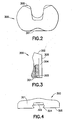
- FIG. 2 is a top plan view of the bearing shown in FIG. 1.
- FIG. 3 is aside elevational view, partly in section, of the bearing.
- FIG. 4 is a front elevational view of the bearing.
- FIG. 5 is a front elevational view of the control arm assembly.
- FIG. 6A is an exploded side elevational view of the control arm assembly.
- FIG. 6B is a side elevational view of the control arm assembly in its assembled condition.
- FIG. 7A is an exploded top plan view of the control arm assembly.
- FIG. 7B is a top plan view of the control arm assembly in its assembled condition.
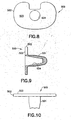
- FIG. 8 is a top plan view of the tibial component.
- FIG. 9 is a cross-sectional view of the tibial component taken along an anterior-posterior plane.
- FIG. 10 is a front elevational view of the tibial component.
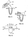
- FIG. 11 is a cross-sectional view of the bearing and the control arm being assembled with the tibial component.
- FIG. 12 is a cross-sectional view of the bearing and control arm fully assembled into the tibial component.
- FIG. 13 is a front elevational view of the assembled components of FIG. 12.
- a prosthetic knee device in accordance with the invention is identified by the numeral 100 and is shown in Fig. 1, at 162° of flexion. This is the maximum human passive flexion even in Asian cultures where deep squatting and sitting on the floor is common. During such flexion the tibia, and thus the tibial component 500, move forward relative to the femur and the bearing 300 moves backward on the tibial component as shown. Such motion is necessary to achieve flexion of this magnitude.
- the prosthetic knee device 100 comprises a femoral component 200, bearing 300, control arm 400 and a tibial component 500.
- the femoral and tibial components 200 and 500 respectively are identical to the femoral and tibial components in prior art LCS prosthetic knees.
- the bearing 300 is shown in FIGS 2-4. More particularly, the bearing 300 is similar to the earlier Flexglide bearing except the distance from its anterior surface 301 to its posterior surface 302 is somewhat less than the earlier design so as to reduce the potential for tissue impingement on deep flexion.
- the added width of the earlier bearing was an overreaction to the problem of spinout of the original rotating platform bearing.
- the original Flexglide bearing has the same plan form as the rotating platform bearing modified to improve resistance to spinout. Spinout is, however, not a problem with the Flexglide bearing and this increased width is not necessary.
- the bearing 300 also contains a stop recess 303 at an anterior and inferior extreme position on the bearing and a dovetail groove 304 that extends along the inferior surface 305 of the bearing from the anterior extreme to the posterior extreme. Anterior portions of the dovetail grove 304 align with the recess 303.
- the control arm assembly 400 is shown in FIGS 5-7. It is similar to that of U.S. Patent No. 5,702,466 except that the dovetail-shaped arm 401 is wider in order to provide additional stability of the control arm assembly 400. This stability is desirable since the cone 402 of this design is smaller than that of the original for the larger size knees.
- the control arm assembly 400 also contains a removable anterior stop 403 removably mounted to anterior portions of the control arm 401. More particularly, the control arm 401 is formed with an anterior notch 404 and two threaded apertures 405 extending posteriorly into the anterior notch 404. The stop 403 is configured to fit closely in the notch 404.
- the stop 403 is formed with two apertures 406 extending therethrough and disposed to align with the threaded apertures 405 in the notch 404 when the stop 403 is mounted in the notch 404.
- the stop 403 further includes two screws 407 rotatably trapped in the apertures 406 of the stop 403.
- the screws 407 are dimensioned for threaded engagement in the threaded apertures 405 of the control arm 401.
- the screws 407 can be used to removably mount the stop 403 to the anterior end of the control arm 400.
- the stop 403 is dimensioned to extend superiorly from anterior portions of the control arm 400 and is configured for engagement in the stop recess in the bearing 300.
- the tibial component includes a projection 501 configured for mounting in a recess prepared in the proximal end of the resected tibia.
- the tibial component 500 further includes a platform 502 with a substantially planar superior bearing surface 503 for bearing engagement with the inferior surface 305 of the bearing.
- a conical recess 504 extends through the platform 502 and into the projection 501. The conical recess is configured for rotatably receiving the cone 402 of the control arm assembly 400.
- the bearing 300 is assembled on to the control arm 400 by sliding the dovetail groove 304 onto the dovetail 401. The assembly is then inserted into the tibial component 500 in the usual fashion as shown in FIG. 11.
- the femoral component 200 In flexion the femoral component 200 will roll backward on the tibial component 500.
- the bearing 300 moves backward with the femoral component and thus will slide on the dovetailed connection backward on the control arm 400 as shown in FIG. 1.
- the femoral component 200 will roll forward on the tibial component 500.
- the bearing 300 will also move forward to the position shown in FIG. 12.
- the stop 403 prevents additional forward motion beyond this point. Such additional motion may result from a lax posterior cruciate ligament, or other reason. This reduces possible impingement with anterior knee tissues thereby reducing anterior knee pain. It also reduces anterior-posterior laxity of the knee.
- Revision surgery occasionally is necessary. As noted above, such revision surgery with prior art prostheses could require removal of a properly implanted femoral component merely to disassemble the prosthetic joint and to replace, for example, a defective bearing. With the subject invention, however, it is unnecessary to remove a properly implanted femoral component. Rather, the femoral component can remain in place and disassembly during revision surgery can be achieved easily merely by removing the stop 403. such removal can be achieved by unthreading the screws 407 which are accessible from anterior portions of the prosthetic component. Implantation of a new bearing can be achieved easily with the femoral component in place by retracting the joint sufficiently to allow the posterior lip of the bearing to clear the condyles of the femoral component.
Description
- A prosthetic knee joint is provided with a femoral component, a tibial component and a bearing between the femoral and tibial components. The bearing is capable of rotational movement on the tibial component and anterior-posterior sliding movement on the tibial component in response to flexion of the knee.
- U.S. Patent No. 5,702,466 shows a knee prosthesis with a tibial component that has a superior bearing surface. The prosthesis further includes a femoral component with an inferior articular bearing surface. A bearing is disposed between the tibial and femoral components and includes an inferior surface in rotating and sliding bearing engagement with the superior surface of the tibial component. The bearing further includes a superior surface in articular bearing contact with the inferior surface of the femoral component. Movement of the bearing on the tibial component is controlled by a control arm. More particularly, the bearing includes a groove that extends in an anterior-posterior direction in the inferior surface of the bearing. A control arm assembly is pivotally mounted to the tibial component and includes an arm that is slidably engaged in the groove of the bearing. Thus, the bearing and the control arm can rotate together on the superior surface of the tibial component. Additionally, the bearing can slide on the superior surface of the bearing and along the arm of the control arm assembly.
- The ability of the tibia to move forward relative to the femur is critical in the achievement of maximum passive flexion. If the tibia does not so move its posterior aspect will impinge sooner against the posterior aspect of the femur, thereby limiting flexion sooner. Where the posterior cruciate is not salvageable, or viable, the posterior stabilized knee device shown in U.S. Patent No. 6,491,726 produces such rearward motion. Where a viable posterior ligament is present one can use this ligament to generate this posterior motion of the femur on the tibia (rollback).
- A knee device that allows anterior-posterior motion of the femur on the tibia can allow maximum passive flexion even in the absence of a competent posterior cruciate ligament. As the leg is forced into maximum passive flexion the proximal tibia will be forced forward by pivoting on the impinging proximal, posterior tibial soft tissue if the prosthetic knee allows anterior motion of the proximal tibia. The absence of a competent posterior ligament, coupled with a device that permits anterior-posterior motion of the femur on the tibia, unfortunately, results in anterior-posterior instability of the knee. If this motion is unconstrained, except by the action of functioning ligaments, then the instability is likewise unconstrained and is undesirable.
- The position of the tibia during maximum passive flexion activities typically requires substantial axial rotation of the tibia relative to the femur. This rotation (approximately 25°) may be sufficient to produce placement of one of the posterior femoral condyles to be anterior to the posterior edge of its corresponding tibial condyle. That is, the femoral condyle may overhang the tibia on one side. Thus a knee replacement should also allow such rotation, but preferably without overhang. A device where the bearing can rotate on the tibial component is ideal for such a situation.
- The prosthesis shown in U.S. Patent No. 5,702,466 can be used for a knee device to exploit the ability of the posterior cruciate ligament to produce rollback and to provide anterior-posterior translation and axial rotation needed to obtain maximum passive flexion. Unfortunately there have been some problems experienced with this design in clinical use. Anterior knee pain, particularly on flexion, is one of these problems. This probably results from an incompetent posterior cruciate ligament producing anterior motion of the femur on the tibia rather than rollback. This anterior motion will produce impingement between the anterior aspect of the bearing and soft tissue structures of the knee. Such impingement can produce such pain. This incompetence is quite common and is the reason that anterior motion of the femur relative to the tibia is commonly observed with knee designs that allow such motion.
- A posterior stabilized knee, as, shown in U.S. Patent No. 6,475,241 or U.S. Patent No. 6,491,726 is preferred for those situations where a competent posterior ligament is not present. More particularly, the designs shown in U.S. Patent No. 6,475,241 and U.S. Patent No. 6,491,726 reliably produce needed rollback and provide needed axial bearing rotation. Further, these designs limit anterior-posterior instability to essentially normal limits. Where there is a competent posterior cruciate ligament a prosthetic device of the type shown in U.S. Patent No. 5,702,466 seems preferable since it allows the natural structures to provide such action rather than the mechanical structures of the posterior stabilized device.
- The problem however is that the identification of a viable cruciate ligament is not easily accomplished by many surgeons and a once competent ligament may become incompetent. Thus it is desirable to improve the performance of the prosthesis shown in U.S. Patent No. 5,702,466 in the presence of an incompetent posterior cruciate ligament.
- FIGS. 11-13 of U.S. Patent No. 5,702,466 show an embodiment where the arm of the control arm assembly is formed with a channel and where the bearing includes a shoulder engaged in the channel. The channel and the shoulder function to limit anterior movement of the bearing relative to the control arm and the tibial component and, hence, enhance stability in those situations where there is not a viable cruciate ligament or where the ligament becomes incompetent after implantation of the prosthesis. However, the interengageable channel and shoulder complicate implantation of the prosthesis and complicate removal of the prosthesis that may be required intraoperatively or during revision surgery.
- Surgery to implant the prosthetic device shown in FIGS. 11-13 of U.S. Patent No. 5,702,466 typically is completed by resecting the superior end of the tibia and the inferior end of the femur. The resected ends of the tibia and femur may be prepared further by forming cavities. The stem of the tibial component then is inserted into the cavity formed in the resected superior end of the tibia so that the platform of the tibial component is supported on the resected end of the tibia. The bearing then is assembled with the control arm and the cone that projects from the control arm is inserted into the conical recess in the tibial component. The femoral component then is mounted to the resected inferior surface of the femur. This sequence is required because the subassembly of the control arm and the bearing cannot be mounted easily into the conical recess of the tibial component once the femoral component has been mounted to the femur.
- Revision surgery occasionally is necessary. One possible reason for revision surgery would be to replace a defective bearing. In this situation, the femoral component is likely to be properly implanted and perfectly functional. The presence of the properly implanted femoral component significantly complicates the revision surgery, particularly during the implantation of the new bearing and control arm assembly. This implantation is particularly impeded for those prostheses where the control arm assembly is formed with a channel and where the bearing includes a shoulder to engage the channel as depicted in FIGS. 11-13 of U.S. Patent No. 5,702,466. Surgeons may try to retract the joint sufficiently so that the cone of the bearing/control arm subassembly can be inserted into the recess of the tibial component. However, such excessive retraction of the joint can stretch ligaments and complicate post-surgery recovery. In other instances, the surgeon may remove a properly implanted and perfectly functional femoral component so that the components of the prosthesis can be implanted during revision surgery in the same sequence employed during the initial surgery to implant the prosthesis. The femoral component often is secured in place by adhesive, bone tissue or some combination thereof. Hence, the removal of the properly implanted femoral component can damage the femur and contribute to post-surgery trauma for the patient.
- The presence of the properly implanted femoral component also can complicate the removal of the bearing and control arm assembly during revision surgery for those instances where the arm of the control arm assembly is formed with a channel and where the bearing includes a shoulder engaged in the channel. In particular, the control arm must be removed with the bearing. However, the cone of the control arm is trapped in the recess of the tibial component. Problems of removing the bearing during revision surgery are less severe than problems relating to the implantation of a new bearing during revision surgery. In particular, the previously implanted bearing can be broken by the surgeon and removed in pieces. This solution is not ideal, but may be acceptable during the bearing-removal phase of revision surgery. However, this option is not available to implant a new bearing because the preferred new bearing is of unitary construction.
- The subject invention was developed in view of these problems encountered during revision surgery. An object of the invention is to facilitate proper positioning of a bearing/control arm subassembly during revision surgery and particularly for those prosthetic joints that have structure for limiting anterior movement of the bearing relative to the control arm.
- The invention relates to a knee prosthesis according to claim 1 that has a femoral component having a superior surface for mounting to the resected inferior or distal end of a femur. The femoral component also has an inferior articular bearing surface with medial and lateral convex condyles. The knee joint prosthesis also includes a tibial component with an inferior face configured for mounting to the superior or proximal end of a resected tibia. The tibial component also has a superior bearing face. A bearing is disposed between the femoral and tibial components. The bearing includes an inferior bearing surface disposed in rotational and sliding bearing relationship with the superior surface of the tibial component. The bearing further includes a superior surface with concave condyles disposed in articular bearing engagement with the condyles of the femoral component. The concave superior surface of the bearing may be configured to provide surface contact with the condyles of the femoral component at full extension of the knee. However, the concave superior surface of the bearing is incongruent with the condyles of the femoral component during flexion, and achieves only line contact. The incongruency contributes to the generation of roll back during flexion, and hence contributes to anterior-posterior sliding movement of the bearing relative to the tibial component during flexion.
- The knee joint prosthesis further includes a control arm assembly. The control arm assembly is rotatably engaged with the femoral component and is slidably engaged with the inferior surface of the bearing. More particularly, the inferior surface of the bearing includes anterior-posterior groove that slidably engages the control arm. Anterior portions of the Control arm are formed with a stop that engages in a recess in the inferior surface of the bearing for limiting the amount of anterior sliding movement of the bearing on the tibial component and the control arm assembly. The engagement of the bearing with the stop on the control arm reduces or avoids possible impingement of the prosthesis with anterior knee tissues, thereby reducing anterior knee pain. The stop preferably is removably mounted to the control arm. More particularly, the stop preferably comprises attachment means for removable attachment of the stop to anterior portions of the control arm. The attachment means preferably is accessible from anterior portions of the assembled prosthesis.
- FIG. 1 is a side elevational view, partly in section, showing a knee joint prosthesis in accordance with the subject invention.
- FIG. 2 is a top plan view of the bearing shown in FIG. 1.
- FIG. 3 is aside elevational view, partly in section, of the bearing.
- FIG. 4 is a front elevational view of the bearing.
- FIG. 5 is a front elevational view of the control arm assembly.
- FIG. 6A is an exploded side elevational view of the control arm assembly.
- FIG. 6B is a side elevational view of the control arm assembly in its assembled condition.
- FIG. 7A is an exploded top plan view of the control arm assembly.
- FIG. 7B is a top plan view of the control arm assembly in its assembled condition.
- FIG. 8 is a top plan view of the tibial component.
- FIG. 9 is a cross-sectional view of the tibial component taken along an anterior-posterior plane.
- FIG. 10 is a front elevational view of the tibial component.
- FIG. 11 is a cross-sectional view of the bearing and the control arm being assembled with the tibial component.
- FIG. 12 is a cross-sectional view of the bearing and control arm fully assembled into the tibial component.
- FIG. 13 is a front elevational view of the assembled components of FIG. 12.
- A prosthetic knee device in accordance with the invention is identified by the numeral 100 and is shown in Fig. 1, at 162° of flexion. This is the maximum human passive flexion even in Asian cultures where deep squatting and sitting on the floor is common. During such flexion the tibia, and thus the
tibial component 500, move forward relative to the femur and thebearing 300 moves backward on the tibial component as shown. Such motion is necessary to achieve flexion of this magnitude. - The
prosthetic knee device 100 comprises afemoral component 200, bearing 300,control arm 400 and atibial component 500. The femoral andtibial components - The
bearing 300 is shown in FIGS 2-4. More particularly, thebearing 300 is similar to the earlier Flexglide bearing except the distance from itsanterior surface 301 to itsposterior surface 302 is somewhat less than the earlier design so as to reduce the potential for tissue impingement on deep flexion. The added width of the earlier bearing was an overreaction to the problem of spinout of the original rotating platform bearing. The original Flexglide bearing has the same plan form as the rotating platform bearing modified to improve resistance to spinout. Spinout is, however, not a problem with the Flexglide bearing and this increased width is not necessary. The bearing 300 also contains astop recess 303 at an anterior and inferior extreme position on the bearing and adovetail groove 304 that extends along theinferior surface 305 of the bearing from the anterior extreme to the posterior extreme. Anterior portions of thedovetail grove 304 align with therecess 303. - The
control arm assembly 400 is shown in FIGS 5-7. It is similar to that of U.S. Patent No. 5,702,466 except that the dovetail-shapedarm 401 is wider in order to provide additional stability of thecontrol arm assembly 400. This stability is desirable since thecone 402 of this design is smaller than that of the original for the larger size knees. Thecontrol arm assembly 400 also contains a removableanterior stop 403 removably mounted to anterior portions of thecontrol arm 401. More particularly, thecontrol arm 401 is formed with ananterior notch 404 and two threadedapertures 405 extending posteriorly into theanterior notch 404. Thestop 403 is configured to fit closely in thenotch 404. Thestop 403 is formed with twoapertures 406 extending therethrough and disposed to align with the threadedapertures 405 in thenotch 404 when thestop 403 is mounted in thenotch 404. Thestop 403 further includes twoscrews 407 rotatably trapped in theapertures 406 of thestop 403. Thescrews 407 are dimensioned for threaded engagement in the threadedapertures 405 of thecontrol arm 401. Thus, thescrews 407 can be used to removably mount thestop 403 to the anterior end of thecontrol arm 400. As shown in FIG. 6B, thestop 403 is dimensioned to extend superiorly from anterior portions of thecontrol arm 400 and is configured for engagement in the stop recess in thebearing 300. - The tibial component includes a
projection 501 configured for mounting in a recess prepared in the proximal end of the resected tibia. Thetibial component 500 further includes aplatform 502 with a substantially planarsuperior bearing surface 503 for bearing engagement with theinferior surface 305 of the bearing. Aconical recess 504 extends through theplatform 502 and into theprojection 501. The conical recess is configured for rotatably receiving thecone 402 of thecontrol arm assembly 400. - The
bearing 300 is assembled on to thecontrol arm 400 by sliding thedovetail groove 304 onto thedovetail 401. The assembly is then inserted into thetibial component 500 in the usual fashion as shown in FIG. 11. - In flexion the
femoral component 200 will roll backward on thetibial component 500. The bearing 300 moves backward with the femoral component and thus will slide on the dovetailed connection backward on thecontrol arm 400 as shown in FIG. 1. - During extension the
femoral component 200 will roll forward on thetibial component 500. Thus thebearing 300 will also move forward to the position shown in FIG. 12. Thestop 403 prevents additional forward motion beyond this point. Such additional motion may result from a lax posterior cruciate ligament, or other reason. This reduces possible impingement with anterior knee tissues thereby reducing anterior knee pain. It also reduces anterior-posterior laxity of the knee. - Revision surgery occasionally is necessary. As noted above, such revision surgery with prior art prostheses could require removal of a properly implanted femoral component merely to disassemble the prosthetic joint and to replace, for example, a defective bearing. With the subject invention, however, it is unnecessary to remove a properly implanted femoral component. Rather, the femoral component can remain in place and disassembly during revision surgery can be achieved easily merely by removing the
stop 403. such removal can be achieved by unthreading thescrews 407 which are accessible from anterior portions of the prosthetic component. Implantation of a new bearing can be achieved easily with the femoral component in place by retracting the joint sufficiently to allow the posterior lip of the bearing to clear the condyles of the femoral component.
Claims (9)
- A prosthesis comprising:a first component (500) having a first bearing surface (503);a second component (300) having a second bearing surface (305) disposed in sliding bearing engagement with the first bearing surface (503), the second bearing surface (305) including a groove (304) and a recess (303) formed at one end of said groove (304); anda control arm assembly (400) having a pivotal support (402) pivotally engaged with said first component (500), a control arm (401) slidably engaged in said groove (304) and a stop (403) removably mounted to one end of said control arm (401) and configured for releasable engagement in said recess (303) for limiting movement of said second component (300) relative to said first component (500).
- The prosthesis of claim 1, wherein the control, arm assembly (400) further includes attachments means (407) for removably attaching said stop (403) to said control arm (401), said attachment means (407) being accessible from said one end of said control arm (401).
- The prosthesis of claim 2, wherein the attachment means comprises at least one screw (407) passing through said stop (403) and threadedly engaging said control arm (401).
- The prosthesis of any of claims 1-3, wherein the prosthesis is a knee joint prosthesis, the first component (500) is a tibial component having a superior bearing surface (503), and wherein the second component (300) is a bearing having an inferior surface (305) in sliding bearing engagement with the superior bearing surface (503) of the tibial component (500).
- The prosthesis of any of daims 1 -4, wherein the control arm (401) indudes opposite anterior and posterior ends, the anterior end of the control arm including a notch (404), said stop (403) being engaged in said notch (404) at the anterior end of the control arm (401).
- The prosthesis of claim 4 or 5, wherein the tibial component (500) includes a recess (504) extending into the superior bearing surface (503) thereof, a cone (402) being pivotally mounted in the recess (504) and the control arm (401) being securely mounted to the cone (402).
- The prosthesis of any of claims 1-6, wherein the bearing (300) further includes a superior articular bearing surface, the prosthesis further comprising a femoral component (100) having an inferior articular bearing surface for articular bearing engagement with the superior articular bearing surface of the bearing (300).
- The prosthesis of any of claims 1-7, wherein the bearing (300) is formed from a non-metallic material and wherein said control arm (401) and said stop (403) are formed from a metallic material.
- The prosthesis of any of claims 1-8, wherein the groove (304) is a dovetail groove and wherein the control arm (401) is a dovetail control arm slidably engaged in said dovetail groove (304).
Applications Claiming Priority (2)
| Application Number | Priority Date | Filing Date | Title |
|---|---|---|---|
| US37160702P | 2002-04-10 | 2002-04-10 | |
| US371607P | 2002-04-10 |
Publications (3)
| Publication Number | Publication Date |
|---|---|
| EP1352620A2 EP1352620A2 (en) | 2003-10-15 |
| EP1352620A3 EP1352620A3 (en) | 2004-02-04 |
| EP1352620B1 true EP1352620B1 (en) | 2006-11-15 |
Family
ID=28454877
Family Applications (1)
| Application Number | Title | Priority Date | Filing Date |
|---|---|---|---|
| EP03007963A Expired - Lifetime EP1352620B1 (en) | 2002-04-10 | 2003-04-09 | Prosthetic knee with limited sliding movement of tibial bearing |
Country Status (6)
| Country | Link |
|---|---|
| US (1) | US7014660B2 (en) |
| EP (1) | EP1352620B1 (en) |
| JP (1) | JP4167922B2 (en) |
| AU (1) | AU2003203599B2 (en) |
| CA (1) | CA2424732C (en) |
| DE (1) | DE60309617T2 (en) |
Families Citing this family (11)
| Publication number | Priority date | Publication date | Assignee | Title |
|---|---|---|---|---|
| US7008454B2 (en) * | 2003-04-09 | 2006-03-07 | Biomedical Engineering Trust I | Prosthetic knee with removable stop pin for limiting anterior sliding movement of bearing |
| AU2006308865B2 (en) * | 2005-10-31 | 2012-10-25 | Depuy Products, Inc. | Modular fixed and mobile bearing prosthesis system |
| US20080091273A1 (en) | 2006-10-13 | 2008-04-17 | Hazebrouck Stephen A | Mobile/fixed prosthetic knee systems |
| US7740662B2 (en) | 2006-10-13 | 2010-06-22 | Depuy Products, Inc. | Mobile/fixed prosthetic knee systems |
| US20080114463A1 (en) * | 2006-10-13 | 2008-05-15 | Auger Daniel D | Mobile/fixed prosthetic knee systems |
| US20080091272A1 (en) * | 2006-10-13 | 2008-04-17 | Aram Luke J | Mobile/fixed prosthetic knee systems |
| US7998203B2 (en) * | 2008-06-06 | 2011-08-16 | Blum Michael F | Total knee prosthesis and method for total knee arthroplasty |
| US8617250B2 (en) * | 2011-06-17 | 2013-12-31 | Biomet Manufacturing, Llc | Revision knee tibial locking mechanism |
| GB2524668A (en) | 2012-09-10 | 2015-09-30 | Acumed Llc | Radial head prosthesis with floating articular member |
| GB2525044A (en) * | 2014-04-11 | 2015-10-14 | Biomet Uk Ltd | Prosthesis with fixed or mobile bearing |
| US9763792B2 (en) | 2015-10-01 | 2017-09-19 | Acumed Llc | Radial head prosthesis with rotate-to-lock interface |
Family Cites Families (38)
| Publication number | Priority date | Publication date | Assignee | Title |
|---|---|---|---|---|
| GB1507309A (en) | 1974-10-14 | 1978-04-12 | Atomic Energy Authority Uk | Prosthetic knee joints |
| GB1534263A (en) | 1974-11-18 | 1978-11-29 | Nat Res Dev | Endoprosthetic knee joint devices |
| US4001896A (en) * | 1975-06-09 | 1977-01-11 | Zimmer, U.S.A. Inc. | Prosthetic joint for total knee replacement |
| US4219893A (en) | 1977-09-01 | 1980-09-02 | United States Surgical Corporation | Prosthetic knee joint |
| US4007495A (en) | 1976-05-28 | 1977-02-15 | Frazier Calvin H | Patello-femoral prothesis |
| US4470158A (en) | 1978-03-10 | 1984-09-11 | Biomedical Engineering Corp. | Joint endoprosthesis |
| US4224697A (en) * | 1978-09-08 | 1980-09-30 | Hexcel Corporation | Constrained prosthetic knee |
| US4340978A (en) | 1979-07-02 | 1982-07-27 | Biomedical Engineering Corp. | New Jersey meniscal bearing knee replacement |
| US4309778A (en) | 1979-07-02 | 1982-01-12 | Biomedical Engineering Corp. | New Jersey meniscal bearing knee replacement |
| US4353136A (en) | 1980-11-05 | 1982-10-12 | Polyzoides Apostolos J | Endoprosthetic knee joint |
| EP0135319A3 (en) * | 1983-08-24 | 1985-07-24 | ARTHROPLASTY RESEARCH & DEVELOPMENT (PTY) LTD. | Knee prosthesis |
| US4640978A (en) * | 1984-09-13 | 1987-02-03 | Minnesota Mining And Manufacturing Company | Foam-sealed electrical devices and method and composition therefor |
| SE450460B (en) | 1984-11-28 | 1987-06-29 | Albrektsson Bjoern | DEVICE IN ARTIFICIAL MENISH FOR A KNEE JOINT PROTECTION |
| GB8432267D0 (en) | 1984-12-20 | 1985-01-30 | Thackray C F Ltd | Knee prosthesis |
| US4653136A (en) * | 1985-06-21 | 1987-03-31 | Denison James W | Wiper for rear view mirror |
| DE3529894A1 (en) | 1985-08-21 | 1987-03-05 | Orthoplant Endoprothetik | Knee-joint endoprosthesis |
| US4834081A (en) * | 1988-01-11 | 1989-05-30 | Boehringer Mannheim Corporation | Tool for removing modular joint prosthesis |
| US5194066A (en) * | 1988-01-11 | 1993-03-16 | Boehringer Mannheim Corporation | Modular joint prosthesis |
| GB2219942A (en) | 1988-06-22 | 1989-12-28 | John Polyzoides | Knee prosthesis |
| GB2223950B (en) | 1988-10-18 | 1992-06-17 | Univ London | Knee prosthesis |
| US5007933A (en) * | 1989-01-31 | 1991-04-16 | Osteonics Corp. | Modular knee prosthesis system |
| FR2663536B1 (en) | 1990-06-22 | 1998-02-13 | Implants Instr Ch Fab | TOTAL SLIDING TYPE KNEE PROSTHESIS. |
| US5370701A (en) | 1990-09-28 | 1994-12-06 | Arch Development Corporation | Rotating/sliding contrained prosthetic knee |
| ATE163354T1 (en) | 1990-11-14 | 1998-03-15 | Arch Dev Corp | IMPROVED KNEE PROSTHESIS WITH MOVABLE BEARING |
| US5395401A (en) | 1991-06-17 | 1995-03-07 | Bahler; Andre | Prosthetic device for a complex joint |
| DE9110504U1 (en) | 1991-08-24 | 1991-10-31 | Aesculap Ag, 7200 Tuttlingen, De | |
| DE4128171C1 (en) * | 1991-08-24 | 1993-04-01 | Aesculap Ag, 7200 Tuttlingen, De | |
| NZ243181A (en) * | 1992-04-23 | 1994-10-26 | Michael John Pappas | Prosthetic joint with guide means to limit articulation of a first element and bearing means to two degrees of freedom |
| FR2777452B1 (en) * | 1998-04-15 | 2000-12-15 | Aesculap Sa | KNEE PROSTHESIS |
| US6080195A (en) * | 1998-07-08 | 2000-06-27 | Johnson & Johnson Professional, Inc. | Rotatable and translatable joint prosthesis with posterior stabilization |
| CA2279660C (en) | 1998-08-05 | 2004-02-24 | Biomedical Engineering Trust I | Knee joint prosthesis with spinout prevention |
| US6319283B1 (en) * | 1999-07-02 | 2001-11-20 | Bristol-Myers Squibb Company | Tibial knee component with a mobile bearing |
| DE50007272D1 (en) * | 1999-09-24 | 2004-09-09 | Ct Pulse Orthopedics Ltd | Tibial part for a knee joint prosthesis and kit with such a tibial part |
| US6217618B1 (en) * | 1999-10-26 | 2001-04-17 | Bristol-Myers Squibb Company | Tibial knee component with a mobile bearing |
| FR2805454B1 (en) * | 2000-02-24 | 2003-01-10 | Aesculap Sa | KNEE PROSTHESIS WITH CAVITY IN THE TROCHLE |
| US6491726B2 (en) | 2000-03-08 | 2002-12-10 | Biomedical Engineering Trust I | Posterior stabilized prosthetic knee replacement with bearing translation and dislocation prevention features |
| US6475241B2 (en) * | 2000-03-13 | 2002-11-05 | Biomedical Engineering Trust I | Posterior stabilized knee replacement with bearing translation for knees with retained collateral ligaments |
| US6797005B2 (en) * | 2001-02-28 | 2004-09-28 | Biomedical Engineering Trust | Deep flexion posterior stabilized knee replacement with bearing translation |
-
2003
- 2003-04-07 CA CA002424732A patent/CA2424732C/en not_active Expired - Fee Related
- 2003-04-09 US US10/410,779 patent/US7014660B2/en not_active Expired - Lifetime
- 2003-04-09 EP EP03007963A patent/EP1352620B1/en not_active Expired - Lifetime
- 2003-04-09 AU AU2003203599A patent/AU2003203599B2/en not_active Ceased
- 2003-04-09 DE DE60309617T patent/DE60309617T2/en not_active Expired - Lifetime
- 2003-04-10 JP JP2003106218A patent/JP4167922B2/en not_active Expired - Fee Related
Also Published As
| Publication number | Publication date |
|---|---|
| AU2003203599B2 (en) | 2007-03-22 |
| US20030195634A1 (en) | 2003-10-16 |
| DE60309617D1 (en) | 2006-12-28 |
| CA2424732A1 (en) | 2003-10-10 |
| JP2004033747A (en) | 2004-02-05 |
| CA2424732C (en) | 2009-05-26 |
| EP1352620A3 (en) | 2004-02-04 |
| AU2003203599A1 (en) | 2003-11-06 |
| US7014660B2 (en) | 2006-03-21 |
| DE60309617T2 (en) | 2007-10-11 |
| JP4167922B2 (en) | 2008-10-22 |
| EP1352620A2 (en) | 2003-10-15 |
Similar Documents
| Publication | Publication Date | Title |
|---|---|---|
| EP1518520B1 (en) | Prosthetic knee with removable stop pin for limiting anterior sliding movement of bearing | |
| CA2279660C (en) | Knee joint prosthesis with spinout prevention | |
| US9763795B2 (en) | Motion facilitating tibial components for a knee prosthesis | |
| US6206926B1 (en) | Prosthetic knee joint with enhanced posterior stabilization and dislocation prevention features | |
| AU2011300819B2 (en) | Femoral prothesis with medialized patellar groove | |
| CN110731837B (en) | Ligament remains type shin bone tumour matched stack formula half knee joint prosthesis | |
| AU2002364107A1 (en) | Hinged joint system | |
| EP1352620B1 (en) | Prosthetic knee with limited sliding movement of tibial bearing | |
| EP0916321B1 (en) | Prosthetic knee joint with enhanced posterior stabilization and dislocation prevention features | |
| JP7198520B2 (en) | modular knee prosthesis | |
| US20120059485A1 (en) | Total Knee Trochlear System | |
| Yan et al. | Anterior dislocation of Insall Burstein II total knee arthroplasty secondary to polyethylene tibial post fracture: a case report | |
| WO1995023567A1 (en) | Modular ceramic knee prosthesis | |
| Rajgopal et al. | Cruciate-Retaining Total Knee Arthroplasty: Technique and Results | |
| Vince | Constrained Prostheses |
Legal Events
| Date | Code | Title | Description |
|---|---|---|---|
| PUAI | Public reference made under article 153(3) epc to a published international application that has entered the european phase |
Free format text: ORIGINAL CODE: 0009012 |
|
| AK | Designated contracting states |
Kind code of ref document: A2 Designated state(s): AT BE BG CH CY CZ DE DK EE ES FI FR GB GR HU IE IT LI LU MC NL PT RO SE SI SK TR |
|
| AX | Request for extension of the european patent |
Extension state: AL LT LV MK |
|
| PUAL | Search report despatched |
Free format text: ORIGINAL CODE: 0009013 |
|
| AK | Designated contracting states |
Kind code of ref document: A3 Designated state(s): AT BE BG CH CY CZ DE DK EE ES FI FR GB GR HU IE IT LI LU MC NL PT RO SE SI SK TR |
|
| AX | Request for extension of the european patent |
Extension state: AL LT LV MK |
|
| 17P | Request for examination filed |
Effective date: 20040311 |
|
| AKX | Designation fees paid |
Designated state(s): CH DE FR GB IE IT LI |
|
| GRAP | Despatch of communication of intention to grant a patent |
Free format text: ORIGINAL CODE: EPIDOSNIGR1 |
|
| GRAS | Grant fee paid |
Free format text: ORIGINAL CODE: EPIDOSNIGR3 |
|
| GRAA | (expected) grant |
Free format text: ORIGINAL CODE: 0009210 |
|
| AK | Designated contracting states |
Kind code of ref document: B1 Designated state(s): CH DE FR GB IE IT LI |
|
| REG | Reference to a national code |
Ref country code: GB Ref legal event code: FG4D |
|
| REG | Reference to a national code |
Ref country code: CH Ref legal event code: EP |
|
| REF | Corresponds to: |
Ref document number: 60309617 Country of ref document: DE Date of ref document: 20061228 Kind code of ref document: P |
|
| REG | Reference to a national code |
Ref country code: IE Ref legal event code: FG4D |
|
| ET | Fr: translation filed | ||
| PLBE | No opposition filed within time limit |
Free format text: ORIGINAL CODE: 0009261 |
|
| STAA | Information on the status of an ep patent application or granted ep patent |
Free format text: STATUS: NO OPPOSITION FILED WITHIN TIME LIMIT |
|
| 26N | No opposition filed |
Effective date: 20070817 |
|
| REG | Reference to a national code |
Ref country code: CH Ref legal event code: NV Representative=s name: PATENTANWAELTE SCHAAD, BALASS, MENZL & PARTNER AG |
|
| PGFP | Annual fee paid to national office [announced via postgrant information from national office to epo] |
Ref country code: DE Payment date: 20120425 Year of fee payment: 10 Ref country code: IE Payment date: 20120424 Year of fee payment: 10 Ref country code: CH Payment date: 20120426 Year of fee payment: 10 |
|
| PGFP | Annual fee paid to national office [announced via postgrant information from national office to epo] |
Ref country code: FR Payment date: 20120523 Year of fee payment: 10 Ref country code: GB Payment date: 20120425 Year of fee payment: 10 |
|
| PGFP | Annual fee paid to national office [announced via postgrant information from national office to epo] |
Ref country code: IT Payment date: 20120428 Year of fee payment: 10 |
|
| REG | Reference to a national code |
Ref country code: CH Ref legal event code: PL |
|
| GBPC | Gb: european patent ceased through non-payment of renewal fee |
Effective date: 20130409 |
|
| REG | Reference to a national code |
Ref country code: IE Ref legal event code: MM4A |
|
| PG25 | Lapsed in a contracting state [announced via postgrant information from national office to epo] |
Ref country code: DE Free format text: LAPSE BECAUSE OF NON-PAYMENT OF DUE FEES Effective date: 20131101 Ref country code: CH Free format text: LAPSE BECAUSE OF NON-PAYMENT OF DUE FEES Effective date: 20130430 Ref country code: LI Free format text: LAPSE BECAUSE OF NON-PAYMENT OF DUE FEES Effective date: 20130430 Ref country code: GB Free format text: LAPSE BECAUSE OF NON-PAYMENT OF DUE FEES Effective date: 20130409 |
|
| REG | Reference to a national code |
Ref country code: FR Ref legal event code: ST Effective date: 20131231 |
|
| REG | Reference to a national code |
Ref country code: DE Ref legal event code: R119 Ref document number: 60309617 Country of ref document: DE Effective date: 20131101 |
|
| PG25 | Lapsed in a contracting state [announced via postgrant information from national office to epo] |
Ref country code: FR Free format text: LAPSE BECAUSE OF NON-PAYMENT OF DUE FEES Effective date: 20130430 Ref country code: IT Free format text: LAPSE BECAUSE OF NON-PAYMENT OF DUE FEES Effective date: 20130409 |
|
| PG25 | Lapsed in a contracting state [announced via postgrant information from national office to epo] |
Ref country code: IE Free format text: LAPSE BECAUSE OF NON-PAYMENT OF DUE FEES Effective date: 20130409 |