EP1351523A2 - System for enhancing the quality of an image - Google Patents
System for enhancing the quality of an image Download PDFInfo
- Publication number
- EP1351523A2 EP1351523A2 EP03251980A EP03251980A EP1351523A2 EP 1351523 A2 EP1351523 A2 EP 1351523A2 EP 03251980 A EP03251980 A EP 03251980A EP 03251980 A EP03251980 A EP 03251980A EP 1351523 A2 EP1351523 A2 EP 1351523A2
- Authority
- EP
- European Patent Office
- Prior art keywords
- image
- light
- screen
- focus device
- variable
- Prior art date
- Legal status (The legal status is an assumption and is not a legal conclusion. Google has not performed a legal analysis and makes no representation as to the accuracy of the status listed.)
- Withdrawn
Links
Images


Classifications
-
- H—ELECTRICITY
- H04—ELECTRIC COMMUNICATION TECHNIQUE
- H04N—PICTORIAL COMMUNICATION, e.g. TELEVISION
- H04N5/00—Details of television systems
- H04N5/74—Projection arrangements for image reproduction, e.g. using eidophor
-
- H—ELECTRICITY
- H04—ELECTRIC COMMUNICATION TECHNIQUE
- H04N—PICTORIAL COMMUNICATION, e.g. TELEVISION
- H04N9/00—Details of colour television systems
- H04N9/12—Picture reproducers
- H04N9/31—Projection devices for colour picture display, e.g. using electronic spatial light modulators [ESLM]
- H04N9/3102—Projection devices for colour picture display, e.g. using electronic spatial light modulators [ESLM] using two-dimensional electronic spatial light modulators
- H04N9/3111—Projection devices for colour picture display, e.g. using electronic spatial light modulators [ESLM] using two-dimensional electronic spatial light modulators for displaying the colours sequentially, e.g. by using sequentially activated light sources
- H04N9/3114—Projection devices for colour picture display, e.g. using electronic spatial light modulators [ESLM] using two-dimensional electronic spatial light modulators for displaying the colours sequentially, e.g. by using sequentially activated light sources by using a sequential colour filter producing one colour at a time
-
- H—ELECTRICITY
- H04—ELECTRIC COMMUNICATION TECHNIQUE
- H04N—PICTORIAL COMMUNICATION, e.g. TELEVISION
- H04N9/00—Details of colour television systems
- H04N9/12—Picture reproducers
- H04N9/31—Projection devices for colour picture display, e.g. using electronic spatial light modulators [ESLM]
- H04N9/3141—Constructional details thereof
- H04N9/317—Convergence or focusing systems
-
- H—ELECTRICITY
- H04—ELECTRIC COMMUNICATION TECHNIQUE
- H04N—PICTORIAL COMMUNICATION, e.g. TELEVISION
- H04N5/00—Details of television systems
- H04N5/74—Projection arrangements for image reproduction, e.g. using eidophor
- H04N5/7416—Projection arrangements for image reproduction, e.g. using eidophor involving the use of a spatial light modulator, e.g. a light valve, controlled by a video signal
Definitions
- display systems and display methods have been used over the years to generate images. For example, both front and rear projection systems are used today to display images.
- Such display systems may employ image devices, such as cathode ray tubes (CRTs), liquid crystal displays (LCDs), or electrically-addressed emissive displays, e.g. plasma displays.
- CTRs cathode ray tubes
- LCDs liquid crystal displays
- emissive displays e.g. plasma displays.
- the display systems further may incorporate a passive display screen or an active display screen.
- each display system depends on numerous factors, including, but not limited to, image quality, image resolution, image brightness, display size, cost, weight, design, etc.
- a consumer may choose a display system based on any one factor, or any combination of these factors. For example, the level of shading or half-toning may be important to a consumer when the display system is primarily used to display graphical or photographic images. Edge definition and contrast also may be important. A consumer may want a display system having both high quality shading and high quality edge definition. However, until now, the cost of display systems that attempt to provide both high quality half-toning and high quality edge definition has been prohibitive.
- a system for enhancing the quality of an image on a screen typically includes an illumination source configured to produce light and direct such light along an optical path, and a variable focus device disposed in the optical path and configured to sequentially alter incident light to enhance the quality of the image on the screen.
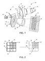
- Fig. 1 illustrates, at 10, a display system that is configured to generate and display images on a screen.
- Display system 10 may be a rear projection display system, a front projection display system or some other suitable display system.
- display system 10 includes a projector 11 and a screen 16, wherein the projector is adapted to project image information onto the screen.
- an image is projected via a projector onto the screen such that the image is visible by a viewer situated on the opposite side of the screen from the projector.
- the projector and screen are integrated in a single unit.
- the viewer typically is located on the same side of the screen as the projector.
- the projector may be spaced-apart and separate from the screen.
- Projector 11 typically includes a light source or illumination source 12 configured to direct image information along an optical path 14 toward screen 16.
- the image information is used to produce an image 18 on screen 16.
- image includes both still images and video images.
- Illumination source 12 may be any suitable light source adapted to transmit image information to screen 16.
- illumination source 12 may be a single beam light source such as a mercury lamp, a multiple beam light source, multiple colored lights, etc.
- Illumination source 12 may produce white light and/or colored light.
- light from illumination source 12 is directed through optics 20, such as a lens, onto a color light modulator 22.
- Color light modulator 22 thus may separate light provided by illumination source 12 into a plurality of colors.
- color light modulator 22 includes a color wheel 23.
- Color wheel 23 has three color regions, a red region 24, a green region 28, and a blue region 26.
- the color wheel may be configured such that the color regions sequentially filter light from the illumination source. It should be noted that other types of color light modulators may be used, including wheels having different sizes of color regions, number of regions, and/or colors of regions.
- the combination of illumination source 12 and color light modulator 22 functions to produce colored light, and is effectively a type of color light source that may be implemented in display system 10.
- illumination source 12 itself may generate colored light.
- illumination source 12 may include a plurality of colored lights. More specifically, an array of red, blue and green colored lights may be used as an alternative to the mercury lamp and color wheel described above. It further should be appreciated that other devices may be used to produce colored light, and are within the scope of the invention.
- Spatial light modulator 30 may be any suitable light-modulating device, such as a micromirror array (e.g., a digital micromirror device (DMD) or a digital light processor). Spatial light modulator 30 is adapted to produce modulated light that is directed onto screen 16.
- a micromirror array e.g., a digital micromirror device (DMD) or a digital light processor.
- Spatial light modulator 30 is adapted to produce modulated light that is directed onto screen 16.
- Modulated light from spatial light modulator 30 may be further focused and positioned prior to impinging on screen 16.
- colored light, directed to screen 16 is passed through projection optics 34.
- Projection optics 34 may include one or more projection lenses.
- projection optics 34 is adapted to focus, size and position the colored light on screen 16 to generate an image 18.
- projection optics 34 may function as a variable focus device.
- variable focus device 36 disposed within the optical path.
- the variable focus device may be integrated within projection optics 34 and/or separated from projection optics 34, as shown in Fig. 1.
- variable focus device 36 enhances the quality of the image by changing the effective or apparent resolution of the image on the screen to a viewer.
- variable focus device 36 is configured to vary the diameter of the light beam as it is projected onto screen 16. By varying a dimension or dimensions of the light beam, a corresponding image and/or image portion may be enlarged or contracted, effectively changing the image and/or image portion between a focused and an unfocused/defocused state.
- variable focus device may be configured to temporarily enlarge individual image portions, causing the image portions to overlap, to generate a homogenous image. Stated otherwise, variable focus device 36 alters the projected light by periodically changing the focus or focal point of the light beam.
- Variable focus device 36 may be any suitable device having differing optical characteristics.
- variable focus device 36 may be a time-varying lens adapted to intermittently change the focal length of the light beam.
- Variable focus device 36 thus may be a diverging lens, a converging lens, or other suitable focusing or defocusing lens configured to periodically interrupt the optical path.
- variable focus device 36 may be a reflective and/or a refractive lens.
- an exemplary variable focus device 36 is shown as a focus wheel 37, similar to color wheel 23, described above.
- focus wheel 37 may include multiple lens regions of differing optical characteristics.
- focus wheel 37 includes two regions, a first lens region 38 having a first optical characteristic and a second lens region 40 having a second optical characteristic.
- Each of the depicted lens regions is radially disposed about focus wheel 37 and is configured such that incident light sequentially impinges each lens region as the focus wheel rotates over time. It should be noted that the position and number of lens regions may vary, and thus, focus wheel 37 may have one, two, three, four or more lens regions.
- each lens region may have a specific curvature.
- the curvature of the lens may cause the incident light beam to either converge or diverge.
- the resulting image or portion of the image may be sequentially focused and defocused.
- the spatial light modulator includes a plurality of mirrors.
- Each mirror typically individually directs or reflects a portion of light toward the display screen, and thereby, generates a portion of the image to be displayed on the screen.
- each mirror may be slightly spaced from its neighboring mirrors.
- the mirrors generate a slightly discontinuous image, formed of multiple, discrete image portions.
- the image portions may be visible to a viewer. In other words, a viewer may be able to see a division or break in the image where portions of the image are reflected from different mirrors. On the screen, the image thus may appear to have lines defining a series of discrete image portions.
- Fig. 2 shows a fragment of screen 16 with a representation of an image 18 as displayed both before and after implementation of a variable focus device as described herein.
- Image 18 may be generated, for example, via a spatial light modulator having a plurality of mirrors. As indicated previously, each mirror may produce a portion of the image. For illustrative purposes, portions of the image are generally indicated at 50. Each image portion 50 is adjacent other image portions so as to cooperatively produce image 18.
- Lines 52 represent the effect of reflection of discrete image portions from multiple mirrors. As shown to the left in Fig. 2, before implementation of the variable focus device described herein, lines 52 are visible to a viewer. Although illustrated as solid lines, lines 52 are typically dark spaces that outline each image portion 50, thereby creating a "screen door effect.” In other words, image 18 may appear tiled.
- variable focus device 36 may reduce or eliminate the visibility of lines 52.
- each image portion 50 is successively focused and defocused, blending the image portions together so as to create a more homogenous image.
- the image portions are rapidly expanded and contracted as the reflected light is passed through different lens regions of variable focus device 36.
- lines 52 may become less prominent to a viewer.
- image 18 typically remain clear to a viewer.
- the image may be focused and defocused so rapidly that a viewer does not perceive the change in the focus of the image.
- the image portions may be selectively focused and defocused to maximize blending in some parts of the image and minimize blending in other parts of the image for example, parts that contain predominantly text.
- the spatial light modulator may be adapted to modulate the light into a plurality of discrete light beams.
- Each modulated light beam may be configured to produce a light spot on the screen of a first size.
- the variable focus device may be configured to selectively vary the size of the light spot on the screen between the first size and a second size. These light spots may have different optical characteristics or visual characteristics. Such a configuration may be used to enhance the apparent resolution of the image to a viewer.
- Variable focus device 36 further may be used to control intensity.
- intensity may be controlled by turning the micromirrors on and off. Turning on and off of the micromirrors, however, may result in a shimmering effect that may be observable by a viewer.
- Use of a variable focus device provides an alternate method of controlling the intensity of the image.
- a variable focus device may be configured to selectively enlarge some frames of an image. These enlarged images may be lower resolution images employing fewer than all of the micromirrors. Nevertheless, with proper enlargement of the image frames, such image frames may appear as low intensity, low resolution image frames. Thus, by interleaving the low intensity, low resolution image frames with higher intensity, higher resolution image frames (e.g., using the variable focus device), the shimmering effect may be eliminated.
- Figs. 3 and 4 illustrate alternative embodiments of display system 10.
- light 60 in Figs. 3 and 4 is produced via an illumination source or light source 62.
- Light source 62 may direct light 60 through color light modulator 64 to produce colored light 68.
- light source 62 may be configured to produce colored light independent of the use of color light modulator 64.
- any suitable color light source 66 may be used to produce colored light 68.
- Colored light 68 may be further directed onto spatial light modulator 70, which produces modulated colored light 72. Modulated colored light 72 may then pass through projection optics 74, through variable focus device 76, and onto screen 78.
- variable focus device 76 may be integrated within projection optics 74.
- variable focus device 76 may be independent of the projection optics, and placed prior to and/or after projection optics 74 in the light path. Regardless of the position of variable focus device 76, light that passes through device 76 may be modified to produce alternatively focused and defocused images or portions of images on screen 78.
- Display system 10 may include a controller 86 configured to manage the generation of an image.
- controller 86 may manage color light source 66, spatial light modulator 70, and/or variable focus device 76.
- controller 86 is adapted to receive color image information from color light modulator 64 and control operation of spatial light modulator 70 based on the color information to generate an image.
- controller 86 may control the speed and position of a color wheel.
- controller 86 may directly control color light source 66.
- Controller 86 further may control variable focus device 76 in combination with spatial light modulator 70 to modulate the image and/or portions of the image.
- controller 86 may control variable focus device 76, such that the effect of a variable focus device is realized on the screen. Controller 86 may rapidly alter variable focus device 76 between differing focus characteristics, thereby causing the image or portions of the image to shift between a focused and defocused state.
- controller 86 may control variable focus device 76 such that the displayed image or portions of the image shift rapidly between a focused and defocused state.
- variable focus device 76 may be independently managed by a discrete controller (not shown).
- controller 86 may be configured to independently actuate each micromirror to control the color and intensity of the corresponding image portion on the screen. Additionally, controller 86 may manage the variable focus device, as described above, so that select portions of the image are focused and defocused. Such control may enhance quality of the image, by blending of colors, while maintaining sharp edges and light/dark contrasts within the image.
- variable focus device 76 in display system 10 where variable focus device 76 is positioned after spatial light modulator 70 and prior to projection optics 74.
- the variable focus device may include one or more reflective lens, such as mirrors, and/or one or more refractive lens, which are configured to bend or diverge incident light as it passes therethrough.
- light 68 may be produced via a color light source 66.
- Light 68 may be directed toward a spatial light modulator 70, and the resulting modulated light 72 further directed onto variable focus device 76, through projection optics 74, and onto screen 78.
- Fig. 5 illustrates a variable focus device 76 in the form of deformable or variable-curvature mirror array 90.
- Variable-curvature mirror includes any mirror or surface that may be varied over time to change the light reflection. The reflected light generates an image or portion of an image that alters between a focused and unfocused state.
- the spatial light modulation itself may be formed from an array of deformable mirrors, thereby integrating the variable focus device with the micromirror array of the special light modulator.
- variable-curvature mirror may be used, including but not limited to, deformable mirrors, adaptive optical elements, bimorph mirrors, etc.
- a variable-curvature mirror may include a plurality of electrically addressable actuators that controllably deform the surface of the mirror. The actuators may be individually actuated such that portions of the image may be selectively focused and defocused.
- variable-curvature mirror 91 may be varied between a flat state, indicated at 92, and a curved state, indicated at 94.
- Variable-curvature mirror portion 91 may include a reflective surface 96 that is capable of alternating between a flat configuration and at least one curved configuration.
- Surface 96 is typically coated with a reflecting coating and may be coupled to a layer of a piezo-electric material or piezo element 98.
- a voltage may be applied to piezo element 98, causing the piezo element to expand/contract laterally. Such expansion/contraction results in the entire structure bending, thereby changing the surface curvature of variable-curvature mirror portion 91.
- variable-curvature mirror array 90 may have a plurality of individually-controlled piezo elements and multiple mirror portions 91. By applying different voltages to different piezo elements, the shape of the mirror may be controlled.
- variable-curvature mirror array 90 In operation, incident light impinges surface 96 of variable-curvature mirror array 90. As described above, the curvature of surface 96 may be controlled by piezo element 98 within variable-curvature mirror array 90. At times, surface 96 may be substantially flat. At other times, surface 96 may be curved to varying degrees. The curvature affects the light as it impinges upon the surface, thereby altering the focus of the image on the screen. Thus, depending on the configuration of variable-curvature mirror array 90, an image or a portion of an image is generated on screen 78 in either a focused or unfocused state.
- variable focus 76 device may utilize bimorph mirror elements.
- Each bimorph mirror element may be formed via a multilayer structure including a layer of piezoelectric material and a layer of passive material. An exposed surface of this material may be coated with a reflective material. Upon activation (via a voltage) of the piezo electric material, the curvature of the mirror element changes, for example, from a flat to a curved state.
- Figs. 7-10 show alternative embodiments for variable focus device 76.
- Figs. 7-10 illustrate a plurality of focus wheels or spinning lenses that may be implemented within a display system.
- Each depicted focus wheel may function as a diverging lens.
- Each focus wheel thus may be configured to vary the focus of the incident light over time as it impinges the screen.
- the depicted focus wheels include lens regions which differ in curvature and which are successively positioned within the optical path as the wheels rotate or spin.
- Fig. 7 illustrates a focus wheel 100 adapted to be disposed within the optical path.
- Focus wheel 100 includes a lens region 102 that extends arcuately along a portion of the lens. Although illustrated as extending half-way around the lens, it should be noted that lens region 102 may extend any distance.
- lens region 102 is a concave region that is configured to cause divergence of the incident light. Specifically, incident light 104 diverges as it passes through lens region 102, as indicated at 105. Depending on the configuration of the lens region, the lens region may cause the light beam to laterally diverge, vertically diverge, or both.
- focus wheel 100 may rotate about axis 107 as indicated by arrow 106.
- the light diverges vertically, thus affecting the focus of the light on the screen.
- a second focus wheel 110 shown in Fig. 9, substantially identical to focus wheel 100, may be used alone, in combination with, or in sequence with, focus wheel 100 with a second lens region 112 configured to cause horizontal divergence of an incident light beam 104.
- the two wheels may be positioned, such that in combination, a light beam may be vertically and horizontally diverged.
- Fig. 10 illustrates another embodiment for variable focus device 76.
- another focus wheel 116 is illustrated having a plurality of lens regions 118 and 120.
- the two lens regions 118 and 120 may have differing curvatures. Such curvature may affect the degree of divergence or convergence of the light as the light is passed through the different lens regions. It should be noted that any number of lens regions may be employed.
- lens region 118 may have substantially little or no curvature, while lens region 120 is sharply curved.
- focus wheel 116 rotates, light is sequentially passed through the different lens regions 118 and 120.
- the rotation of focus wheel 116 it is possible to selectively focus and defocus the image or portions of the image.
- the light spot size on the screen is enlarged. Such enlargement may improve images or portions of images that require gradual shading and/or blending.
- the lens region that causes a minimal degree of divergence is within the optical path, the light spot size remains smaller. The smaller light spot enables edges, such as text, to be sharply focused, thus making such edges distinct and clear.
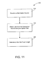
- Method 200 typically includes, at 202, providing an illumination source configured to generate a light beam.
- the method further includes, at 204, directing the light beam from the illumination source along an optical path and onto a screen.
- the focal length of the light beam is selectively altered to intermittently change at least a portion of the image on the screen.
- the focal point or focus of a corresponding image portion on the screen is altered.
- focused and defocused images may be interleaved on the screen.
- each image portion may be brought into and out of focus.
- a temporarily defocused image portion is configured to overlap with an adjacent image portion and causes the overall image to appear blended. Such blending improves the quality of the image to a viewer.
Landscapes
- Engineering & Computer Science (AREA)
- Multimedia (AREA)
- Signal Processing (AREA)
- Projection Apparatus (AREA)
- Optical Elements Other Than Lenses (AREA)
- Microscoopes, Condenser (AREA)
- Endoscopes (AREA)
Abstract
Description
Claims (10)
- An image projection system (10) configured to enhance quality of an image (18) on a screen (16, 78), the system (10) comprising: an illumination source (12) configured to produce light (60, 68) and direct light (60, 68) along an optical path (14); and a time-varying focus device (36, 76) disposed in the optical path (14) and configured to periodically alter incident light (72) to enhance quality of the image (18) on the screen (16, 78).
- The image projection system (10) of claim 1, wherein the time-varying focus device (36, 76) is configured to periodically diverge incident light (72).
- The image projection system (10) of claim 1, wherein the time-varying focus device (36, 76) is configured to periodically converge incident light (72).
- The image projection system (10) of claim 1, wherein the time-varying focus device (36, 76) is a variable-curvature mirror (90).
- The image projection system (10) of claim 4, wherein the variable-curvature mirror (90) employs a piezo element (98) to alter curvature of the mirror 90.
- The image projection system (10) of claim 1, wherein the time-varying focus device (36, 76) is a wheel (37, 100, 116) having regions of differing optical characteristic (38, 40, 102, 118, 120).
- The image projection system (10) of claim 1, wherein the time-varying focus device (36, 76) is configured to selectively alter incident light (72) to change intensity of the image (18) on the screen (16, 78).
- A display system (10) configured to enhance the quality of an image (18) on a screen (16, 78), the system (10) comprising: an illumination source (12) configured to direct light (60, 68) along an optical path (14); a spatial light modulator (30) adapted to modulate the light (60, 68) into a plurality of discrete light beams (72), each light beam (72) configured to project a light spot on the screen of a first size; and a variable focus device (36, 76) disposed in the optical path (14) and configured to vary size of light spots on the screen (16, 78) between the first size and a second size such that a corresponding image portion (50) on the screen (16, 78) rapidly alternates between a focused state and a defocused state to enhance the appearance of the image (18).
- A method for enhancing the quality of an image (18) on a screen (16, 78), the method comprising: providing an illumination source (12) configured to generate a light beam (60, 68); directing the light beam (60, 68) from the illumination source (12) along an optical path (14) to produce image frames (50) on a screen (16, 78), wherein each image frame (50) has a focal length; and selectively altering the focal lengths of the image frames (50) to produce interleaved image frames having differing focal lengths on the screen (16, 78).
- A display device (11) configured to display an image (18) on a screen (16, 78), the system comprising: illumination means (12) for producing a light beam (60, 68); light modulating means (30) for directing the light beam (60, 68) onto a screen (16, 78) to form an image (18); and variable focus means (36) for successively varying size of the light beam (60, 68) such that the image (18) on the screen (16, 78) alternates between a focused and an unfocused state.
Applications Claiming Priority (2)
| Application Number | Priority Date | Filing Date | Title |
|---|---|---|---|
| US114645 | 2002-04-01 | ||
| US10/114,645 US6729734B2 (en) | 2002-04-01 | 2002-04-01 | System for enhancing the quality of an image |
Publications (2)
| Publication Number | Publication Date |
|---|---|
| EP1351523A2 true EP1351523A2 (en) | 2003-10-08 |
| EP1351523A3 EP1351523A3 (en) | 2005-07-27 |
Family
ID=28041050
Family Applications (1)
| Application Number | Title | Priority Date | Filing Date |
|---|---|---|---|
| EP03251980A Withdrawn EP1351523A3 (en) | 2002-04-01 | 2003-03-28 | System for enhancing the quality of an image |
Country Status (6)
| Country | Link |
|---|---|
| US (2) | US6729734B2 (en) |
| EP (1) | EP1351523A3 (en) |
| JP (1) | JP3942549B2 (en) |
| KR (1) | KR20030079714A (en) |
| CA (1) | CA2420793A1 (en) |
| TW (1) | TWI258630B (en) |
Families Citing this family (49)
| Publication number | Priority date | Publication date | Assignee | Title |
|---|---|---|---|---|
| KR100533611B1 (en) * | 2000-06-16 | 2005-12-05 | 샤프 가부시키가이샤 | Projection type image display device |
| US20040155856A1 (en) * | 2002-01-16 | 2004-08-12 | Peter Richards | Sequential color illumination in display systems employing light modulators |
| TW594371B (en) * | 2003-01-29 | 2004-06-21 | Benq Corp | Image projection system with an invisible-light reflector for heat dissipation |
| JP3909595B2 (en) * | 2003-04-23 | 2007-04-25 | セイコーエプソン株式会社 | Display device and dimming method thereof |
| US6974232B1 (en) * | 2003-10-14 | 2005-12-13 | Brian Edward Richardson | Compact lighting system with improved light transmission and color filters |
| US7044606B2 (en) * | 2004-03-29 | 2006-05-16 | Hewlett-Packard Development Company, L.P. | Projection of pixelized color images |
| US7188957B2 (en) * | 2004-10-20 | 2007-03-13 | Hewlett-Packard Development Company, L.P. | Projection systems and methods for both color and monochromatic displays |
| KR100644644B1 (en) | 2004-10-28 | 2006-11-10 | 삼성전자주식회사 | Illumination system without laser spots and 1-panel projection system |
| US7213926B2 (en) * | 2004-11-12 | 2007-05-08 | Hewlett-Packard Development Company, L.P. | Image projection system and method |
| US20060187417A1 (en) * | 2005-02-21 | 2006-08-24 | Seiko Epson Corporation | Projector |
| US20060187222A1 (en) * | 2005-02-23 | 2006-08-24 | Childers Winthrop D | Changing states of elements |
| JP4281729B2 (en) * | 2005-02-28 | 2009-06-17 | セイコーエプソン株式会社 | projector |
| KR100617587B1 (en) * | 2005-04-07 | 2006-09-01 | 삼성전기주식회사 | Tilting device |
| US20060250583A1 (en) * | 2005-05-05 | 2006-11-09 | Andrew Huibers | Multi-mode projectors with spatial light modulators |
| US7661828B2 (en) * | 2005-06-10 | 2010-02-16 | Hewlett-Packard Development Company, L.P. | Adjusting light intensity |
| US20070052695A1 (en) * | 2005-09-07 | 2007-03-08 | Barnes Ted W | Generating and displaying spatially offset sub-frames |
| US7611250B2 (en) * | 2005-10-27 | 2009-11-03 | Chunghwa Picture Tubes, Ltd. | Projector |
| US20090290132A1 (en) * | 2005-10-27 | 2009-11-26 | Fergal Shevlin | Image Projection Display System |
| US7499206B1 (en) * | 2005-12-09 | 2009-03-03 | Brian Edward Richardson | TIR light valve |
| JP4584160B2 (en) * | 2006-03-01 | 2010-11-17 | Necディスプレイソリューションズ株式会社 | Projection display |
| US20070247715A1 (en) * | 2006-04-21 | 2007-10-25 | Melvin Francis | Projection illumination systems lenses with diffractive optical elements |
| US20070290962A1 (en) * | 2006-06-19 | 2007-12-20 | Texas Instruments Incorporated | Method and system for displaying an image |
| US9661287B2 (en) | 2006-08-19 | 2017-05-23 | David J. Baker | Wave based light beam delivery system |
| US9001028B2 (en) | 2006-08-19 | 2015-04-07 | David James Baker | Projector pen |
| US20080143969A1 (en) * | 2006-12-15 | 2008-06-19 | Richard Aufranc | Dynamic superposition system and method for multi-projection display |
| TWI336205B (en) * | 2007-07-13 | 2011-01-11 | Optoma Corp | Playback control methods and systems |
| US8508447B2 (en) * | 2007-11-19 | 2013-08-13 | Microsoft Corporation | Display device and pixel therefor |
| US8107056B1 (en) * | 2008-09-17 | 2012-01-31 | University Of Central Florida Research Foundation, Inc. | Hybrid optical distance sensor |
| US8272770B2 (en) | 2009-01-02 | 2012-09-25 | Rambus International Ltd. | TIR switched flat panel display |
| US8152352B2 (en) * | 2009-01-02 | 2012-04-10 | Rambus International Ltd. | Optic system for light guide with controlled output |
| US20100315836A1 (en) * | 2009-06-11 | 2010-12-16 | Brian Edward Richardson | Flat panel optical display system with highly controlled output |
| US8152318B2 (en) * | 2009-06-11 | 2012-04-10 | Rambus International Ltd. | Optical system for a light emitting diode with collection, conduction, phosphor directing, and output means |
| US8297818B2 (en) * | 2009-06-11 | 2012-10-30 | Rambus International Ltd. | Optical system with reflectors and light pipes |
| US9380273B1 (en) * | 2009-10-02 | 2016-06-28 | Rockwell Collins, Inc. | Multiple aperture video image enhancement system |
| CN102713421A (en) * | 2009-11-18 | 2012-10-03 | 拉姆伯斯国际公司 | Internal collecting reflector optics for LEDs |
| TW201300702A (en) | 2011-05-13 | 2013-01-01 | Rambus Inc | Lighting assembly |
| US8733978B2 (en) * | 2011-06-17 | 2014-05-27 | Sutter Instrument Company | Optical filter system and method |
| KR102190030B1 (en) | 2012-12-03 | 2020-12-14 | 삼성전자주식회사 | Plasma generating apparatus |
| TWI465772B (en) * | 2013-03-27 | 2014-12-21 | Delta Electronics Inc | Stereoscopic display illuminator and stereoscopic display device |
| US9291340B2 (en) | 2013-10-23 | 2016-03-22 | Rambus Delaware Llc | Lighting assembly having n-fold rotational symmetry |
| KR101589726B1 (en) | 2014-02-21 | 2016-01-28 | 주식회사 에이치엠알텍 | Harmful gas collecting device for surface treatment system |
| US9632404B2 (en) * | 2015-03-18 | 2017-04-25 | Disney Enterprises, Inc. | Projection system for enhancing and modifying the appearance of a projection surface |
| US10409031B2 (en) | 2015-11-18 | 2019-09-10 | Maxell, Ltd. | Image projection apparatus |
| JP6679950B2 (en) * | 2016-01-26 | 2020-04-15 | セイコーエプソン株式会社 | Projector and projector control method |
| US10162252B2 (en) * | 2016-07-28 | 2018-12-25 | Panasonic Intellectual Property Management Co., Ltd. | Phosphor disc, phosphor wheel, light source device, projection display apparatus, and manufacturing method of phosphor disc |
| US11284053B2 (en) | 2019-03-29 | 2022-03-22 | Razmik Ghazaryan | Head-mounted display and projection screen |
| US10466489B1 (en) | 2019-03-29 | 2019-11-05 | Razmik Ghazaryan | Methods and apparatus for a variable-resolution screen |
| US10554940B1 (en) | 2019-03-29 | 2020-02-04 | Razmik Ghazaryan | Method and apparatus for a variable-resolution screen |
| WO2026036284A1 (en) * | 2024-08-14 | 2026-02-19 | Jade Bird Display (shanghai) Limited | System and method of a high definition micro-led display |
Family Cites Families (27)
| Publication number | Priority date | Publication date | Assignee | Title |
|---|---|---|---|---|
| US3603722A (en) * | 1970-06-26 | 1971-09-07 | Nasa | Color television system |
| JPS56117484A (en) * | 1980-02-20 | 1981-09-14 | Matsushita Electric Ind Co Ltd | Television picture receiver of projection type |
| US4759605A (en) | 1985-07-15 | 1988-07-26 | Raychem Corporation | Apparatus for coupling light between an optical fiber and a light element |
| US6243057B1 (en) | 1990-11-16 | 2001-06-05 | Digital Projection Limited | Deformable mirror device driving circuit and method |
| JPH04352139A (en) * | 1991-05-30 | 1992-12-07 | Matsushita Electric Ind Co Ltd | Liquid crystal projection type display |
| US5274492A (en) | 1992-07-02 | 1993-12-28 | Mahmoud Razzaghi | Light spot size and shape control for laser projector |
| GB9217392D0 (en) * | 1992-08-15 | 1992-09-30 | Light & Sound Design Ltd | Colour image protection apparatus |
| JP3395280B2 (en) * | 1993-09-21 | 2003-04-07 | 株式会社ニコン | Projection exposure apparatus and method |
| JPH07294866A (en) * | 1994-04-27 | 1995-11-10 | Mitsubishi Electric Corp | Projector device |
| JPH08251520A (en) | 1995-03-08 | 1996-09-27 | Nikon Corp | Video projector |
| US5777589A (en) | 1995-04-26 | 1998-07-07 | Texas Instruments Incorporated | Color display system with spatial light modulator(s) having color-to-color variations in data sequencing |
| US5758955A (en) * | 1995-07-11 | 1998-06-02 | High End Systems, Inc. | Lighting system with variable shaped beam |
| EP0817157A3 (en) | 1996-06-28 | 1998-08-12 | Texas Instruments Incorporated | Improvements in or relating to image display system |
| US6293680B1 (en) | 1997-09-10 | 2001-09-25 | Thermotrex Corporation | Electromagnetically controlled deformable mirror |
| US5934778A (en) | 1998-03-10 | 1999-08-10 | Nec Corporation | Optical system for liquid crystal projector |
| US5993009A (en) * | 1998-03-16 | 1999-11-30 | Optical Gaging Products, Inc. | Multiple magnification contour projector |
| US6100862A (en) | 1998-04-20 | 2000-08-08 | Dimensional Media Associates, Inc. | Multi-planar volumetric display system and method of operation |
| US6183092B1 (en) | 1998-05-01 | 2001-02-06 | Diane Troyer | Laser projection apparatus with liquid-crystal light valves and scanning reading beam |
| US6231190B1 (en) | 1998-06-22 | 2001-05-15 | Texas Instruments Incorporated | Color correction filter for displays |
| US6220730B1 (en) * | 1998-07-01 | 2001-04-24 | Light & Sound Design, Ltd. | Illumination obscurement device |
| US6264333B1 (en) * | 1998-07-24 | 2001-07-24 | Asahi Kogaku Kogyo Kabushiki Kaisha | Reflection type projector |
| US6304316B1 (en) | 1998-10-22 | 2001-10-16 | Anvik Corporation | Microlithography system for high-resolution large-area patterning on curved surfaces |
| US6280035B1 (en) | 1998-10-23 | 2001-08-28 | Duke University | Lens design to eliminate color fringing |
| KR100305322B1 (en) | 1998-11-07 | 2001-11-30 | 구본준, 론 위라하디락사 | Liquid crystal display device with repair line |
| JP3069860B1 (en) * | 1999-05-24 | 2000-07-24 | 日本アイ・ビー・エム株式会社 | Single-panel color projector |
| US6416185B1 (en) * | 1999-06-30 | 2002-07-09 | Intel Corporation | Managing differential focus in projection displays |
| US6267478B1 (en) * | 2000-06-06 | 2001-07-31 | Yu-Shen Chen | Pattern-changing structure for a projection light system |
-
2002
- 2002-04-01 US US10/114,645 patent/US6729734B2/en not_active Expired - Lifetime
-
2003
- 2003-01-28 TW TW092101865A patent/TWI258630B/en not_active IP Right Cessation
- 2003-02-27 CA CA002420793A patent/CA2420793A1/en not_active Abandoned
- 2003-03-12 JP JP2003065989A patent/JP3942549B2/en not_active Expired - Lifetime
- 2003-03-28 EP EP03251980A patent/EP1351523A3/en not_active Withdrawn
- 2003-03-31 KR KR10-2003-0019864A patent/KR20030079714A/en not_active Ceased
- 2003-10-31 US US10/699,435 patent/US6832839B2/en not_active Expired - Lifetime
Also Published As
| Publication number | Publication date |
|---|---|
| JP3942549B2 (en) | 2007-07-11 |
| US20040090604A1 (en) | 2004-05-13 |
| US6832839B2 (en) | 2004-12-21 |
| JP2003302700A (en) | 2003-10-24 |
| EP1351523A3 (en) | 2005-07-27 |
| US6729734B2 (en) | 2004-05-04 |
| KR20030079714A (en) | 2003-10-10 |
| TW200305052A (en) | 2003-10-16 |
| US20030184718A1 (en) | 2003-10-02 |
| CA2420793A1 (en) | 2003-10-01 |
| TWI258630B (en) | 2006-07-21 |
Similar Documents
| Publication | Publication Date | Title |
|---|---|---|
| US6832839B2 (en) | System for enhancing the quality of an image | |
| US8059340B2 (en) | Method and system for reducing speckle by vibrating a line generating element | |
| JPWO1998029773A1 (en) | Image display device | |
| US7573633B2 (en) | Increase gray scales of projection system by reflecting light from mirror elements with non-uniform intensity distribution | |
| US7330298B2 (en) | Optical system and method for increasing image resolution and/or dithering in projection applications | |
| JP2010271443A (en) | Projector and image display method | |
| JP4736350B2 (en) | Projector and display device | |
| US7636190B2 (en) | Method of projecting an image from a reflective light valve | |
| KR200315584Y1 (en) | Optical system of projecting apparatus | |
| HK1056283A (en) | System for enhancing the quality of an image | |
| US20060176362A1 (en) | Optical system and method for increasing image resolution and/or dithering in printing applications | |
| JP2003149599A (en) | Projection display device | |
| JP4655514B2 (en) | projector | |
| JP4003606B2 (en) | Illumination optical device and projector using the same | |
| KR100208679B1 (en) | Actuated mirror array optical projection system and a projection method using the same | |
| KR100208675B1 (en) | Actuated Mirror Array Optics | |
| KR100208662B1 (en) | Projection type image display device and projection method using the same | |
| KR100209954B1 (en) | Actuated mirror array optical system and projection method using the same | |
| KR100251113B1 (en) | Optical system of ama | |
| KR19980040064A (en) | Optical Projection System and Light Projection Method Using The Same | |
| KR19980085794A (en) | Deformable Mirror Device Projector and Projection Method Using The Same | |
| KR100251112B1 (en) | Actuated mirror array optics and projection method using the same | |
| KR19990012813A (en) | Optical System of Projection Image Display Using AM | |
| KR19990034630A (en) | Projection type image display device | |
| JP2001242393A (en) | Panel device and projection device using the same |
Legal Events
| Date | Code | Title | Description |
|---|---|---|---|
| PUAI | Public reference made under article 153(3) epc to a published international application that has entered the european phase |
Free format text: ORIGINAL CODE: 0009012 |
|
| AK | Designated contracting states |
Kind code of ref document: A2 Designated state(s): AT BE BG CH CY CZ DE DK EE ES FI FR GB GR HU IE IT LI LU MC NL PT SE SI SK TR |
|
| AX | Request for extension of the european patent |
Extension state: AL LT LV MK RO |
|
| PUAL | Search report despatched |
Free format text: ORIGINAL CODE: 0009013 |
|
| AK | Designated contracting states |
Kind code of ref document: A3 Designated state(s): AT BE BG CH CY CZ DE DK EE ES FI FR GB GR HU IE IT LI LU MC NL PT SE SI SK TR |
|
| AX | Request for extension of the european patent |
Extension state: AL LT LV MK RO |
|
| RIC1 | Information provided on ipc code assigned before grant |
Ipc: 7H 04N 5/74 B Ipc: 7H 04N 9/31 A |
|
| 17P | Request for examination filed |
Effective date: 20060111 |
|
| AKX | Designation fees paid |
Designated state(s): DE FR GB NL |
|
| 17Q | First examination report despatched |
Effective date: 20080319 |
|
| STAA | Information on the status of an ep patent application or granted ep patent |
Free format text: STATUS: THE APPLICATION IS DEEMED TO BE WITHDRAWN |
|
| 18D | Application deemed to be withdrawn |
Effective date: 20080730 |
|
| REG | Reference to a national code |
Ref country code: HK Ref legal event code: WD Ref document number: 1056283 Country of ref document: HK |