EP1351201A2 - Gaming control system and method of assembling the same - Google Patents
Gaming control system and method of assembling the same Download PDFInfo
- Publication number
- EP1351201A2 EP1351201A2 EP03007407A EP03007407A EP1351201A2 EP 1351201 A2 EP1351201 A2 EP 1351201A2 EP 03007407 A EP03007407 A EP 03007407A EP 03007407 A EP03007407 A EP 03007407A EP 1351201 A2 EP1351201 A2 EP 1351201A2
- Authority
- EP
- European Patent Office
- Prior art keywords
- connector
- gaming control
- control board
- power
- interface board
- Prior art date
- Legal status (The legal status is an assumption and is not a legal conclusion. Google has not performed a legal analysis and makes no representation as to the accuracy of the status listed.)
- Withdrawn
Links
Images




Classifications
-
- G—PHYSICS
- G07—CHECKING-DEVICES
- G07F—COIN-FREED OR LIKE APPARATUS
- G07F17/00—Coin-freed apparatus for hiring articles; Coin-freed facilities or services
- G07F17/32—Coin-freed apparatus for hiring articles; Coin-freed facilities or services for games, toys, sports, or amusements
- G07F17/3202—Hardware aspects of a gaming system, e.g. components, construction, architecture thereof
-
- G—PHYSICS
- G07—CHECKING-DEVICES
- G07F—COIN-FREED OR LIKE APPARATUS
- G07F17/00—Coin-freed apparatus for hiring articles; Coin-freed facilities or services
- G07F17/32—Coin-freed apparatus for hiring articles; Coin-freed facilities or services for games, toys, sports, or amusements
-
- G—PHYSICS
- G07—CHECKING-DEVICES
- G07F—COIN-FREED OR LIKE APPARATUS
- G07F17/00—Coin-freed apparatus for hiring articles; Coin-freed facilities or services
- G07F17/32—Coin-freed apparatus for hiring articles; Coin-freed facilities or services for games, toys, sports, or amusements
- G07F17/3202—Hardware aspects of a gaming system, e.g. components, construction, architecture thereof
- G07F17/3216—Construction aspects of a gaming system, e.g. housing, seats, ergonomic aspects
-
- Y—GENERAL TAGGING OF NEW TECHNOLOGICAL DEVELOPMENTS; GENERAL TAGGING OF CROSS-SECTIONAL TECHNOLOGIES SPANNING OVER SEVERAL SECTIONS OF THE IPC; TECHNICAL SUBJECTS COVERED BY FORMER USPC CROSS-REFERENCE ART COLLECTIONS [XRACs] AND DIGESTS
- Y10—TECHNICAL SUBJECTS COVERED BY FORMER USPC
- Y10T—TECHNICAL SUBJECTS COVERED BY FORMER US CLASSIFICATION
- Y10T29/00—Metal working
- Y10T29/49—Method of mechanical manufacture
- Y10T29/49002—Electrical device making
- Y10T29/49117—Conductor or circuit manufacturing
- Y10T29/49124—On flat or curved insulated base, e.g., printed circuit, etc.
- Y10T29/4913—Assembling to base an electrical component, e.g., capacitor, etc.
-
- Y—GENERAL TAGGING OF NEW TECHNOLOGICAL DEVELOPMENTS; GENERAL TAGGING OF CROSS-SECTIONAL TECHNOLOGIES SPANNING OVER SEVERAL SECTIONS OF THE IPC; TECHNICAL SUBJECTS COVERED BY FORMER USPC CROSS-REFERENCE ART COLLECTIONS [XRACs] AND DIGESTS
- Y10—TECHNICAL SUBJECTS COVERED BY FORMER USPC
- Y10T—TECHNICAL SUBJECTS COVERED BY FORMER US CLASSIFICATION
- Y10T29/00—Metal working
- Y10T29/49—Method of mechanical manufacture
- Y10T29/49716—Converting
Definitions
- the present invention relates generally to gaming machines, and, more particularly, to a circuit board having low-power circuitry and high-power circuitry for controlling the operation of a gaming machine.
- the electronics of a gaming machine typically include a backplane which provides connectors for connection to various devices of the gaming machine, a logic circuit board which includes a central processing unit, memory, and other logic circuitry, and an I/O circuit board which includes communications and power interfaces to devices of the gaming machine.
- the logic circuit board and the I/O circuit board are "piggybacked" to the backplane via separate connectors, and are thus disposed parallel to one another.
- the communications interfaces of the I/O circuit board may also include logic circuitry, so the connector connecting the I/O circuit board to the backplane may carry both low-power digital signals and high-power analog signals. The mixing of digital and high-power signals may cause undesirable crosstalk.
- the digital and high-power signals from the I/O circuit board are connected to pins on the connector such that a digital signal and a high-power signal are not presented to consecutive pins of the connector.
- This arrangement imposes design challenges as it is often convenient and intuitive to provide digital and high power signals to consecutive pins on the connector.
- the piggybacking of the logic circuit board and the I/O circuit board may create an undesired electromagnetic coupling between the two boards, which can adversely affect signal integrity as the high-current traces create EM fields that radiate away from the I/O circuit board.
- the backplane is connected to the logic circuit board and the I/O circuit board in a perpendicular relationship, further potentially causing undesired electromagnetic coupling between the backplane and the logic circuit board and the I/O circuit board.
- a gaming control system for use in a gaming machine includes low-power, logic components and high-power components disposed on a gaming control board.
- the logic components include a CPU which is adapted to execute instructions for randomly selecting a plurality of game outcomes in response to wagers inputted by a player.
- the high-power components interface the gaming control board with high-power devices of the gaming machine. Examples of high-power devices include lamps, a payoff mechanism, a currency validator, and a power supply.
- the gaming control board includes a first connector that carries low-power signals between the logic components on the gaming control board and an interface board coupled thereto, and a second connector that carries high-power signals between the high-power components on the gaming control board and the high-power devices of the gaming machine.
- the high-power components on the gaming control board are located near the second connector for optimal EMI suppression.
- the interface board and the gaming control board are positioned in a generally coplanar arrangement with respect to each other to reduce undesired electromagnetic coupling between the gaming control board and the interface board.
- a housing encloses the gaming control board to shield against the undesired effects of electromagnetic interference.
- FIG. 1 illustrates a block diagram of selected electronic circuitry and devices of a typical gaming machine 10.
- the electronic circuitry of the gaming machine 10 generally includes a central processing unit (CPU) 12, digital logic and system memory circuitry 14, communications interface components 16, and power interface components 18.
- the communications interface components 16 are coupled to peripheral devices such as a host 20, a network 22, and a money/credit detector 24 (such as a currency validator).
- the power interface components 18 are coupled to peripheral devices such as a payoff mechanism 26 and lamps 28.
- a power supply 30 supplies power to the electronic components of the gaming machine 10.
- the payoff mechanism 26 may be a coin/token hopper, a coupon/ticket/bill dispenser, or a media reader, for example.
- the gaming machine 10 includes numerous other devices which are not shown in FIG. 1, such as any combination of game pushbuttons, coin optos, sensors, a video display, a touchscreen, a reel, a printer, and audio devices, for example.
- a backplane 32 interfaces the devices of the gaming machine including the host 20, the network 22, the money/credit detector 24, the payoff mechanism 26, and the lamps 28 with the communications interface components 16 and the power interface components 18.
- the devices are connected to the backplane 32 via one or more wiring harnesses, and the backplane 32 is connected to the communications interface components 16 and the power interface components 18 via one or more connectors.
- FIG. 2 shows the electronic circuitry disposed on a single gaming control board 40 according to the present invention.
- the gaming control board includes low-power components and high-power components.
- the low-power components include a CPU 42, a system memory 44, digital logic components 46, and communications interface components 48.
- the high-power components include power interface components 50.
- a first connector 52 and a second connector 54 are disposed on the gaming control board 40.
- the first connector 52 is adapted to mate with a first game interface board connector 56 on a game interface board 60.
- the second connector 54 is adapted to mate with a second game interface board connector 58 on the game interface board 60.
- the first connector 52 and the first game interface board connector 56 are complements of each other.
- the first connector 52 may be a male-type connector and the first game interface board connector 56 may be a female-type connector, or vice versa.
- the second connector 54 and the second game interface board connector 58 are complements of each other.
- the second connector 54 may be a female-type connector and the second game interface board connector 58 may be a male-type connector, or vice versa.
- the first connector 52 is coupled to the digital logic components 46 which carry low-power signals on line 62 to the first game interface board connector 56 when the first connector 52 and the first game interface board connector 56 are connected together.
- the low-power signals on line 62 include low-power I/O signals such as digital or TTL-level signals or low-power analog signals.
- the second connector 54 is coupled to the power interface components 50 which carry high-power signals on line 64 to the second game interface board connector 58 when the second connector 54 and the second game interface board connector 58 are connected together.
- the high-power signals on line 64 include power-supply signals from a power supply 66 and driver signals which carry electrical power to high-power devices of the gaming machine 10 such as lamps.
- the first game interface board connector 56 and the second game interface board connector 58 are disposed on the game interface board 60 to engage and mate with the first connector 52 and second connector 54 of the gaming control board 40 when the gaming control board 40 and the game interface board 60 are connected together.
- the connectors 52, 54, 56, 58 are zero-insertion force (ZIF) connectors, and may be locked together with a locking actuator, for example.
- ZIF zero-insertion force
- a force must be applied to mate connectors 52, 54 to connectors 56, 58, respectively.
- the first connector 52 and the first game interface board connector 56 are of a 160-pin, D-sub type
- the second connector 54 and the second game interface board connector 58 are of a 37-pin, D-sub type.
- the low-power I/O signals on line 62 are coupled to the game interface board 60 through the first connector 52 and the first game interface board connector 56. Because of the low-current carrying capacity of these signals, the pins on the connectors 52, 56 may be close together, with relatively little electrical isolation between pins. As a result, the connectors 52, 56 may include substantially more pins than the connectors 54, 58.
- the high-power signals on line 64 demand greater electrical isolation to prevent electromagnetic coupling between adjacent signals, and therefore, the connectors 54, 58 are not as densely packed with pins as the connectors 52, 56.
- the ratio of the number of pins on the connectors 52, 56 to the number of pins on the connectors 54, 58 is at least three-to-one, and the spacing between pins of the connectors 54, 58 is about 0.120 inches, and the spacing between pins of the connectors 52, 56 is about 0.040 inches.
- the gaming control board 40 may also include one or more other connectors, such as, for example, a serial port connector, a parallel port connector, a USB connector, a video display connector, or a CompactFlash card connector.
- a serial port connector such as, for example, a serial port connector, a parallel port connector, a USB connector, a video display connector, or a CompactFlash card connector.
- the game interface board 60 is connected to peripheral devices of the gaming machine 10 such as, for example, a host 68, a network 70, a money/credit detector 72, a payoff mechanism 110, and lamps 76.
- peripheral devices of the gaming machine 10 such as, for example, a host 68, a network 70, a money/credit detector 72, a payoff mechanism 110, and lamps 76.
- the gaming machine 10 may include other devices besides those shown in FIG. 2.
- the payoff mechanism 110 may be a coin/token hopper, a coupon/ticket/bill dispenser, and a media reader, for example.
- system memory 44 includes a separate read-only memory (ROM) and battery-backed or nonvolatile random-access memory (RAM).
- ROM read-only memory
- RAM nonvolatile random-access memory
- system memory 44 may be implemented on any of several alternate types of memory structures or may be implemented on a single memory structure.
- the digital logic components 46 may include any combination of the following: a video controller, a host controller, a digital signal processor (DSP), an application-specific integrated circuit (ASIC), a field-programmable gate array (FPGA), or any other suitable transistor-transistor logic (TTL) components.
- DSP digital signal processor
- ASIC application-specific integrated circuit
- FPGA field-programmable gate array
- TTL transistor-transistor logic
- the CPU 42 and memory 44 are also digital logic components.
- the communications interface components 48 may include a Universal Asynchronous Receiver-Transmitter (UART) integrated circuit and/or a Universal Serial Bus (USB) controller for providing a communications interface with other devices or systems.
- UART Universal Asynchronous Receiver-Transmitter
- USB Universal Serial Bus
- the power interface components 50 may include driver circuitry, such as lamp driver circuitry for driving the lamps of the gaming machine 10, motor driver circuitry for driving various motors in the gaming machine 10, and power supply components for converting voltages from the power supply 30 to appropriate levels. These power interface components 50 are preferably disposed proximate the second connector 54 to reduce the effects of undesired electromagnetic coupling generated by the high current levels.
- the coplanar arrangement of the gaming control board 40 and the game interface board 60 also advantageously reduces the effects of noise that might be coupled from the high-current carrying traces and components.
- the gaming control board 40 is mounted on standoffs and enclosed in a housing 78.
- the housing 78 protects the gaming control board 40 from the effects of electromagnetic interference (EMI) and is made of an EMI-shielded material, such as metal or metal particle-coated plastic.
- EMI electromagnetic interference
- the gaming machine 10 operates as follows.
- the money/credit detector 72 signals the CPU 42 when a player has inserted money or played a number of credits.
- the money may be provided by coins, bills, tickets, coupons, cards, etc.
- the CPU 42 operates to execute a game program that causes the display 80 to display simulated symbol-bearing reels.
- the player may select a number of pay lines to play, an amount to wager, and start game play via a touch screen 90 or push-buttons 92, causing the CPU 42 to set the reels in motion, randomly select a game outcome or a plurality of game outcomes, and then stop the reels to display symbols corresponding to the pre-selected game outcome.
- one of the basic game outcomes triggers a bonus feature.
- the system memory 44 stores control software, operational instructions and data associated with the gaming machine 10.
- a payoff mechanism 100 is operable in response to instructions from the CPU 42 to award a payoff to the player in response to certain winning outcomes that might occur in the basic game or the bonus feature.
- the payoff may be provided in the form of coins, bills, tickets, coupons, cards, etc.
- the payoff amounts are determined by one or more pay tables stored in the system memory 44.
- FIG. 3 illustrates an isometric, cut-away view of the housing 78 enclosing the gaming control board 40 in accordance with one embodiment of the present invention.
- the housing 78 includes a first latch engaging slot 110 and a second latch engaging slot 112 along a front panel 114 of the housing 78.
- the housing 78 further includes a door 124, which is preferably made of the same material (such as metal, for example) as the housing 78.
- the front panel 114 of the housing 78 also includes a first door hook aperture 116a and second door hook aperture 116b, a switch engaging aperture 118, a switch aperture 122, and mounting guide slots 126.
- the front panel 114 also includes apertures dimensioned to accept therethrough the first connector 52 and the second connector 54 of the gaming control board 40.
- the housing 78 includes a rear interchangeable panel 130 which includes connector slots dimensioned to receive respective interface connectors on the gaming control board 40.
- the rear interchangeable panel 130 includes a 15-pin D-sub connector slot 132, a 9-pin D-sub connector slot 134, a USB connector slot 136, and a CompactFlash card slot 138.
- a CompactFlash card housing 140 accepts a CompactFlash card inserted through the CompactFlash card slot 138.
- the CompactFlash card includes software such as, for example, game code, game graphics, sound operating system code, sound data, and so forth. It is understood that fewer, additional, or other connector slots may be formed in the rear interchangeable panel 130.
- the rear interchangeable panel 130 is removable to facilitate insertion and removal of the gaming control board 40 for repairs, upgrades, and the like.
- the rear interchangeable panel 130 may be replaced with another rear interchangeable panel having a different configuration of connector slots in order to accommodate a gaming control board having a different arrangement of interface connectors.
- the rear interchangeable panel 130 is not removable.
- one or more panels of the housing 78 may include a pattern of air holes 142 to facilitate the circulation of air across the gaming control board 40.
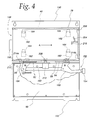
- FIG. 4 illustrates a gaming control board assembly 148, which comprises the housing 78 and the gaming control board 40, in a pre-attachment position with respect to the game interface board 60 according to one aspect of the present invention.
- the game interface board 60 (a portion of which has been partially removed to expose the docking mechanism 152) is mounted to a mounting plate 150 which is secured to the interior of the gaming machine 10 or may form an interior wall of the gaming machine 10.
- a docking mechanism 152 includes an operating lever 154 pivotally mounted to the mounting plate 150, a first latching member 156 rotatably secured to the operating lever 154, and a second latching member 158 rotatably secured to the operating lever 154.
- a connecting member 160 is coupled between the first latching member 156 and second latching member 158.
- the operating lever 154 shown in FIGS. 4, 6, and 7 is dimensioned to extend beyond the mounting plate 150. In another embodiment, the operating lever 154 may be dimensioned to extend no further than the edge of the mounting plate 150.
- the housing 78 includes at least one locating guide 162 disposed on the panel facing the mounting plate 150.
- the locating guide 162 is an aperture formed in desired locations on the panel of the housing 78 facing the mounting plate 150.
- the mounting plate 150 includes at least one pre-attachment registration mechanism 164.
- the pre-attachment registration mechanism 164 is a shear-formed mounting hook formed along the surface of the mounting plate 150. The locating guide 162 and pre-attachment registration mechanism 164 permit registration of the gaming control board assembly 148 and the game interface board 60 so that both are in the proper alignment before they are urged together.
- the locating guide 162 may be a shear-formed mounting hook and the pre-attachment registration mechanism 164 may be an aperture, or the locating guide 162 or pre-attachment registration mechanism 164 may be a rail, groove, channel, or the like formed so as to align the gaming control board assembly 148 and the game interface board 60 in the pre-attachment position.
- a positioning guide 166 attached to the mounting plate 150 is bent slightly outwards from the plane of the mounting plate 150 to help guide the gaming control board assembly 148 into the pre-attachment position.
- a user positions the gaming control board assembly 148 against the positioning guide 166 and "slides” the gaming control board assembly 148 along the positioning guide 166 until the locating guides 162 and pre-attachment registration mechanism 164 are aligned with each other.
- Other positioning tabs may be formed to further assist the user in registering the gaming control board assembly 148 with the game interface board 60.
- FIG. 5 illustrates a side view of the gaming control board assembly 148 in a docked position relative to the game interface board 60.
- the second connector 54 engages the second game interface board connector 58 as shown, and the first connector 52 also engages the first game interface board connector 56.
- the pre-attachment registration mechanism 164 holds the housing 78 against the mounting plate 150 and prevents the housing 78 from being pulled away from the mounting plate 150.
- the door 124 of the housing 78 includes a security tab 168 (also shown in FIG. 8) to prevent unauthorized access to the CompactFlash card slot 138.
- the security tab 168 covers the CompactFlash card slot 138, preventing CompactFlash cards from being inserted into or removed from the CompactFlash card housing 140.
- the door 124 does not include the security tab 168.
- other security tabs may be formed on the door 124 to prevent access to certain I/O ports via the rear interchangeable panel 130 of the housing 78.
- FIGS. 7 and 8 The operation of the operating lever 154 between an undocked position and a docked position will be discussed next with reference to FIGS. 7 and 8. For ease of illustration, some of the details shown in FIGS. 4-6 are not shown in FIGS. 7 and 8. For example, it is understood that the housing 78 encloses the gaming control board 40.
- the operating lever 154 In FIG. 6, the operating lever 154 is in the undocked position.
- the first latching member 156 includes a first engaging member 170 and a first disengaging member 172.
- the second latching member 158 includes a second engaging member 174 and a second disengaging member 176.
- the first and second latching members 156, 158 protrude through the front panel 114 of the housing 78 via the first and second latch engaging slots 110, 112.
- the first engaging member 170 and the second engaging member 174 engage the front panel 114 of the housing 78 and urge the housing 78 towards the game interface board 60.
- the connecting member 160 is urged in the direction of arrow C and rotation of the first latching member 156 and the second latching member 158 about their respective pivot points 178, 180 is achieved.
- the direction of arrow B is the same as the direction required to interconnect the gaming control board assembly 148 and the game interface board 60.
- the operating lever 154 is in the docked position.
- the first and second engaging members 170, 174 engage the front panel 114 of the housing 78.
- the gaming control board assembly 148 and the game interface board 60 are held in place in part by the frictional forces associated with the mating of the complementary connectors located on the gaming control board 40 and the game interface board 60.
- the first disengaging member 172 and the second disengaging member 176 engage the front panel 114 of the housing 78 and urge the housing 78 away from the game interface board 60.
- the connecting member 160 is urged in the direction of arrow E and rotation of the first latching member 156 and the second latching member 158 about their respective pivot points 178, 180 is achieved.
- the spring 182 provides feedback to the operator of the operating lever 154 once the frictional forces between the complementary connectors are overcome.
- the operating lever 154 will "spring" upwards in the direction of arrow D as the connectors on the control board 40 and game interface board 60 are separated, thereby informing the operator that the gaming control board assembly 148 and the game interface board 60 are disengaged.
- the spring 182 also operates to inform the operator whether the operating lever 154 is in the docked position. For example, if the operator only partly urges the operating lever 154 towards the docked position and then releases the operating lever 154, the spring 182 will cause the operating lever 154 to be returned to the undocked position.
- the spring 182 may also provide tactile feedback to the operator that the operating lever 154 is in the properly docked position.
- FIG. 8 illustrates one embodiment of the door 124 which includes a door lock 190 and a jam lock 192.
- the security tab 168 prevents access to certain I/O ports on the gaming control board 40.
- the door 124 also includes an inner retention hook 194, first and second outer retention hooks 196a, 196b, first and second door hinges 198a, 198b, and a switch actuator flange 200.
- the first and second door hinges 198 are inserted into the first and second door hook apertures 116, respectively, and the door 124 is rotated to cover the housing 78.
- the door lock 190 is turned (by using a key or tool, for example) which causes the door lock cam 202 to engage a door lock engaging guide 204 shown in FIG. 4.
- the door lock engaging guide 204 is angled as shown in FIG. 4 so that as the door lock cam 202 is turned, the door 124 is urged in the direction of arrow A shown in FIG. 4.
- the door lock 190 is turned to a locked position, several events occur to secure the door 124 to the housing 78.
- the inner retention hook 194 engages a retention hook flange 206 shown in FIG. 4 and secures the door 124 to the housing 78.
- the location of the inner retention hook 194 prevents tampering with the hook 194 from the opposite side of the door 124.
- outer retention hooks 196 engage outer retention hook apertures (not shown) formed on a side panel of the housing 78. These outer retention hooks 196 also secure the door 124 to the housing 78.
- the switch actuator flange 200 is urged in the direction of arrow A and actuates a toggle switch 208 which extends through the switch aperture 122 shown in FIG. 3.
- the toggle switch 208 (shown in FIG. 4) is used by the gaming control board 40 to detect whether the door 124 is locked or unlocked. If unauthorized entry is detected, an alarm condition may be generated by the gaming control board 40.
- the gaming control board 40 may also store a log of when the door 124 is locked or unlocked.
- a switch housing 210 prevents tampering of the toggle switch 208 from outside the housing 78. It is understood that any other suitable switch such as a pushbutton switch may be used in lieu of a toggle switch to detect whether the door 124 is locked or unlocked.
- the mounting plate 150 includes a docking plate 212 shown in FIG. 5 that includes a first docking hook 214a and a second docking hook 214b shown in FIG. 4.
- the first and second door hinges 198 on the door 124 engage the first and second docking hooks 214, respectively.
- the first and second docking hooks 214 operate to secure the door 124 to the housing 78 and to secure the docking plate 212 to the housing 78.
- the housing 78 is also secured to the mounting plate 150 via the first and second latching members 156,158 as explained above.
- the door lock cam 202 also operates to secure the door 124 to the housing 78 as the portion of the door lock cam 202 facing the control board 40 swings under the door lock engaging guide 204.
- the jam lock 192 includes a jam lock cam 216, which prevents the door lock cam 202 from being turned when both the door lock 190 and jam lock 192 are in the locked positions, and the jam lock cam 216 engages a jam lock engaging guide 218 which stops the rotation of the jam lock cam 216 once the jam lock 192 is in the locked position.
- only one door lock may be employed to lock the door in position; the inner retention hook 194 or outer retention hooks 196a,b may be eliminated; additional inner retention and outer retention hooks may be provided; the door 124 may slideably engage the housing 78 rather than hingedly engage the housing 78 as illustrated; the first and second docking hooks 214a,b may be eliminated; and so forth.
- FIG. 9 is a flow chart describing a docking operation to interconnect the gaming control board assembly 148 to the game interface board 60.
- An operator aligns the locating guides 162 on the housing 78 with the pre-attachment registration mechanism 164 on the mounting plate 150 (step 300).
- the positioning guide 166 assists the operator to initially position the housing 78 to increase the likelihood of aligning the locating guides 162 and pre-attachment registration mechanism 164 on the first attempt.
- the housing 78 is slid along the locating guides toward the game interface board 60 to a pre-attachment position. In the illustrated embodiment shown in FIG. 5, the operator may simply release the housing 78 once it is registered, and gravity will slide the housing 78 to the pre-attachment position.
- step 304 the operator moves the operating lever 154 to a docked position.
- step 306 the operator connects the door 124 to the housing 78 by inserting the first and second door hinges 198a,b into the first and second door hook apertures 116a,b, respectively.
- Step 306 may be performed before or after any of steps 300, 302, or 304. In an embodiment where the housing 78 does not include the door 124, step 306 is omitted.
- the door 124 is locked to the housing 78 at step 308. In an embodiment where the door 124 does not lock, step 308 is omitted.
- FIG. 10 illustrates how the gaming control board 40 can be replaced, repaired, or upgraded according to the present invention.
- the gaming control board 40 can be optionally replaced, repaired, or upgraded outside of the gaming machine in one embodiment, or inside the gaming machine in another embodiment.
- the door 124 is unlocked and the operating lever 154 is urged to the undocked position at step 402.
- the gaming control board assembly 148 which includes the housing 78 and the gaming control board 40 is removed from the gaming machine. Whether inside the gaming machine or outside, the gaming control board 40 is removed from the housing 78 at step 404. Removal of the gaming control board 40 is facilitated by removal of the rear interchangeable panel 130 of the housing 78, the door 124, or a combination of the two.
- the gaming control board 40 may be slid out of the housing 78 via the rear interchangeable panel 130.
- a new gaming control board is installed into the housing 78 at step 406.
- the new gaming control board can be installed into the housing within the gaming machine or outside the gaming machine.
- the gaming control board 40 for example, may be damaged or obsolete and require replacement.
- the gaming control board 40 may be replaced by a different gaming control board and a different rear interchangeable panel installed as explained above.
- a logic component on the gaming control board 40 is replaced at step 408 to form an upgraded gaming control board.
- the replacement may be in the form of an upgrade to the logic component, such as reprogramming new instructions and/or data on the logic component, a different logic component, or a working logic component in the case where the logic component is damaged.
- the upgraded gaming control board is installed into the housing 78. Again, the upgrade may occur either while the gaming control board 40 is inside or outside the gaming machine.
- the door 124 of the housing 78 is removed or partially opened to expose the gaming control board 40, and the logic component on the gaming control board 40 is replaced without engaging the operating lever 154.
- the gaming control board assembly 148 is registered with the mounting plate (step 412) and the operating lever 154 is moved to the docked position (step 414). At step 416, the door is optionally locked to the housing to create a secure environment for the retrofitted or upgraded gaming control board.
- the gaming control board 40 can be replaced without removing it from the housing 78 and without operating the lever 154.
- the electrical connections between first connector 52 and first game interface board connector 56 and between the second connector 54 and second game interface board connector 58 are broken such that an open circuit is created between the gaming control board 40 and the game interface board 60.
- the electrical connections can be broken by, for example, cutting electrical traces leading from the first game interface board connector 56 and the second game interface board connector 58 on the game interface board 60, or by cutting exposed wire leads from the first game interface board connector 56 and the second game interface board connector 58 to create open circuits.
- a replacement gaming control board (not shown) can be coupled to the game interface board 60 by re-establishing electrical connections between the first game interface board connector 56 and the second game interface board connector 58 and the appropriate electrical wires on the replacement gaming control board.
Landscapes
- Physics & Mathematics (AREA)
- General Physics & Mathematics (AREA)
- Pinball Game Machines (AREA)
Abstract
Description
Claims (24)
- A gaming control system for use in a gaming machine, comprising:a gaming control board;low-power, logic components disposed on said gaming control board, said logic components including a CPU adapted to execute instructions for randomly selecting a plurality of game outcomes in response to wagers inputted by a player; andhigh-power components disposed on said gaming control board, said high-power components interfacing said gaming control board with high-power devices of said gaming machine.
- The system of claim 1 further comprising:a first connector coupled to at least one of said logic components, said at least one of said logic components providing low-power signals to said first connector; anda second connector coupled to at least one of said high-power components, said at least one of said high-level components providing high-power signals to said second connector.
- The system of claim 2, wherein said first connector includes substantially more pins than said second connector.
- The system of claim 3, wherein said first connector has a first set of pins, said second connector has a second set of pins, the ratio of said first set of pins to said second set of pins being at least 3:1.
- The system of claim 2, wherein said logic components are disposed in a first area of said gaming control board and said high-power components are disposed in a second area of said gaming control board, said first area being different from said second area.
- The system of claim 2, wherein said low-power signals include logic signals.
- The system of claim 6, wherein said logic signals include TTL signals.
- The system of claim 2, wherein said high-power signals include driver signals for driving said high-power devices.
- The gaming control system of claim 2, wherein said high-power signals include power-supply signals.
- The system of claim 1 further comprising an interface board positioned in a generally coplanar arrangement with said gaming control board, said interface board being coupled to peripheral devices of said gaming machine, said coplanar arrangement of said interface board and said gaming control board reducing effects of electromagnetic coupling between said interface board and said gaming control board.
- The system of claim 10, wherein said gaming control board includes a first connector coupled to at least one of said logic components, and a second connector coupled to at least one of said high-level components, said at least one of said logic components providing low-level signals to said first connector, said at least one of said high-level components providing high-level signals to said second connector, and wherein said interface board includes a first interface board connector connected to said first connector and a second interface board connector connected to said second connector.
- The gaming control system of claim 1, wherein said high-power devices include lamps.
- The gaming control system of claim 1, wherein said high-power devices include a payoff mechanism.
- The gaming control system of claim 2 further comprising an EM-shielded housing positioned over said gaming control board and having first and second apertures, said first aperture being dimensioned to permit access to said first connector of said gaming control board through said housing, said second aperture being dimensioned to permit access to said second connector of said gaming control board through said housing.
- The apparatus of claim 14, wherein said EM-shielded housing is metal.
- A method of assembling a gaming control system for use in a gaming machine, comprising:disposing on a gaming control board logic components, said logic components including a CPU adapted to execute instructions for randomly selecting a plurality of game outcomes; anddisposing on said gaming control board high-power components, said high-power components controlling the operation of peripheral devices of said gaming machine.
- The method of claim 16 further comprising:coupling a first connector to at least one of said logic components on said gaming control board, said at least one of said logic components providing low-power signals to said first connector; andcoupling a second connector to at least one of said high-power components on said gaming control board, said at least one of said high-power components providing high-power signals to said second connector.
- The method of claim 17 further comprising:disposing a first interface board connector on said interface board, said first interface board connector being adapted to engage said first connector; anddisposing a second interface board connector on said interface board, said second interface board connector being adapted to engage said second connector.
- The method of claim 16 further comprising:positioning an interface board in a generally coplanar arrangement with said gaming control board; andcoupling said interface board to said peripheral devices of said gaming machine, wherein said coplanar arrangement of said interface board and said gaming control board reduces effects of electromagnetic coupling between said interface board and said gaming control board.
- The method of claim 17 further comprising enclosing said gaming control board in a housing having first and second apertures, said first aperture being dimensioned to permit access to said first connector of said gaming control board through said housing, said second aperture being dimensioned to permit access to said second connector of said gaming control board through said housing.
- A gaming control system for use in a gaming machine, comprising:a gaming control board having a first connector and a second connector, said gaming control board including low-power, logic components for coupling low-power signals to said first connector, said logic components including a processing unit adapted to execute instructions for randomly selecting a plurality of game outcomes, and high-power components for coupling high-power signals to said second connector; andan interface board having a first interface board connector and a second interface board connector, said first interface board connector being adapted for connection to said first connector, said second interface board connector being adapted for connection to said second connector.
- The system of claim 21, wherein said interface board is positioned in a generally coplanar arrangement with said gaming control board.
- The system of claim 21, further comprising a housing enclosing said gaming control board, said housing shielding said logic components and said high-power components from effects of EMI.
- The system of claim 21, wherein said high-power signals control the operation of peripheral devices of said gaming machine, said peripheral devices being selected from a group consisting of lamps, a payoff mechanism, a power supply, a currency detector, a display, and a reel.
Applications Claiming Priority (2)
| Application Number | Priority Date | Filing Date | Title |
|---|---|---|---|
| US117270 | 2002-04-05 | ||
| US10/117,270 US7637816B2 (en) | 2002-04-05 | 2002-04-05 | System and method for combining low-power signals and high-power signals on a single circuit board in a gaming machine |
Publications (2)
| Publication Number | Publication Date |
|---|---|
| EP1351201A2 true EP1351201A2 (en) | 2003-10-08 |
| EP1351201A3 EP1351201A3 (en) | 2004-07-21 |
Family
ID=28041099
Family Applications (1)
| Application Number | Title | Priority Date | Filing Date |
|---|---|---|---|
| EP20030007407 Withdrawn EP1351201A3 (en) | 2002-04-05 | 2003-04-02 | Gaming control system and method of assembling the same |
Country Status (5)
| Country | Link |
|---|---|
| US (1) | US7637816B2 (en) |
| EP (1) | EP1351201A3 (en) |
| AU (1) | AU2003203217B2 (en) |
| CA (1) | CA2424174A1 (en) |
| ZA (1) | ZA200302625B (en) |
Families Citing this family (9)
| Publication number | Priority date | Publication date | Assignee | Title |
|---|---|---|---|---|
| AU2003904255A0 (en) * | 2003-08-11 | 2003-08-28 | Aristocrat Technologies Australia Pty Ltd | Gaming machine electronics enclosure |
| JP4766663B2 (en) * | 2005-06-23 | 2011-09-07 | 株式会社ユニバーサルエンターテインメント | game machine |
| US7785192B2 (en) * | 2005-07-21 | 2010-08-31 | Wms Gaming, Inc. | Dynamic power management in a gaming machine |
| JP4678845B2 (en) * | 2005-10-06 | 2011-04-27 | 株式会社ユニバーサルエンターテインメント | game machine |
| US7553237B2 (en) * | 2006-03-23 | 2009-06-30 | Wms Gaming Inc. | Gaming machine with modular actuator for remote door latch |
| WO2009061396A1 (en) * | 2007-11-09 | 2009-05-14 | Wms Gaming Inc. | Distinguishing multiple peripherals in wagering game |
| US8235810B2 (en) * | 2008-03-02 | 2012-08-07 | Igt | Regulated gaming trusted energy saving |
| US9058719B2 (en) * | 2011-05-06 | 2015-06-16 | Wms Gaming Inc. | Gaming terminal chair electrical interface |
| US9536377B2 (en) | 2013-07-12 | 2017-01-03 | Wms Gaming, Inc. | Removable module and adapter for electronic gaming machine and associated methods |
Family Cites Families (39)
| Publication number | Priority date | Publication date | Assignee | Title |
|---|---|---|---|---|
| US4511950A (en) * | 1983-06-27 | 1985-04-16 | Northern Telecom Limited | Backpanel assemblies |
| GB8512574D0 (en) | 1985-05-17 | 1985-06-19 | Electronics World Ltd | Coin-operated machines |
| US4954949A (en) * | 1988-02-05 | 1990-09-04 | Commodore-Amiga, Inc. | Universal connector device for bus networks in host computer/co-processor computer system |
| US4882555A (en) * | 1988-08-12 | 1989-11-21 | Hughes Aircraft Company | Plural plane waveguide coupler |
| US5788509A (en) * | 1995-02-28 | 1998-08-04 | Intel Corporation | Audio connector card for baby-at motherboard in a personal computer/server |
| US5553859A (en) * | 1995-03-22 | 1996-09-10 | Lazer-Tron Corporation | Arcade game for sensing and validating objects |
| US5721458A (en) * | 1995-03-31 | 1998-02-24 | International Business Machines Corporation | Single phase or three-phase field configurable power assembly |
| CA2244212A1 (en) * | 1996-01-25 | 1997-07-31 | Add-Vision, Inc. | Retrofit lighting system that non-invasively interacts with a host machine |
| JP3870493B2 (en) * | 1996-08-02 | 2007-01-17 | 株式会社セガ | Competitive game equipment |
| JPH1094658A (en) | 1996-09-24 | 1998-04-14 | Tokin Corp | Game equipment |
| US6071190A (en) * | 1997-05-21 | 2000-06-06 | Casino Data Systems | Gaming device security system: apparatus and method |
| AU7592198A (en) * | 1997-05-23 | 1998-12-11 | Alpine Microsystems, Inc. | A system and method for packaging integrated circuits |
| GB2326505B (en) | 1997-06-20 | 2002-01-09 | Barcrest Ltd | Entertainment machines |
| DE19807555C1 (en) | 1998-02-23 | 1999-12-02 | Siemens Ag | Assembly system for the insertion of electrical printed circuit boards |
| US6017033A (en) * | 1998-05-05 | 2000-01-25 | Keller; Claude | Method of playing a casino game |
| WO1999060498A1 (en) | 1998-05-18 | 1999-11-25 | Aristocrat Leisure Industries Pty. Ltd. | Intelligent input/output control system |
| NZ509018A (en) | 1998-06-17 | 2002-06-28 | Aristocrat Technologies Au | Software verification and authentication |
| US6285563B1 (en) | 1999-03-31 | 2001-09-04 | Emc Corporation | Support bracket for a printed circuit board connectable to daughter boards |
| US7356494B2 (en) * | 1999-05-19 | 2008-04-08 | I.D. Systems, Inc. | Robust wireless communications system architecture and asset management applications performed thereon |
| US6592457B1 (en) * | 1999-05-26 | 2003-07-15 | Wms Gaming Inc. | Gaming machine with player selected events |
| TW441803U (en) * | 1999-07-09 | 2001-06-16 | Friendtech Comp Co Ltd | Card type motherboard for use in upgrading computer |
| US6935946B2 (en) * | 1999-09-24 | 2005-08-30 | Igt | Video gaming apparatus for wagering with universal computerized controller and I/O interface for unique architecture |
| US6269007B1 (en) | 1999-10-08 | 2001-07-31 | Lucent Technologies, Inc. | Apparatus and method for latching a circuit pack |
| US6272005B1 (en) | 1999-11-29 | 2001-08-07 | Dell Usa, L.P. | Apparatus for removably mounting a system component in a computer |
| US6575833B1 (en) * | 2000-01-04 | 2003-06-10 | Igt | Battery powered gaming machine security Monitoring system |
| US7047338B1 (en) * | 2000-07-18 | 2006-05-16 | Igt | Configurable hot-swap communication |
| US6699128B1 (en) * | 2000-10-13 | 2004-03-02 | Igt | Manual lever with locking function for mounting CPU enclosure |
| US6465987B1 (en) * | 2000-10-17 | 2002-10-15 | Hewlett-Packard Company | Power source of peripheral devices |
| US6377471B1 (en) * | 2000-11-06 | 2002-04-23 | Sun Microsystems, Inc. | Disk drive interface with variably spaceable connectors |
| US20030014757A1 (en) * | 2001-07-10 | 2003-01-16 | Craven Jeffrey A. | Modular multi-media converged services portal |
| US6454585B1 (en) * | 2001-08-01 | 2002-09-24 | Compaq Information Technologies Group, L.P. | Low profile NIC jumper solution using ZIF connector |
| US7618317B2 (en) * | 2001-09-10 | 2009-11-17 | Jackson Mark D | Method for developing gaming programs compatible with a computerized gaming operating system and apparatus |
| US20030064815A1 (en) * | 2001-09-28 | 2003-04-03 | Burnside John W. | Removable power supply module and kit for a gaming machine |
| JP2003225438A (en) * | 2002-02-04 | 2003-08-12 | Sankyo Kk | Gaming machine |
| JP2003225440A (en) * | 2002-02-04 | 2003-08-12 | Sankyo Kk | Gaming machine |
| JP2003225439A (en) * | 2002-02-04 | 2003-08-12 | Sankyo Kk | Gaming machine |
| JP2003251043A (en) * | 2002-03-01 | 2003-09-09 | Sankyo Kk | Gaming machine |
| JP2003250989A (en) * | 2002-03-01 | 2003-09-09 | Sankyo Kk | Gaming machine |
| US6556450B1 (en) * | 2002-04-08 | 2003-04-29 | Wms Gaming Inc. | Methods and apparatus of docking a gaming control board to an interface board in a gaming machine |
-
2002
- 2002-04-05 US US10/117,270 patent/US7637816B2/en not_active Expired - Fee Related
-
2003
- 2003-03-27 AU AU2003203217A patent/AU2003203217B2/en not_active Ceased
- 2003-03-31 CA CA 2424174 patent/CA2424174A1/en not_active Abandoned
- 2003-04-02 EP EP20030007407 patent/EP1351201A3/en not_active Withdrawn
- 2003-04-03 ZA ZA200302625A patent/ZA200302625B/en unknown
Also Published As
| Publication number | Publication date |
|---|---|
| US20030190962A1 (en) | 2003-10-09 |
| CA2424174A1 (en) | 2003-10-05 |
| US7637816B2 (en) | 2009-12-29 |
| AU2003203217B2 (en) | 2009-09-17 |
| ZA200302625B (en) | 2003-10-13 |
| AU2003203217A1 (en) | 2003-12-18 |
| EP1351201A3 (en) | 2004-07-21 |
Similar Documents
| Publication | Publication Date | Title |
|---|---|---|
| US6556450B1 (en) | Methods and apparatus of docking a gaming control board to an interface board in a gaming machine | |
| US7247098B1 (en) | Combination fingerprint reader and I/O devices for gaming machines | |
| US9591757B2 (en) | Printed circuit board assembly for a gaming machine | |
| JP6995318B2 (en) | Pachinko machine | |
| US7637816B2 (en) | System and method for combining low-power signals and high-power signals on a single circuit board in a gaming machine | |
| JP2008229168A (en) | Game machine | |
| US7014483B2 (en) | Methods and apparatus for connecting a host device and a printer | |
| JP6995322B2 (en) | Pachinko machine | |
| JP6995320B2 (en) | Pachinko machine | |
| JP6995319B2 (en) | Pachinko machine | |
| US7553237B2 (en) | Gaming machine with modular actuator for remote door latch | |
| JP2008245816A (en) | Game machine | |
| JP2020099818A (en) | Game machine | |
| JP2020099817A (en) | Amusement machine | |
| JP6995321B2 (en) | Pachinko machine | |
| JP7860641B1 (en) | Gaming machine | |
| JP4585973B2 (en) | Game machine | |
| US8348769B2 (en) | Wagering game machine with a toolless hard drive mount | |
| JP7344559B2 (en) | gaming machine | |
| JP5858063B2 (en) | Game machine | |
| JP2008073326A (en) | Game machine | |
| JP2026078093A (en) | Gaming machine | |
| JP5201427B2 (en) | Game board board case | |
| JP5211490B2 (en) | Game machine | |
| WO2006035615A1 (en) | Game machine control board unit |
Legal Events
| Date | Code | Title | Description |
|---|---|---|---|
| PUAI | Public reference made under article 153(3) epc to a published international application that has entered the european phase |
Free format text: ORIGINAL CODE: 0009012 |
|
| AK | Designated contracting states |
Kind code of ref document: A2 Designated state(s): AT BE BG CH CY CZ DE DK EE ES FI FR GB GR HU IE IT LI LU MC NL PT RO SE SI SK TR |
|
| AX | Request for extension of the european patent |
Extension state: AL LT LV MK |
|
| PUAL | Search report despatched |
Free format text: ORIGINAL CODE: 0009013 |
|
| AK | Designated contracting states |
Kind code of ref document: A3 Designated state(s): AT BE BG CH CY CZ DE DK EE ES FI FR GB GR HU IE IT LI LU MC NL PT RO SE SI SK TR |
|
| AX | Request for extension of the european patent |
Extension state: AL LT LV MK |
|
| 17P | Request for examination filed |
Effective date: 20040923 |
|
| 17Q | First examination report despatched |
Effective date: 20050118 |
|
| AKX | Designation fees paid |
Designated state(s): DE ES GB |
|
| STAA | Information on the status of an ep patent application or granted ep patent |
Free format text: STATUS: THE APPLICATION IS DEEMED TO BE WITHDRAWN |
|
| 18D | Application deemed to be withdrawn |
Effective date: 20091103 |