EP1351196A2 - A method and apparatus for creating an image - Google Patents
A method and apparatus for creating an image Download PDFInfo
- Publication number
- EP1351196A2 EP1351196A2 EP03251745A EP03251745A EP1351196A2 EP 1351196 A2 EP1351196 A2 EP 1351196A2 EP 03251745 A EP03251745 A EP 03251745A EP 03251745 A EP03251745 A EP 03251745A EP 1351196 A2 EP1351196 A2 EP 1351196A2
- Authority
- EP
- European Patent Office
- Prior art keywords
- image
- run
- objects
- pixels
- scanline
- Prior art date
- Legal status (The legal status is an assumption and is not a legal conclusion. Google has not performed a legal analysis and makes no representation as to the accuracy of the status listed.)
- Granted
Links
Images



Classifications
-
- G—PHYSICS
- G06—COMPUTING OR CALCULATING; COUNTING
- G06F—ELECTRIC DIGITAL DATA PROCESSING
- G06F3/00—Input arrangements for transferring data to be processed into a form capable of being handled by the computer; Output arrangements for transferring data from processing unit to output unit, e.g. interface arrangements
- G06F3/12—Digital output to print unit, e.g. line printer, chain printer
-
- G—PHYSICS
- G06—COMPUTING OR CALCULATING; COUNTING
- G06T—IMAGE DATA PROCESSING OR GENERATION, IN GENERAL
- G06T15/00—Three-dimensional [3D] image rendering
- G06T15/10—Geometric effects
- G06T15/30—Clipping
Definitions
- the present invention relates generally to computer graphics and, in particular, to rendering graphical objects.
- the present invention relates to a method and apparatus for rendering graphical objects.
- the invention also relates to a computer program product including a computer readable medium having recorded thereon a computer program for rendering graphical objects.
- One known method of rendering pages using a printer includes the steps of generating an image of a page in a frame buffer configured within a computer memory connected to the printer, and then performing a halftoning operation on the image after the image is fully generated for every pixel of the page.
- the arrangement of dots representing the image of the printed page needs to be calculated.
- Such a calculation is a computationally intensive process particularly if the calculation has to be performed for every pixel on the output page. This problem is further exacerbated if the printer device has a high output resolution.
- Another known method of rendering pages on a printer seeks to reduce memory usage by performing halftoning on each graphical object of an image before the graphical objects are rendered into a frame buffer, thus allowing the frame buffer to be much smaller.
- this method suffers from two major disadvantages. Firstly, graphical objects may overlap, requiring a great deal of work to be done in halftoning areas of graphical objects that will never be printed. Secondly, if graphical objects are not fully opaque (ie possess some transparency) and/or are rendered using logical raster operations, then graphical object data that is below the transparent objects on a page can be destroyed, producing incorrect results in an output image.
- a method of creating an image said image being formed by rendering a plurality of graphical objects on a scanline basis, where each scanline comprises at least one run of pixels, said method comprising the steps of:
- an apparatus for creating an image said image being formed by rendering a plurality of graphical objects on a scanline basis, where each scanline comprises at least one run of pixels, said apparatus comprising:
- a computer program for creating an image said image being formed by rendering a plurality of graphical objects on a scanline basis, wherein each scanline comprises at least one run of pixels, said program comprising code for executing the following steps:
- a computer readable medium having a program recorded thereon, where the program is configured for creating an image, said image being formed by rendering a plurality of graphical objects on a scanline basis, wherein each scanline comprises at least one run of pixels, said program comprising code for executing the following steps:
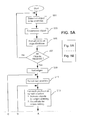
- a method 500 of rendering graphical objects is described below with reference to Figs. 5A and 5B.
- the principles of the method 500 have general applicability to the rendering of graphical objects.
- the steps of the method 500 are described with reference to the rendering of graphical objects for printing on a page. It is not intended that the present invention be limited to the described arrangement.
- the method 500 may have application to the rendering of graphical objects for display on a liquid-crystal or other display device, which has the characteristic that dots that comprise the displayed image are fully present or fully absent.
- Such display devices are often driven by embedded computing systems having extremely constrained memory and performance.
- the method 500 is preferably practiced using a general-purpose computer system 100, such as that shown in Fig. 1 wherein the processes of Figs. 2 to 5B may be implemented as software, such as an application program executing within the computer system 100.
- the steps of the method 500 described below are effected by instructions in the software that are carried out by the computer.
- the instructions may be formed as one or more code modules, each for performing one or more particular tasks.
- the software may also be divided into two separate parts, in which a first part performs the method 500 and a second part manages a user interface between the first part and the user.
- the software may be stored in a computer readable medium, including the storage devices described below, for example.
- the software is loaded into the computer from the computer readable medium, and then executed by the computer.
- a computer readable medium having such software or computer program recorded on it is a computer program product.
- the use of the computer program product in the computer preferably effects an advantageous apparatus for implementing the arrangements described here in.
- the computer system 100 comprises a computer module 101, input devices such as a keyboard 102 and mouse 103, output devices including a printer 115 and a display device 114.
- a Modulator-Demodulator (Modem) transceiver device 116 is used by the computer module 101 for communicating to and from a communications network 120, for example connectable via a telephone line 121 or other functional medium.
- the modem 116 can be used to obtain access to the Internet, and other network systems, such as a Local Area Network (LAN) or a Wide Area Network (WAN).
- LAN Local Area Network
- WAN Wide Area Network
- the computer module 101 typically includes at least one processor unit 105, a memory unit 106, for example formed from semiconductor random access memory (RAM) and read only memory (ROM), input/output (I/O) interfaces including a video interface 107, and an I/O interface 113 for the keyboard 102 and mouse 103 and optionally a joystick (not illustrated), and an interface 108 for the modem 116.
- a storage device 109 is provided and typically includes a hard disk drive 110 and a floppy disk drive 111.
- a magnetic tape drive (not illustrated) may also be used.
- a CD-ROM drive 112 is typically provided as a non-volatile source of data.
- the components 105 to 113 of the computer module 101 typically communicate via an interconnected bus 104 and in a manner, which results in a conventional mode of operation of the computer system 100 known to those in the relevant art.
- Examples of computers on which the described arrangements can be practiced include IBM-PC's and compatibles, Sun Sparcstations or alike computer systems evolved therefrom.
- the application program is resident on the hard disk drive 110 and read and controlled in its execution by the processor 105. Intermediate storage of the program and any data fetched from the network 120 may be accomplished using the semiconductor memory 106, possibly in concert with the hard disk drive 110. In some instances, the application program may be supplied to the user encoded on a CD-ROM or floppy disk and read via the corresponding drive 112 or 111, or alternatively may be read by the user from the network 120 via the modem device 116. Still further, the software can also be loaded into the computer system 100 from other computer readable media.
- the term "computer readable medium” as used herein refers to any storage or transmission medium that participates in providing instructions and/or data to the computer system 100 for execution and/or processing.
- Examples of storage media include floppy disks, magnetic tape, CD-ROM, a hard disk drive, a ROM or integrated circuit, a magneto-optical disk, or a computer readable card such as a PCMCIA card and the like, whether or not such devices are internal or external of the computer module 101.
- Examples of transmission media include radio or infra-red transmission channels as well as a network connection to another computer or networked device, and the Internet or Intranets including email transmissions and information recorded on websites and the like.
- the steps of the method 500 integrate a halftone process with an existing host rendering system executing on the computer system 100.
- areas of constant colour are converted to a tiled representation, which can be used to represent the halftoned colour for any area of an image no matter how large.
- the method 500 improves the performance of the host rendering system for a wide range of output pages.
- bitmap image data can be converted into a corresponding halftoned representation on demand, thus saving considerable memory during the rendering of the corresponding image.
- the steps of the method 500 are performed on a scanline basis as a rendering system generates runs of pixel data from one edge crossing to the next, and are performed on demand.
- an image is rendered utilizing a display list or array of graphical objects representing the image where the objects are converted into a halftoned representation before being output for printing on a page.
- dithering is performed on the objects of the image before being output.
- error diffusion, binarization or any other halftoning technique known to those in the relevant art can be performed on the objects of the image.
- the generation of an output in such a manner reduces the work typically required in halftoning areas of objects and does not require the use of a frame buffer.
- the method 500 also performs color conversion on graphical objects if required.
- Graphical objects to be rendered using the method 500 can define areas of flat or blended color, bitmap image data, or tiled image data, for example.
- halftoned data can be pre-calculated for different object types (e.g. text objects, graphic objects, image objects) and the halftoned data can be stored along with original input data representing the graphical objects to be rendered.
- object types e.g. text objects, graphic objects, image objects
- the halftoned data can be stored along with original input data representing the graphical objects to be rendered.
- the halftoned data can be based on any dithering technique known to those in the relevant art.
- the halftoned data can be based on error diffusion, binarisation or any other halftoning technique known to those in the relevant art.
- halftoned data associated with the opaque object can be used to directly render the image rather than applying transparency as a separate post-rendering step, as is often performed in conventional rendering methods.
- Rendering of flat coloured objects using the method 500 greatly reduces the number of pixels that must be color converted and halftoned compared to conventional rendering methods. Further, only the area of an object of the image that is actually visible is processed. Thus, the amount of memory used to render graphical objects is reduced over, for example, a conventional printer rendering method requiring a temporary frame store.
- the method 500 can reduce the size of an associated spool file significantly.
- the reduction in the size of the spool file is realised since the original contone bitmap data is replaced with equivalent halftoned data before the spooling of the display list to the printer 115.
- an image 200 comprising objects 203, 204 and 205, for example, is rendered by generating edge-crossing information during a scan of the image 200.
- the edge-crossing information is extracted from a list of graphical objects 202, representing the image 200, where the list 202 is pre-ordered by depth (i.e. z-order).
- the edge crossing information is then used to generate runs of pixels to be output to a printer (e.g. the printer 115) for printing on a page 210.
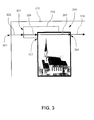
- Fig 3 shows a portion of the image 200 where a scanline 301 crosses edges 322, 323 and 324 resulting in pixel runs 325, 326, 327 and 328.
- the method 500 can be utilised to render flat colours (i.e. areas of constant colour) (e.g. the object 203), colors interpolated between two endpoints (e.g. the object 204), and bitmap image data (e.g. the bitmap image 205).
- the method 500 can also be utilised to render bitmap image data that is repeated or tiled throughout an area being rendered. In particular, areas of constant color are converted into a tiled representation, which is then used in a halftoning operation for that area of the image.
- the method 500 is preferably implemented as an application program being resident on the hard disk drive 110 and being read and controlled in its execution by the processor 105.
- the method 500 begins at step 501, where the processor 105 detects a first graphical object to be rendered.
- the graphical object is decomposed by the processor 105 into a set of edges defining the object, priority information for the object, a raster operation for the object and a corresponding winding rule for the object.
- the method 500 continues at the next step 505 where the set of edges defining the object are added to an edge database configured within memory 106.
- the method 500 continues at the next step 509. Otherwise, the method 500 returns to step 501.
- the edges stored in the edge database configured within memory 106 are sorted in ascending y-coordinate, ascending x-coordinate, and ascending priority order (ie z-order).
- the processor 105 selects a scanline for the image to be rendered. For each pixel run on the scanline selected at step 511, objects having an edge entered by the scanline are activated and objects having an edge exited by the scanline are de-activated, at the next step 513.
- the method 500 continues at the next step 514, where if the highest priority active object for a current pixel run is opaque, then the method 500 continues at the next step 515. Otherwise, the method 500 proceeds to step 517.
- step 515 if fill data for the highest priority object has been halftoned, then the method 500 proceeds to step 519. Otherwise, the method 500 proceeds to step 516 where halftone information is generated for the fill data of the object and is stored in memory 106 together with the original fill data for the object. The method 500 continues at the next step 519, where the pixel run is output, using the halftoned fill data for the object, for printing on a printer (e.g. the printer 105).
- a printer e.g. the printer 105
- step 517 fill data for all visible objects of the current pixel run are composited together to generate data for the pixel run. Also at step 517, the data for the current pixel run is halftoned and then output for printing.
- step 521 if all pixel runs have been processed for the current scanline, then the method 500 continues at the next step 523. Otherwise, the method 500 returns to step 513.
- step 523 if all scanlines have been processed for the image to be rendered, then the method 500 concludes. Otherwise, the method 500 returns to step 511 where a next scanline is selected by the processor 105.
- scanlines are preferably generated downwards from the top of a page 210 to be rendered.
- scanlines can also be generated from the bottom of the page 210.
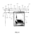
- pixel runs 431, 450 and 451 are generated for the scanline 401
- pixel runs 434, 435, 436 and 437 are generated for the scanline 402. Any scanlines prior to scanline 401 do not intersect any of the graphical objects 203 or 205, so pixel runs generated by the scanlines prior to the scanline 401 do not result in any halftoned output. This is also true for the pixel run 431.
- the first non-white graphical object encountered during the scanline process is the flat fill object 203.
- the object 203 is converted into a tiled image 433 representing a portion of the object 203 and all subsequent pixel runs within the flat fill object 203 from the scanline 401 onwards, use the tiled image 433 to generate halftoned output directly for printing on the printer 115.
- Generating pixel runs in this manner results in an improvement in both speed and efficiency over conventional methods of rendering since tiled images can be rendered by a computer system (e.g. the computer system 100) with little overhead.
- the pixel run 434 will be white and the pixel run 435 will utilise the tiled image 433.
- a portion of the image object 205 is converted into a halftoned image 438 (i.e. represented by the shaded area) as seen within the image object 205.
- the halftone image 438 is used for all subsequent pixel runs within the image object 205 assuming that the image object 205 is fully opaque in the region of overlap 457 (i.e. represented by the phantom line) between the object 203 and the object 205.
- the region of overlap 457 is composited using the original data of the flat fill object 203 and the image object 205.
- the result of the compositing operation is then halftoned. It is noted however that such compositing is only required within the region of overlap 457 and then only if the corresponding compositing or logical raster operation requires such action.
- the original bitmap data for the image object 203 can be discarded after the halftoned image is generated.
- Such action results in a large reduction in memory usage for a 24-bit RGB contone image, for example.
- the original data for such an RGB image uses three bytes per pixel, while a four bit per pixel halftoned representation of the image at the same resolution packs two pixels into a byte, providing an improvement of 6:1.
- the steps of the method 500 are preferably performed as the processor 105 generates runs of pixel data from one edge crossing to the next.
- the method 500 can alternatively be implemented in dedicated hardware such as one or more integrated circuits performing the functions or sub functions of Fig. 5.
- dedicated hardware may include graphic processors, digital signal processors, or one or more microprocessors and associated memories.
- the aforementioned method comprises a particular control flow. There are many other variants of the method which use different control flows without departing the spirit or scope of the invention. Furthermore one or more of the steps of the methods may be performed in parallel rather than sequentially.
Landscapes
- Engineering & Computer Science (AREA)
- Physics & Mathematics (AREA)
- Theoretical Computer Science (AREA)
- General Physics & Mathematics (AREA)
- Geometry (AREA)
- Computer Graphics (AREA)
- Human Computer Interaction (AREA)
- General Engineering & Computer Science (AREA)
- Image Processing (AREA)
- Record Information Processing For Printing (AREA)
- Image Generation (AREA)
- Ink Jet (AREA)
Abstract
Description
Claims (13)
- A method of creating an image, said image being formed by rendering a plurality of graphical objects on a scanline basis, where each scanline comprises at least one run of pixels, said method comprising the steps of:(I) forming an array representing said graphical objects of said image, said array being sorted in an order from a top-most graphical object to a bottom-most graphical object; and(II) for each scanline of said image and for each run of pixels of said scanline:(II) (i) traversing said array to determine objects contributing to said run of pixels; and(II) (ii) compositing data associated with one or more of said contributing objects and halftoning the composited data to generate said run of pixels.
- A method according to claim 1, wherein step (II)(ii) includes the further sub-steps of:(II)(ii)(a) determining if a top-most contributing object corresponding to said run of pixels is opaque; and(II)(ii)(b) halftoning pixel data representing said top-most contributing object to generate said run of pixels, if said top-most contributing object is opaque.
- A method according to claim 1, further comprising the step of decomposing said objects into their constituent attributes including at least one edge of a corresponding object.
- A method according to claim 4, wherein step (II)(i) includes the further sub-step of traversing a further array to determine edges of objects defining said run of pixels.
- A method according to claim 4, further comprising the step of determining a contribution of an object depending on which edges of said contributing objects are crossed by a current scanline.
- A method according to claim 1, wherein step (II)(ii) includes the further sub-step of using previously halftoned data to generate said run of pixels.
- An apparatus for creating an image, said image being formed by rendering a plurality of graphical objects on a scanline basis, where each scanline comprises at least one run of pixels, said apparatus comprising:array forming means for forming an array representing said graphical objects of said image, said array being sorted in an order from a top-most graphical object to a bottom-most graphical object;traversing means for traversing said array to determine objects contributing to a run of pixels of a scanline; andcompositing means for compositing data associated with one or more of said contributing objects and halftoning the composited data to generate said run of pixels.
- The apparatus according to claim 7, wherein said compositing means further includes:determining means for determining if a top-most contributing object corresponding to said run of pixels is opaque; andhalftoning means for halftoning pixel data representing said top-most contributing object to generate said run of pixels, if said top-most contributing object is opaque.
- The apparatus according to claim 7, further comprising the step of decomposing means for decomposing said objects into their constituent attributes including at least one edge of a corresponding object.
- The apparatus according to claim 7, further comprising means for traversing a further array to determine edges of objects defining said run of pixels.
- The apparatus according to claim 7, further comprising means for determining a contribution of an object depending on which edges of said contributing objects are crossed by a current scanline.
- A computer program for creating an image, said image being formed by rendering a plurality of graphical objects on a scanline basis, wherein each scanline comprises at least one run of pixels, said program comprising code for implementing the steps of a method according to any one of claims 1 to 6.
- A computer readable medium, having a program recorded thereon according to claim 12.
Applications Claiming Priority (2)
| Application Number | Priority Date | Filing Date | Title |
|---|---|---|---|
| AUPS1342A AUPS134202A0 (en) | 2002-03-25 | 2002-03-25 | System and method for optimizing halftoning printer performance |
| AUPS134202 | 2002-03-25 |
Publications (3)
| Publication Number | Publication Date |
|---|---|
| EP1351196A2 true EP1351196A2 (en) | 2003-10-08 |
| EP1351196A3 EP1351196A3 (en) | 2005-10-19 |
| EP1351196B1 EP1351196B1 (en) | 2011-01-19 |
Family
ID=3834936
Family Applications (1)
| Application Number | Title | Priority Date | Filing Date |
|---|---|---|---|
| EP03251745A Expired - Lifetime EP1351196B1 (en) | 2002-03-25 | 2003-03-20 | A method and apparatus for creating an image |
Country Status (7)
| Country | Link |
|---|---|
| US (2) | US7286142B2 (en) |
| EP (1) | EP1351196B1 (en) |
| JP (1) | JP2004122746A (en) |
| KR (1) | KR100633874B1 (en) |
| CN (1) | CN1254772C (en) |
| AU (1) | AUPS134202A0 (en) |
| DE (1) | DE60335762D1 (en) |
Cited By (1)
| Publication number | Priority date | Publication date | Assignee | Title |
|---|---|---|---|---|
| EP1612737A3 (en) * | 2004-06-30 | 2008-03-12 | Canon Kabushiki Kaisha | Method of rendering graphic objects |
Families Citing this family (5)
| Publication number | Priority date | Publication date | Assignee | Title |
|---|---|---|---|---|
| AU2005201930B2 (en) * | 2005-05-06 | 2009-02-19 | Canon Kabushiki Kaisha | Simplification of alpha compositing in the presence of transfer functions |
| US7517039B2 (en) * | 2005-09-19 | 2009-04-14 | Marvell International Technology Ltd. | Enabling increased print speed by eliminating nozzle firing sequencing |
| AU2007203061A1 (en) * | 2007-06-29 | 2009-01-15 | Canon Kabushiki Kaisha | Efficient banded hybrid rendering |
| AU2009202377A1 (en) * | 2009-06-15 | 2011-01-06 | Canon Kabushiki Kaisha | Combining overlapping objects |
| AU2009240860B2 (en) * | 2009-11-26 | 2011-12-22 | Canon Kabushiki Kaisha | Determining composite colour for dithered object and contone object |
Family Cites Families (28)
| Publication number | Priority date | Publication date | Assignee | Title |
|---|---|---|---|---|
| US5075779A (en) * | 1990-04-27 | 1991-12-24 | Intergraph Corporation | Apparatus and method for interpreting image data for use in a raster plotter |
| DE69117112T2 (en) * | 1990-08-08 | 1996-06-27 | Peerless Group | Image rendering method and apparatus |
| EP0607136B1 (en) * | 1991-10-10 | 1998-04-29 | Hewlett-Packard Company | Graphics output system with bounded updating |
| US5668931A (en) * | 1993-03-31 | 1997-09-16 | Dermer; Richard A. | Method for automatic trap selection for correcting for plate misregistration in color printing |
| US5838334A (en) | 1994-11-16 | 1998-11-17 | Dye; Thomas A. | Memory and graphics controller which performs pointer-based display list video refresh operations |
| DE19513105A1 (en) * | 1995-04-07 | 1996-10-10 | Hell Ag Linotype | Procedure for generating a contone map |
| US6268859B1 (en) | 1995-06-06 | 2001-07-31 | Apple Computer, Inc. | Method and system for rendering overlapping opaque graphical objects in graphic imaging systems |
| JPH0918703A (en) | 1995-06-29 | 1997-01-17 | Canon Inc | Image forming device |
| US6137589A (en) | 1995-09-20 | 2000-10-24 | Hewlett-Packard Company | Efficient storage of dithered raster image data in a printer or the like |
| US6046748A (en) | 1996-06-27 | 2000-04-04 | Peerless Systems Corporation | Cooperative filter and raster operation evaluation model |
| US5949964A (en) | 1997-06-17 | 1999-09-07 | Hewlett-Packard Company | Method and apparatus for halftoning of images in a printer |
| US5966467A (en) | 1997-09-12 | 1999-10-12 | Xerox Corporation | System for compressing and decompressing binary representations of dithered images |
| JP3413829B2 (en) | 1997-11-18 | 2003-06-09 | 富士ゼロックス株式会社 | Drawing processing apparatus and method |
| US6049339A (en) * | 1997-12-22 | 2000-04-11 | Adobe Systems Incorporated | Blending with planar maps |
| US6313847B1 (en) * | 1997-12-22 | 2001-11-06 | Adobe Systems Incorporated | Blending graphics objects in a frame buffer |
| WO2000000951A1 (en) | 1998-06-29 | 2000-01-06 | Honeywell Inc. | Method of and system for detecting and rendering of graphic elements |
| US6828985B1 (en) | 1998-09-11 | 2004-12-07 | Canon Kabushiki Kaisha | Fast rendering techniques for rasterised graphic object based images |
| JP4365950B2 (en) | 1998-09-11 | 2009-11-18 | キヤノン株式会社 | Graphic object processing method and apparatus for high-speed raster format rendering |
| US6201614B1 (en) * | 1998-12-24 | 2001-03-13 | Electronics For Imaging, Inc. | Dithered image compression system |
| JP2000235643A (en) | 1999-02-17 | 2000-08-29 | Victor Co Of Japan Ltd | Picture synthesis method |
| US6369830B1 (en) | 1999-05-10 | 2002-04-09 | Apple Computer, Inc. | Rendering translucent layers in a display system |
| DE10012521C2 (en) * | 2000-03-15 | 2002-12-19 | Heidelberger Druckmasch Ag | Process for compressing print data |
| US6781600B2 (en) * | 2000-04-14 | 2004-08-24 | Picsel Technologies Limited | Shape processor |
| US6850338B1 (en) * | 2000-05-12 | 2005-02-01 | International Business Machines Corporation | Method, system, program, and data structure for generating raster objects |
| US6774913B1 (en) * | 2000-05-15 | 2004-08-10 | International Business Machines Corporation | System, method, and program for selectively merging partial objects |
| AUPQ758000A0 (en) | 2000-05-17 | 2000-06-08 | Canon Kabushiki Kaisha | Processing pixels of a digital image |
| US6891536B2 (en) * | 2001-11-30 | 2005-05-10 | Canon Kabushiki Kaisha | Method of determining active priorities |
| JP3855873B2 (en) * | 2002-07-31 | 2006-12-13 | 株式会社日立製作所 | Linear drive device and manufacturing apparatus using the same |
-
2002
- 2002-03-25 AU AUPS1342A patent/AUPS134202A0/en not_active Abandoned
-
2003
- 2003-03-20 DE DE60335762T patent/DE60335762D1/en not_active Expired - Lifetime
- 2003-03-20 KR KR1020030017445A patent/KR100633874B1/en not_active Expired - Fee Related
- 2003-03-20 EP EP03251745A patent/EP1351196B1/en not_active Expired - Lifetime
- 2003-03-21 US US10/393,249 patent/US7286142B2/en not_active Expired - Lifetime
- 2003-03-25 CN CNB03108236XA patent/CN1254772C/en not_active Expired - Fee Related
- 2003-03-25 JP JP2003083616A patent/JP2004122746A/en active Pending
-
2007
- 2007-01-05 US US11/620,283 patent/US7477265B2/en not_active Expired - Fee Related
Cited By (2)
| Publication number | Priority date | Publication date | Assignee | Title |
|---|---|---|---|---|
| EP1612737A3 (en) * | 2004-06-30 | 2008-03-12 | Canon Kabushiki Kaisha | Method of rendering graphic objects |
| US7755629B2 (en) | 2004-06-30 | 2010-07-13 | Canon Kabushiki Kaisha | Method of rendering graphic objects |
Also Published As
| Publication number | Publication date |
|---|---|
| DE60335762D1 (en) | 2011-03-03 |
| CN1254772C (en) | 2006-05-03 |
| JP2004122746A (en) | 2004-04-22 |
| US20070103469A1 (en) | 2007-05-10 |
| KR100633874B1 (en) | 2006-10-13 |
| US7286142B2 (en) | 2007-10-23 |
| US7477265B2 (en) | 2009-01-13 |
| CN1447286A (en) | 2003-10-08 |
| EP1351196A3 (en) | 2005-10-19 |
| EP1351196B1 (en) | 2011-01-19 |
| KR20030077986A (en) | 2003-10-04 |
| US20030227463A1 (en) | 2003-12-11 |
| AUPS134202A0 (en) | 2002-05-09 |
Similar Documents
| Publication | Publication Date | Title |
|---|---|---|
| EP1359545B1 (en) | Process for rendering mixed raster content files | |
| EP1528510B1 (en) | Advanced Shape Processor | |
| US5929866A (en) | Adjusting contrast in anti-aliasing | |
| US6313847B1 (en) | Blending graphics objects in a frame buffer | |
| US5852679A (en) | Image processing apparatus and method | |
| US7277095B2 (en) | Method of rendering graphical objects | |
| US6654147B1 (en) | Anti-aliasing for digital printing | |
| US7286142B2 (en) | System and method for optimising halftoning printer performance | |
| JPH05143742A (en) | Vector image drawing device | |
| US6738071B2 (en) | Dynamically anti-aliased graphics | |
| JP3689574B2 (en) | Image processing method and apparatus, image processing system, and recording medium | |
| US6430321B1 (en) | Text enhancement | |
| JP3009525B2 (en) | Vector image drawing equipment | |
| AU2003201329B2 (en) | A System and Method for Optimising Halftoning Printer Performance | |
| EP0616463A1 (en) | Method and apparatus for smoothed scaling of facsimile images | |
| US7345790B2 (en) | Method and apparatus for simulating 2 bit-per-pel printing on a bi-level printer using intelligent double dotting | |
| US20050195220A1 (en) | Compositing with clip-to-self functionality without using a shape channel | |
| JP3294249B2 (en) | Image processing device | |
| AU2008264239A1 (en) | Text processing in a region based printing system | |
| AU2007240228A1 (en) | Improved hybrid rendering | |
| JPH0535879A (en) | Vector image drawing device | |
| AU2003248383A1 (en) | Method of Rendering Halftoned Data | |
| HK1058849B (en) | Process for rendering mixed raster content files |
Legal Events
| Date | Code | Title | Description |
|---|---|---|---|
| PUAI | Public reference made under article 153(3) epc to a published international application that has entered the european phase |
Free format text: ORIGINAL CODE: 0009012 |
|
| AK | Designated contracting states |
Kind code of ref document: A2 Designated state(s): AT BE BG CH CY CZ DE DK EE ES FI FR GB GR HU IE IT LI LU MC NL PT RO SE SI SK TR |
|
| AX | Request for extension of the european patent |
Extension state: AL LT LV MK |
|
| PUAL | Search report despatched |
Free format text: ORIGINAL CODE: 0009013 |
|
| AK | Designated contracting states |
Kind code of ref document: A3 Designated state(s): AT BE BG CH CY CZ DE DK EE ES FI FR GB GR HU IE IT LI LU MC NL PT RO SE SI SK TR |
|
| AX | Request for extension of the european patent |
Extension state: AL LT LV MK |
|
| 17P | Request for examination filed |
Effective date: 20060419 |
|
| AKX | Designation fees paid |
Designated state(s): DE FR GB IT |
|
| 17Q | First examination report despatched |
Effective date: 20070403 |
|
| GRAP | Despatch of communication of intention to grant a patent |
Free format text: ORIGINAL CODE: EPIDOSNIGR1 |
|
| GRAS | Grant fee paid |
Free format text: ORIGINAL CODE: EPIDOSNIGR3 |
|
| GRAA | (expected) grant |
Free format text: ORIGINAL CODE: 0009210 |
|
| AK | Designated contracting states |
Kind code of ref document: B1 Designated state(s): DE FR GB IT |
|
| REG | Reference to a national code |
Ref country code: GB Ref legal event code: FG4D |
|
| REF | Corresponds to: |
Ref document number: 60335762 Country of ref document: DE Date of ref document: 20110303 Kind code of ref document: P |
|
| REG | Reference to a national code |
Ref country code: DE Ref legal event code: R096 Ref document number: 60335762 Country of ref document: DE Effective date: 20110303 |
|
| PLBE | No opposition filed within time limit |
Free format text: ORIGINAL CODE: 0009261 |
|
| STAA | Information on the status of an ep patent application or granted ep patent |
Free format text: STATUS: NO OPPOSITION FILED WITHIN TIME LIMIT |
|
| REG | Reference to a national code |
Ref country code: FR Ref legal event code: ST Effective date: 20111130 |
|
| 26N | No opposition filed |
Effective date: 20111020 |
|
| PG25 | Lapsed in a contracting state [announced via postgrant information from national office to epo] |
Ref country code: IT Free format text: LAPSE BECAUSE OF FAILURE TO SUBMIT A TRANSLATION OF THE DESCRIPTION OR TO PAY THE FEE WITHIN THE PRESCRIBED TIME-LIMIT Effective date: 20110119 |
|
| PG25 | Lapsed in a contracting state [announced via postgrant information from national office to epo] |
Ref country code: FR Free format text: LAPSE BECAUSE OF NON-PAYMENT OF DUE FEES Effective date: 20110331 |
|
| REG | Reference to a national code |
Ref country code: DE Ref legal event code: R097 Ref document number: 60335762 Country of ref document: DE Effective date: 20111020 |
|
| PGFP | Annual fee paid to national office [announced via postgrant information from national office to epo] |
Ref country code: GB Payment date: 20190327 Year of fee payment: 17 |
|
| PGFP | Annual fee paid to national office [announced via postgrant information from national office to epo] |
Ref country code: DE Payment date: 20190531 Year of fee payment: 17 |
|
| REG | Reference to a national code |
Ref country code: DE Ref legal event code: R119 Ref document number: 60335762 Country of ref document: DE |
|
| PG25 | Lapsed in a contracting state [announced via postgrant information from national office to epo] |
Ref country code: DE Free format text: LAPSE BECAUSE OF NON-PAYMENT OF DUE FEES Effective date: 20201001 |
|
| GBPC | Gb: european patent ceased through non-payment of renewal fee |
Effective date: 20200320 |
|
| PG25 | Lapsed in a contracting state [announced via postgrant information from national office to epo] |
Ref country code: GB Free format text: LAPSE BECAUSE OF NON-PAYMENT OF DUE FEES Effective date: 20200320 |