EP1351193A2 - Methods and apparatus for weighting projection data - Google Patents
Methods and apparatus for weighting projection data Download PDFInfo
- Publication number
- EP1351193A2 EP1351193A2 EP03251937A EP03251937A EP1351193A2 EP 1351193 A2 EP1351193 A2 EP 1351193A2 EP 03251937 A EP03251937 A EP 03251937A EP 03251937 A EP03251937 A EP 03251937A EP 1351193 A2 EP1351193 A2 EP 1351193A2
- Authority
- EP
- European Patent Office
- Prior art keywords
- computer
- region
- regions
- sub
- detector
- Prior art date
- Legal status (The legal status is an assumption and is not a legal conclusion. Google has not performed a legal analysis and makes no representation as to the accuracy of the status listed.)
- Withdrawn
Links
Images




Classifications
-
- G—PHYSICS
- G06—COMPUTING OR CALCULATING; COUNTING
- G06T—IMAGE DATA PROCESSING OR GENERATION, IN GENERAL
- G06T12/00—Tomographic reconstruction from projections
- G06T12/10—Image preprocessing, e.g. calibration, positioning of sources or scatter correction
-
- A—HUMAN NECESSITIES
- A61—MEDICAL OR VETERINARY SCIENCE; HYGIENE
- A61B—DIAGNOSIS; SURGERY; IDENTIFICATION
- A61B6/00—Apparatus or devices for radiation diagnosis; Apparatus or devices for radiation diagnosis combined with radiation therapy equipment
- A61B6/02—Arrangements for diagnosis sequentially in different planes; Stereoscopic radiation diagnosis
- A61B6/027—Arrangements for diagnosis sequentially in different planes; Stereoscopic radiation diagnosis characterised by the use of a particular data acquisition trajectory, e.g. helical or spiral
Definitions
- This invention relates to computed tomographic (CT) imaging, and more particularly to methods and apparatus for weighting projection data acquired using a multi-slice CT imaging system.
- CT computed tomographic
- a method for weighting projection data includes selecting a region that includes a plurality of projection data samples, dividing the region into a plurality of equally sized sub-regions, and weighting the equally sized sub-regions using a location dependent z-smoothing weighting function.
- a computer for weighting projection data acquired using a medical imaging system includes a radiation source and a detector.
- the computer is programmed to select a region that includes a plurality of projection data samples, divide the region into a plurality of equally sized sub-regions, and weight the equally sized sub-regions using a location dependent z-smoothing weighting function.
- a computed tomographic (CT) imaging system for weighting projection data.
- the CT system includes a radiation source, a detector array, and a computer coupled to the detector array and the radiation source and configured to select a region that includes a plurality of projection data samples, divide the region into a plurality of equally sized sub-regions, and weight the equally sized sub-regions using a location dependent z-smoothing weighting function.
- an x-ray source projects a fan-shaped beam which is collimated to lie within an X-Y plane of a Cartesian coordinate system and generally referred to as an "imaging plane".
- the x-ray beam passes through an object being imaged, such as a patient.
- the beam after being attenuated by the object, impinges upon an array of radiation detectors.
- the intensity of the attenuated radiation beam received at the detector array is dependent upon the attenuation of an x-ray beam by the object.
- Each detector element of the array produces a separate electrical signal that is a measurement of the beam attenuation at the detector location.
- the attenuation measurements from all the detectors are acquired separately to produce a transmission profile.
- the x-ray source and the detector array are rotated with a gantry within the imaging plane and around the object to be imaged such that the angle at which the x-ray beam intersects the object constantly changes.
- a group of x-ray attenuation measurements, i.e., projection data, from the detector array at one gantry angle is referred to as a "view”.
- a "scan" of the object comprises a set of views made at different gantry angles, or view angles, during one revolution of the x-ray source and detector.
- the projection data is processed to construct an image that corresponds to a two dimensional slice taken through the object.
- One method for reconstructing an image from a set of projection data is referred to in the art as the filtered back projection technique. This process converts the attenuation measurements from a scan into integers called “CT numbers” or “Hounsfield units”, which are used to control the brightness of a corresponding pixel on a cathode ray tube display.
- a "helical” scan may be performed.
- the patient is moved while the data for the prescribed number of slices is acquired.
- Such a system generates a single helix from a fan beam helical scan for a single slice CT.
- multiple helixes are generated from a fan beam helical scan.
- the helix mapped out by the fan beam yields projection data from which images in each prescribed slice may be reconstructed.
- Reconstruction algorithms for helical scanning typically use helical weighing algorithms that weight the collected data as a function of view angle and detector channel index. Specifically, prior to a filtered back projection process, the data is weighted according to a helical weighing factor, which is a function of both the gantry angle and detector angle. The weighted data is then processed to generate CT numbers and to construct an image that corresponds to a two dimensional slice taken through the object.
- the phrase "reconstructing an image” is not intended to exclude embodiments of the present invention in which data representing an image is generated but a viewable image is not. However, many embodiments generate (or are configured to generate) at least one viewable image.
- a multi-slice scanning imaging system for example, computed tomography (CT) imaging system 10
- CT computed tomography
- Gantry 12 has an x-ray source 14 that projects a beam of x-rays 16 toward a detector array 18 on the opposite side of gantry 12.
- Detector array 18 is formed by a plurality of detector rows (not shown) including a plurality of detector elements 20 which together sense the projected x-rays that pass through an object, such as a medical patient 22.
- Each detector element 20 produces an electrical signal that represents the intensity of an impinging x-ray beam and hence the attenuation of the beam as it passes through object or patient 22.
- multislice detector array 18 includes a plurality of parallel detector rows of detector elements 20 so that projection data corresponding to a plurality of quasi-parallel or parallel slices can be acquired simultaneously during a scan.
- Control mechanism 26 includes an x-ray controller 28 that provides power and timing signals to x-ray source 14 and a gantry motor controller 30 that controls the rotational speed and position of gantry 12.
- a data acquisition system (DAS) 32 in control mechanism 26 samples analog data from detector elements 20 and converts the data to digital signals for subsequent processing.
- An image reconstructor 34 receives sampled and digitized x-ray data from DAS 32 and performs high-speed image reconstruction. The reconstructed image is applied as an input to a computer 36 which stores the image in a mass storage device 38.
- DAS data acquisition system
- Computer 36 also receives commands and scanning parameters from an operator via console 40 that has a keyboard.
- An associated cathode ray tube display 42 allows the operator to observe the reconstructed image and other data from computer 36.
- the operator supplied commands and parameters are used by computer 36 to provide control signals and information to DAS 32, x-ray controller 28 and gantry motor controller 30.
- computer 36 operates a table motor controller 44 which controls a motorized table 46 to position patient 22 in gantry 12. Particularly, table 46 moves portions of patient 22 through gantry opening 48.
- computer 36 includes a device 50, for example, a floppy disk drive or CD-ROM drive, for reading instructions and/or data from a computer-readable medium 52, such as a floppy disk or CD-ROM.
- computer 36 executes instructions stored in firmware (not shown).
- Computer 36 is programmed to perform functions described herein, accordingly, as used herein, the term computer is not limited to just those integrated circuits referred to in the art as computers, but broadly refers to computers, processors, microcontrollers, microcomputers, programmable logic controllers, application specific integrated circuits, and other programmable circuits.
- Figure 3 is a flow diagram of a method 60 for weighting projection data.
- Method 60 includes selecting 62 a region that includes a plurality of projection data samples, dividing 64 the region into a plurality of equally sized sub-regions, and weighting 66 the equally sized sub-regions using a location dependent z-smoothing weighting function.
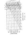
- Figure 4 is a sampling pattern for a plurality of iso-rays of a multi-slice CT.
- the loci of detector 18 (shown in Figure 1) iso-channels are plotted as functions of both a projection angle ⁇ , and detector 18 location on a z axis, to generate a plurality of diagonal lines as shown in Figure 4.
- Detector 18 includes M rows and scans at an N:1 helical pitch to generate a plurality of projection data.
- Selecting 62 a region 70 that includes a plurality of projection data samples includes selecting a plurality of projection data samples that are within 2 ⁇ / N in projection angle ⁇ on either side of a plane of reconstruction (POR) 72.
- a size of region 70 is selected based on a desired smoothing.
- Dividing 64 region 70 into a plurality of equally sized sub-regions 74 includes dividing region 70 of each detector row into four sub-regions 74, wherein each sub-region 74 covers a projection angle ⁇ range of approximately ⁇ / N , as shown in Figure 4. In another embodiment, a region 70 greater than 2 ⁇ / N in projection angle ⁇ can be selected and then divided into greater than four sub-regions 74.
- all regions 70 in sinogram space which are conjugate include the same shape and are bounded by ⁇ n,k - ⁇ lines.
- weighting 66 sub-regions 74 using a location dependent z-smoothing weighting function w k ( ⁇ , ⁇ ) includes selecting the weighting function that satisfies two conditions.
- the weighting function, w k ( ⁇ , ⁇ ) function is an even function of fan angle ⁇ parallel to the sub-region boundaries, and the weighting function, w k ( ⁇ , ⁇ ) preserves a summation unity.
- + ⁇ b 2( ⁇ m + ⁇ b ) , ⁇ n ( ⁇ ) [ ⁇ -( ⁇ n,k - ⁇ )] N ⁇ ,
- ⁇ b is set to 0.48.
- the weighting function is uniform across all channels.
- Figure 5 is an image of a weighting function for one of the rows in an eight-row detector.
- Figure 6 is a contour plot of the weighting function shown in Figure 5 which illustrates the weighting function of one of the detector rows (all rows have identical weighting function except a shift in ⁇ ) over a sub-set of view angles in which the weighting function is non-zero.
- Figure 7 is a scan reconstructed with a known reconstruction algorithm.
- Figure 8 is a scan reconstructed with the algorithm described herein. The algorithm was applied to a patient scan with known helical interpolation and cone beam image artifacts. The scan was reconstructed with both the original reconstruction algorithm as shown in Figure 7 and the location dependent z-smoothing weighting function as shown in Figure 8. Improvement in image quality is apparent. Streaking artifacts near the ribs are nearly completely eliminated.
Landscapes
- Physics & Mathematics (AREA)
- General Physics & Mathematics (AREA)
- Engineering & Computer Science (AREA)
- Theoretical Computer Science (AREA)
- Apparatus For Radiation Diagnosis (AREA)
- Magnetic Resonance Imaging Apparatus (AREA)
Abstract
Description
wherein

Claims (6)
- A computer (36) for weighting projection data acquired using a medical imaging system (10), wherein said imaging system comprises a radiation source (14) and a detector (18), said computer programmed to:select (62) a region (70) that includes a plurality of projection data samples;divide (64) the region into a plurality of equally sized sub-regions (74); andweight (66) the equally sized sub-regions using a location dependent z-smoothing weighting function.
- A computer (36) in accordance with Claim 1 wherein to select (62) a region (70) that includes a plurality of projection data samples, said computer further programmed to select a region that includes a plurality of projection data samples that are within 2π/N in projection angle β on either side of a plane of reconstruction.
- A computer (36) in accordance with Claim 1, said computer further programmed to define a boundary of the sub-regions (74) in accordance with:β0 is a projection angle of a center view;k is a single detector row;M is a number of detector rows;n is a sub-region index; andN is a helical pitch.
- A computer (36) in accordance with Claim 1, said computer further programmed to select a weighting function that is an even function of a fan angle γ parallel to the sub-regions (74) and a summation of the weighting is unity.
- A computer (36) in accordance with Claim 4 wherein to select (62) a region (70) that includes a plurality of projection data samples, said computer further programmed to select a weighting function in accordance with:where:
 γ is a fan angle;Δβ is a projection angle change;n is an index for sub-regions (74); andk is the index for detector rows.
 - A computer (36) in accordance with Claim 1 wherein to weight (66) the equally sized sub-regions (74) using a location dependent z-smoothing weighting function, said computer further programmed to weight the equally sized sub-regions using a location dependent z-smoothing weighting function in accordance with:β is a projection angle;βn, k is a sub-region boundary;γ is a fan angle;γb (0≤γb <∞) is a parameter to adjust the variation of the weighting function from the central channels to the boundary channels; andγm is the maximum detector angle in γ.
Applications Claiming Priority (2)
| Application Number | Priority Date | Filing Date | Title |
|---|---|---|---|
| US113532 | 1993-08-27 | ||
| US10/113,532 US6654442B2 (en) | 2002-03-29 | 2002-03-29 | Methods and apparatus for weighting projection data |
Publications (2)
| Publication Number | Publication Date |
|---|---|
| EP1351193A2 true EP1351193A2 (en) | 2003-10-08 |
| EP1351193A3 EP1351193A3 (en) | 2006-04-12 |
Family
ID=28041032
Family Applications (1)
| Application Number | Title | Priority Date | Filing Date |
|---|---|---|---|
| EP03251937A Withdrawn EP1351193A3 (en) | 2002-03-29 | 2003-03-27 | Methods and apparatus for weighting projection data |
Country Status (3)
| Country | Link |
|---|---|
| US (1) | US6654442B2 (en) |
| EP (1) | EP1351193A3 (en) |
| JP (1) | JP4356061B2 (en) |
Families Citing this family (8)
| Publication number | Priority date | Publication date | Assignee | Title |
|---|---|---|---|---|
| US6873675B2 (en) * | 2002-12-18 | 2005-03-29 | Ge Medical Systems Global Technology Company, Llc | Multi-sector back-off logic algorithm for obtaining optimal slice-sensitive computed tomography profiles |
| US7415145B2 (en) * | 2003-12-30 | 2008-08-19 | General Electric Company | Methods and apparatus for artifact reduction |
| US7050527B2 (en) * | 2004-02-09 | 2006-05-23 | G.E. Medical Systems Global Technology Company, Llc | Methods and apparatus for artifact reduction in cone beam CT image reconstruction |
| US20050201605A1 (en) * | 2004-03-11 | 2005-09-15 | Jianying Li | Methods and apparatus for CT smoothing to reduce artifacts |
| US7173996B2 (en) * | 2004-07-16 | 2007-02-06 | General Electric Company | Methods and apparatus for 3D reconstruction in helical cone beam volumetric CT |
| US8218720B2 (en) * | 2007-03-12 | 2012-07-10 | Varian Medical Systems, Inc. | Method and apparatus to facilitate reconstructing an image using fan-beam data |
| CN107260194B (en) * | 2016-04-08 | 2020-08-28 | 山西锦地裕成医疗设备有限公司 | Method and image reconstruction method and system for positron tomography |
| JP6774813B2 (en) * | 2016-08-12 | 2020-10-28 | 日本電子株式会社 | Image processing equipment, image processing methods, and analyzers |
Family Cites Families (18)
| Publication number | Priority date | Publication date | Assignee | Title |
|---|---|---|---|---|
| US5377250A (en) * | 1992-08-07 | 1994-12-27 | General Electric Company | Reconstruction method for helical scanning computed tomography apparatus with multi-row detector array |
| US5416815A (en) | 1993-07-02 | 1995-05-16 | General Electric Company | Adaptive filter for reducing streaking artifacts in x-ray tomographic images |
| US5515409A (en) | 1994-12-22 | 1996-05-07 | General Electric Company | Helical interpolative algorithm for image reconstruction in a CT system |
| DE19528261C1 (en) | 1995-08-01 | 1996-10-31 | Siemens Ag | Image reconstruction method for computer tomographs |
| US5727041A (en) | 1996-11-13 | 1998-03-10 | General Electric Company | Methods and apparatus for reducing partial volume image artifacts |
| US5812628A (en) | 1996-12-12 | 1998-09-22 | General Electric Company | Methods and apparatus for detecting partial volume image artifacts |
| US6014419A (en) * | 1997-11-07 | 2000-01-11 | Hu; Hui | CT cone beam scanner with fast and complete data acquistion and accurate and efficient regional reconstruction |
| US6115487A (en) | 1998-01-08 | 2000-09-05 | General Electric Company | Correction algorithm for bone-induced spectral artifacts in computed tomograph imaging |
| US6035012A (en) | 1998-05-14 | 2000-03-07 | Gen Electric | Artifact correction for highly attenuating objects |
| US6134292A (en) | 1998-07-13 | 2000-10-17 | General Electric Company | Methods and apparatus for reducing z-axis non-uniformity artifacts |
| US6061419A (en) | 1998-08-25 | 2000-05-09 | General Electric Company | Methods and apparatus for noise compensation in an imaging system |
| US6061420A (en) | 1998-08-25 | 2000-05-09 | General Electric Company | Methods and apparatus for graphical Rx in a multislice imaging system |
| US6215841B1 (en) | 1998-09-29 | 2001-04-10 | General Electric Company | Methods and apparatus for 3D artifact reduction |
| US6233308B1 (en) | 1999-03-19 | 2001-05-15 | General Electric Company | Methods and apparatus for artifact compensation with variable angular sampling |
| US6339632B1 (en) | 1999-12-23 | 2002-01-15 | Ge Medical Systems Global Technology Company, Llc | Multi slice single filtering helical weighting method and apparatus to use the same |
| US6341154B1 (en) * | 2000-06-22 | 2002-01-22 | Ge Medical Systems Global Technology Company, Llc | Methods and apparatus for fast CT imaging helical weighting |
| US6418184B1 (en) * | 2000-12-29 | 2002-07-09 | Ge Medical Systems Global Technology Company, Llc | Helical rowwise view weighting of computed tomographic images |
| US6421411B1 (en) | 2001-05-10 | 2002-07-16 | Ge Medical Systems Global Technology Company, Llc | Methods and apparatus for helical image artifact reduction |
-
2002
- 2002-03-29 US US10/113,532 patent/US6654442B2/en not_active Expired - Lifetime
-
2003
- 2003-03-27 EP EP03251937A patent/EP1351193A3/en not_active Withdrawn
- 2003-03-28 JP JP2003089493A patent/JP4356061B2/en not_active Expired - Fee Related
Also Published As
| Publication number | Publication date |
|---|---|
| EP1351193A3 (en) | 2006-04-12 |
| US20030185337A1 (en) | 2003-10-02 |
| JP2003319932A (en) | 2003-11-11 |
| US6654442B2 (en) | 2003-11-25 |
| JP4356061B2 (en) | 2009-11-04 |
Similar Documents
| Publication | Publication Date | Title |
|---|---|---|
| US6421411B1 (en) | Methods and apparatus for helical image artifact reduction | |
| US6452996B1 (en) | Methods and apparatus utilizing generalized helical interpolation algorithm | |
| US7415145B2 (en) | Methods and apparatus for artifact reduction | |
| US6266388B1 (en) | Methods and apparatus for two-pass cone beam image reconstruction | |
| US6754299B2 (en) | Methods and apparatus for weighting of computed tomography data | |
| EP1321900B1 (en) | Method and apparatus for noise reduction in computed tomographic systems | |
| CN100360089C (en) | Correction for ghosting caused by highly attenuating objects | |
| US6324247B1 (en) | Partial scan weighting for multislice CT imaging with arbitrary pitch | |
| US5606585A (en) | Methods and apparatus for multislice helical image reconstruction in a computer tomography system | |
| US6341154B1 (en) | Methods and apparatus for fast CT imaging helical weighting | |
| US6408042B1 (en) | Methods and apparatus for cone beam artifact suppression in scanning imaging systems | |
| EP1104917B1 (en) | Methods and apparatus for adaptive interpolation reduced view CT scan | |
| US6587537B1 (en) | Methods and apparatus for multi-slice image reconstruction | |
| JP2006314856A (en) | System for generating tomographic images of an object and volumetric computer tomography apparatus | |
| EP1372115B1 (en) | Methods and apparatus for reconstructing an image of an object | |
| US6381297B1 (en) | High pitch reconstruction of multislice CT scans | |
| US6351514B1 (en) | Slice-adaptive multislice helical weighting for computed tomography imaging | |
| EP0989521B1 (en) | Fluoroscopy image reconstruction | |
| US6600802B1 (en) | Image space correction for multi-slice helical reconstruction with z-smoothing | |
| JP2000023966A (en) | Spiral reconstruction algorithm | |
| US6654442B2 (en) | Methods and apparatus for weighting projection data | |
| US6507632B1 (en) | Method and apparatus for reducing artifacts in an image | |
| US6597756B1 (en) | Methods and apparatus for multi-slice image reconstruction | |
| US6418183B1 (en) | Methods and apparatus for two-pass CT imaging | |
| JP4582997B2 (en) | High speed computed tomography method |
Legal Events
| Date | Code | Title | Description |
|---|---|---|---|
| PUAI | Public reference made under article 153(3) epc to a published international application that has entered the european phase |
Free format text: ORIGINAL CODE: 0009012 |
|
| AK | Designated contracting states |
Kind code of ref document: A2 Designated state(s): AT BE BG CH CY CZ DE DK EE ES FI FR GB GR HU IE IT LI LU MC NL PT RO SE SI SK TR |
|
| AX | Request for extension of the european patent |
Extension state: AL LT LV MK |
|
| PUAL | Search report despatched |
Free format text: ORIGINAL CODE: 0009013 |
|
| AK | Designated contracting states |
Kind code of ref document: A3 Designated state(s): AT BE BG CH CY CZ DE DK EE ES FI FR GB GR HU IE IT LI LU MC NL PT RO SE SI SK TR |
|
| AX | Request for extension of the european patent |
Extension state: AL LT LV MK |
|
| 17P | Request for examination filed |
Effective date: 20061012 |
|
| AKX | Designation fees paid |
Designated state(s): DE NL |
|
| 17Q | First examination report despatched |
Effective date: 20071121 |
|
| STAA | Information on the status of an ep patent application or granted ep patent |
Free format text: STATUS: THE APPLICATION IS DEEMED TO BE WITHDRAWN |
|
| 18D | Application deemed to be withdrawn |
Effective date: 20141001 |