EP1351034A2 - Method and apparatus for optical measurement of the leading edge position of an airfoil - Google Patents
Method and apparatus for optical measurement of the leading edge position of an airfoil Download PDFInfo
- Publication number
- EP1351034A2 EP1351034A2 EP03252065A EP03252065A EP1351034A2 EP 1351034 A2 EP1351034 A2 EP 1351034A2 EP 03252065 A EP03252065 A EP 03252065A EP 03252065 A EP03252065 A EP 03252065A EP 1351034 A2 EP1351034 A2 EP 1351034A2
- Authority
- EP
- European Patent Office
- Prior art keywords
- light source
- imaging means
- leading edge
- light
- illuminated
- Prior art date
- Legal status (The legal status is an assumption and is not a legal conclusion. Google has not performed a legal analysis and makes no representation as to the accuracy of the status listed.)
- Withdrawn
Links
- 238000000034 method Methods 0.000 title claims abstract description 12
- 238000005259 measurement Methods 0.000 title description 2
- 230000003287 optical effect Effects 0.000 title description 2
- 238000005286 illumination Methods 0.000 claims abstract description 17
- 238000003384 imaging method Methods 0.000 claims description 51
- 238000012545 processing Methods 0.000 claims description 16
- 238000001228 spectrum Methods 0.000 claims description 4
- 238000012360 testing method Methods 0.000 description 12
- 230000000694 effects Effects 0.000 description 5
- 230000006978 adaptation Effects 0.000 description 1
- 238000013459 approach Methods 0.000 description 1
- 238000010998 test method Methods 0.000 description 1
Images


Classifications
-
- G—PHYSICS
- G01—MEASURING; TESTING
- G01B—MEASURING LENGTH, THICKNESS OR SIMILAR LINEAR DIMENSIONS; MEASURING ANGLES; MEASURING AREAS; MEASURING IRREGULARITIES OF SURFACES OR CONTOURS
- G01B11/00—Measuring arrangements characterised by the use of optical techniques
- G01B11/02—Measuring arrangements characterised by the use of optical techniques for measuring length, width or thickness
- G01B11/028—Measuring arrangements characterised by the use of optical techniques for measuring length, width or thickness by measuring lateral position of a boundary of the object
Definitions
- This invention relates to light gauging measurement methodologies and, in particular, to a method and apparatus for locating (reconstructing) the leading edge of an object such as an airfoil or the like.
- an object such as an airfoil or the like.
- aerodynamic structures such as airfoils
- the majority of the performance characteristics of the structure are dictated by the characteristics (shape, contour, etc.) of the leading edge of the airfoil. Accordingly, in testing an airfoil to determine if it is manufactured to the proper specifications, accurately determining the location and shape of the leading edge is extremely important.
- an airfoil A has a leading edge E.
- a prior art test configuration for determining location of the leading edge employs a structured light sensor used to measure the position of the thin surface presented by the leading edge of the airfoil.
- structured light from the sensor replaces the laser stripe typically used with a positional light source.
- the image of the edge highlight has properties similar to those of an image of a laser stripe over a smooth surface.
- This highlight can be processed using algorithms similar to those used to detect a laser stripe in a standard structured light test arrangement, so to locate points along the leading edge.
- One technique employed in this regard uses triangulation.
- points on the edge are located by processing multiple images of the object taken using cameras located in different positions.
- a problem with this approach is that if the cameras used to capture the images are placed indiscriminately, the triangulated positions will be biased. This is because when imaging a thin structure to determine an edge of it, various optical and imaging effects must be taken into consideration. For example, the angle of incidence of light from a source onto the surface of the object, occlusion boundaries, and illumination boundaries can produce an erroneous result so that the calculated location of the leading edge significantly differs from its true location. This can result in an acceptable airfoil being rejected, or an unacceptable airfoil passing. It is important therefore to provide an imaging system and test method which provides accurate leading edge location information.
- the present invention is useful in determining the leading edge of an airfoil and includes a first light source illuminating a portion of the airfoil including the leading edge.
- a first camera acquires an image of the portion of the airfoil illuminated by the first light source.
- a second light source spaced apart from the first light source, also illuminates a portion of the airfoil including its leading edge, and a second camera acquires an image of the portion of the airfoil illuminated by the second light source.
- the second light source and the first camera are co-located (coincident) in space, or as nearly so as practical, as are the locations of the first light source and the second camera.
- An image processor processes the respective images obtained by the two cameras to locate the leading edge of the object.
- Fig. 2A illustrates a prior art testing arrangement in which a light source LS is positioned at some distance from the airfoil.
- the light source illuminates a portion of the airfoil including its leading edge E.
- a pair of cameras C1, C2 are located apart from each other at respective positions P1, P2.
- One camera is positioned to one side of the airfoil, and the other camera is located on its opposite side.
- the light source is located between the cameras.
- Figs. 2B and 2C various effects caused by this arrangement are shown.
- a first highlight H1 is produced by the light striking the airfoil's surface, as viewed by camera C1.
- a second highlight H2 is also produced by light striking the airfoil's surface, as viewed by camera C2.
- each camera C1, C2 images a different portion of the surface of the airfoil illuminated by light source LS.
- the illuminated portion of the airfoil imaged by camera C1 is indicated I1 in Fig. 2C, and that imaged by camera C2 is indicated 12.
- a lighting boundary LB of each observable image is created where the light from source LS no longer illuminates the airfoil surface, even though a non-illuminated portion of the surface is viewed by a camera.
- An occlusion boundary OB of each image is created where the contour of the airfoil extends beyond the line-of-sight of a camera.
- a position PE1 or PE2 is determined, for each point along the length of the airfoil. Because of the bias sources discussed above, the respective positions are shown to be a) not on the surface of the airfoil, and b) not congruent with each other.
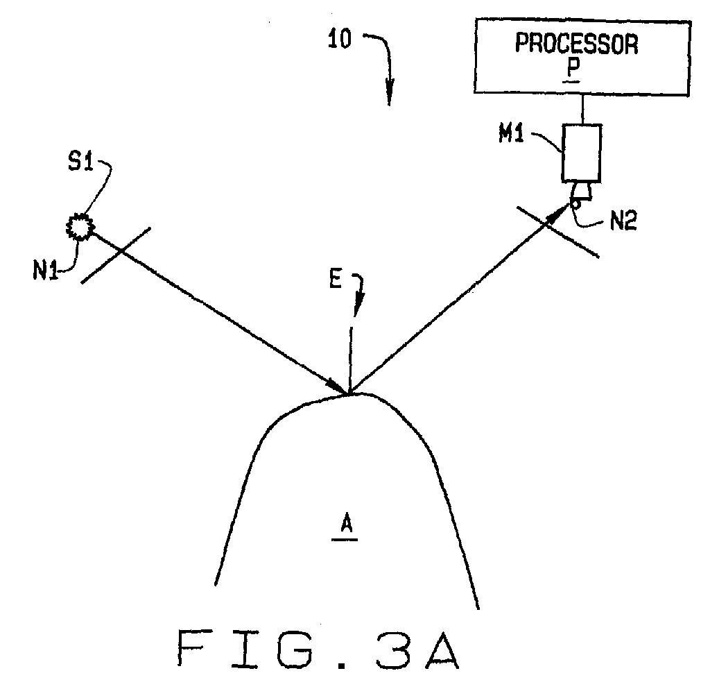
- apparatus for determining the leading edge E of an object such as airfoil A is indicated generally 10 in Figs. 3A and 3B.
- the apparatus comprises a first light source S1 shown in Fig. 3A as illuminating a portion of the airfoil including its leading edge.
- a first imaging means M1 obtains an image of a portion of the airfoil illuminated by light source S1.
- a second light source S2 is shown in Fig. 3B as illuminating another portion of the airfoil, also including the leading edge of the airfoil.
- a second imaging means M2 obtains an image of the portion of the airfoil illuminated by light source S2.
- the respective light sources S1 and S2 are spaced apart from each other, as are the respective imaging means M1 and M2.
- light source S1 and imaging means M2 are co-located in space. That is, their positions are coincident (or as nearly so as practical). This is as shown in Figs. 2A and 2B, where both light source S1 and imaging means M2 are located at the same position N1 in space.
- light source S2 and imaging means M1 are also co-located (coincident) in space.
- both light source S2 and imaging means M1 are located at a position N2.
- the respective imaging means which are cameras operating in the visible portion of the light spectrum, and their co-located light sources, can be conveniently installed or mounted in a common fixture (not shown). This has the advantage of allowing both the camera and light source to be conveniently moved from one location to another during the setup and calibration of the test equipment.
- Each camera M1, M2 is connected to a processing means P which comprises an image processor.
- the respective images obtained from the imaging means are processed by processor P to reconstruct (locate) leading edge E of the airfoil.
- processor P utilizes similarities in illumination of airfoil A by light sources S1 and S2 and the occlusion boundaries of the respective illuminated portions of the airfoil to locate its leading edge
- co-location of light source S2 and camera M1 and light source S1 and camera M2 produces corresponding angles of incidence and reflection in light transmitted by the respective light sources and received by their associated imaging means, and substantially identical regions of mutual illumination and observation.
- a reconstructed leading edge position PE3 is both on the outer surface of the airfoil, and substantially at the actual location of the leading edge at that point along the length of the airfoil.
- Figs. 4A-4C the effect of co-location of cameras and light sources in accordance with the present invention is shown with respect to the angle of incidence of the light emitted by the respective sources and received by the respective cameras. Since there are now common locations for both the light sources and camera, there is substantially no difference (i.e., bias) between one light source and its associated camera and the other light source and its associated camera. That is, the angles of incidence and reflection of the light transmitted between the sources and their associated cameras are essentially the same.
- Figs. 5A-5C the effect of the apparatus and method of the present invention on eliminating occlusion effects is shown.
- a region of mutual illumination and observation produced with light source S1 and imaging means M1 is indicated 13.
- a similar region I4 is shown to be produced with use of light source S2 and imaging means M2.
- the two regions 13 and 14 are compared to each other, they are shown to be substantially identical. This is important because these identical regions of mutual illumination and observation minimize reconstruction errors when the respective images are processed by processor P to calculate the leading edge location PE3 shown in Fig. 4C.
Landscapes
- Physics & Mathematics (AREA)
- General Physics & Mathematics (AREA)
- Length Measuring Devices By Optical Means (AREA)
Abstract
Description
Claims (11)
- Apparatus (10) for locating the leading edge (E) of an object (A) comprising:a first light source (S1) illuminating a portion of the object including its leading edge;a first imaging means (M1) obtaining an image of the portion of the object illuminated by the first light source;a second light source (S2) spaced apart from the first light source and also illuminating a portion of the object including its leading edge;a second imaging means (M2) spaced apart from the first imaging means and obtaining an image of a portion of the object including its leading edge; and,processing means (P) processing the respective images obtained by the first and second imaging means to reconstruct the leading edge of the object and establish its location.
- The apparatus of claim 1 wherein the position of the first light source (S1) and the second imaging means (M2) are co-located in space so to be coincident with each other as is the position of the second light source (S2) and the first imaging means (M1), thereby for the processing means (P) to utilize similarities in illumination of the object by the respective light sources and regions of mutual illumination and observation of the object to reconstruct the leading edge (E) of the object (A).
- The apparatus of claim 2 in which co-location of the first light source (S1) and the second imaging means (M2) and co-location of the second light source (S2) and the first imaging means (M1) provides corresponding angles of incidence and reflection in light transmitted by the respective light sources and received by their associated imaging means, and substantially identical regions of mutual illumination and observation, thereby to eliminate bias and minimize reconstruction errors by the processing means.
- The apparatus of claim 1 in which the first and second imaging means (M1,M2) each comprise cameras operating in the visible portion of the light spectrum.
- Apparatus (10) for determining the leading edge (E) of an object (A) comprising:a first light source (S1) illuminating a portion of the object including its leading edge;a first imaging means (M1) for obtaining an image of the portion of the object illuminated by the first light source;a second light source (S2) spaced apart from the first light source and also illuminating a portion of the object including its leading edge, the second light source and the first imaging means being co-located in space coincident with each other;a second imaging means (M2) spaced apart from the first imaging means for obtaining an image of a portion of the object including its leading edge, the first light source and second imaging means also being co-located in space coincident with each other; and,processing means (P) processing the respective images obtained from the first and second imaging means to reconstruct the leading edge of the object, the processing means utilizing similarities in illumination of the object by the respective light sources and occlusion boundaries of the respective illuminated portions of the object to reconstruct the leading edge, co-location of the first light source and the second imaging means and co-location of the second light source and the first imaging means producing corresponding angles of incidence and reflection in light transmitted by the respective light sources and received by their associated imaging means, and substantially identical regions of mutual illumination and observation, thereby to eliminate bias and minimize errors by the processing means in reconstructing the leading edge of the object.
- The apparatus of claim 5 in which the first and second imaging means (M1,M2) are cameras operating in the visible portion of the light spectrum.
- A method of locating the leading edge (E) of an object (A) comprising:separately illuminating the object with a first light source (S1) and a second light source (S2), the two light sources being spaced apart from each other, and the respective light sources illuminating respective portions of the object with each illuminated portion including the leading edge of the object;obtaining an image of the portion of the object illuminated by the first light source with a first imaging means (M1), and obtaining an image of the portion of the object illuminated by the second light source with a second imaging means (M2); and,processing the respective images to locate the leading edge of the object.
- The method of claim 7 in which processing the respective images to locate the leading edge of the object includes utilizing similarities in illumination of the object by the respective light sources, and occlusion boundaries of the respective illuminated portions of the object.
- The method of claim 8 in which the first light source (S1) and the second imaging means (M2) are co-located in space so to be coincident with each other, and in which the second light source (S2) and the first imaging means (M1) are also co-located in space so to be coincident with each other, co-location of the first light source and the second imaging means and co-location of the second light source and the first imaging means producing corresponding angles of incidence and reflection in light transmitted by the respective light sources and received by their associated imaging means, and substantially identical regions of mutual illumination and observation, thereby to eliminate bias and minimize errors in the processing of the images of the object and the reconstruction of the leading edge of the object.
- The method of claim 7 in which the respective imaging means (M1,M2) comprise cameras operating in the visible portion of the light spectrum.
- A method of locating the leading edge (E) of an object (A) comprising:separately illuminating the object with a first light source (S1) and a second light source (S2), the two light sources being spaced apart from each other, and the respective light sources illuminating respective portions of the object with each illuminated portion including the leading edge of the object;obtaining an image of the portion of the object illuminated by the first light source with a first imaging means (M1), and obtaining an image of the portion of the object illuminated by the second light source with a second imaging means (M2);co-locating the first light source and the second imaging means at a coincident point (N1) in space, and co-locating of the second light source and the first imaging means at another coincident point (N2) in space; and,processing the respective images to reconstruct the leading edge of the object, co-location of the first light source and the second imaging means and co-location of the second light source and the first imaging means producing corresponding angles of incidence and reflection in light transmitted by the respective light sources and received by their associated imaging means, and substantially identical regions of mutual illumination and observation, thereby to eliminate bias and minimize errors in the processing of the images of the object and the reconstruction of the leading edge of the object.
Applications Claiming Priority (2)
| Application Number | Priority Date | Filing Date | Title |
|---|---|---|---|
| US10/063,228 US6876459B2 (en) | 2002-04-01 | 2002-04-01 | Method and apparatus for optical measurement of the leading edge position of an airfoil |
| US63228 | 2002-04-01 |
Publications (2)
| Publication Number | Publication Date |
|---|---|
| EP1351034A2 true EP1351034A2 (en) | 2003-10-08 |
| EP1351034A3 EP1351034A3 (en) | 2003-11-26 |
Family
ID=28038718
Family Applications (1)
| Application Number | Title | Priority Date | Filing Date |
|---|---|---|---|
| EP03252065A Withdrawn EP1351034A3 (en) | 2002-04-01 | 2003-04-01 | Method and apparatus for optical measurement of the leading edge position of an airfoil |
Country Status (3)
| Country | Link |
|---|---|
| US (1) | US6876459B2 (en) |
| EP (1) | EP1351034A3 (en) |
| JP (1) | JP2003329410A (en) |
Cited By (1)
| Publication number | Priority date | Publication date | Assignee | Title |
|---|---|---|---|---|
| EP1777491A1 (en) * | 2005-10-24 | 2007-04-25 | General Electric Company | Method and apparatus for inspecting an object |
Families Citing this family (4)
| Publication number | Priority date | Publication date | Assignee | Title |
|---|---|---|---|---|
| US7327857B2 (en) * | 2004-03-09 | 2008-02-05 | General Electric Company | Non-contact measurement method and apparatus |
| US7289227B2 (en) * | 2004-10-01 | 2007-10-30 | Nomos Corporation | System and tracker for tracking an object, and related methods |
| FR2963093B1 (en) * | 2010-07-26 | 2012-08-03 | Vit | INSTALLATION OF 3D OPTICAL INSPECTION OF ELECTRONIC CIRCUITS |
| US10295436B2 (en) * | 2016-03-17 | 2019-05-21 | Honeywell International Inc. | Structured light measuring apparatus and methods |
Family Cites Families (7)
| Publication number | Priority date | Publication date | Assignee | Title |
|---|---|---|---|---|
| US4872757A (en) * | 1988-04-20 | 1989-10-10 | Ball Corporation | Optical convex surface profiling and gauging apparatus and method therefor |
| US5159361A (en) * | 1989-03-09 | 1992-10-27 | Par Technology Corporation | Method and apparatus for obtaining the topography of an object |
| DE4131365C2 (en) * | 1991-09-20 | 1994-02-10 | Erhardt & Leimer Gmbh | Device for detecting the position of an edge produced by a jump in the thickness of the goods on a running web |
| US5867250A (en) * | 1996-05-03 | 1999-02-02 | Baron; William S. | Apparatus and method for optically mapping front and back surface topographies of an object |
| US6175415B1 (en) * | 1997-02-19 | 2001-01-16 | United Technologies Corporation | Optical profile sensor |
| ATE292784T1 (en) * | 1999-04-30 | 2005-04-15 | Christoph Dr Wagner | METHOD FOR OPTICAL FORM DETECTION OF OBJECTS |
| ITVE20000023A1 (en) * | 2000-05-12 | 2001-11-12 | Tecnogamma S A S Di Zanin E & | LASER EQUIPMENT FOR THE CONTROL OF THE RAILWAYS OF A RAILWAY LINE. |
-
2002
- 2002-04-01 US US10/063,228 patent/US6876459B2/en not_active Expired - Lifetime
-
2003
- 2003-04-01 EP EP03252065A patent/EP1351034A3/en not_active Withdrawn
- 2003-04-01 JP JP2003097534A patent/JP2003329410A/en active Pending
Cited By (2)
| Publication number | Priority date | Publication date | Assignee | Title |
|---|---|---|---|---|
| EP1777491A1 (en) * | 2005-10-24 | 2007-04-25 | General Electric Company | Method and apparatus for inspecting an object |
| US7898651B2 (en) | 2005-10-24 | 2011-03-01 | General Electric Company | Methods and apparatus for inspecting an object |
Also Published As
| Publication number | Publication date |
|---|---|
| US6876459B2 (en) | 2005-04-05 |
| EP1351034A3 (en) | 2003-11-26 |
| US20030184767A1 (en) | 2003-10-02 |
| JP2003329410A (en) | 2003-11-19 |
Similar Documents
| Publication | Publication Date | Title |
|---|---|---|
| US7327857B2 (en) | Non-contact measurement method and apparatus | |
| US6678057B2 (en) | Method and device for reduction in noise in images from shiny parts | |
| US6795200B1 (en) | Method and system for dimensioning boxes or other cuboid objects | |
| US6868194B2 (en) | Method for the extraction of image features caused by structure light using image reconstruction | |
| US10462444B2 (en) | Three-dimensional inspection | |
| JP2010071782A (en) | Three-dimensional measurement apparatus and method thereof | |
| US6985238B2 (en) | Non-contact measurement system for large airfoils | |
| JPH11183134A (en) | Method for measuring interval and displacement amount between facing parts | |
| CN110621957A (en) | Method for referencing a plurality of sensor units and associated measuring device | |
| US7782453B2 (en) | Method for measuring missing corner dimensions | |
| CN111412868A (en) | Surface roughness measurement | |
| US12553833B2 (en) | Visual inspection apparatus and visual inspection method | |
| TWI428569B (en) | Ranging method, ranging system and processing software | |
| US6876459B2 (en) | Method and apparatus for optical measurement of the leading edge position of an airfoil | |
| CN100419375C (en) | 3D Edge Localization Method with Side Illumination | |
| US20030113020A1 (en) | Method for the extraction of image features caused by structure light using template information | |
| US10715790B2 (en) | System and method for lead foot angle inspection using multiview stereo vision | |
| TWI428568B (en) | Distance measurement method and system, and processing software thereof | |
| CN113227707B (en) | Three-dimensional shape measuring device, three-dimensional shape measuring method, and storage medium | |
| KR102063568B1 (en) | Apparatus for measuring sub-aperture surface profile | |
| US20040047517A1 (en) | Shadow-free 3D and 2D measurement system and method | |
| US6969836B2 (en) | Space carving for measurement of high-curvature areas on a mechanical part | |
| JPH0755440A (en) | Shape recognition device | |
| Munaro et al. | Fast 2.5 D model reconstruction of assembled parts with high occlusion for completeness inspection |
Legal Events
| Date | Code | Title | Description |
|---|---|---|---|
| PUAI | Public reference made under article 153(3) epc to a published international application that has entered the european phase |
Free format text: ORIGINAL CODE: 0009012 |
|
| AK | Designated contracting states |
Kind code of ref document: A2 Designated state(s): AT BE BG CH CY CZ DE DK EE ES FI FR GB GR HU IE IT LI LU MC NL PT RO SE SI SK TR |
|
| AX | Request for extension of the european patent |
Extension state: AL LT LV MK |
|
| PUAL | Search report despatched |
Free format text: ORIGINAL CODE: 0009013 |
|
| AK | Designated contracting states |
Kind code of ref document: A3 Designated state(s): AT BE BG CH CY CZ DE DK EE ES FI FR GB GR HU IE IT LI LU MC NL PT RO SE SI SK TR |
|
| AX | Request for extension of the european patent |
Extension state: AL LT LV MK |
|
| RIC1 | Information provided on ipc code assigned before grant |
Ipc: 7G 01B 11/02 B Ipc: 7G 01B 11/24 A |
|
| 17P | Request for examination filed |
Effective date: 20040526 |
|
| AKX | Designation fees paid |
Designated state(s): DE FR GB IT |
|
| 17Q | First examination report despatched |
Effective date: 20040902 |
|
| STAA | Information on the status of an ep patent application or granted ep patent |
Free format text: STATUS: THE APPLICATION IS DEEMED TO BE WITHDRAWN |
|
| 18D | Application deemed to be withdrawn |
Effective date: 20091102 |