EP1351015A2 - Light projector - Google Patents
Light projector Download PDFInfo
- Publication number
- EP1351015A2 EP1351015A2 EP03006946A EP03006946A EP1351015A2 EP 1351015 A2 EP1351015 A2 EP 1351015A2 EP 03006946 A EP03006946 A EP 03006946A EP 03006946 A EP03006946 A EP 03006946A EP 1351015 A2 EP1351015 A2 EP 1351015A2
- Authority
- EP
- European Patent Office
- Prior art keywords
- polarized light
- light
- vertical
- irradiated
- polarized
- Prior art date
- Legal status (The legal status is an assumption and is not a legal conclusion. Google has not performed a legal analysis and makes no representation as to the accuracy of the status listed.)
- Granted
Links
Images





Classifications
-
- F—MECHANICAL ENGINEERING; LIGHTING; HEATING; WEAPONS; BLASTING
- F21—LIGHTING
- F21S—NON-PORTABLE LIGHTING DEVICES; SYSTEMS THEREOF; VEHICLE LIGHTING DEVICES SPECIALLY ADAPTED FOR VEHICLE EXTERIORS
- F21S41/00—Illuminating devices specially adapted for vehicle exteriors, e.g. headlamps
- F21S41/60—Illuminating devices specially adapted for vehicle exteriors, e.g. headlamps characterised by a variable light distribution
- F21S41/63—Illuminating devices specially adapted for vehicle exteriors, e.g. headlamps characterised by a variable light distribution by acting on refractors, filters or transparent cover plates
-
- F—MECHANICAL ENGINEERING; LIGHTING; HEATING; WEAPONS; BLASTING
- F21—LIGHTING
- F21V—FUNCTIONAL FEATURES OR DETAILS OF LIGHTING DEVICES OR SYSTEMS THEREOF; STRUCTURAL COMBINATIONS OF LIGHTING DEVICES WITH OTHER ARTICLES, NOT OTHERWISE PROVIDED FOR
- F21V9/00—Elements for modifying spectral properties, polarisation or intensity of the light emitted, e.g. filters
- F21V9/14—Elements for modifying spectral properties, polarisation or intensity of the light emitted, e.g. filters for producing polarised light
-
- F—MECHANICAL ENGINEERING; LIGHTING; HEATING; WEAPONS; BLASTING
- F21—LIGHTING
- F21S—NON-PORTABLE LIGHTING DEVICES; SYSTEMS THEREOF; VEHICLE LIGHTING DEVICES SPECIALLY ADAPTED FOR VEHICLE EXTERIORS
- F21S41/00—Illuminating devices specially adapted for vehicle exteriors, e.g. headlamps
- F21S41/10—Illuminating devices specially adapted for vehicle exteriors, e.g. headlamps characterised by the light source
- F21S41/12—Illuminating devices specially adapted for vehicle exteriors, e.g. headlamps characterised by the light source characterised by the type of emitted light
- F21S41/135—Polarised
-
- F—MECHANICAL ENGINEERING; LIGHTING; HEATING; WEAPONS; BLASTING
- F21—LIGHTING
- F21V—FUNCTIONAL FEATURES OR DETAILS OF LIGHTING DEVICES OR SYSTEMS THEREOF; STRUCTURAL COMBINATIONS OF LIGHTING DEVICES WITH OTHER ARTICLES, NOT OTHERWISE PROVIDED FOR
- F21V9/00—Elements for modifying spectral properties, polarisation or intensity of the light emitted, e.g. filters
- F21V9/40—Elements for modifying spectral properties, polarisation or intensity of the light emitted, e.g. filters with provision for controlling spectral properties, e.g. colour, or intensity
-
- F—MECHANICAL ENGINEERING; LIGHTING; HEATING; WEAPONS; BLASTING
- F21—LIGHTING
- F21W—INDEXING SCHEME ASSOCIATED WITH SUBCLASSES F21K, F21L, F21S and F21V, RELATING TO USES OR APPLICATIONS OF LIGHTING DEVICES OR SYSTEMS
- F21W2102/00—Exterior vehicle lighting devices for illuminating purposes
Definitions
- This invention relates to a light projector such as a headlight for use with a vehicle.
- the headlight for use with a vehicle is operated to light up under circumstances where a driver recognizes difficulty in seeing an area ahead of the vehicle with the unaided eye.
- the headlight is typically used in the nighttime, in a downpour of rain, in fog, or in other similar conditions. Actually, in some instances where the headlight is lit in a downpour of rain or in fog, an irradiated light beam diffuses by reflecting off raindrops and fine particles of water vapor, and the driver's view is obstructed by, as it were, a light wall standing in front of the vehicle.
- JP 61-253236 A A technique utilizing polarization for a headlight of a vehicle is disclosed in JP 61-253236 A.
- the invention as disclosed in this publication is directed to a technique for preventing a headlight providing a high beam from dazzling a driver.
- two polarizing filters are provided: one is provided in an optical path of the headlight for irradiating a high beam, and the other is stuck on a windshield, so that a polarization axis of the latter is perpendicular to that of the former. Accordingly, the high beam is cut off using the two polarizing filters (one on the windshield of the driver's vehicle, and the other in the headlight of oncoming vehicles), and the driver can thereby be prevented from being dazzled.
- Another exemplified and more specific object of the present invention is to provide a light projector that has high efficiency in utilization of light irradiated from a headlight, and in high heat resistance, and that can ensure considerably increased forward visibility under conditions which would restrict the visibility.
- a light projector includes a light source, and a polarized light splitter that splits a beam of unpolarized light irradiated from the light source into p-polarized light and s-polarized light, and the p-polarized light and/or the s-polarized light are irradiated as vertical polarized light having electric field plane of vibration substantially vertical to level ground, and/or as horizontal polarized light having electric field plane of vibration substantially parallel to the level ground.
- a beam of light irradiated from the light source is split into p-polarized light and s-polarized light, and then the p-polarized light and/or the s-polarized light are utilized as vertical polarized light having electric field plane of vibration substantially vertical to level ground and/or horizontal polarized light having electric field plane of vibration substantially parallel to the level ground; therefore, considerably increased forward visibility can be ensured under conditions which would restrict the visibility while keeping high efficiency in utilization of light and high heat resistance.
- the p-polarized light and the s-polarized light are defined in relation to the polarized light splitter; the p-polarized light has a direction of vibration of the electric field parallel to a plane of incidence of the polarized light splitter, while the s-polarized light has a direction of vibration of the electric field perpendicular to the plane of incidence of the polarized light splitter.
- the plane of incidence is, as shown in FIG. 1, a plane containing the normal at the point where incident light strikes a reflecting surface, and an optical axis of the incident light.
- the vertical polarized light and the horizontal polarized light are defined in relation to the direction of vibration of the electric field of the polarized light with respect to the ground to which light is irradiated. It is thus to be understood that the vertical polarized light and the horizontal polarized light are the concepts distinct from the p-polarized light and the s-polarized light as described above.
- Light having a direction of vibration of the electric field substantially vertical to the level ground (reflecting surface) is herein termed vertical polarized light
- light having a direction of vibration of the electric field substantially parallel to the level ground (reflecting surface) is herein termed horizontal polarized light.
- the vertical polarized light adequately refers to polarized light having a direction of vibration of the electric field substantially parallel to a plane of incidence of light which strikes the ground
- the horizontal polarized light adequately refers to polarized light having a direction of vibration of the electric field substantially vertical to the plane of incidence of light which strikes the ground.
- FIG. 2A shows directions of vibration of p-polarized light and s-polarized light split by the polarized light splitter which is placed in an orientation as illustrated therein with respect to the ground.
- the p-polarized light that has been split off becomes vertical polarized light having a direction of vibration vertical ( i.e ., perpendicular to the ground), and the s-polarized light that has been split off becomes horizontal polarized light having a direction of vibration horizontal ( i.e ., parallel to the ground).
- FIG. 2B shows directions of vibration of p-polarized light and s-polarized light split by the polarized light splitter which is placed in an orientation tilted with respect to the ground.
- the polarized light splitter tilts with respect to the ground; therefore, the s-polarized light is not identical with the horizontal polarized light, and the p-polarized light is not identical with the vertical polarized light.
- one of the p-polarized light and the s-polarized light is irradiated farther from the light source as the vertical polarized light, and the other of the p-polarized light and the s-polarized light is irradiated to an area nearer to the light source as the horizontal polarized light.
- the p-polarized light having a direction of vibration parallel to the plane of incidence exhibits lower reflectance than that of the s-polarized light having a direction of vibration vertical to the plane of incidence.
- the vertical polarized light if incident on top or under surfaces of raindrops, or the level ground, as reflecting surfaces, have a direction of vibration parallel to the plane of incidence; thus, the reflectance of the vertical polarized light which strikes the raindrops or a film of water on the surface of the road and reflects in a vertical direction is lower than that of the horizontal vertical polarized light, as is the above-described case with the p-polarized light.
- Reflection on the raindrops or the surface of the road which could impair visibility is mainly derived from light reflected and diffused in a direction vertical to the ground.
- the light projector according to this aspect of the present invention can maintain better forward visibility in comparison with any conventional light projectors that irradiate unpolarized light.
- irradiation of the horizontal polarized light toward areas nearer to the light source makes it possible to ensure visibility of areas around the light source, and to enhance efficiency in utilization of light irradiated from the light source.
- one of the p-polarized light and the s-polarized light is irradiated as first vertical polarized light, and the other of the p-polarized light and the s-polarized light is changed into second vertical polarized light utilizing a phase changer and irradiated as the second vertical polarized light.
- the p-polarized light and s-polarized light that has been split by the polarized light splitter are both irradiated forward as the vertical polarized light, and such arrangement makes it possible to restrict vertically diffusing reflection, which would be caused by raindrops, fine particles of water vapor, a film of water on the surface of the road generated in a downpour of rain or in heavy fog, and would thus impair visibility. Consequently, the light projector according to this aspect of the present invention can maintain better forward visibility under the bad conditions as above, in comparison with any conventional light projectors that irradiate unpolarized light.
- the phase changer may be a 1/2 wavelength retardation plate.
- the use of the 1/2 wavelength retardation plate for the phase changer allows the light projector to change the s-polarized light or p-polarized light to vertical polarized light efficiently with almost no loss of the amount of light.
- the polarized light splitter may be made of material which is birefringent.
- the use of a birefringent material as the polarized light splitter allows the light projector to efficiently split unpolarized light into s-polarized light and p-polarized light.
- the above-described light projector according to the present invention may be used for a headlight for a vehicle.
- the vehicle that adopts the light projector as headlights thereof can reliably provide the driver with better forward visibility under tough conditions (e.g ., in heavy fog, or in a downpour of rain) in comparison with any conventional headlights.
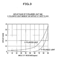
- the ordinates represent reflectance, and the abscissas represent angles of incidence of a light beam where the angle formed with the normal of the surface (reflecting surface) of the glass material is zero degrees.
- the p-polarized light as herein referred to has a direction of vibration of the electric field parallel to the plane of incidence, and corresponds to the vertical polarized light as defined in relation to the present invention which has a direction of vibration vertical with respect to the ground upon reflecting a surface parallel to the ground ( see FIG. 1).
- the s-polarized light has a direction of vibration of the electric field vertical to the plane of incidence, and corresponds to the horizontal polarized light as defined in relation to the present invention which has a direction of vibration horizontal with respect to the ground upon reflecting a surface parallel to the ground (see also FIG. 1).
- the reflectance of the s-polarized light is greater than the reflectance of the p-polarized light (vertical polarized light), with the exception of cases where the angle of incidence is 0 degrees or 90 degrees.
- the angle of incidence ranges between 20 degrees and 80 degrees
- the reflectance of the s-polarized light is more than twice as great as the reflectance of the p-polarized light (vertical polarized light).
- irradiated light when a headlight of a vehicle is lit up in heavy fog or in a downpour of rain, irradiated light sometimes produces a phenomenon that seems as if a light wall emerges in front of the vehicle, so that the driver cannot sufficiently be provided with good forward visibility in some instances.
- the light irradiated from the headlight diffuses by reflecting off raindrops or fine particles of water vapor, and especially because the light diffusively reflects mainly in directions substantially vertical to the ground.
- FIG. 4 Shown in FIG. 4 are shapes of water droplets flying from the air in heavy fog or in a downpour of rain.
- Each water droplet is substantially spherical in shape, but the larger a particle diameter thereof, the more oblate the water droplet is made by air resistance given during falling, and a superficies thereof increases accordingly.
- the water droplet as thus shaped, makes the light irradiated from the headlight and incident thereon from a sideward direction diffuse in every direction, particularly so as to diffusively reflect in a direction substantially vertical to the ground.
- the light once diffusively reflecting off the water droplets reflects off a great number of water droplets that exist in the neighborhood again and again, and an entire area irradiated by the light of the headlight illuminates, and makes the driver feel as if a light wall emerges near around the vehicle.
- light reflecting in directions vertical to the ground obstructs the driver's view, so that the driver can hardly see a distant place.
- Distribution of light irradiated from the headlight under the conditions as described above is schematically shown in FIG. 5A.
- the light irradiated from the headlight randomly diffuses by reflecting off the surfaces of raindrops or fine particles of water vapor which exist on passages of the light, and forms a light wall near around the vehicle, making it difficult for the driver to get the visibility of areas far from the vehicle.
- FIG. 5B is a schematic illustration of diffusion of light taking place by reflecting off the surfaces of raindrops when the light is irradiated from a headlight. As shown in FIG. 5B, the light repeatedly reflects on the surfaces of raindrops in a variety of directions, and gives an visual image as if a light wall emerges in front of the vehicle. Under the circumstances, the driver cannot see an object that could be seen under a normal condition.
- the light irradiated from the headlight may be converted into vertical polarized light.
- This allows vertically diffusive reflection of light to be considerably reduced in comparison with the case in which unpolarized light is irradiated, because the reflectance of the vertical polarized light in a direction vertical to the ground is less than that of the horizontal polarized light.
- the above means serves to restrict the reflected light from diffusing in a vertical direction, and thus serves to prevent a light wall from being formed. Therefore, the driver's view is not obstructed, so that the driver can be reliably provided with good forward visibility.
- FIG. 6 is a schematic diagram showing one exemplified embodiment of a light projector according to the present invention.
- light irradiated from a light source is split into p-polarized light and s-polarized light, so that the p-polarized light is irradiated as first vertical polarized light, and further the s-polarized light formed by splitting the unpolarized light is changed into second vertical polarized light utilizing a phase changer and irradiated as the second vertical polarized light; consequently, the light projector irradiates the first and second vertical polarized light forward of a vehicle.
- the light projector includes a light source 1, a collimating lens 2 for making light (unpolarized light) irradiated from the light source 1 into parallel beams of light by making angles of irradiation in alignment with one another, a polarized light beam splitter 3 for splitting the beams of light from the collimating lens 2 into p-polarized light (first vertical polarized light) and s-polarized light (horizontal polarized light), a reflector 4 for reflecting the s-polarized light (horizontal polarized light) generated by splitting the collimated beams of light utilizing the polarized light beam splitter 3, and a 1/2 wavelength retardation plate (or sheet) 6 for changing the s-polarized light (horizontal polarized light) into second vertical polarized light, with lenses 5a, 5b used for irradiating forward light irradiated from the light projector.
- polarized light splitter and “phase changer” used for describing the present invention correspond to the polarized light beam splitter 3 and the 1/2 wavelength retardation plate 6, respectively.
- a collimating lens is used to make light irradiated from the light source into parallel beams, but a concave mirror such as a parabolic reflector may be used instead.
- Light unpolarized light irradiated from an HID (high intensity discharge) light or other light source (light source 1) is converted into parallel beams using the collimating lens 2, and strikes on the polarized light beam splitter 3.
- P-polarized light formed herein does not reflect in the polarized light beam splitter 3 but passes through the polarized light beam splitter 3, to reach the lens 5, and is irradiated forward of the vehicle as first vertical polarized light.
- s-polarized light reflects and changes a traveling direction thereof in the polarized light beam splitter 3, to reach the reflector 4, in which an irradiating direction thereof is adjusted; the s-polarized light is then changed in direction of polarization upon passing through the 1/2 wavelength retardation plate 6, and made into second vertical polarized light, passing through the lens 5b to be irradiated forward of the vehicle.
- the 1/2 wavelength retardation plate 6 is disposed in an orientation that tilts at 45 degrees toward a direction allowing the direction of polarization to change with respect to the optical axis so that the direction of polarization changes by an angle of 90 degrees.
- light irradiated from the light source 1 is split up into p-polarized light and s-polarized light; the p-polarized light is set to be first vertical polarized light, and the s-polarized light is converted into second vertical polarized light, so that only the vertical polarized light having lower reflectance in a direction vertical to the ground is irradiated forward of the vehicle. Therefore, even in a downpour of rain or in heavy fog, diffusive reflection of the light in the vertical direction, which would be caused by raindrops or fine particles of water vapor, can be restricted, whereby better forward visibility as compared with conventional light projectors can be ensured.
- FIG. 7A is a schematic diagram showing distribution of light irradiated from a headlight as results when the light projector according to the present invention is lit up in heavy fog or in a downpour of rain.
- Vertical polarized light irradiated from the headlight of the present invention is far less likely to diffusively reflect in a vertical direction in comparison with conventional headlights that irradiate unpolarized light even if either light strikes on raindrops or fine particles of water vapor alike. Accordingly, a light wall, so called, does not emerge in front of the vehicle, and thus the driver can be securely provided with good forward visibility.
- FIG. 7A is a schematic diagram showing distribution of light irradiated from a headlight as results when the light projector according to the present invention is lit up in heavy fog or in a downpour of rain.
- Vertical polarized light irradiated from the headlight of the present invention is far less likely to diffusively reflect in a vertical direction in comparison with conventional headlights that irradiate unpolar
- FIG. 7B is a schematic diagram showing diffusion of light which takes place on the surfaces of raindrops as a result of reflection of the light beams irradiated from the light projector according to the present invention. Irradiation of vertical polarized light as in the present invention reduces the likelihood of vertically diffusing reflection that could take place on the surfaces of raindrops, allowing the driver to secure adequate forward visibility without obstruction of the light wall.
- the light projector according to the present invention uses the 1/2 wavelength retardation plate 6 to change the s-polarized light, which has been produced by splitting up unpolarized light utilizing the polarized light beam splitter 3, into the second vertical polarized light, and thus light irradiated from the light source 1 can be utilized efficiently.
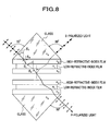
- the polarized light beam splitter 3 as used herein may be implemented by alternately laminating low-refractive-index films and high-refractive-index films between opposite surfaces of a pair of glass prisms, as shown in FIG. 8.
- the polarized light beam splitter 3 makes good use of a phenomenon in which incident light striking on a medium at a polarizing angle (Brewster's angle) makes the reflectance of p-polarized light zero and allows only s-polarized light to reflect.
- the reflectance and thickness of each film are appropriately designed so that the incident light strikes on the surface of the multilayered films at the polarizing angle.
- the use of the beam splitter 3 having the above structure makes it possible to split up the incident light to obtain p-polarized light and s-polarized light separately.
- n G 2 n H 2 n L 2 /( n L 2 + n H 2 )
- n H is the index of refraction of high-refractive-index films
- n L is the index of refraction of low-refractive-index films
- n G is the index of refraction of glass.
- the glass prism made of glass having the index of refraction ( n G ) of 1.62 may be used.
- a device that utilizes a birefringent material to split a light beam into p-polarized light and s-polarized light may be adopted as the polarized light beam splitter 3.
- the light beam can be split into two components; i.e ., a p-polarized light component and an s-polarized light component, different from each other in propagation velocity at which each component is transmitted through a crystal of the material, so that the p-polarized light and the s-polarized light can be obtained separately.
- materials usable as the birefringent material are, for example, Calcite (CaCO 3 ) and the like. That is, the polarized light beam splitter 3 made of calcite crystal can be used to obtain p-polarized light and s-polarized light separately.
- the light projector according to the present invention splits light irradiated from a light source into p-polarized light and s-polarized light, changes the s-polarized light into vertical polarized light and irradiates the vertical polarized light forward of the vehicle; thus, there should inevitably arise small losses of the amount of light in each of the steps (of splitting light into s-polarized light and p-polarized light, and changing the s-polarized light into vertical polarized light).
- the light projector according to the present invention holds promise of resulting improvement in forward visibility under unfavorable conditions to such an extent as to more than offset the undesired losses.
- the light source 1 used herein is not limited to an HID lamp, but a lamp using a filament may be employed as usual.
- the s-polarized light obtained by splitting unpolarized light using the polarized light beam splitter 3 is changed into second vertical polarized light using the 1/2 wavelength retardation plate 6, and irradiated forward of the vehicle together with first vertical polarized light, but a light projector in which the 1/2 wavelength retardation plate 6 is not employed can also be conceived.
- FIG. 9 another exemplified embodiment of the light projector according to the present invention as shown in FIG. 9 has the same construction as the light projector as shown in FIG. 6, except that no 1/2 wavelength retardation plate 6 is provided.
- the s-polarized light obtained by splitting unpolarized light using the polarized light beam splitter 3 is not changed into vertical polarized light, but irradiated to an area near the vehicle as horizontal polarized light.
- the vertical horizontal light based upon the p-polarized light is irradiated to an area farther from the vehicle, and thus improved visibility in a far area can be ensured even under unfavorable conditions.
- the light projector according to the present invention is exemplarily applied to a headlight such as a fog lamp in the above embodiments
- the embodiments of the present invention are not limited thereto; i.e ., any other light projectors such as a rear fog lamp, a tail lamp, a stop lamp, a back lamp, etc. can be implemented according to the present invention.
- the use of the light projector according to the present invention for the lamps as recited above in a vehicle enables a driver of another vehicle that follows to easily recognize the presence of the vehicle ahead of his/her own vehicle, even under tough conditions that would restrict forward visibility to an inadequate level (e.g ., in a downpour of rain, in heavy fog, etc.), because light irradiated from the lamps is restricted from reflecting off raindrops or fine particles of water vapor.
- an inadequate level e.g ., in a downpour of rain, in heavy fog, etc.
- the light projector according to the present invention can be applied to a searchlight, a flashlight, an illuminating device in a lighthouse, or the like, as well.
- the light projector according to the present invention applied to various light projectors for use in consumer goods, military installations, for recreational use, for security purposes, or the like can also provide improved forward visibility as compared with conventional light projectors, in heavy fog, in rain, or in adverse conditions of various kinds, in a variety of situations.
- the present invention constructed as described above produces distinctive advantageous effects as follows.
- the light projector as one aspect of the present invention is designed to split light irradiated from a light source into p-polarized light and s-polarized light using a polarized light splitter, and to irradiate the p-polarized light and the s-polarized light as vertical polarized light having electric field plane of vibration substantially vertical to the ground, and/or as horizontal polarized light having electric field plane of vibration substantially parallel to the ground.
- This arrangement has high efficiency in utilization of light, and high heat resistance, and can provide considerably increased forward visibility under conditions which would restrict the visibility.
- the light projector as another aspect of the present invention is designed to irradiate vertical polarized light, which is low in reflectance of light in a direction vertical to the ground, to an area farther from the light source.
- This arrangement can contribute to reduced reflection of vertically diffusing light that would take place on surfaces of raindrops or fine particles of water vapor in a downpour of rain or in heavy fog.
- a headlight for a vehicle to which the present invention is applied can provide a driver with sufficient forward visibility even under such adverse conditions.
- the light projector is also designed to irradiate horizontal polarized light to an area nearer to the light source, and thus can utilize light irradiated from the light source efficiently, while ensuring the driver's view near the vehicle.
- the light projector as yet another aspect of the present invention is designed to split light irradiated from a light source into p-polarized light and s-polarized light, to irradiate one of the p-polarized light and the s-polarized light as first vertical polarized light, and to change the other of the p-polarized light and the s-polarized light into second vertical polarized light utilizing a phase changer such as a 1/2 wavelength retardation plate and irradiate the second vertical polarized light.
- This arrangement can increase the amount of light of the vertical polarized light, which is low in reflectance of light in a direction vertical to the ground, allowing a driver to be more reliably provided with forward visibility, in a case where this aspect of the present invention is applied to a headlight of a vehicle, for example.
- a birefringent material may be used for the above polarized light splitter, and if so, unpolarized light generated from the light source can efficiently be split up into s-polarized light and p-polarized light.
- the light projector according to the present invention may be used for a headlight of a vehicle, which serves to achieve considerably increased forward visibility of a driver in heavy fog or in a downpour of rain in comparison with a conventional headlight.
- a light projector includes a polarized light splitter 3 that splits unpolarized light irradiated from a light source 1 into p-polarized light and s-polarized light, and the p-polarized light and/or the s-polarized light are irradiated as vertical polarized light and/or horizontal polarized light, providing a driver with considerably improved forward visibility in comparison with a conventional headlight.
Landscapes
- Engineering & Computer Science (AREA)
- General Engineering & Computer Science (AREA)
- Physics & Mathematics (AREA)
- Spectroscopy & Molecular Physics (AREA)
- Non-Portable Lighting Devices Or Systems Thereof (AREA)
- Lighting Device Outwards From Vehicle And Optical Signal (AREA)
Abstract
Description
Claims (6)
- A light projector comprising:wherein the p-polarized light and/or the s-polarized light are irradiated as vertical polarized light having electric field plane of vibration substantially vertical to level ground, and/or as horizontal polarized light having electric field plane of vibration substantially parallel to the level ground.a light source; anda polarized light splitter that splits a beam of unpolarized light irradiated from the light source into p-polarized light and s-polarized light,
- A light projector according to claim 1, wherein one of the p-polarized light and the s-polarized light is irradiated to an area farther from the light source as the vertical polarized light, and the other of the p-polarized light and the s-polarized light is irradiated to an area nearer to the light source as the horizontal polarized light.
- A light projector according to claim 1, further comprising a phase changer, wherein one of the p-polarized light and the s-polarized light is irradiated as first vertical polarized light, and the other of the p-polarized light and the s-polarized light is changed into second vertical polarized light utilizing the phase changer and irradiated as the second vertical polarized light.
- A light projector according to claim 3, wherein the phase changer is a 1/2 wavelength retardation plate.
- A light projector according to any one of claims 1 through 4, wherein the polarized light splitter is made of material which is birefringent.
- A light project according to any one of claims 1 through 5, which is used for a headlight for a vehicle.
Applications Claiming Priority (2)
| Application Number | Priority Date | Filing Date | Title |
|---|---|---|---|
| JP2002104005A JP2003297116A (en) | 2002-04-05 | 2002-04-05 | Floodlight device |
| JP2002104005 | 2002-04-05 |
Publications (3)
| Publication Number | Publication Date |
|---|---|
| EP1351015A2 true EP1351015A2 (en) | 2003-10-08 |
| EP1351015A3 EP1351015A3 (en) | 2005-01-19 |
| EP1351015B1 EP1351015B1 (en) | 2007-04-25 |
Family
ID=28035961
Family Applications (1)
| Application Number | Title | Priority Date | Filing Date |
|---|---|---|---|
| EP03006946A Expired - Lifetime EP1351015B1 (en) | 2002-04-05 | 2003-03-26 | Light projector |
Country Status (7)
| Country | Link |
|---|---|
| US (1) | US7070308B2 (en) |
| EP (1) | EP1351015B1 (en) |
| JP (1) | JP2003297116A (en) |
| KR (1) | KR20030080200A (en) |
| CN (1) | CN1449950A (en) |
| CA (1) | CA2424131C (en) |
| DE (1) | DE60313389T2 (en) |
Cited By (10)
| Publication number | Priority date | Publication date | Assignee | Title |
|---|---|---|---|---|
| EP1437544A3 (en) * | 2003-01-07 | 2006-08-02 | HONDA MOTOR CO., Ltd. | Indicator for a vehicle with polarized light |
| WO2015063512A1 (en) * | 2013-11-04 | 2015-05-07 | Wells Simon Robert | Fog light systems |
| EP3021039A1 (en) * | 2014-11-13 | 2016-05-18 | LG Electronics Inc. | Headlights having one light source module for a high beam and a low beam |
| US9778475B2 (en) | 2014-11-06 | 2017-10-03 | The United States of America as represesnted by the Secretary of the Air Forice | Universal polarization converter |
| WO2017202769A3 (en) * | 2016-05-24 | 2018-01-18 | Audi Ag | Linearly polarized light emission by a vehicle headlight, for use in a camera-based driver assistance system |
| EP3457025A1 (en) * | 2017-09-11 | 2019-03-20 | Stanley Electric Co., Ltd. | Automotive headlight |
| EP3489577A1 (en) * | 2017-11-27 | 2019-05-29 | ZKW Group GmbH | Lighting device for a motor vehicle headlight |
| EP3572722A1 (en) * | 2018-05-24 | 2019-11-27 | Stanley Electric Co., Ltd. | Vehicular lamp, vehicular lamp system |
| EP3597988A1 (en) * | 2018-07-18 | 2020-01-22 | Stanley Electric Co., Ltd. | Vehicular lamp |
| CN110998174A (en) * | 2017-08-09 | 2020-04-10 | 株式会社小糸制作所 | Vehicle headlamp |
Families Citing this family (13)
| Publication number | Priority date | Publication date | Assignee | Title |
|---|---|---|---|---|
| KR100971930B1 (en) * | 2010-01-26 | 2010-07-22 | 조원재 | Purifier tank and therefore gravity filtering type water purifier |
| DE102013005083A1 (en) | 2013-03-16 | 2014-09-18 | Volkswagen Aktiengesellschaft | Headlamp and method for reducing glare from a road vehicle due to ground reflections |
| WO2014180876A1 (en) * | 2013-05-07 | 2014-11-13 | Koninklijke Philips N.V. | Illumination device providing polarized light |
| DE102014113700A1 (en) * | 2014-09-23 | 2016-03-24 | Hella Kgaa Hueck & Co. | Headlights for vehicles |
| DE102016108265A1 (en) * | 2016-05-04 | 2017-11-09 | Hella Kgaa Hueck & Co. | Headlights for vehicles |
| US10823361B2 (en) * | 2017-01-25 | 2020-11-03 | Maxell, Ltd. | Headlight apparatus |
| US10690311B2 (en) * | 2017-01-27 | 2020-06-23 | Maxell, Ltd. | Headlight device |
| CN106939992A (en) * | 2017-05-14 | 2017-07-11 | 上海小糸车灯有限公司 | A kind of lamp system based on PBS optical splitters |
| JP6901335B2 (en) * | 2017-07-14 | 2021-07-14 | 株式会社小糸製作所 | Vehicle headlights |
| US10408408B2 (en) * | 2017-08-24 | 2019-09-10 | Ford Global Technologies, Llc | Automotive headlamp with S-polarizer filter to reduce glare |
| JP7269926B2 (en) | 2017-10-27 | 2023-05-09 | スリーエム イノベイティブ プロパティズ カンパニー | optical sensor system |
| KR102565351B1 (en) * | 2018-07-25 | 2023-08-16 | 현대자동차주식회사 | Lamp apparatus for vehicle |
| CN114296169B (en) * | 2021-12-30 | 2024-07-30 | 国家能源集团永州发电有限公司 | Filter for near infrared dual-band imaging and design method thereof |
Family Cites Families (8)
| Publication number | Priority date | Publication date | Assignee | Title |
|---|---|---|---|---|
| DE973383C (en) | 1953-01-13 | 1960-02-04 | Westfaelische Metall Ind G M B | Glare-free headlights and fog lights with thin-film polarizers |
| GB880374A (en) | 1956-12-04 | 1961-10-18 | Robert Arthur Smith | Improvements in or relating to devices for producing polarized illumination |
| DE2216991A1 (en) | 1972-04-08 | 1973-10-11 | Bosch Gmbh Robert | POLARIZING HEADLIGHTS |
| JPS61253236A (en) | 1985-05-04 | 1986-11-11 | Kiyoshi Adachi | Head lamp provided with polarizing plate |
| JPH05257085A (en) * | 1992-03-11 | 1993-10-08 | Nikon Corp | Illumination optics |
| TW401709B (en) | 1997-12-01 | 2000-08-11 | Matsushita Electric Industrial Co Ltd | Polaroid light illuminating apparature and a projective portrait display |
| US6208463B1 (en) | 1998-05-14 | 2001-03-27 | Moxtek | Polarizer apparatus for producing a generally polarized beam of light |
| US6193393B1 (en) * | 1998-09-10 | 2001-02-27 | International Business Machines Corporation | Apparatus and method for intensifying illumination brightness by time-superposing multiple pulsed light sources |
-
2002
- 2002-04-05 JP JP2002104005A patent/JP2003297116A/en active Pending
-
2003
- 2003-03-24 US US10/396,227 patent/US7070308B2/en not_active Expired - Fee Related
- 2003-03-26 DE DE60313389T patent/DE60313389T2/en not_active Expired - Fee Related
- 2003-03-26 EP EP03006946A patent/EP1351015B1/en not_active Expired - Lifetime
- 2003-03-28 KR KR10-2003-0019418A patent/KR20030080200A/en not_active Ceased
- 2003-04-01 CA CA002424131A patent/CA2424131C/en not_active Expired - Fee Related
- 2003-04-04 CN CN03109348A patent/CN1449950A/en active Pending
Cited By (21)
| Publication number | Priority date | Publication date | Assignee | Title |
|---|---|---|---|---|
| EP1437544A3 (en) * | 2003-01-07 | 2006-08-02 | HONDA MOTOR CO., Ltd. | Indicator for a vehicle with polarized light |
| WO2015063512A1 (en) * | 2013-11-04 | 2015-05-07 | Wells Simon Robert | Fog light systems |
| US9778475B2 (en) | 2014-11-06 | 2017-10-03 | The United States of America as represesnted by the Secretary of the Air Forice | Universal polarization converter |
| US9835869B2 (en) | 2014-11-06 | 2017-12-05 | The United States Of America As Represented By The Secretary Of The Air Force | Universal polarization converter |
| CN105605507B (en) * | 2014-11-13 | 2018-06-05 | Lg电子株式会社 | Headlight |
| EP3021039A1 (en) * | 2014-11-13 | 2016-05-18 | LG Electronics Inc. | Headlights having one light source module for a high beam and a low beam |
| CN105605507A (en) * | 2014-11-13 | 2016-05-25 | Lg电子株式会社 | Headlight |
| WO2017202769A3 (en) * | 2016-05-24 | 2018-01-18 | Audi Ag | Linearly polarized light emission by a vehicle headlight, for use in a camera-based driver assistance system |
| CN109154985A (en) * | 2016-05-24 | 2019-01-04 | 奥迪股份公司 | Motor-driven vehicle headlight adapter linear polarization light radiation in the driver assistance system based on video camera |
| CN109154985B (en) * | 2016-05-24 | 2021-11-23 | 奥迪股份公司 | Linearly polarized light radiation of a motor vehicle headlight for use in a camera-based driver assistance system |
| US11002419B2 (en) | 2016-05-24 | 2021-05-11 | Audi Ag | Linearly polarized light emission by a vehicle headlight for use in a camera-based driver assistance system |
| CN110998174B (en) * | 2017-08-09 | 2021-09-14 | 株式会社小糸制作所 | Vehicle headlamp |
| CN110998174A (en) * | 2017-08-09 | 2020-04-10 | 株式会社小糸制作所 | Vehicle headlamp |
| US10571090B2 (en) | 2017-09-11 | 2020-02-25 | Stanley Electric Co., Ltd. | Automotive headlight |
| EP3457025A1 (en) * | 2017-09-11 | 2019-03-20 | Stanley Electric Co., Ltd. | Automotive headlight |
| US10969075B2 (en) | 2017-11-27 | 2021-04-06 | Zkw Group Gmbh | Illumination device for a motor vehicle headlight |
| WO2019101426A1 (en) * | 2017-11-27 | 2019-05-31 | Zkw Group Gmbh | Illumination device for a motor vehicle headlight |
| EP3489577A1 (en) * | 2017-11-27 | 2019-05-29 | ZKW Group GmbH | Lighting device for a motor vehicle headlight |
| US10551018B2 (en) | 2018-05-24 | 2020-02-04 | Stanley Electric Co., Ltd. | Vehicular lamp, vehicular lamp system |
| EP3572722A1 (en) * | 2018-05-24 | 2019-11-27 | Stanley Electric Co., Ltd. | Vehicular lamp, vehicular lamp system |
| EP3597988A1 (en) * | 2018-07-18 | 2020-01-22 | Stanley Electric Co., Ltd. | Vehicular lamp |
Also Published As
| Publication number | Publication date |
|---|---|
| KR20030080200A (en) | 2003-10-11 |
| EP1351015B1 (en) | 2007-04-25 |
| US7070308B2 (en) | 2006-07-04 |
| CA2424131C (en) | 2007-01-16 |
| US20030189839A1 (en) | 2003-10-09 |
| DE60313389T2 (en) | 2007-08-16 |
| CN1449950A (en) | 2003-10-22 |
| DE60313389D1 (en) | 2007-06-06 |
| CA2424131A1 (en) | 2003-10-05 |
| JP2003297116A (en) | 2003-10-17 |
| EP1351015A3 (en) | 2005-01-19 |
Similar Documents
| Publication | Publication Date | Title |
|---|---|---|
| US7070308B2 (en) | Light projector | |
| US7806538B2 (en) | Light source device and vehicle lighting device | |
| JP6742445B2 (en) | Headlight device | |
| CN109491100B (en) | Vehicle headlight | |
| US10739588B2 (en) | Projection device for a head-up display, head-up display, and vehicle | |
| JP2025138696A (en) | information display device | |
| JP6564568B2 (en) | Vehicle headlamp unit, vehicle headlamp system | |
| FR3023600A1 (en) | LUMINOUS MODULE OF A MOTOR VEHICLE | |
| JP2019021481A (en) | Vehicle lighting | |
| JP6422361B2 (en) | Vehicle headlamp unit, vehicle headlamp system | |
| US20190271448A1 (en) | Lighting tool for vehicle | |
| US7101054B2 (en) | Light emitting apparatus | |
| JP2020013697A (en) | Vehicle lighting | |
| US12104761B2 (en) | Vehicle lamp | |
| EP1564481A1 (en) | Lighting module for vehicle headlamp, reflector for such a modul and headlamp comprising this modul | |
| CN114077059A (en) | Head-up display device and motor vehicle | |
| US10969075B2 (en) | Illumination device for a motor vehicle headlight | |
| FR3078768A1 (en) | Vehicle light | |
| JP7382242B2 (en) | Lighting equipment and vehicle lights | |
| WO2018173955A1 (en) | Image display device, virtual-image display device, and moving body | |
| EP1437544A2 (en) | Indicator for a vehicle with polarized light | |
| KR101906526B1 (en) | Integrated optical system of lighting device for vehicle | |
| JP7292036B2 (en) | low glare automotive headlight | |
| KR20200011838A (en) | Lamp apparatus for vehicle | |
| CN213948094U (en) | Sunshading board and motor vehicle with fixing device |
Legal Events
| Date | Code | Title | Description |
|---|---|---|---|
| PUAI | Public reference made under article 153(3) epc to a published international application that has entered the european phase |
Free format text: ORIGINAL CODE: 0009012 |
|
| AK | Designated contracting states |
Kind code of ref document: A2 Designated state(s): AT BE BG CH CY CZ DE DK EE ES FI FR GB GR HU IE IT LI LU MC NL PT RO SE SI SK TR |
|
| AX | Request for extension of the european patent |
Extension state: AL LT LV MK |
|
| PUAL | Search report despatched |
Free format text: ORIGINAL CODE: 0009013 |
|
| AK | Designated contracting states |
Kind code of ref document: A3 Designated state(s): AT BE BG CH CY CZ DE DK EE ES FI FR GB GR HU IE IT LI LU MC NL PT RO SE SI SK TR |
|
| AX | Request for extension of the european patent |
Extension state: AL LT LV MK |
|
| 17P | Request for examination filed |
Effective date: 20050302 |
|
| AKX | Designation fees paid |
Designated state(s): DE FR GB IT |
|
| 17Q | First examination report despatched |
Effective date: 20050708 |
|
| GRAP | Despatch of communication of intention to grant a patent |
Free format text: ORIGINAL CODE: EPIDOSNIGR1 |
|
| GRAS | Grant fee paid |
Free format text: ORIGINAL CODE: EPIDOSNIGR3 |
|
| GRAA | (expected) grant |
Free format text: ORIGINAL CODE: 0009210 |
|
| AK | Designated contracting states |
Kind code of ref document: B1 Designated state(s): DE FR GB IT |
|
| REG | Reference to a national code |
Ref country code: GB Ref legal event code: FG4D |
|
| REF | Corresponds to: |
Ref document number: 60313389 Country of ref document: DE Date of ref document: 20070606 Kind code of ref document: P |
|
| EN | Fr: translation not filed | ||
| PLBE | No opposition filed within time limit |
Free format text: ORIGINAL CODE: 0009261 |
|
| STAA | Information on the status of an ep patent application or granted ep patent |
Free format text: STATUS: NO OPPOSITION FILED WITHIN TIME LIMIT |
|
| 26N | No opposition filed |
Effective date: 20080128 |
|
| PG25 | Lapsed in a contracting state [announced via postgrant information from national office to epo] |
Ref country code: FR Free format text: LAPSE BECAUSE OF FAILURE TO SUBMIT A TRANSLATION OF THE DESCRIPTION OR TO PAY THE FEE WITHIN THE PRESCRIBED TIME-LIMIT Effective date: 20071221 Ref country code: IT Free format text: LAPSE BECAUSE OF FAILURE TO SUBMIT A TRANSLATION OF THE DESCRIPTION OR TO PAY THE FEE WITHIN THE PRESCRIBED TIME-LIMIT Effective date: 20070425 |
|
| PGFP | Annual fee paid to national office [announced via postgrant information from national office to epo] |
Ref country code: GB Payment date: 20080326 Year of fee payment: 6 |
|
| PGFP | Annual fee paid to national office [announced via postgrant information from national office to epo] |
Ref country code: DE Payment date: 20080407 Year of fee payment: 6 |
|
| PG25 | Lapsed in a contracting state [announced via postgrant information from national office to epo] |
Ref country code: FR Free format text: LAPSE BECAUSE OF FAILURE TO SUBMIT A TRANSLATION OF THE DESCRIPTION OR TO PAY THE FEE WITHIN THE PRESCRIBED TIME-LIMIT Effective date: 20070425 |
|
| GBPC | Gb: european patent ceased through non-payment of renewal fee |
Effective date: 20090326 |
|
| PG25 | Lapsed in a contracting state [announced via postgrant information from national office to epo] |
Ref country code: DE Free format text: LAPSE BECAUSE OF NON-PAYMENT OF DUE FEES Effective date: 20091001 |
|
| PG25 | Lapsed in a contracting state [announced via postgrant information from national office to epo] |
Ref country code: GB Free format text: LAPSE BECAUSE OF NON-PAYMENT OF DUE FEES Effective date: 20090326 |