EP1350970A2 - Method of manufacturing an axially collapsible driveshaft assembly - Google Patents
Method of manufacturing an axially collapsible driveshaft assembly Download PDFInfo
- Publication number
- EP1350970A2 EP1350970A2 EP03252112A EP03252112A EP1350970A2 EP 1350970 A2 EP1350970 A2 EP 1350970A2 EP 03252112 A EP03252112 A EP 03252112A EP 03252112 A EP03252112 A EP 03252112A EP 1350970 A2 EP1350970 A2 EP 1350970A2
- Authority
- EP
- European Patent Office
- Prior art keywords
- members
- sections
- pair
- deformed
- tubular member
- Prior art date
- Legal status (The legal status is an assumption and is not a legal conclusion. Google has not performed a legal analysis and makes no representation as to the accuracy of the status listed.)
- Withdrawn
Links
- 238000004519 manufacturing process Methods 0.000 title claims abstract description 9
- 238000000034 method Methods 0.000 claims description 13
- 230000000712 assembly Effects 0.000 abstract description 4
- 238000000429 assembly Methods 0.000 abstract description 4
- 230000005540 biological transmission Effects 0.000 description 7
- 239000000463 material Substances 0.000 description 2
- 229910000838 Al alloy Inorganic materials 0.000 description 1
- 229910000831 Steel Inorganic materials 0.000 description 1
- 239000000853 adhesive Substances 0.000 description 1
- 230000001070 adhesive effect Effects 0.000 description 1
- 238000003698 laser cutting Methods 0.000 description 1
- 239000010959 steel Substances 0.000 description 1
- 238000003466 welding Methods 0.000 description 1
Images




Classifications
-
- F—MECHANICAL ENGINEERING; LIGHTING; HEATING; WEAPONS; BLASTING
- F16—ENGINEERING ELEMENTS AND UNITS; GENERAL MEASURES FOR PRODUCING AND MAINTAINING EFFECTIVE FUNCTIONING OF MACHINES OR INSTALLATIONS; THERMAL INSULATION IN GENERAL
- F16C—SHAFTS; FLEXIBLE SHAFTS; ELEMENTS OR CRANKSHAFT MECHANISMS; ROTARY BODIES OTHER THAN GEARING ELEMENTS; BEARINGS
- F16C3/00—Shafts; Axles; Cranks; Eccentrics
- F16C3/02—Shafts; Axles
-
- B—PERFORMING OPERATIONS; TRANSPORTING
- B62—LAND VEHICLES FOR TRAVELLING OTHERWISE THAN ON RAILS
- B62D—MOTOR VEHICLES; TRAILERS
- B62D1/00—Steering controls, i.e. means for initiating a change of direction of the vehicle
- B62D1/02—Steering controls, i.e. means for initiating a change of direction of the vehicle vehicle-mounted
- B62D1/16—Steering columns
- B62D1/18—Steering columns yieldable or adjustable, e.g. tiltable
- B62D1/19—Steering columns yieldable or adjustable, e.g. tiltable incorporating energy-absorbing arrangements, e.g. by being yieldable or collapsible
- B62D1/192—Yieldable or collapsible columns
-
- F—MECHANICAL ENGINEERING; LIGHTING; HEATING; WEAPONS; BLASTING
- F16—ENGINEERING ELEMENTS AND UNITS; GENERAL MEASURES FOR PRODUCING AND MAINTAINING EFFECTIVE FUNCTIONING OF MACHINES OR INSTALLATIONS; THERMAL INSULATION IN GENERAL
- F16B—DEVICES FOR FASTENING OR SECURING CONSTRUCTIONAL ELEMENTS OR MACHINE PARTS TOGETHER, e.g. NAILS, BOLTS, CIRCLIPS, CLAMPS, CLIPS OR WEDGES; JOINTS OR JOINTING
- F16B7/00—Connections of rods or tubes, e.g. of non-circular section, mutually, including resilient connections
- F16B7/04—Clamping or clipping connections
- F16B7/0406—Clamping or clipping connections for rods or tubes being coaxial
- F16B7/0413—Clamping or clipping connections for rods or tubes being coaxial for tubes using the innerside thereof
-
- F—MECHANICAL ENGINEERING; LIGHTING; HEATING; WEAPONS; BLASTING
- F16—ENGINEERING ELEMENTS AND UNITS; GENERAL MEASURES FOR PRODUCING AND MAINTAINING EFFECTIVE FUNCTIONING OF MACHINES OR INSTALLATIONS; THERMAL INSULATION IN GENERAL
- F16C—SHAFTS; FLEXIBLE SHAFTS; ELEMENTS OR CRANKSHAFT MECHANISMS; ROTARY BODIES OTHER THAN GEARING ELEMENTS; BEARINGS
- F16C3/00—Shafts; Axles; Cranks; Eccentrics
- F16C3/02—Shafts; Axles
- F16C3/03—Shafts; Axles telescopic
- F16C3/035—Shafts; Axles telescopic with built-in bearings
-
- Y—GENERAL TAGGING OF NEW TECHNOLOGICAL DEVELOPMENTS; GENERAL TAGGING OF CROSS-SECTIONAL TECHNOLOGIES SPANNING OVER SEVERAL SECTIONS OF THE IPC; TECHNICAL SUBJECTS COVERED BY FORMER USPC CROSS-REFERENCE ART COLLECTIONS [XRACs] AND DIGESTS
- Y10—TECHNICAL SUBJECTS COVERED BY FORMER USPC
- Y10T—TECHNICAL SUBJECTS COVERED BY FORMER US CLASSIFICATION
- Y10T29/00—Metal working
- Y10T29/49—Method of mechanical manufacture
-
- Y—GENERAL TAGGING OF NEW TECHNOLOGICAL DEVELOPMENTS; GENERAL TAGGING OF CROSS-SECTIONAL TECHNOLOGIES SPANNING OVER SEVERAL SECTIONS OF THE IPC; TECHNICAL SUBJECTS COVERED BY FORMER USPC CROSS-REFERENCE ART COLLECTIONS [XRACs] AND DIGESTS
- Y10—TECHNICAL SUBJECTS COVERED BY FORMER USPC
- Y10T—TECHNICAL SUBJECTS COVERED BY FORMER US CLASSIFICATION
- Y10T29/00—Metal working
- Y10T29/49—Method of mechanical manufacture
- Y10T29/49616—Structural member making
- Y10T29/49622—Vehicular structural member making
-
- Y—GENERAL TAGGING OF NEW TECHNOLOGICAL DEVELOPMENTS; GENERAL TAGGING OF CROSS-SECTIONAL TECHNOLOGIES SPANNING OVER SEVERAL SECTIONS OF THE IPC; TECHNICAL SUBJECTS COVERED BY FORMER USPC CROSS-REFERENCE ART COLLECTIONS [XRACs] AND DIGESTS
- Y10—TECHNICAL SUBJECTS COVERED BY FORMER USPC
- Y10T—TECHNICAL SUBJECTS COVERED BY FORMER US CLASSIFICATION
- Y10T29/00—Metal working
- Y10T29/49—Method of mechanical manufacture
- Y10T29/49805—Shaping by direct application of fluent pressure
-
- Y—GENERAL TAGGING OF NEW TECHNOLOGICAL DEVELOPMENTS; GENERAL TAGGING OF CROSS-SECTIONAL TECHNOLOGIES SPANNING OVER SEVERAL SECTIONS OF THE IPC; TECHNICAL SUBJECTS COVERED BY FORMER USPC CROSS-REFERENCE ART COLLECTIONS [XRACs] AND DIGESTS
- Y10—TECHNICAL SUBJECTS COVERED BY FORMER USPC
- Y10T—TECHNICAL SUBJECTS COVERED BY FORMER US CLASSIFICATION
- Y10T29/00—Metal working
- Y10T29/49—Method of mechanical manufacture
- Y10T29/49813—Shaping mating parts for reassembly in different positions
-
- Y—GENERAL TAGGING OF NEW TECHNOLOGICAL DEVELOPMENTS; GENERAL TAGGING OF CROSS-SECTIONAL TECHNOLOGIES SPANNING OVER SEVERAL SECTIONS OF THE IPC; TECHNICAL SUBJECTS COVERED BY FORMER USPC CROSS-REFERENCE ART COLLECTIONS [XRACs] AND DIGESTS
- Y10—TECHNICAL SUBJECTS COVERED BY FORMER USPC
- Y10T—TECHNICAL SUBJECTS COVERED BY FORMER US CLASSIFICATION
- Y10T29/00—Metal working
- Y10T29/49—Method of mechanical manufacture
- Y10T29/49826—Assembling or joining
- Y10T29/49906—Metal deforming with nonmetallic bonding
-
- Y—GENERAL TAGGING OF NEW TECHNOLOGICAL DEVELOPMENTS; GENERAL TAGGING OF CROSS-SECTIONAL TECHNOLOGIES SPANNING OVER SEVERAL SECTIONS OF THE IPC; TECHNICAL SUBJECTS COVERED BY FORMER USPC CROSS-REFERENCE ART COLLECTIONS [XRACs] AND DIGESTS
- Y10—TECHNICAL SUBJECTS COVERED BY FORMER USPC
- Y10T—TECHNICAL SUBJECTS COVERED BY FORMER US CLASSIFICATION
- Y10T29/00—Metal working
- Y10T29/49—Method of mechanical manufacture
- Y10T29/4998—Combined manufacture including applying or shaping of fluent material
Definitions
- This invention relates in general to drive train systems for transferring rotational power from a source of rotational power to a rotatably driven mechanism.
- this invention relates to an improved method of manufacturing an axially adjustable driveshaft assembly for use in such a drive train system.
- Torque transmitting shafts are widely used for transferring rotational power from a source of rotational power to a rotatably driven mechanism.
- a drive train system is provided for transmitting rotational power from an output shaft of an engine/transmission assembly to an input shaft of an axle assembly so as to rotatably drive the wheels of the vehicle.
- a typical vehicular drive train system includes a hollow cylindrical driveshaft tube.
- a first universal joint is connected between the output shaft of the engine/transmission assembly and a first end of the driveshaft tube, while a second universal joint is connected between a second end of the driveshaft tube and the input shaft of the axle assembly.
- the universal joints provide a rotational driving connection from the output shaft of the engine/transmission assembly through the driveshaft tube to the input shaft of the axle assembly, while accommodating a limited amount of misalignment between the rotational axes of these three shafts.
- the driveshaft tube may be formed as an assembly of first and second driveshaft sections that are connected together for concurrent rotational movement during normal operation, yet are capable of moving axially relative to one another when a relatively large axially compressive force is applied thereto, such as can occur during a collision.
- a variety of such axially collapsible driveshaft assemblies are known in the art.
- This invention relates to an improved method of manufacturing an axially collapsible driveshaft assembly, such as for use in a vehicular drive train system, that is relatively simple, quick, and inexpensive to perform.
- a first hollow tubular members is disposed in an axially overlapping relationship within a second hollow tubular member.
- the first and second tubular members are then disposed within a forming die having a die cavity that defines a non-circular cross-sectional shape.
- the central portions of the concentric tubular members are then expanded outwardly into conformance with the die cavity, such as by mechanical deformation, electromagnetic pulse forming, hydroforming, and the like.
- the central portion of the outer second tubular member is deformed to have the same non-circular cross sectional shape as the die cavity, while the inner first tubular member is deformed to have the same non-circular cross sectional shape as the deformed outer first tubular member.
- the deformed first and second tubular members are then cut to provide two pairs of outer and inner tubular sections.
- the outer tubular sections are removed from the associated inner tubular sections, and the inner tubular sections are oriented such that the deformed portions thereof are aligned with the deformed portions of the outer tubular sections.
- the deformed portions of the inner tubular sections are inserted within the deformed portions of the outer tubular sections to form a pair of axially collapsible driveshaft assemblies.
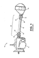
- a vehicle drive train system indicated generally at 10, that is conventional in the art.
- the illustrated drive train system 10 is intended merely to illustrate one environment in which this invention may be used.
- the scope of this invention is not intended to be limited for use with the specific structure for the vehicle drive train system 10 illustrated in Fig. 1 or with vehicle drive train systems in general.
- this invention may be used in any desired environment for the purposes described below.
- the illustrated vehicle drive train system 10 includes a transmission 12 that is connected to an axle assembly 14 through a driveshaft assembly 15.
- the driveshaft assembly 15 includes an elongated, cylindrically-shaped driveshaft tube 16.
- the output shaft (not shown) of the transmission 12 and the input shaft (not shown) of the axle assembly 14 are not co-axially aligned. Therefore, universal joints, indicated generally at 18, are provided at each end 20 of the driveshaft tube 16 to rotatably connect the driveshaft tube 16 at an angle relative to the output shaft of the transmission 12 and at an angle relative to the input shaft of the axle assembly 14.
- each end fitting 22 includes a tube seat (not shown) that is inserted into an open end 20 of the driveshaft tube 16.
- the end fittings 22 can be secured to the driveshaft tube 16 by welding, adhesives, or similar relatively permanent attachment methods. Accordingly, torque can be transmitted from the transmission 12 through the first end fitting 22, the driveshaft tube 16, and the second end fitting 22 to the axle assembly 14.
- Figs. 2 through 7 illustrate an improved method of manufacturing an axially collapsible driveshaft assembly that can be used, for example, in lieu of the conventional driveshaft tube 16 of the vehicular drive train system 10 illustrated in Fig. 1.
- a forming die indicated generally at 30, is provided.
- the forming die 30 includes a pair of opposed die sections 32 and 34 that are supported for relative movement between opened and closed positions.
- the die sections 32 and 34 have cooperating recesses 32a and 34a formed therein that together define an internal die cavity having a desired shape.
- the die sections 32 and 34 When moved to the opened position (not shown), the die sections 32 and 34 are spaced apart from one another to allow a workpiece to be inserted within or removed from the die cavity.
- the die sections 32 and 34 are disposed adjacent to one another so as to enclose the workpiece within the die cavity.
- the die cavity of the forming die 30 has a cross sectional shape that is generally circular, but having a circumference that is gently undulating or sinusoidal, as best shown in Fig. 4.
- the die cavity may be formed having any desired cross sectional shape (preferably non-circular, as will become apparent below).
- first and second hollow tubular members such as an inner tubular member 36 and an outer tubular member 40, are disposed in a concentric telescoping relationship, as shown in Fig. 2.
- the inner tubular member 36 and the outer tubular member 40 can be formed from any desired material or combination of materials. Typically, however, the inner tubular member 36 and the outer tubular member 40 are formed from steel or an aluminum alloy. Suitable methods for forming the inner tubular member 36 and the outer tubular member 40 are well known to persons skilled in the art. In the illustrated embodiment, the inner tubular member 36 and the outer tubular member 40 are both formed having a relatively constant outer diameter. However, if desired, either or both of the inner tubular member 36 and the outer tubular member 40 can be formed having a varying diameter or other cross sectional shape.
- the die sections 32 and 34 are initially moved to the opened position so that the axially overlapping inner and outer tubular members 36 and 40 can be inserted therebetween. Then, the die sections 32 and 34 of the forming die 30 are moved to the closed position about the concentric tubular members 36 and 40, as shown in Fig. 2. Next, as shown in Figs. 3 and 4, the inner tubular member 36 and the outer tubular member 40 are caused to be radially outwardly expanded. This expansion can be accomplished in any desired manner, such as by mechanical deformation, electromagnetic pulse forming, hydroforming, and the like.
- this central portion of the outer tubular member 40 is deformed outwardly into conformance with the shapes of the recesses 32a and 34a of the die sections 32 and 34, respectively.
- this central portion of the outer tubular member 40 is deformed to have a circumferentially undulating cross sectional shape, including a plurality of radially outwardly extending regions 44 and a plurality of radially inwardly extending regions 46, as best shown in Fig. 4.
- a portion of the inner tubular member 36 (i.e., the central portion of the inner tubular member 36 that is disposed within the outer tubular member 40 and within the die cavity) is deformed outwardly into conformance with the deformed inner surface (i.e., the plurality of radially outwardly extending regions 44 and the plurality of radially inwardly extending regions 46) of the outer tubular member 40.
- this portion of the inner tube 36 is also deformed to have a circumferentially undulating cross sectional shape, including a plurality of radially outwardly extending regions 48 and a plurality of radially inwardly extending regions 50.
- the plurality of radially outwardly extending regions 48 and the plurality of radially inwardly extending regions 50 of the inner tubular member 36 cooperate respectively with the plurality of radially outwardly extending regions 44 and the plurality of radially inwardly extending regions 46 of the outer tubular member 40 to function as a pair of splined members to provide a rotational driving connection between the inner tubular member 36 and the outer tubular member 40.
- the die cavity of the forming die 30 has a cross sectional shape that is generally circumferentially undulating. However, the die cavity of the forming die 30 may be formed having any desired (preferably non-circular) cross sectional shape. As further shown in Fig.
- the generally circumferentially undulating cross sectional shape of the forming die 30 provides for twelve outwardly extending regions and twelve inwardly extending regions.
- the die cavity may be formed to provide for any suitable number of outwardly extending regions and inwardly extending regions.
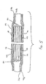
- the deformed inner and outer tubular members 36 and 40 are removed from the forming die 30, then divided into a first pair of tube sections including an first inner tube section 36a and a first outer tube section 40b and a second pair of tube sections including a second inner tube section 36b and a second outer tube section 40b.
- the inner and outer tubes 36 and 40 may be divided in this manner using any suitable method, such as by mechanical or laser cutting. However, a variety of other methods are well known to persons skilled in the art.
- the inner and outer tubular members 36 and 40 are cut at or near the center of the deformed portions thereof along a line that extends substantially perpendicular to the longitudinal axis thereof.
- Such a cut provides for two substantially identical pairs of tube sections 36a, 40a and 36b, 40b.
- Each of the inner tube sections 36a and 36b terminates in a deformed portion that includes the plurality of radially outwardly extending regions 48 and the plurality of radially inwardly extending regions 50 of the inner tubular member 36.
- each of the outer tube sections 40a and 40b terminates in a deformed portion that includes the plurality of radially outwardly extending regions 44 and the plurality of radially inwardly extending regions 46 of the outer tubular member 40.
- the outer tube sections 40a and 40b are then removed from the inner tube sections 36a and 36b, respectively, and re-oriented and aligned for assembly with one another as first and second driveshaft assemblies.
- the first inner tube section 36a is initially removed from the first outer tube section 40a.
- the first inner tube section 36a is re-oriented and aligned for assembly with the first outer tube section 40a, as shown in Fig. 6.
- the first inner tube section 36a is inserted telescopically within the first outer tube section 40a, as shown in Fig. 7, to form a first driveshaft assembly, indicated generally at 60 in Fig. 7.
- the plurality of radially outwardly extending regions 48 and the plurality of radially inwardly extending regions 50 of the first inner tube section 36a cooperate respectively with the plurality of radially outwardly extending regions 44 and the plurality of radially inwardly extending regions 46 of the first outer tube section 40a to function as a pair of splined members to provide a rotational driving connection between the first inner tube section 36a and the first outer tube section 40a.
- the first driveshaft assembly 60 has a co-axially overlapping splined region 61 that can accommodate relative axial movement between the first inner tube section 36 and the first outer tube section 40, as described above.
- the second inner tube section 36b and the second outer tube section 40b can be manipulated in a similar manner to form a second driveshaft assembly (not shown).
- the inner tubular member 36 and the outer tubular member 40 can be expanded at substantially the same time to achieve the desired shape within the forming die 30.
- expansion of the two members need not be simultaneous, but rather can be performed separately.
- the method of this invention can be performed by collapsing the inner tubular member 36 and the outer 40 radially inwardly about a mandrel (not shown) that is disposed within the inner tubular member 36 and includes an outer surface having a desired (generally circumferentially undulating, for example) cross sectional shape.
Landscapes
- Engineering & Computer Science (AREA)
- General Engineering & Computer Science (AREA)
- Mechanical Engineering (AREA)
- Ocean & Marine Engineering (AREA)
- Chemical & Material Sciences (AREA)
- Combustion & Propulsion (AREA)
- Transportation (AREA)
- Shafts, Cranks, Connecting Bars, And Related Bearings (AREA)
- Forging (AREA)
Abstract
Description
- This invention relates in general to drive train systems for transferring rotational power from a source of rotational power to a rotatably driven mechanism. In particular, this invention relates to an improved method of manufacturing an axially adjustable driveshaft assembly for use in such a drive train system.
- Torque transmitting shafts are widely used for transferring rotational power from a source of rotational power to a rotatably driven mechanism. For example, in most land vehicles in use today, a drive train system is provided for transmitting rotational power from an output shaft of an engine/transmission assembly to an input shaft of an axle assembly so as to rotatably drive the wheels of the vehicle. To accomplish this, a typical vehicular drive train system includes a hollow cylindrical driveshaft tube. A first universal joint is connected between the output shaft of the engine/transmission assembly and a first end of the driveshaft tube, while a second universal joint is connected between a second end of the driveshaft tube and the input shaft of the axle assembly. The universal joints provide a rotational driving connection from the output shaft of the engine/transmission assembly through the driveshaft tube to the input shaft of the axle assembly, while accommodating a limited amount of misalignment between the rotational axes of these three shafts.
- A recent trend in the development of passenger, sport utility, pickup truck, and other vehicles has been to design the various components of the vehicle in such a manner as to absorb energy during a collision, thereby providing additional safety to the occupants of the vehicle. As a part of this trend, it is known to design the drive train systems of vehicles so as to be axially collapsible so as to absorb energy during a collision. To accomplish this, the driveshaft tube may be formed as an assembly of first and second driveshaft sections that are connected together for concurrent rotational movement during normal operation, yet are capable of moving axially relative to one another when a relatively large axially compressive force is applied thereto, such as can occur during a collision. A variety of such axially collapsible driveshaft assemblies are known in the art. However, known methods of manufacturing such first and second driveshaft sections having been found to be relatively difficult, time consuming, expensive. Thus, it would be desirable to provide an improved method of manufacturing an axially collapsible driveshaft assembly for use in a drive train system that is relatively simple, quick, and inexpensive to perform.
- This invention relates to an improved method of manufacturing an axially collapsible driveshaft assembly, such as for use in a vehicular drive train system, that is relatively simple, quick, and inexpensive to perform. Initially, a first hollow tubular members is disposed in an axially overlapping relationship within a second hollow tubular member. The first and second tubular members are then disposed within a forming die having a die cavity that defines a non-circular cross-sectional shape. The central portions of the concentric tubular members are then expanded outwardly into conformance with the die cavity, such as by mechanical deformation, electromagnetic pulse forming, hydroforming, and the like. As a result of this expansion, the central portion of the outer second tubular member is deformed to have the same non-circular cross sectional shape as the die cavity, while the inner first tubular member is deformed to have the same non-circular cross sectional shape as the deformed outer first tubular member. The deformed first and second tubular members are then cut to provide two pairs of outer and inner tubular sections. Next, the outer tubular sections are removed from the associated inner tubular sections, and the inner tubular sections are oriented such that the deformed portions thereof are aligned with the deformed portions of the outer tubular sections. Lastly, the deformed portions of the inner tubular sections are inserted within the deformed portions of the outer tubular sections to form a pair of axially collapsible driveshaft assemblies.
- Various objects and advantages of this invention will become apparent to those skilled in the art from the following detailed description of the preferred embodiment, when read in light of the accompanying drawings.
-
- Fig. 1 is a side elevational view of a conventional vehicle drive train system including a driveshaft assembly that can be manufactured in accordance with the method of this invention.
- Fig. 2 is a sectional elevational view of a portion of a forming die having first and second hollow tubular members disposed therein, shown prior to deformation.
- Fig. 3 is a sectional elevational view similar to Fig. 2 showing the first and second hollow tubular members after deformation.
- Fig. 4 is a cross sectional view taken along line 4-4 of Fig. 3.
- Fig. 5 is a sectional elevational view of the deformed tubes illustrated in Figs. 3 and 4 showing the first and second hollow tubular members after being divided into first and second pairs of tube sections.
- Fig. 6 is a sectional elevational view showing the first pair of tube sections illustrated in Fig. 5 after the outer tubular section has been removed from the associated inner tubular section, and the inner tubular section has been re-oriented and aligned for assembly with the outer tubular section.
- Fig. 7 is a sectional elevational view similar to Fig. 6 showing the outer tubular section assembled with the inner tubular section to form an axially collapsible driveshaft assembly.
-
- Referring now to the drawings, there is illustrated in Fig. 1 a vehicle drive train system, indicated generally at 10, that is conventional in the art. The illustrated
drive train system 10 is intended merely to illustrate one environment in which this invention may be used. Thus, the scope of this invention is not intended to be limited for use with the specific structure for the vehicledrive train system 10 illustrated in Fig. 1 or with vehicle drive train systems in general. On the contrary, as will become apparent below, this invention may be used in any desired environment for the purposes described below. - The illustrated vehicle
drive train system 10 includes atransmission 12 that is connected to anaxle assembly 14 through adriveshaft assembly 15. Thedriveshaft assembly 15 includes an elongated, cylindrically-shaped driveshaft tube 16. As is typical in conventional vehicledrive train systems 10, the output shaft (not shown) of thetransmission 12 and the input shaft (not shown) of theaxle assembly 14 are not co-axially aligned. Therefore, universal joints, indicated generally at 18, are provided at eachend 20 of thedriveshaft tube 16 to rotatably connect thedriveshaft tube 16 at an angle relative to the output shaft of thetransmission 12 and at an angle relative to the input shaft of theaxle assembly 14. - The connections between the
ends 20 of thedriveshaft tube 16 and theuniversal joints 18 are usually accomplished by a pair ofend fittings 22, such as the illustrated tube yokes. Theends 20 of thedriveshaft tube 16 are open and are adapted to receive portions of theend fittings 22 therein. Typically, eachend fitting 22 includes a tube seat (not shown) that is inserted into anopen end 20 of thedriveshaft tube 16. Theend fittings 22 can be secured to thedriveshaft tube 16 by welding, adhesives, or similar relatively permanent attachment methods. Accordingly, torque can be transmitted from thetransmission 12 through the first end fitting 22, thedriveshaft tube 16, and the second end fitting 22 to theaxle assembly 14. - Figs. 2 through 7 illustrate an improved method of manufacturing an axially collapsible driveshaft assembly that can be used, for example, in lieu of the
conventional driveshaft tube 16 of the vehiculardrive train system 10 illustrated in Fig. 1. Initially, as shown in Fig. 2, a forming die, indicated generally at 30, is provided. The forming die 30 includes a pair of opposed diesections sections recesses 32a and 34a formed therein that together define an internal die cavity having a desired shape. When moved to the opened position (not shown), thedie sections die sections - To begin the manufacturing process, first and second hollow tubular members, such as an inner
tubular member 36 and an outertubular member 40, are disposed in a concentric telescoping relationship, as shown in Fig. 2. The innertubular member 36 and the outertubular member 40 can be formed from any desired material or combination of materials. Typically, however, the innertubular member 36 and the outertubular member 40 are formed from steel or an aluminum alloy. Suitable methods for forming the innertubular member 36 and the outertubular member 40 are well known to persons skilled in the art. In the illustrated embodiment, the innertubular member 36 and the outertubular member 40 are both formed having a relatively constant outer diameter. However, if desired, either or both of the innertubular member 36 and the outertubular member 40 can be formed having a varying diameter or other cross sectional shape. - The die
sections tubular members die sections tubular members tubular member 36 and the outertubular member 40 are caused to be radially outwardly expanded. This expansion can be accomplished in any desired manner, such as by mechanical deformation, electromagnetic pulse forming, hydroforming, and the like. As a result of this expansion, a portion of the outer tubular member 40 (i.e., the central portion of the outertubular member 40 that is disposed within the die cavity) is deformed outwardly into conformance with the shapes of therecesses 32a and 34a of thedie sections tubular member 40 is deformed to have a circumferentially undulating cross sectional shape, including a plurality of radially outwardly extendingregions 44 and a plurality of radially inwardly extendingregions 46, as best shown in Fig. 4. Similarly, a portion of the inner tubular member 36 (i.e., the central portion of theinner tubular member 36 that is disposed within the outertubular member 40 and within the die cavity) is deformed outwardly into conformance with the deformed inner surface (i.e., the plurality of radially outwardly extendingregions 44 and the plurality of radially inwardly extending regions 46) of the outertubular member 40. Thus, in the illustrated embodiment, this portion of theinner tube 36 is also deformed to have a circumferentially undulating cross sectional shape, including a plurality of radially outwardly extendingregions 48 and a plurality of radially inwardly extendingregions 50. - Accordingly, the plurality of radially outwardly extending
regions 48 and the plurality of radially inwardly extendingregions 50 of theinner tubular member 36 cooperate respectively with the plurality of radially outwardly extendingregions 44 and the plurality of radially inwardly extendingregions 46 of the outertubular member 40 to function as a pair of splined members to provide a rotational driving connection between theinner tubular member 36 and the outertubular member 40. As best shown in Fig. 4, the die cavity of the formingdie 30 has a cross sectional shape that is generally circumferentially undulating. However, the die cavity of the formingdie 30 may be formed having any desired (preferably non-circular) cross sectional shape. As further shown in Fig. 4, the generally circumferentially undulating cross sectional shape of the formingdie 30 provides for twelve outwardly extending regions and twelve inwardly extending regions. However, the die cavity may be formed to provide for any suitable number of outwardly extending regions and inwardly extending regions. - Next, as shown in Fig. 5, the deformed inner and outer
tubular members die 30, then divided into a first pair of tube sections including an firstinner tube section 36a and a first outer tube section 40b and a second pair of tube sections including a second inner tube section 36b and a second outer tube section 40b. The inner andouter tubes tubular members tube sections inner tube sections 36a and 36b terminates in a deformed portion that includes the plurality of radially outwardly extendingregions 48 and the plurality of radially inwardly extendingregions 50 of theinner tubular member 36. Similarly, each of theouter tube sections 40a and 40b terminates in a deformed portion that includes the plurality of radially outwardly extendingregions 44 and the plurality of radially inwardly extendingregions 46 of the outertubular member 40. - As shown in Fig. 6, the
outer tube sections 40a and 40b are then removed from theinner tube sections 36a and 36b, respectively, and re-oriented and aligned for assembly with one another as first and second driveshaft assemblies. To accomplish this, the firstinner tube section 36a is initially removed from the firstouter tube section 40a. Then, the firstinner tube section 36a is re-oriented and aligned for assembly with the firstouter tube section 40a, as shown in Fig. 6. Lastly, the firstinner tube section 36a is inserted telescopically within the firstouter tube section 40a, as shown in Fig. 7, to form a first driveshaft assembly, indicated generally at 60 in Fig. 7. When so inserted, the plurality of radially outwardly extendingregions 48 and the plurality of radially inwardly extendingregions 50 of the firstinner tube section 36a cooperate respectively with the plurality of radially outwardly extendingregions 44 and the plurality of radially inwardly extendingregions 46 of the firstouter tube section 40a to function as a pair of splined members to provide a rotational driving connection between the firstinner tube section 36a and the firstouter tube section 40a. Thus, thefirst driveshaft assembly 60 has a co-axially overlapping splinedregion 61 that can accommodate relative axial movement between the firstinner tube section 36 and the firstouter tube section 40, as described above. The second inner tube section 36b and the second outer tube section 40b can be manipulated in a similar manner to form a second driveshaft assembly (not shown). - As discussed above, the
inner tubular member 36 and the outertubular member 40 can be expanded at substantially the same time to achieve the desired shape within the formingdie 30. However, it will be appreciated that such expansion of the two members need not be simultaneous, but rather can be performed separately. Furthermore, it will be appreciated that the method of this invention can be performed by collapsing theinner tubular member 36 and the outer 40 radially inwardly about a mandrel (not shown) that is disposed within theinner tubular member 36 and includes an outer surface having a desired (generally circumferentially undulating, for example) cross sectional shape. - In accordance with the provisions of the patent statutes, the principle and mode of operation of this invention have been explained and illustrated in its preferred embodiment. However, it must be understood that this invention may be practiced otherwise than as specifically explained and illustrated without departing from its spirit or scope.
Claims (7)
- A method of manufacturing a pair of cooperating members comprising the steps of:(a) providing first and second members;(b) orienting portions of the first and second members in an axially overlapping relationship;(c) deforming regions of the axially overlapping portions of the first and second members;(d) removing the first and second members from the axially overlapping relationship; and(e) orienting the deformed regions of the first and second members in an axially overlapping relationship to provide a pair of cooperating members.
- The method defined in Claim 1 wherein said step (a) is performed by providing first and second tubular members.
- The method defined in Claim 1 wherein said step (c) is performed by one of mechanical deformation, electromagnetic pulse forming, and hydroforming.
- The method defined in Claim 1 wherein said (c) is performed by deforming regions of the axially overlapping portions of the first and second members to have a non-circular cross sectional shape.
- The method defined in Claim 1 wherein said step (c) is performed by deforming regions of the axially overlapping portions of the first and second members to have a circumferentially undulating cross sectional shape.
- The method defined in Claim 1 wherein said step (d) is performed by initially dividing the first and second members into a first pair of sections and a second pair of sections, then removing the first pair of sections from the axially overlapping relationship, and wherein said step (e) is performed by orienting the deformed regions of the first pair of sections in an axially overlapping relationship to provide a first pair of cooperating members.
- The method defined in Claim 6 wherein said step (d) is further performed by removing the second pair of sections from the axially overlapping relationship, and wherein said step (e) is performed by orienting the deformed regions of the second pair of sections in an axially overlapping relationship to provide a second pair of cooperating members.
Applications Claiming Priority (2)
| Application Number | Priority Date | Filing Date | Title |
|---|---|---|---|
| US37006602P | 2002-04-04 | 2002-04-04 | |
| US370066P | 2002-04-04 |
Publications (2)
| Publication Number | Publication Date |
|---|---|
| EP1350970A2 true EP1350970A2 (en) | 2003-10-08 |
| EP1350970A3 EP1350970A3 (en) | 2005-12-14 |
Family
ID=28042072
Family Applications (1)
| Application Number | Title | Priority Date | Filing Date |
|---|---|---|---|
| EP03252112A Withdrawn EP1350970A3 (en) | 2002-04-04 | 2003-04-03 | Method of manufacturing an axially collapsible driveshaft assembly |
Country Status (4)
| Country | Link |
|---|---|
| US (1) | US7080437B2 (en) |
| EP (1) | EP1350970A3 (en) |
| AU (1) | AU2003203496A1 (en) |
| BR (1) | BR0300861A (en) |
Cited By (3)
| Publication number | Priority date | Publication date | Assignee | Title |
|---|---|---|---|---|
| US7080437B2 (en) * | 2002-04-04 | 2006-07-25 | Torque-Traction Technologies Llc | Method of manufacturing an axially collapsible driveshaft assembly |
| DE102008015028A1 (en) * | 2008-03-19 | 2009-09-24 | Rauschnabel, Eberhard, Dr. | Massive hollow shafts e.g. drive shaft, connecting method, involves sliding connecting piece over profiled inner part, and completely or partially molding outer part in profile inner part by profiled tool or flexible reduction tool |
| EP2148101A1 (en) * | 2008-07-25 | 2010-01-27 | Bmw Ag | Shaft assembly with inner and outer shaft elements which can be moved into each other |
Families Citing this family (9)
| Publication number | Priority date | Publication date | Assignee | Title |
|---|---|---|---|---|
| US20050028341A1 (en) * | 2003-07-01 | 2005-02-10 | Durand Robert D. | Method of manufacturing a combined driveshaft tube and yoke assembly |
| WO2005053990A1 (en) * | 2003-12-03 | 2005-06-16 | Rotaform Gmbh | Tubular drive shaft, in particular a cardan shaft for a motor vehicle |
| US7181846B2 (en) * | 2004-07-08 | 2007-02-27 | Torque-Traction Technologies, Inc. | Method of manufacturing a combined driveshaft tube and yoke assembly |
| US8262491B2 (en) | 2008-07-25 | 2012-09-11 | GKN Driveline Newton, LLC | Driveshaft assembly and method for assembling driveshaft assembly |
| EP2686223B1 (en) * | 2011-03-17 | 2017-05-31 | Zephyros Inc. | Bonding assembly |
| US9028164B2 (en) | 2012-03-08 | 2015-05-12 | Dana Automotive Systems Group, Llc | Magnetic pulse formed vehicle driveshaft and method of making same |
| JP6137512B2 (en) | 2012-11-08 | 2017-05-31 | デーナ、オータモウティヴ、システィムズ、グループ、エルエルシー | Method for forming a drive shaft tube |
| US9890808B2 (en) | 2015-04-22 | 2018-02-13 | American Axle & Manufacturing, Inc. | Telescoping propshaft |
| US11493091B2 (en) | 2017-08-25 | 2022-11-08 | Dana Automotive Systems, Group, Llc | Propeller shaft crash collapse assembly |
Family Cites Families (24)
| Publication number | Priority date | Publication date | Assignee | Title |
|---|---|---|---|---|
| US1378442A (en) * | 1917-11-16 | 1921-05-17 | Lanston Monotype Machine Co | Process of corrugating cylindrical bodies |
| US3088761A (en) * | 1962-04-25 | 1963-05-07 | Aluminum Co Of America | Compressibly deformable connectors |
| US3685327A (en) * | 1969-11-12 | 1972-08-22 | Masanobu Nakamura | Bulging apparatus |
| DE2108913C3 (en) * | 1970-02-23 | 1975-05-28 | General Motors-Holden's Pty. Ltd., Port Melbourne, Victoria (Australien) | Rod or shaft, in particular steering shaft for motor vehicles, and method for their production |
| US4751835A (en) * | 1981-11-05 | 1988-06-21 | Ford Motor Company | Method of manufacturing variable diameter driveshaft |
| US5243874A (en) * | 1992-02-24 | 1993-09-14 | Pittsburgh Tubular Shafting, Inc. | Method and apparatus for telescopically assembling a pair of elongated members |
| US6015350A (en) * | 1997-12-03 | 2000-01-18 | Dana Corporation | Collapsible vehicle driveshaft |
| US5983497A (en) * | 1997-12-22 | 1999-11-16 | Dana Corporation | Method for forming a vehicle driveshaft tube |
| US6193612B1 (en) * | 1998-08-10 | 2001-02-27 | Ford Global Technologies, Inc. | Collapsible driveshaft |
| US6754943B1 (en) * | 1998-12-31 | 2004-06-29 | Torque-Traction Technologies, Inc. | Method of manufacturing an axially collapsible driveshaft assembly |
| US6484384B1 (en) * | 1998-12-31 | 2002-11-26 | Spicer Driveshaft, Inc. | Method of manufacturing an axially collapsible driveshaft assembly |
| US6138358A (en) * | 1999-02-18 | 2000-10-31 | Dana Corporation | Method of manufacturing a vehicle body and frame assembly |
| US6543266B1 (en) * | 1999-08-24 | 2003-04-08 | Magna International Inc. | Hydroformed collapsible driveshaft and steering shaft and methods of making the same |
| US6497030B1 (en) * | 1999-08-31 | 2002-12-24 | Dana Corporation | Method of manufacturing a lead screw and sleeve mechanism using a hydroforming process |
| US6519855B1 (en) * | 1999-08-31 | 2003-02-18 | Dana Corporation | Method of manufacturing a vehicle body and frame assembly |
| US6368225B1 (en) * | 1999-12-30 | 2002-04-09 | Spicer Driveshaft, Inc. | Axially collapsible driveshaft assembly and method of manufacturing same |
| US6666772B1 (en) * | 2000-01-31 | 2003-12-23 | Torque-Traction Technologies, Inc. | Axially collapsible driveshaft assembly |
| GB2371614B (en) * | 2001-01-26 | 2004-08-18 | Dana Corp | Method of manufacturing an axially collapsible driveshaft assembly |
| US6681488B2 (en) * | 2001-04-06 | 2004-01-27 | Dana Corporation | Method of manufacturing a vehicle body and frame assembly |
| US6912884B2 (en) * | 2001-06-25 | 2005-07-05 | Mohamed T. Gharib | Hydroforming process and apparatus for the same |
| US6698076B2 (en) * | 2002-01-07 | 2004-03-02 | Meritor Heavy Vehicle Systems, Llc | Drive shaft manufacturing process |
| BR0300861A (en) * | 2002-04-04 | 2005-03-01 | Dana Corp | Method of Fabricating a Pair of Cooperating Elements |
| US7007362B2 (en) * | 2003-04-29 | 2006-03-07 | Torque-Tractiontechnologies, Inc. | Method of forming a slip joint |
| US7181846B2 (en) * | 2004-07-08 | 2007-02-27 | Torque-Traction Technologies, Inc. | Method of manufacturing a combined driveshaft tube and yoke assembly |
-
2003
- 2003-04-03 BR BR0300861-4A patent/BR0300861A/en not_active IP Right Cessation
- 2003-04-03 EP EP03252112A patent/EP1350970A3/en not_active Withdrawn
- 2003-04-04 US US10/407,868 patent/US7080437B2/en not_active Expired - Fee Related
- 2003-04-04 AU AU2003203496A patent/AU2003203496A1/en not_active Abandoned
Non-Patent Citations (1)
| Title |
|---|
| None |
Cited By (3)
| Publication number | Priority date | Publication date | Assignee | Title |
|---|---|---|---|---|
| US7080437B2 (en) * | 2002-04-04 | 2006-07-25 | Torque-Traction Technologies Llc | Method of manufacturing an axially collapsible driveshaft assembly |
| DE102008015028A1 (en) * | 2008-03-19 | 2009-09-24 | Rauschnabel, Eberhard, Dr. | Massive hollow shafts e.g. drive shaft, connecting method, involves sliding connecting piece over profiled inner part, and completely or partially molding outer part in profile inner part by profiled tool or flexible reduction tool |
| EP2148101A1 (en) * | 2008-07-25 | 2010-01-27 | Bmw Ag | Shaft assembly with inner and outer shaft elements which can be moved into each other |
Also Published As
| Publication number | Publication date |
|---|---|
| US7080437B2 (en) | 2006-07-25 |
| BR0300861A (en) | 2005-03-01 |
| US20030213117A1 (en) | 2003-11-20 |
| AU2003203496A1 (en) | 2005-02-24 |
| EP1350970A3 (en) | 2005-12-14 |
Similar Documents
| Publication | Publication Date | Title |
|---|---|---|
| US6484384B1 (en) | Method of manufacturing an axially collapsible driveshaft assembly | |
| US6761503B2 (en) | Splined member for use in a slip joint and method of manufacturing the same | |
| US6371859B1 (en) | Axially collapsible driveshaft assembly | |
| US6193612B1 (en) | Collapsible driveshaft | |
| EP1375943B1 (en) | Rolling ball slip joint formed from two tubular members | |
| US6015350A (en) | Collapsible vehicle driveshaft | |
| US6368225B1 (en) | Axially collapsible driveshaft assembly and method of manufacturing same | |
| US7080437B2 (en) | Method of manufacturing an axially collapsible driveshaft assembly | |
| US6754943B1 (en) | Method of manufacturing an axially collapsible driveshaft assembly | |
| US7181846B2 (en) | Method of manufacturing a combined driveshaft tube and yoke assembly | |
| US6367680B1 (en) | Component for vehicular driveshaft assembly and method of manufacturing same | |
| US7080436B2 (en) | Method of manufacturing an axially collapsible driveshaft | |
| EP2272600A1 (en) | Method of manufacturing a splined member for use in a driveshaft assembly | |
| US20050028341A1 (en) | Method of manufacturing a combined driveshaft tube and yoke assembly | |
| EP1698787A2 (en) | Method of manufacturing an axially collapsible splined assembly | |
| WO2004071797A2 (en) | Improved propshaft having multiple crash features | |
| EP1674185A1 (en) | Method of manufacturing a splined member having a coating of a material applied thereto | |
| GB2371614A (en) | Method of manufacturing an axially collapsible driveshaft | |
| US20070129154A1 (en) | Propeller shaft assembly with integrated stub portion | |
| AU744548B1 (en) | Method of manufacturing an axially collapsible driveshaft assembly | |
| EP1724035B1 (en) | Method of manufacturing a driveshaft assembly | |
| US20060035714A1 (en) | Collapsible vehicle driveshaft | |
| MXPA00000376A (en) | Axially adjustable steering shaft assembly with ball spline |
Legal Events
| Date | Code | Title | Description |
|---|---|---|---|
| PUAI | Public reference made under article 153(3) epc to a published international application that has entered the european phase |
Free format text: ORIGINAL CODE: 0009012 |
|
| AK | Designated contracting states |
Kind code of ref document: A2 Designated state(s): AT BE BG CH CY CZ DE DK EE ES FI FR GB GR HU IE IT LI LU MC NL PT RO SE SI SK TR |
|
| AX | Request for extension of the european patent |
Extension state: AL LT LV MK |
|
| PUAL | Search report despatched |
Free format text: ORIGINAL CODE: 0009013 |
|
| AK | Designated contracting states |
Kind code of ref document: A3 Designated state(s): AT BE BG CH CY CZ DE DK EE ES FI FR GB GR HU IE IT LI LU MC NL PT RO SE SI SK TR |
|
| AX | Request for extension of the european patent |
Extension state: AL LT LV MK |
|
| AKX | Designation fees paid | ||
| REG | Reference to a national code |
Ref country code: DE Ref legal event code: 8566 |
|
| STAA | Information on the status of an ep patent application or granted ep patent |
Free format text: STATUS: THE APPLICATION IS DEEMED TO BE WITHDRAWN |
|
| 18D | Application deemed to be withdrawn |
Effective date: 20060616 |