EP1350965B1 - Spreizanker und Verfahren für seinen Einbau - Google Patents
Spreizanker und Verfahren für seinen Einbau Download PDFInfo
- Publication number
- EP1350965B1 EP1350965B1 EP03290849A EP03290849A EP1350965B1 EP 1350965 B1 EP1350965 B1 EP 1350965B1 EP 03290849 A EP03290849 A EP 03290849A EP 03290849 A EP03290849 A EP 03290849A EP 1350965 B1 EP1350965 B1 EP 1350965B1
- Authority
- EP
- European Patent Office
- Prior art keywords
- component
- mushrooming
- threaded
- expandable anchor
- hanger
- Prior art date
- Legal status (The legal status is an assumption and is not a legal conclusion. Google has not performed a legal analysis and makes no representation as to the accuracy of the status listed.)
- Expired - Fee Related
Links
- 238000000034 method Methods 0.000 title claims description 12
- 238000005553 drilling Methods 0.000 claims description 18
- 238000004873 anchoring Methods 0.000 claims description 8
- 230000000087 stabilizing effect Effects 0.000 claims 1
- 238000009434 installation Methods 0.000 description 9
- 239000000463 material Substances 0.000 description 8
- 235000001674 Agaricus brunnescens Nutrition 0.000 description 4
- 229910052751 metal Inorganic materials 0.000 description 3
- 239000002184 metal Substances 0.000 description 3
- 239000000047 product Substances 0.000 description 3
- 230000003213 activating effect Effects 0.000 description 1
- 239000004411 aluminium Substances 0.000 description 1
- 229910052782 aluminium Inorganic materials 0.000 description 1
- XAGFODPZIPBFFR-UHFFFAOYSA-N aluminium Chemical compound [Al] XAGFODPZIPBFFR-UHFFFAOYSA-N 0.000 description 1
- 239000004566 building material Substances 0.000 description 1
- 239000007795 chemical reaction product Substances 0.000 description 1
- 230000001010 compromised effect Effects 0.000 description 1
- 238000010276 construction Methods 0.000 description 1
- 238000000605 extraction Methods 0.000 description 1
- 238000007689 inspection Methods 0.000 description 1
- 238000012423 maintenance Methods 0.000 description 1
- 230000013011 mating Effects 0.000 description 1
- 150000002739 metals Chemical class 0.000 description 1
- 230000000149 penetrating effect Effects 0.000 description 1
- 238000009987 spinning Methods 0.000 description 1
Images

Classifications
-
- F—MECHANICAL ENGINEERING; LIGHTING; HEATING; WEAPONS; BLASTING
- F16—ENGINEERING ELEMENTS AND UNITS; GENERAL MEASURES FOR PRODUCING AND MAINTAINING EFFECTIVE FUNCTIONING OF MACHINES OR INSTALLATIONS; THERMAL INSULATION IN GENERAL
- F16B—DEVICES FOR FASTENING OR SECURING CONSTRUCTIONAL ELEMENTS OR MACHINE PARTS TOGETHER, e.g. NAILS, BOLTS, CIRCLIPS, CLAMPS, CLIPS OR WEDGES; JOINTS OR JOINTING
- F16B29/00—Screwed connection with deformation of nut or auxiliary member while fastening
-
- B—PERFORMING OPERATIONS; TRANSPORTING
- B25—HAND TOOLS; PORTABLE POWER-DRIVEN TOOLS; MANIPULATORS
- B25B—TOOLS OR BENCH DEVICES NOT OTHERWISE PROVIDED FOR, FOR FASTENING, CONNECTING, DISENGAGING OR HOLDING
- B25B27/00—Hand tools, specially adapted for fitting together or separating parts or objects whether or not involving some deformation, not otherwise provided for
- B25B27/0007—Tools for fixing internally screw-threaded tubular fasteners
-
- B—PERFORMING OPERATIONS; TRANSPORTING
- B25—HAND TOOLS; PORTABLE POWER-DRIVEN TOOLS; MANIPULATORS
- B25B—TOOLS OR BENCH DEVICES NOT OTHERWISE PROVIDED FOR, FOR FASTENING, CONNECTING, DISENGAGING OR HOLDING
- B25B31/00—Hand tools for applying fasteners
-
- F—MECHANICAL ENGINEERING; LIGHTING; HEATING; WEAPONS; BLASTING
- F16—ENGINEERING ELEMENTS AND UNITS; GENERAL MEASURES FOR PRODUCING AND MAINTAINING EFFECTIVE FUNCTIONING OF MACHINES OR INSTALLATIONS; THERMAL INSULATION IN GENERAL
- F16B—DEVICES FOR FASTENING OR SECURING CONSTRUCTIONAL ELEMENTS OR MACHINE PARTS TOGETHER, e.g. NAILS, BOLTS, CIRCLIPS, CLAMPS, CLIPS OR WEDGES; JOINTS OR JOINTING
- F16B13/00—Dowels or other devices fastened in walls or the like by inserting them in holes made therein for that purpose
- F16B13/002—Dowels or other devices fastened in walls or the like by inserting them in holes made therein for that purpose self-cutting
- F16B13/003—Dowels or other devices fastened in walls or the like by inserting them in holes made therein for that purpose self-cutting with a separate drilling bit attached to or surrounded by the dowel element
-
- F—MECHANICAL ENGINEERING; LIGHTING; HEATING; WEAPONS; BLASTING
- F16—ENGINEERING ELEMENTS AND UNITS; GENERAL MEASURES FOR PRODUCING AND MAINTAINING EFFECTIVE FUNCTIONING OF MACHINES OR INSTALLATIONS; THERMAL INSULATION IN GENERAL
- F16B—DEVICES FOR FASTENING OR SECURING CONSTRUCTIONAL ELEMENTS OR MACHINE PARTS TOGETHER, e.g. NAILS, BOLTS, CIRCLIPS, CLAMPS, CLIPS OR WEDGES; JOINTS OR JOINTING
- F16B13/00—Dowels or other devices fastened in walls or the like by inserting them in holes made therein for that purpose
- F16B13/04—Dowels or other devices fastened in walls or the like by inserting them in holes made therein for that purpose with parts gripping in the hole or behind the reverse side of the wall after inserting from the front
- F16B13/06—Dowels or other devices fastened in walls or the like by inserting them in holes made therein for that purpose with parts gripping in the hole or behind the reverse side of the wall after inserting from the front combined with expanding sleeve
- F16B13/061—Dowels or other devices fastened in walls or the like by inserting them in holes made therein for that purpose with parts gripping in the hole or behind the reverse side of the wall after inserting from the front combined with expanding sleeve of the buckling type
-
- F—MECHANICAL ENGINEERING; LIGHTING; HEATING; WEAPONS; BLASTING
- F16—ENGINEERING ELEMENTS AND UNITS; GENERAL MEASURES FOR PRODUCING AND MAINTAINING EFFECTIVE FUNCTIONING OF MACHINES OR INSTALLATIONS; THERMAL INSULATION IN GENERAL
- F16B—DEVICES FOR FASTENING OR SECURING CONSTRUCTIONAL ELEMENTS OR MACHINE PARTS TOGETHER, e.g. NAILS, BOLTS, CIRCLIPS, CLAMPS, CLIPS OR WEDGES; JOINTS OR JOINTING
- F16B35/00—Screw-bolts; Stay-bolts; Screw-threaded studs; Screws; Set screws
- F16B35/04—Screw-bolts; Stay-bolts; Screw-threaded studs; Screws; Set screws with specially-shaped head or shaft in order to fix the bolt on or in an object
- F16B35/06—Specially-shaped heads
Definitions
- This invention relates to self-expanding fasteners, which will not pull out of holes and more particularly for hanging pipe or other items inside buildings from overhead members.
- the mushrooming expandable anchor has two main components, the portion that collapses or mushrooms and a second threaded component that mechanically causes the collapse.
- the mushrooming component has a tubular body with a short section of internal threads on one end and a square flat washer on the opposite end.
- the tubular portion of the mushrooming component has slits in the sides, and the sides are slightly bowed out to promote symmetrical collapse.
- the tube is collapsed by a threaded screw rotated within the tubular body pulling the internally threaded section downwards towards the washer at the base.
- the mushrooming anchor when collapsed has radially extended anchoring strips preventing extraction of the fastener from a hole drilled in the support through which the fastener extends.
- the installer can first drill a hole through the support.
- the expandable anchor is then inserted into the hole and the internal threaded component is rotated collapsing the tubular body portion of the fastener.
- a drill point can be pressed into the tip of the expandable anchor for self-drilling through the support.
- the instant case relates to an anchor according to claim 1.
- US-A-3316796 teaches an anchor provided with penetrating prongs and its use is limited to walls into which the prongs can bear.
- the anchor is easy to use by simply placing the device in a socket attached to a drill and turning the socket.
- the drill point on the end of the expandable anchor drills a hole in the support it is to be held from.
- the anchor seats into the hole and an external socket end sleeve tool slides upward over the internal socket engaging the seated, unexpanded fastener.
- the exterior sleeve engages the square seated collar of the fastener preventing it from rotating.
- the interior socket is then rotated causing the expanding portion of the fasterner to collapse as the point of the internal threaded portion pushes the pressed in drill point from the anchor. This self-drilling option allows the installer to fasten and hang threaded rod from the floor.
- any given length of threaded rod can be installed into high ceilings with the limitations being (1) the length of the pole tool, which can be a telescoping tool comprised of aluminium tubes as are readily available in the market place and (2) the length of the threaded rod because the threaded rod must protrude from the lower end of the pole tool so it can be rotated within the pole tool independently.
- the fastener self drills and seats itself. Once seated, the extended pole tool (with the rod inside) is lifted and the notched exterior pole tool end engages the base of the expandable portion of the fastener prohibiting it from rotating.
- the next step is to turn the threaded rod causing the mushrooming portion of the fastener to collapse.
- the threaded rod remains installed in the fastener, allowing the worker to hang the intended load.
- the self-drilling expandable anchor can be constructed in a different manner.
- the collapsible mushrooming portion with a drill point can be placed in the inner socket and rotated by a drill to drill a hole in the support and seat the collapsible mushrooming portion that has a receiver head broached directly onto the opposite end of the drill point.
- a threaded component is incorporated within the assembly and collapses it by use of an internal screwdriver. The drill point is pushed from the top of the mushrooming portion by the advancing threaded component.
- a drill bit having a hex at it's base is placed in a drill to drill a hole in a support.
- a combination sleeve tool is placed over the drill bit and engages the hex at the drill bit base.
- the outer portion of the combination sleeve tool engages the collapsible mushrooming portion to keep it from turning and the threaded component of the expandable anchor is engaged by an internal drive/drive shaft.
- the expandable anchor is inserted into the drilled hole in the support and the internal threaded component is turned relative to the collapsible mushrooming portion to collapse it by operating the drill.
- an all thread rod may then be installed into the male receiver at the base of the threaded component.
- the hanger is now ready for its intended load.
- a cross drilled head in the base of the threaded component could hang wire or an adaptor bracket to allow the fastening of rods, bracing, bracketing or wire.
- the expandable anchor can have a fixed head or a swivel head.
- the expandable anchor provides a known pull out strength which is necessary for building safety while providing an easy to install method having a fool proof, no stripping, overturning or over torquing feature thus preventing breakage of the fastener which may cause failure and increase construction costs.
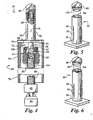
- Fig. 1 shows the self-drilling screw with expandable anchor 10 unassembled.
- the self-drilling screw having an expandable anchor 10 has three components parts.
- a hex head screw threaded component 20 similar to a SAMMY SUPER SCREW® sold by Speedy Products, Inc. owned by Illinois Tool Works, Inc. 3600 West Lake Avenue, Glenview, IL 60025-5811, a mushrooming component 30 similar to AVK Industrial Products A-R Series TM Threaded Insert, sold by AVK Industrial Products of Valencia, CA and a drill point 40.
- Fig. 1 also shows tools used to install the mushrooming expandable anchor 10.
- the tools include a socket 50 for turning the hex head screw 20, a sleeve tool 70 for engaging the expandable anchor 30, an internally broached drive shaft 80 for engaging the socket 50, a drive tool/adaptor 83 having a hex adaptor portion 82 to turn the above described assembly and adapt to drill bit 81, if a drill point 40 is not included in the assembly, and finally drill 84.
- the drill point 40 has a slightly larger diameter than the mushrooming component 30 such that it can cut a hole in a support 60 and allow the mushrooming portion 35 of the expandable anchor body 30 to fit through the drilled hole.
- the mushrooming component 30 is basically a cylinder having an internal threaded portion 34 near the top and a base 38 at the bottom. Slots 36 are cut through the cylinder walls in several locations around the mushrooming component 30 so that it can be compressed and split apart along the slits to form anchoring strips 37 when the mushrooming component 30 is collapsed as shown in Figs. 3 and 7 .
- the mushrooming component 30 is formed with a bulge 35 in the walls to facilitate the collapse of anchoring strips 37.
- mushrooming component 30 is shown as a cylindrical body 35 with a circular cross section in the figures it can be any shape with any cross section such as an octagon, hexagon, square, or oval etc. as long as it will fit through the hole drilled in the support and collapse as shown herein.
- the hex head component 20 has a hex head portion 22, a base portion 24 and a screw shaft 26 having a diameter just smaller than the inside threaded diameter 34 of the mushrooming component 30.
- the shaft 26 has a threaded section 28 on the top portion for engaging the threads 34 in the mushrooming component 30.
- the inside threads 34 in mushrooming component 30 are threaded onto the threads 28 on the screw shaft 26 of hex head screw 20 by a few turns.
- the hex head screw 20 is placed in a socket 50 having a hexagon wall 58 on a portion of the inside surface for mating with the hex head portion 22 of hex head screw 20.
- the hex head screw 20 can then be turned by the socket 50.
- a sleeve tool 70 has an inside diameter which fits over the outside diameter of the socket 50 such that the socket 50 can rotate inside the sleeve tool 70 when desired.
- the sleeve tool 70 has notches 72 for engaging the corners 74 of the base 38 of the mushrooming component 30.
- Sleeve tool 70 can either be a hand held tool on the order of 30 to 40 cm long or an expandable pole tool that can be extended to any length.
- the sleeve tool 70 may have a hand gripping means to hold it in place while the socket 50 is being turned therein.
- the socket 50 has a hex shaft 52 for connection to internally broached drive shaft 80 which allows connection to machined part 83 having a hex adapter portion 82, as seen in Fig. 1 .
- a driving means 84 such as an electric or battery operated drill, air powered drill or the like can rotate the assembly.
- the driving means 84 is connected to the drive shaft 80 to drive socket 50 by part 83, which optionally holds disposable drill bit 81.
- the driving means 84 will turn drill point 40 on the top of mushrooming component 30 to cut through a support 60, which may be a thin metal decking, beams, supports, Z purlin, bar joist, roof decking, or other truss materials. After the drill point 40 has cut through the support 60 the drill point 40 is no longer needed.
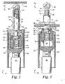
- the next step in the process is to collapse or mushroom the mushrooming component 30, as seen in Fig. 3 to secure it from being pulled out of the support 60.
- the driving means 84 will now rotate the combination of socket 50 and drive shaft 80 while the installer is holding the sleeve tool 70 in a fixed position such that the hex head screw 20 can rotate relative to the mushrooming component 30 thus rotating the threads 28 of the screw.
- the threads 28 are only on a portion of the top of the screw shaft 26.
- the internal threaded portion 34 of the mushrooming component 30 is also only on a top portion of the mushrooming component 30.
- the relative length of the threaded portions 28 and 34 on the screw shaft 26 and the mushrooming component 30 respectively are such that as the hex head screw 20 is turned relative to the mushrooming component 30 the top of the mushrooming component 30 will be pulled downward allowing the bowed portion 35 having the slots 36 to collapse, forming anchoring strips 37 as seen in Figs. 3 and 7 .
- Base 38 will be pulled up against the bottom of support 60 and will not fit through the drilled hole therein. As the hex head screw 20 is turned relative to the mushrooming component 30 the anchoring strips 37 will be flattened out.
- the anchoring strips 37 will not fit through the hole self-drilled by drill point 40 offering a pull out strength strong enough to support whatever the hanger is to be attached to. As shown in Fig. 2, 3 , 4 , 7 the internal hanger threads 25 in the bottom portion of the hex head screw 20 are available to hold whatever is screwed into the hanger threads 25 or alternatively a cross drilled hole 46 may be incorporated to allow attachment of a great variety of adaptors.
- the pull out strength can vary depending on the support material 60.
- the drill point 40 is expelled from the top of the mushrooming component 30 by the top of the screw shaft 26 as it pushes through the top of the expandable anchor 30. The drill point 40 will then fall out and may land on the support 60.
- the lengths of the threaded portions 28 and 34 on the screw shaft 26 and the mushrooming component 30 respectively are such that the threads 28 on the screw shaft 26 will exit the top threads 34 on the mushrooming component 30 allowing the hex head screw 20 to spin freely thereafter when the expandable anchor 10 is compressed to the desired amount.
- This spin free feature eliminates possible over torque or fracture of components incorporated in fastener 10.
- the drill point 40 can be connected to the mushrooming component 30 in many different ways.
- the drill point 40 is swaged into the mushrooming component 30.
- the drill point 40 has teeth 130 for engaging the mushrooming component 30.
- the drill point 40 has teeth notches 44 for engaging posts 45 of the mushrooming component 30.
- the socket 50 When self-drilling a hole in the support 60 the socket 50 turns the hex head screw 20 while notches 72 in sleeve 70 engage the comers 74 of the base 38 on the mushrooming component 30.
- the socket 50 turns the screw 20 the mushrooming component 30 and sleeve 70 will spin with the screw 20 since it takes a great deal of force to turn the threads 28 on screw 20 into the threads 34 of mushrooming component 30. Therefore the drilling can be accomplished without collapsing the mushrooming component 30.
- the sleeve 70 is held to keep it from rotating then the mushrooming component 30 will collapse. Alternatively the sleeve 70 will not be placed into engagement with the mushrooming component 30 and held from spinning until it is desired to collapse the mushrooming component 30.
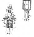
- hex head screw 20 There can be many different varieties of hex head screw 20. As shown in Fig. 1 the screw shaft 26 is integral with or fixed in the base 24. Alternatively as shown in Figs. 2, 3 , 4 , and 7 the hex head screw 20 is an assembly of two parts, the base portion 124 with a hex head base 22 and a screw 126 having screw shaft 26 with threads 28, a screw hex head 29 having a rim 23. The hex head 29 on screw 126 mates with a hex head receiving portion 31 in the base portion 124 of hex head screw 20.
- the screw 126 with a hex head 29 can be a standard screw, which can be purchased in bulk at low prices from any number of suppliers.
- the base portion 124 can have the hex head receiving portion 31 for receiving the hex head 29 of screw 126 and then folding a flange 27 over the rim 23 to keep the screw 126 in place relative to the base portion 124.
- the flange 27 can be some distance from the hex head receiving portion 31 providing space 33 for a dome portion within the base portion 124, as shown in Fig. 7 .
- the dome portion 33 allows the screw hex head 29 to broach into the hex head receiving portion 31 when it is desired to fix the screw in position while in use for compressing the expandable anchor 30 and thereafter to release the screw hex head 29 from the hex head receiving portion 31 so that it can swivel freely in the domed portion 33.
- a disposable drill bit 81 fits into machine part 83 that has a hex adaptor portion 82 having a set screw 87. This fits into a drill chuck 84 to drill a hole in a support 60.
- the drill bit 40 is not used.
- a drive shaft 80 having interior hex portions 53 on both ends attaches to the hex portion 82 of the bit adaptor and hex portion 52 of a socket 50 allowing the rotation of part 20 while sleeve 70 prevents rotation of mushrooming component 30. In this manner an installer can use the assembly repeatedly without rechecking his drill.
- the screw with expandable anchor 10 with a drill point 40 thereon can be used with a pole installation method such that the installer need not be on a ladder adjacent the support 60 to drill a hole therein. He can stand on the floor and move about freely without having to reposition a ladder for each installation operation. With this method the installer can also access the support 60 through narrow gaps between pipes, vents or other equipment. The pole and equipment attached thereto can be held at a position considerably below the support 60 for self-drilling a hole therein and collapsing the collapsible anchor 10. To use this method a threaded rod 90 as seen in Fig.
- a long or an extendable pole tool 70 can be used with the threaded rod to match the length of the threaded rod.
- drill chuck 84 receives internally threaded driver 85, which accepts a length of threaded rod 90. Threaded rod 90 must protrude from the lower end of pole tool 70. By rotating the assembly comprising the drill chuck 84, the driver 85, the threaded rod 90, part 10 and the drill point 40 will self drill through material 60. Once drilling is complete, pole tool 70 is raised to engage collar 74 of seated collapsible anchor portion 30.
- pole tool 70 grasps pole tool 70 preventing it from rotating while activating drill 84 thus turning threaded rod 90 and internal screw 20 causing collapse of mushrooming component 30. Then pole tool 70 is slid down leaving the complete fastener assembly 10 with threaded rod 90 ready for the intended load to be attached.
- the pole tool 70 can be extendable to be used with different lengths of rods 90.
- the installer would prefer to use an embodiment with no drill tip 40 on the mushrooming component 30 he would have to first drill a hole in the support 60 with a drill 84 and the assembly comprising disposable drill bit 81, and adaptor 83, and then install the collapsible anchor 10 as described above.
- the base of the screw 20 has internal threads 25 providing a connection to the object to be hung therefrom, however the base of screw 20 may use any means of attaching an object thereto.
- a hole 46 cross drilled through the hex head portion 22 can be used to insert a rod or bolt (not shown) for hanging an object or bracket by use of the hole 46.
Claims (16)
- Spreizanker (10), der Folgendes umfasst:eine Gewindekomponente (20) mit einem Schaft (26), der ein Gewinde (28) aufweist, einen Aufhängerteil zur Befestigung von daran aufgehängten Objekten und einen Werkzeugeingriffsteil (22) zum Eingriff mit einem Drehwerkzeug (50),eine zusammenlegbare Komponente (30) mit einem länglichen Körper (35), der einen ein Innengewinde aufweisenden Teil (34) aufweist, wobei der längliche Körper Schlitze (36) zum Bilden von radialen Verankerungsstreifen (37), wenn der Körper in Längsrichtung komprimiert wird, aufweist, dadurch gekennzeichnet, dass die zusammenlegbare Komponente (30) eine Basis (38) zum Eingriff mit einem Stabilisierungswerkzeug (70) aufweist, um die Basis am Drehen zu hindern, wenn die Gewindekomponente (20) bezüglich der zusammenlegbaren Komponente (30) gedreht wird, während ihre jeweiligen Gewinde zur Längskomprimierung des geschlitzten länglichen Körpers (35) der zusammenlegbaren Komponente (30) in Eingriff gelangen.
- Spreizanker nach Anspruch 1, der weiterhin Folgendes umfasst:eine Bohrspitze (40), die an der zusammenlegbaren Komponente (30) so befestigt ist, dass die Bohrspitze (40) ein Loch in einen Träger (60) bohren kann, wenn sich die zusammenlegbare Komponente dreht.
- Spreizanker nach einem der Ansprüche 1 und 2,
wobei
der Werkzeugeingriffsteil (22) der Gewindekomponente (20) einen geformten Außenumfang am Aufhängerteil zum Eingriff mit einem Drehwerkzeug umfasst. - Spreizanker nach einem der Ansprüche 1 bis 3,
wobei
der Werkzeugeingriffsteil der Gewindekomponente einen Schraubkopf (22) auf dem Schaft (26) umfasst. - Spreizanker nach einem der Ansprüche 1 bis 4,
wobei
der Schaft (26) der Gewindekomponente einen Sechskantkopf (29) aufweist, der sich in einen Sechskantkopfaufnahmeteil (31) des Aufhängerteils hineindrückt, um den Gewindeschaft gegen Drehung bezüglich des Aufhängerteils festzulegen. - Spreizanker nach Anspruch 5, wobei
eine Gewindekomponente (20) einen Rand (23) neben dem Sechskantkopf (29) aufweist und der Aufhängerteil einen Flansch (27) zum Verhindern, dass sich der Rand am Sechskantkopf auf dem Schaft aus dem Sechskantkopfaufnahmeteil des Aufhängerteils hinaus bewegt, aufweist. - Spreizanker nach Anspruch 6, wobei
ein kuppelförmiger Teil (33) des Aufhängerteils (124) einen Raum zwischen dem Rand (23) und dem Sechskantkopfaufnahmeteil (31) bereitstellt, so dass der Sechskantkopf der Gewindekomponente (29) frei hängen kann und außer Eingriff von dem Sechskantkopfaufnahmeteil (31) ist, so dass der Aufhängerteil bezüglich des Schafts schwenken kann. - Spreizanker nach einem der Ansprüche 2 bis 7,
wobei
der Werkzeugeingriffsteil (22) der Gewindekomponente einen geformten Außenumfang am Aufhängerteil umfasst. - Spreizanker nach einem der Ansprüche 2 bis 8,
wobei
der Werkzeugeingriffsteil (22) der Gewindekomponente einen Schraubkopf auf dem Schaft aufweist. - Spreizanker nach einem der Ansprüche 1 bis 9,
wobei
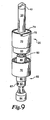
die zusammenlegbare Komponente (230) an einem Ende einen Flansch aufweist und
die Gewindekomponente (20) einen länglichen Körper mit einem Außengewinde (228) zum Eingriff mit dem Innengewinde (234) der zusammenlegbaren Komponente (230) und einen Kopf (125) mit einem Schlitz (129) darin zum Drehen der Gewindekomponente bezüglich der zusammenlegbaren Komponente aufweist,
eine Aufhängerkomponente (22) an der zusammenlegbaren Komponente (230) zur Befestigung von daran aufgehängten Objekten aufweist, wobei die Aufhängerkomponente eine mittlere Öffnung zur Bereitstellung von Zugang zu dem Kopf (125) der Gewindekomponente aufweist. - Spreizanker nach einem der Ansprüche 1 bis 10,
wobei
sich das Gewinde (28) der Gewindekomponente und das Gewinde (34) der zusammenlegbaren Komponente in einer gewünschten Länge erstrecken, um sich gegenseitig in Eingriff zu nehmen, so dass der zusammenlegbare Teil um eine bekannte Länge zusammenfällt und sie sich dann bezüglich einander frei drehen. - Spreizanker nach einem der Ansprüche 2 bis 11,
wobei
die Bohrspitze (40) von dem Schaft der Gewindekomponente (20) in Eingriff genommen wird und von der zusammenlegbaren Komponente (30) heruntergedrückt wird, während der zusammenlegbare Teil zusammenfällt. - Spreizanker nach einem der Ansprüche 1 bis 12,
wobei
der mit einem Gewinde versehene Hängerteil ein Innengewinde (25) aufweist,
eine Gewindestange zum Ineingriffnehmen des Gewindes an dem mit einem Gewinde versehenen Aufhängerteil vorgesehen ist, so dass sich die Gewindestange bei ihrer Drehung selbst in die Gewindekomponente schraubt und sie dann dreht,
wobei letztere wiederum die selbstbohrende zusammenlegbare Komponente (30) dreht, mit der sie verschraubt ist. - Verfahren zum Einbau eines Spreizankers mit den folgenden Schritten:Bohren eines Lochs in einen Träger (60),Einführen eines vormontierten Spreizankers nach Anspruch 7, der eine Gewindekomponente (20) und eine zusammenlegbare Komponente (30) aufweist, in das Loch,wobei die Gewindekomponente (20) einen Sechskantschraubkopf (29) aufweist,
Drehen der Gewindekomponente bezüglich der zusammenlegbaren Komponente, damit die zusammenlegbare Komponente zusammenfällt, um die Verankerungsstreifen (37) über das Loch in dem Träger radial auszustrecken, und
Herausziehen des Sechskantschraubkopfs (29) aus einem aufgeriebenen Adapterkopfteil (22), so dass der Sechskantschraubkopf (29) bezüglich des Aufhängerteils (124) frei schwenkt. - Verfahren zum Einbau eines Spreizankers nach Anspruch 14, weiterhin mit dem Schritt des
Drehens der Gewindekomponente (20) bezüglich der zusammenlegbaren Komponente (30), bis die Gewindeteile einander passieren und die Gewindekomponente bezüglich der zusammenlegbaren Komponente (30) ausrückt und sich frei dreht, wodurch das Ausmaß des Zusammenfallens der zusammenlegbaren Komponente gesteuert wird, um die Herausziehstärke zu erzeugen. - Verfahren zum Einbau eines Spreizankers nach Anspruch 14, weiterhin mit dem Schritt des
Herausschiebens der Bohrspitze (40) aus dem oberen Ende der zusammenlegbaren Komponente (30) durch Drehen der Gewindekomponente (20) bezüglich der zusammenlegbaren Komponente (30).
Applications Claiming Priority (4)
| Application Number | Priority Date | Filing Date | Title |
|---|---|---|---|
| US37048702P | 2002-04-05 | 2002-04-05 | |
| US370487P | 2002-04-05 | ||
| US10/213,795 US6935821B2 (en) | 2002-04-05 | 2002-08-07 | Mushrooming expandable anchor |
| US213795 | 2002-08-07 |
Publications (3)
| Publication Number | Publication Date |
|---|---|
| EP1350965A2 EP1350965A2 (de) | 2003-10-08 |
| EP1350965A3 EP1350965A3 (de) | 2003-12-17 |
| EP1350965B1 true EP1350965B1 (de) | 2009-08-26 |
Family
ID=28044509
Family Applications (1)
| Application Number | Title | Priority Date | Filing Date |
|---|---|---|---|
| EP03290849A Expired - Fee Related EP1350965B1 (de) | 2002-04-05 | 2003-04-04 | Spreizanker und Verfahren für seinen Einbau |
Country Status (6)
| Country | Link |
|---|---|
| US (3) | US6935821B2 (de) |
| EP (1) | EP1350965B1 (de) |
| JP (1) | JP4387683B2 (de) |
| CA (1) | CA2424411C (de) |
| DE (1) | DE60328936D1 (de) |
| MX (1) | MXPA03002708A (de) |
Families Citing this family (65)
| Publication number | Priority date | Publication date | Assignee | Title |
|---|---|---|---|---|
| US6935821B2 (en) * | 2002-04-05 | 2005-08-30 | Illinois Tool Works, Inc. | Mushrooming expandable anchor |
| US7120979B1 (en) * | 2003-04-21 | 2006-10-17 | Glover William T | Light bulb socket burnishing tool |
| US8057144B2 (en) * | 2004-08-27 | 2011-11-15 | Fatigue Technology, Inc. | Sealed, blind fastener assembly |
| US20060048611A1 (en) * | 2004-09-07 | 2006-03-09 | Illinois Tool Works | Panel fastening and waterproofing anchor |
| US20060067803A1 (en) * | 2004-09-27 | 2006-03-30 | Hsu Chin J | Self-drilling wall anchor device |
| US20060078399A1 (en) * | 2004-10-13 | 2006-04-13 | Fatigue Technology, Inc. | Blindly installed, reinforceable nuts for joining structural members |
| AU2007220986A1 (en) * | 2006-02-28 | 2007-09-07 | Monogram Aerospace Fasteners, Inc. | Mechanically locked blind bolt fastener |
| AU2007225008B2 (en) * | 2006-03-13 | 2013-09-05 | Domenico Nardi | A self-drilling masonry bolt |
| US20070258786A1 (en) * | 2006-05-03 | 2007-11-08 | Sherex Fastening Solutions, Llc | Rivet-like fastener with floating nut |
| US7802948B1 (en) * | 2006-06-07 | 2010-09-28 | Matthew R Bastiaans | Drill extender |
| US7780134B2 (en) * | 2006-06-14 | 2010-08-24 | Illinois Tool Works Inc. | Anchor assembly with large range of motion suspension members, and restraint systems for suspended components |
| US20080008553A1 (en) * | 2006-07-10 | 2008-01-10 | Robert Andrew Gillis | Self-drilling anchor screw and method of using the same |
| US20080016667A1 (en) * | 2006-07-21 | 2008-01-24 | Acument Intellectual Properties, Llc | Self-piercing blind nut insert |
| DE202006013142U1 (de) | 2006-08-26 | 2006-11-16 | Textron Verbindungstechnik Gmbh & Co. Ohg | Selbstbohrendes Blindniet |
| US8398345B2 (en) * | 2006-10-05 | 2013-03-19 | Monogram Aerospace Fasteners, Inc. | Low profile dual-action disposable clamp |
| US8517649B2 (en) * | 2006-10-05 | 2013-08-27 | Monogram Aerospace Fasteners, Inc. | Dual-action disposable clamp |
| US8511952B2 (en) | 2006-10-05 | 2013-08-20 | Monogram Aerospace Fasteners, Inc. | Dual-action disposable clamp |
| MY147466A (en) * | 2006-10-06 | 2012-12-14 | Liow Kok Hua | An improved sleeve anchor |
| DE102007009618B4 (de) * | 2007-02-26 | 2010-03-18 | Gesipa Blindniettechnik Gmbh | Setzvorrichtung für eine Befestigungseinheit |
| US20090158567A1 (en) * | 2007-12-21 | 2009-06-25 | Geoffrey Scott Fulton | Apparatus, system, and method for fastening screw and sheath anchors |
| US8061000B2 (en) * | 2008-06-06 | 2011-11-22 | Black & Decker Inc. | Anchor installation tool |
| US8602285B2 (en) * | 2008-06-06 | 2013-12-10 | Black & Decker | Anchor installation tool |
| US20100064522A1 (en) * | 2008-09-15 | 2010-03-18 | Commscope, Inc. Of North Carolina | Coaxial cable end preparation tool with drive shaft and related methods |
| US20100122926A1 (en) * | 2008-11-17 | 2010-05-20 | Tocco Anthony T | Tool bit exchange system and method |
| US8132373B2 (en) * | 2008-12-27 | 2012-03-13 | Radzat Gary F | Modular building panel hanging system |
| US20100228301A1 (en) * | 2009-03-09 | 2010-09-09 | Greenhalgh E Skott | Attachment device and methods of use |
| IL197620A (en) * | 2009-03-16 | 2010-12-30 | Aharon Ravitz | Method of reinforcing a waffle-structure ceiling and ceiling reinforced thereby |
| US8302708B1 (en) * | 2009-05-12 | 2012-11-06 | Dover Bmcs Acquisition Corporation | Rotational drill wrenches and drilling apparatuses including the same |
| US8854829B1 (en) * | 2009-09-01 | 2014-10-07 | Raytheon Company | Standoff mounting system |
| CN102159351B (zh) * | 2009-12-08 | 2014-12-17 | Osg株式会社 | 不重磨式旋转工具 |
| US9931721B2 (en) * | 2009-12-18 | 2018-04-03 | Accelerated Fastening, LLC | Installation system for ceiling mounted items |
| US8479617B2 (en) | 2010-03-22 | 2013-07-09 | American Airlines, Inc. | Portable cylinder assembly torque tool |
| CN102837285A (zh) * | 2011-06-24 | 2012-12-26 | 周水生 | 水管断头启拔器 |
| US8979459B2 (en) | 2012-11-19 | 2015-03-17 | Infastech Intellectual Properties Pte. Ltd. | Combination hanger fastener |
| DE102013002734B4 (de) * | 2013-02-19 | 2015-03-05 | Firep Rebar Technology Gmbh | Ankerkopf für einen Zuganker und Ankermutter für einen Ankerkopf eines Zugankers |
| CN103196601B (zh) * | 2013-03-07 | 2014-11-19 | 航天精工股份有限公司 | 一种利用检测装置测定法兰面螺栓安装力矩的方法 |
| WO2014178036A1 (en) | 2013-05-02 | 2014-11-06 | Ornit Agriculture Industry Business And Management Agricultural Cooperative Association Ltd. | Blind rivet |
| KR101532246B1 (ko) * | 2013-08-09 | 2015-06-29 | 주식회사 성우하이텍 | 리벳 너트 유닛 |
| US20150352705A1 (en) * | 2014-06-06 | 2015-12-10 | KV Innovations, LLC | System and Method for Installing Fixtures in Tight Spaces |
| US20160160906A1 (en) * | 2014-12-05 | 2016-06-09 | Black & Decker Inc. | Swivel hanger |
| US10132347B2 (en) * | 2014-12-05 | 2018-11-20 | Black & Decker Inc. | Swivel hanger system |
| WO2016196880A1 (en) | 2015-06-05 | 2016-12-08 | Todd Johnson | Valve stem assemblies |
| JP6703221B2 (ja) * | 2016-06-30 | 2020-06-03 | 若井ホールディングス株式会社 | ボードアンカーの施工用工具 |
| DE102016113897B4 (de) * | 2016-07-27 | 2019-05-09 | Schmiedestück-Vertrieb Feuerstein Gmbh | Schwerlastschäkel |
| US10323426B1 (en) | 2017-04-06 | 2019-06-18 | Kent Sandvig | Wall repair plug system |
| EP3418589A1 (de) * | 2017-06-22 | 2018-12-26 | Metso Sweden Ab | Verfahren und befestigungsvorrichtung zur befestigung eines verkleidungselementes |
| US10794415B2 (en) * | 2017-06-30 | 2020-10-06 | Bollhoff Inc. | Threaded blind fastener and spacer assembly and methods for the assembly and use thereof |
| US11137008B2 (en) | 2018-01-12 | 2021-10-05 | Illinois Tool Works Inc. | Self-drilling anchor assembly |
| AU2019307708A1 (en) * | 2018-07-17 | 2020-12-10 | Hilti Aktiengesellschaft | Systems and methods for a combination tool utilized with an anchoring system |
| US11692578B2 (en) | 2018-09-26 | 2023-07-04 | Illinois Tool Works Inc. | Post-to-beam fastener |
| USD886172S1 (en) | 2019-01-09 | 2020-06-02 | Illinois Tool Works Inc. | Anchor assembly drill bit |
| USD886171S1 (en) | 2019-01-09 | 2020-06-02 | Illinois Tool Works Inc. | Anchor assembly drill bit |
| USD886169S1 (en) | 2019-01-09 | 2020-06-02 | Illinois Tool Works Inc. | Anchor assembly drill bit |
| USD886170S1 (en) | 2019-01-09 | 2020-06-02 | Illinois Tool Works Inc. | Anchor assembly drill bit |
| USD889948S1 (en) | 2019-01-09 | 2020-07-14 | Illinois Tool Works Inc. | Anchor assembly sleeve |
| USD889950S1 (en) | 2019-01-09 | 2020-07-14 | Illinois Tool Works Inc. | Anchor assembly sleeve |
| USD889949S1 (en) | 2019-01-09 | 2020-07-14 | Illinois Tool Works Inc. | Anchor assembly sleeve |
| USD886168S1 (en) | 2019-01-09 | 2020-06-02 | Illinois Tool Works Inc. | Anchor assembly drill bit |
| US10933477B1 (en) * | 2020-02-12 | 2021-03-02 | Varun Jay Patel | Wall magnet anchor system |
| US20210372449A1 (en) * | 2020-05-28 | 2021-12-02 | Illinois Tool Works Inc. | Self-drilling expandable anchor and methods of use and installation thereof |
| US11759921B2 (en) * | 2020-05-28 | 2023-09-19 | Illinois Tool Works Inc. | Self-drilling expandable anchor installation tool and methods of use thereof |
| CN113864304B (zh) * | 2020-06-30 | 2023-06-13 | 喜利得股份公司 | 用于自钻孔锚栓的安装设备及安装方法 |
| US11833577B2 (en) | 2021-02-16 | 2023-12-05 | Scott Horton | Mushrooming expandable fastener installation tool and methods |
| EP4292766A1 (de) | 2022-04-05 | 2023-12-20 | Illinois Tool Works Inc. | Werkzeug zur installation eines expandierbaren ankers und verfahren zur verwendung davon |
| US20230332635A1 (en) * | 2022-04-18 | 2023-10-19 | Robert Tzorany | Drywall Sleeve Anchor |
Citations (1)
| Publication number | Priority date | Publication date | Assignee | Title |
|---|---|---|---|---|
| US5518351A (en) * | 1991-11-18 | 1996-05-21 | Peil; Eugene D. | Self-tapping screw having threaded nut as a head |
Family Cites Families (70)
| Publication number | Priority date | Publication date | Assignee | Title |
|---|---|---|---|---|
| US1208999A (en) * | 1914-09-25 | 1916-12-19 | Norman Mellor | Wall-anchor. |
| US1389468A (en) * | 1920-07-28 | 1921-08-30 | William R White | Safety pneumatic wrench |
| US2115251A (en) * | 1936-11-23 | 1938-04-26 | George D Buck | Expanding tool |
| US2255650A (en) * | 1940-02-03 | 1941-09-09 | Bert L Quarnstrom | Self-anchoring nut |
| US2236079A (en) * | 1940-02-23 | 1941-03-25 | Mone B Call | Wall bolt |
| CA432954A (en) * | 1943-01-29 | 1946-02-05 | Harold Gill Ray | Tubular rivet |
| US2405462A (en) * | 1944-04-14 | 1946-08-06 | Carlyle B Stair | Wrench |
| US2503189A (en) | 1946-01-14 | 1950-04-04 | Wittek Mfg Co | Clamp tightener |
| US2574156A (en) * | 1949-01-14 | 1951-11-06 | Charles A Pechacek | Dual wheel lug wrench |
| US2913953A (en) * | 1956-11-01 | 1959-11-24 | Helen E Tendler | Anchor bolt with drive means for forming a hole |
| US3143915A (en) * | 1961-10-27 | 1964-08-11 | Anton Tendler | Anchor bolts |
| US3178989A (en) * | 1962-02-26 | 1965-04-20 | Olympic Screw & Rivet Corp | Blind rivet with setting pin having successively deeper locking grooves |
| US3316796A (en) | 1965-06-24 | 1967-05-02 | Jacob H Young | Self-drilling expansion anchor bolt |
| US3403593A (en) * | 1965-07-19 | 1968-10-01 | Anthony W. Moore | Rivet |
| US3385156A (en) * | 1966-03-30 | 1968-05-28 | Dan Polos Ind Inc | Self-drilling anchor bolt assembly |
| DE1775919C3 (de) | 1966-06-02 | 1973-12-13 | Upat-Max Langensiepen Kg, 7830 Emmendingen | Befestigungselement Ausscheidung aus 1500813 |
| US3408890A (en) * | 1967-01-27 | 1968-11-05 | Hi Shear Corp | Separable fastener assembly |
| DK125488B (da) * | 1969-05-30 | 1973-02-26 | L Mortensen | Rørformet ekspansionsdybellegeme eller lignende befæstigelsesorgan og fremgangsmåde til fremstilling af dette. |
| US3739825A (en) * | 1971-10-06 | 1973-06-19 | Vermont American Corp | Screwdriver |
| US3750518A (en) | 1972-06-07 | 1973-08-07 | Illinois Tool Works | Self-drilling blind rivet |
| US3789728A (en) * | 1972-07-25 | 1974-02-05 | Goodrich Co B F | Blind fastener |
| US3834270A (en) * | 1972-07-27 | 1974-09-10 | Expando Prod Co | Fastener |
| US3888156A (en) * | 1974-03-29 | 1975-06-10 | Raoul Fima | Anchor bolt construction |
| US4237768A (en) * | 1976-11-05 | 1980-12-09 | Hi-Shear Corporation | Blind fastener |
| US4293258A (en) * | 1977-10-04 | 1981-10-06 | Microdot Inc. | Self drilling blind rivet |
| FR2431058A2 (fr) * | 1978-07-10 | 1980-02-08 | Bassan & Cie | Dispositif de fixation |
| US4245652A (en) * | 1978-10-10 | 1981-01-20 | Hamelly International, Inc. | Device and method for preventing foreign substance migration through an opening in living animal tissue |
| US4416572A (en) * | 1981-05-18 | 1983-11-22 | Textron Inc. | Collapsible fastener with plastic sleeve |
| DE3208461A1 (de) * | 1982-03-09 | 1983-09-15 | Hilti AG, 9494 Schaan | "duebel zum befestigen von gegenstaenden an bauteilen" |
| GB2140889B (en) * | 1983-06-03 | 1986-08-13 | Usm Corp | Blind screw anchor |
| US4617692A (en) * | 1983-12-30 | 1986-10-21 | Emhart Corporation | Tool for drilling and securing screw anchor to a wall |
| US4801230A (en) * | 1984-02-08 | 1989-01-31 | Elco Industries, Inc. | Retainer for a fastener |
| DE3446516A1 (de) * | 1984-12-20 | 1986-06-26 | Hilti Ag, Schaan | Spreizduebel fuer duennwandige bauteile |
| US4789283A (en) * | 1985-07-02 | 1988-12-06 | Pavco Industries, Inc. | Fluid-tight blind rivet |
| US4753405A (en) * | 1985-10-02 | 1988-06-28 | Lee-Rowan Company | Support brace assembly for shelf |
| US4629380A (en) * | 1986-01-13 | 1986-12-16 | Aluminum Company Of America | Blind setting rivet |
| US4789282A (en) * | 1986-02-26 | 1988-12-06 | Abraham Frederic C | Expansion anchor stud |
| US4836062A (en) * | 1987-03-11 | 1989-06-06 | Lok-Fast, Inc. | Universal tool adaptes for blind fastener installation tools and a universal method for installation of blind fasteners |
| DE3710964A1 (de) * | 1987-04-01 | 1988-10-20 | Fischer Artur Werke Gmbh | Befestigungselement |
| US4875815A (en) * | 1988-03-17 | 1989-10-24 | The B. F. Goodrich Company | Blind fastener |
| US4828209A (en) * | 1988-04-13 | 1989-05-09 | Modern Display Plastics | Display vase form |
| US4904133A (en) * | 1988-07-11 | 1990-02-27 | Textron Inc. | Fastener with integral locking means |
| US5028186A (en) * | 1990-01-29 | 1991-07-02 | Mechanical Plastics Corp. | Hollow wall anchor with enhanced holding strength |
| US4986710A (en) * | 1990-05-07 | 1991-01-22 | Emhart Inc. | Screw anchor |
| CA2138523A1 (en) | 1992-06-20 | 1994-01-06 | Wolfgang Sponer | Self-drilling hollow rivet |
| US5207750A (en) * | 1992-06-24 | 1993-05-04 | Illinois Tool Works Inc. | Insert moldable ratchet rivet assembly |
| US5244324A (en) * | 1992-08-18 | 1993-09-14 | Dry Dock Industries, Inc. | Anchoring retainer for threaded fastener |
| US5253962A (en) * | 1992-10-15 | 1993-10-19 | Close Jr John W | Chock hanger |
| SE501447C2 (sv) | 1992-11-03 | 1995-02-20 | Thorsman & Co Ab | Plugg |
| US5690454A (en) * | 1992-11-23 | 1997-11-25 | Dry Dock Industries, Inc. | Anchoring retainer for threaded fasteners |
| US5881982A (en) * | 1993-03-12 | 1999-03-16 | Hollingsworth; Don A. | Fastener for holding objects to a perforated wall |
| SE509192C2 (sv) | 1993-06-16 | 1998-12-14 | Lindab Ab | Självborrande pop-nit samt sätt att åstadkomma ett nitförband medelst denna |
| IL106817A0 (en) * | 1993-08-27 | 1993-12-08 | Ornit | Blind rivet |
| JP2540762B2 (ja) | 1993-11-10 | 1996-10-09 | 日本電気株式会社 | クロック信号供給方法 |
| US5762456A (en) * | 1996-05-17 | 1998-06-09 | Asar Group, Inc. | Self tapping blind setting bolt rivet assembly |
| US5741099A (en) * | 1996-05-17 | 1998-04-21 | Asar Group, Inc. | Self tapping blind setting rivet assembly |
| US5915901A (en) * | 1996-07-12 | 1999-06-29 | Asar Group, Inc. | Blind setting rivet assembly |
| US5755542A (en) | 1996-08-06 | 1998-05-26 | Elco Textron, Inc. | Self-drilling/self-tapping fastener |
| DE19732517A1 (de) * | 1997-07-29 | 1999-02-04 | Bergner Richard Gmbh Co | Verfahren zur Erzeugung eines bündigen Dornbruches auf Setzkopfhöhe an Dornbruchblindnieten mit verbleibenden Restdorn |
| US5868535A (en) | 1997-08-04 | 1999-02-09 | Multifastener Corporation | Self-riveting fastening element |
| US6148699A (en) * | 1997-08-26 | 2000-11-21 | Han; Ki Su | Screwdriver and screw |
| US6062785A (en) * | 1998-08-17 | 2000-05-16 | Mcdermott; Troy | Anchoring fastener |
| JP3405932B2 (ja) | 1999-02-12 | 2003-05-12 | 株式会社ヤマヒロ | アンカーボルト及びその施工工具並びにその施工工具を用いたアンカーボルトの取付け施工方法 |
| US6457922B1 (en) * | 2000-11-02 | 2002-10-01 | Chao-Yang Tsai | Expansion bolt assembly |
| US6443680B1 (en) * | 2001-05-04 | 2002-09-03 | Illinois Tool Works Inc. | Mounting apparatus having a swivel head |
| JP2003042124A (ja) * | 2001-07-24 | 2003-02-13 | Wakai & Co Ltd | ボード用アンカーの製造方法 |
| JP2003013928A (ja) * | 2001-06-29 | 2003-01-15 | Wakai & Co Ltd | ボード用アンカー |
| GB2379722B (en) * | 2001-09-12 | 2003-07-30 | Joker Ind Co Ltd | Expansion bolt |
| US6935821B2 (en) * | 2002-04-05 | 2005-08-30 | Illinois Tool Works, Inc. | Mushrooming expandable anchor |
| US6868757B2 (en) * | 2003-05-20 | 2005-03-22 | Huck International, Inc. | Blind fastener and nose assembly for installation of the blind fastener |
-
2002
- 2002-08-07 US US10/213,795 patent/US6935821B2/en not_active Expired - Lifetime
-
2003
- 2003-03-27 MX MXPA03002708A patent/MXPA03002708A/es active IP Right Grant
- 2003-04-03 CA CA002424411A patent/CA2424411C/en not_active Expired - Lifetime
- 2003-04-04 EP EP03290849A patent/EP1350965B1/de not_active Expired - Fee Related
- 2003-04-04 DE DE60328936T patent/DE60328936D1/de not_active Expired - Fee Related
- 2003-04-04 JP JP2003102034A patent/JP4387683B2/ja not_active Expired - Fee Related
-
2005
- 2005-03-21 US US11/084,880 patent/US7296499B2/en not_active Expired - Lifetime
-
2007
- 2007-08-27 US US11/845,208 patent/US7494310B1/en not_active Expired - Lifetime
Patent Citations (1)
| Publication number | Priority date | Publication date | Assignee | Title |
|---|---|---|---|---|
| US5518351A (en) * | 1991-11-18 | 1996-05-21 | Peil; Eugene D. | Self-tapping screw having threaded nut as a head |
Also Published As
| Publication number | Publication date |
|---|---|
| CA2424411C (en) | 2008-11-25 |
| EP1350965A2 (de) | 2003-10-08 |
| US7494310B1 (en) | 2009-02-24 |
| US20050163585A1 (en) | 2005-07-28 |
| JP4387683B2 (ja) | 2009-12-16 |
| JP2003314519A (ja) | 2003-11-06 |
| US6935821B2 (en) | 2005-08-30 |
| MXPA03002708A (es) | 2004-10-29 |
| DE60328936D1 (de) | 2009-10-08 |
| CA2424411A1 (en) | 2003-10-05 |
| EP1350965A3 (de) | 2003-12-17 |
| US20030190211A1 (en) | 2003-10-09 |
| US7296499B2 (en) | 2007-11-20 |
Similar Documents
| Publication | Publication Date | Title |
|---|---|---|
| EP1350965B1 (de) | Spreizanker und Verfahren für seinen Einbau | |
| EP2623797B1 (de) | Anker und Verfahren zum Installieren eines Ankers | |
| US8166624B2 (en) | Linearly extendible impact anchor driving pole and anchor system | |
| US5518351A (en) | Self-tapping screw having threaded nut as a head | |
| US4408938A (en) | Expansion sleeve | |
| US4659051A (en) | Hanger assembly | |
| WO2006027714A1 (en) | Expandable waterproofing anchor | |
| US20110182689A1 (en) | Blind Fastener System | |
| WO2011117612A1 (en) | Fixing element | |
| US9188142B2 (en) | Hinged arm mechanically activated fastener | |
| EP2522862A1 (de) | Befestigungsanordnung | |
| US10730169B2 (en) | Tool apparatus including blind bolt and installation tool | |
| WO2004046483A2 (en) | Anchor | |
| US5154104A (en) | Tool for installing ceiling-mounted elements | |
| KR101494722B1 (ko) | 리프트 설치용 앵커 및 이의 시공 방법 | |
| WO2013173713A1 (en) | Unitary, strike, drop-in anchor for concrete and the like | |
| KR101776212B1 (ko) | 앵커 볼트의 캡 탈락 방지장치 | |
| JP2018099754A (ja) | 吊りボルト取付装置 | |
| JP6667808B2 (ja) | アンカー、アンカー施工具及びその施工方法 | |
| JP2017201095A (ja) | アンカー、アンカー施工具及びその施工方法 | |
| US11759921B2 (en) | Self-drilling expandable anchor installation tool and methods of use thereof | |
| US20090019812A1 (en) | Anchoring Apparatus and Method | |
| CN216781656U (zh) | 屋顶膨胀螺栓紧固装置 | |
| JP3792346B2 (ja) | 柱の固定構造とその方法 | |
| US20230175251A1 (en) | Strong anchor |
Legal Events
| Date | Code | Title | Description |
|---|---|---|---|
| PUAI | Public reference made under article 153(3) epc to a published international application that has entered the european phase |
Free format text: ORIGINAL CODE: 0009012 |
|
| AK | Designated contracting states |
Kind code of ref document: A2 Designated state(s): AT BE BG CH CY CZ DE DK EE ES FI FR GB GR HU IE IT LI LU MC NL PT RO SE SI SK TR |
|
| AX | Request for extension of the european patent |
Extension state: AL LT LV MK |
|
| PUAL | Search report despatched |
Free format text: ORIGINAL CODE: 0009013 |
|
| AK | Designated contracting states |
Kind code of ref document: A3 Designated state(s): AT BE BG CH CY CZ DE DK EE ES FI FR GB GR HU IE IT LI LU MC NL PT RO SE SI SK TR |
|
| AX | Request for extension of the european patent |
Extension state: AL LT LV MK |
|
| RIC1 | Information provided on ipc code assigned before grant |
Ipc: 7F 16L 3/00 B Ipc: 7B 25B 13/48 B Ipc: 7B 25B 27/00 B Ipc: 7F 16B 35/06 B Ipc: 7F 16B 13/06 B Ipc: 7F 16B 29/00 B Ipc: 7F 16B 13/00 B Ipc: 7F 16B 19/10 A |
|
| 17P | Request for examination filed |
Effective date: 20040604 |
|
| AKX | Designation fees paid |
Designated state(s): BE DE FR GB IT |
|
| 17Q | First examination report despatched |
Effective date: 20060102 |
|
| GRAP | Despatch of communication of intention to grant a patent |
Free format text: ORIGINAL CODE: EPIDOSNIGR1 |
|
| GRAS | Grant fee paid |
Free format text: ORIGINAL CODE: EPIDOSNIGR3 |
|
| GRAA | (expected) grant |
Free format text: ORIGINAL CODE: 0009210 |
|
| AK | Designated contracting states |
Kind code of ref document: B1 Designated state(s): BE DE FR GB IT |
|
| REG | Reference to a national code |
Ref country code: GB Ref legal event code: FG4D |
|
| REF | Corresponds to: |
Ref document number: 60328936 Country of ref document: DE Date of ref document: 20091008 Kind code of ref document: P |
|
| PG25 | Lapsed in a contracting state [announced via postgrant information from national office to epo] |
Ref country code: BE Free format text: LAPSE BECAUSE OF FAILURE TO SUBMIT A TRANSLATION OF THE DESCRIPTION OR TO PAY THE FEE WITHIN THE PRESCRIBED TIME-LIMIT Effective date: 20090826 |
|
| PLBE | No opposition filed within time limit |
Free format text: ORIGINAL CODE: 0009261 |
|
| STAA | Information on the status of an ep patent application or granted ep patent |
Free format text: STATUS: NO OPPOSITION FILED WITHIN TIME LIMIT |
|
| PGFP | Annual fee paid to national office [announced via postgrant information from national office to epo] |
Ref country code: FR Payment date: 20100506 Year of fee payment: 8 |
|
| 26N | No opposition filed |
Effective date: 20100527 |
|
| PGFP | Annual fee paid to national office [announced via postgrant information from national office to epo] |
Ref country code: IT Payment date: 20100426 Year of fee payment: 8 |
|
| GBPC | Gb: european patent ceased through non-payment of renewal fee |
Effective date: 20100404 |
|
| PG25 | Lapsed in a contracting state [announced via postgrant information from national office to epo] |
Ref country code: DE Free format text: LAPSE BECAUSE OF NON-PAYMENT OF DUE FEES Effective date: 20101103 |
|
| PG25 | Lapsed in a contracting state [announced via postgrant information from national office to epo] |
Ref country code: GB Free format text: LAPSE BECAUSE OF NON-PAYMENT OF DUE FEES Effective date: 20100404 |
|
| REG | Reference to a national code |
Ref country code: FR Ref legal event code: ST Effective date: 20111230 |
|
| PG25 | Lapsed in a contracting state [announced via postgrant information from national office to epo] |
Ref country code: FR Free format text: LAPSE BECAUSE OF NON-PAYMENT OF DUE FEES Effective date: 20110502 |
|
| PG25 | Lapsed in a contracting state [announced via postgrant information from national office to epo] |
Ref country code: IT Free format text: LAPSE BECAUSE OF NON-PAYMENT OF DUE FEES Effective date: 20110404 |