EP1350681A1 - Seat belt force sensor - Google Patents
Seat belt force sensor Download PDFInfo
- Publication number
- EP1350681A1 EP1350681A1 EP03001350A EP03001350A EP1350681A1 EP 1350681 A1 EP1350681 A1 EP 1350681A1 EP 03001350 A EP03001350 A EP 03001350A EP 03001350 A EP03001350 A EP 03001350A EP 1350681 A1 EP1350681 A1 EP 1350681A1
- Authority
- EP
- European Patent Office
- Prior art keywords
- plate
- housing
- seat belt
- sensing mechanism
- sensor
- Prior art date
- Legal status (The legal status is an assumption and is not a legal conclusion. Google has not performed a legal analysis and makes no representation as to the accuracy of the status listed.)
- Granted
Links
- 230000007246 mechanism Effects 0.000 claims abstract description 29
- 125000006850 spacer group Chemical group 0.000 claims abstract description 15
- 230000005355 Hall effect Effects 0.000 claims description 12
- 238000000034 method Methods 0.000 description 4
- 238000004519 manufacturing process Methods 0.000 description 2
- 229910000760 Hardened steel Inorganic materials 0.000 description 1
- 229910000831 Steel Inorganic materials 0.000 description 1
- 238000005452 bending Methods 0.000 description 1
- 239000011248 coating agent Substances 0.000 description 1
- 238000000576 coating method Methods 0.000 description 1
- 230000006835 compression Effects 0.000 description 1
- 238000007906 compression Methods 0.000 description 1
- 230000003750 conditioning effect Effects 0.000 description 1
- 238000005260 corrosion Methods 0.000 description 1
- 230000007797 corrosion Effects 0.000 description 1
- 230000000994 depressogenic effect Effects 0.000 description 1
- 238000006073 displacement reaction Methods 0.000 description 1
- 238000003780 insertion Methods 0.000 description 1
- 230000037431 insertion Effects 0.000 description 1
- 230000002452 interceptive effect Effects 0.000 description 1
- 239000007788 liquid Substances 0.000 description 1
- 230000013011 mating Effects 0.000 description 1
- 238000005259 measurement Methods 0.000 description 1
- 230000036316 preload Effects 0.000 description 1
- 239000010959 steel Substances 0.000 description 1
- 230000007704 transition Effects 0.000 description 1
Images



Classifications
-
- B—PERFORMING OPERATIONS; TRANSPORTING
- B60—VEHICLES IN GENERAL
- B60R—VEHICLES, VEHICLE FITTINGS, OR VEHICLE PARTS, NOT OTHERWISE PROVIDED FOR
- B60R21/00—Arrangements or fittings on vehicles for protecting or preventing injuries to occupants or pedestrians in case of accidents or other traffic risks
- B60R21/01—Electrical circuits for triggering passive safety arrangements, e.g. airbags, safety belt tighteners, in case of vehicle accidents or impending vehicle accidents
- B60R21/015—Electrical circuits for triggering passive safety arrangements, e.g. airbags, safety belt tighteners, in case of vehicle accidents or impending vehicle accidents including means for detecting the presence or position of passengers, passenger seats or child seats, and the related safety parameters therefor, e.g. speed or timing of airbag inflation in relation to occupant position or seat belt use
- B60R21/01512—Passenger detection systems
- B60R21/01544—Passenger detection systems detecting seat belt parameters, e.g. length, tension or height-adjustment
- B60R21/0155—Passenger detection systems detecting seat belt parameters, e.g. length, tension or height-adjustment sensing belt tension
-
- B—PERFORMING OPERATIONS; TRANSPORTING
- B60—VEHICLES IN GENERAL
- B60R—VEHICLES, VEHICLE FITTINGS, OR VEHICLE PARTS, NOT OTHERWISE PROVIDED FOR
- B60R22/00—Safety belts or body harnesses in vehicles
- B60R22/12—Construction of belts or harnesses
- B60R22/16—Construction of belts or harnesses using belts which become permanently deformed, i.e. one time use
-
- B—PERFORMING OPERATIONS; TRANSPORTING
- B60—VEHICLES IN GENERAL
- B60R—VEHICLES, VEHICLE FITTINGS, OR VEHICLE PARTS, NOT OTHERWISE PROVIDED FOR
- B60R22/00—Safety belts or body harnesses in vehicles
- B60R22/18—Anchoring devices
-
- B—PERFORMING OPERATIONS; TRANSPORTING
- B60—VEHICLES IN GENERAL
- B60R—VEHICLES, VEHICLE FITTINGS, OR VEHICLE PARTS, NOT OTHERWISE PROVIDED FOR
- B60R22/00—Safety belts or body harnesses in vehicles
- B60R22/48—Control systems, alarms, or interlock systems, for the correct application of the belt or harness
-
- G—PHYSICS
- G01—MEASURING; TESTING
- G01L—MEASURING FORCE, STRESS, TORQUE, WORK, MECHANICAL POWER, MECHANICAL EFFICIENCY, OR FLUID PRESSURE
- G01L5/00—Apparatus for, or methods of, measuring force, work, mechanical power, or torque, specially adapted for specific purposes
- G01L5/04—Apparatus for, or methods of, measuring force, work, mechanical power, or torque, specially adapted for specific purposes for measuring tension in flexible members, e.g. ropes, cables, wires, threads, belts or bands
- G01L5/10—Apparatus for, or methods of, measuring force, work, mechanical power, or torque, specially adapted for specific purposes for measuring tension in flexible members, e.g. ropes, cables, wires, threads, belts or bands using electrical means
- G01L5/101—Apparatus for, or methods of, measuring force, work, mechanical power, or torque, specially adapted for specific purposes for measuring tension in flexible members, e.g. ropes, cables, wires, threads, belts or bands using electrical means using sensors inserted into the flexible member
-
- G—PHYSICS
- G01—MEASURING; TESTING
- G01L—MEASURING FORCE, STRESS, TORQUE, WORK, MECHANICAL POWER, MECHANICAL EFFICIENCY, OR FLUID PRESSURE
- G01L5/00—Apparatus for, or methods of, measuring force, work, mechanical power, or torque, specially adapted for specific purposes
- G01L5/04—Apparatus for, or methods of, measuring force, work, mechanical power, or torque, specially adapted for specific purposes for measuring tension in flexible members, e.g. ropes, cables, wires, threads, belts or bands
- G01L5/10—Apparatus for, or methods of, measuring force, work, mechanical power, or torque, specially adapted for specific purposes for measuring tension in flexible members, e.g. ropes, cables, wires, threads, belts or bands using electrical means
- G01L5/103—Apparatus for, or methods of, measuring force, work, mechanical power, or torque, specially adapted for specific purposes for measuring tension in flexible members, e.g. ropes, cables, wires, threads, belts or bands using electrical means using sensors fixed at one end of the flexible member
-
- G—PHYSICS
- G01—MEASURING; TESTING
- G01L—MEASURING FORCE, STRESS, TORQUE, WORK, MECHANICAL POWER, MECHANICAL EFFICIENCY, OR FLUID PRESSURE
- G01L5/00—Apparatus for, or methods of, measuring force, work, mechanical power, or torque, specially adapted for specific purposes
- G01L5/04—Apparatus for, or methods of, measuring force, work, mechanical power, or torque, specially adapted for specific purposes for measuring tension in flexible members, e.g. ropes, cables, wires, threads, belts or bands
- G01L5/10—Apparatus for, or methods of, measuring force, work, mechanical power, or torque, specially adapted for specific purposes for measuring tension in flexible members, e.g. ropes, cables, wires, threads, belts or bands using electrical means
- G01L5/108—Apparatus for, or methods of, measuring force, work, mechanical power, or torque, specially adapted for specific purposes for measuring tension in flexible members, e.g. ropes, cables, wires, threads, belts or bands using electrical means for measuring a reaction force applied on a single support, e.g. a glider
-
- B—PERFORMING OPERATIONS; TRANSPORTING
- B60—VEHICLES IN GENERAL
- B60R—VEHICLES, VEHICLE FITTINGS, OR VEHICLE PARTS, NOT OTHERWISE PROVIDED FOR
- B60R22/00—Safety belts or body harnesses in vehicles
- B60R22/18—Anchoring devices
- B60R2022/1806—Anchoring devices for buckles
-
- B—PERFORMING OPERATIONS; TRANSPORTING
- B60—VEHICLES IN GENERAL
- B60R—VEHICLES, VEHICLE FITTINGS, OR VEHICLE PARTS, NOT OTHERWISE PROVIDED FOR
- B60R22/00—Safety belts or body harnesses in vehicles
- B60R22/48—Control systems, alarms, or interlock systems, for the correct application of the belt or harness
- B60R2022/4808—Sensing means arrangements therefor
- B60R2022/4841—Sensing means arrangements therefor for sensing belt tension
-
- B—PERFORMING OPERATIONS; TRANSPORTING
- B60—VEHICLES IN GENERAL
- B60R—VEHICLES, VEHICLE FITTINGS, OR VEHICLE PARTS, NOT OTHERWISE PROVIDED FOR
- B60R21/00—Arrangements or fittings on vehicles for protecting or preventing injuries to occupants or pedestrians in case of accidents or other traffic risks
- B60R21/01—Electrical circuits for triggering passive safety arrangements, e.g. airbags, safety belt tighteners, in case of vehicle accidents or impending vehicle accidents
- B60R21/015—Electrical circuits for triggering passive safety arrangements, e.g. airbags, safety belt tighteners, in case of vehicle accidents or impending vehicle accidents including means for detecting the presence or position of passengers, passenger seats or child seats, and the related safety parameters therefor, e.g. speed or timing of airbag inflation in relation to occupant position or seat belt use
- B60R21/01512—Passenger detection systems
- B60R21/01544—Passenger detection systems detecting seat belt parameters, e.g. length, tension or height-adjustment
-
- B—PERFORMING OPERATIONS; TRANSPORTING
- B60—VEHICLES IN GENERAL
- B60R—VEHICLES, VEHICLE FITTINGS, OR VEHICLE PARTS, NOT OTHERWISE PROVIDED FOR
- B60R22/00—Safety belts or body harnesses in vehicles
- B60R22/18—Anchoring devices
- B60R22/195—Anchoring devices with means to tension the belt in an emergency, e.g. means of the through-anchor or splitted reel type
- B60R22/1952—Transmission of tensioning power by cable; Return motion locking means therefor
Definitions
- a sensor according to the invention set forth in the attached claim 1 is useful for measuring the tensile force produced within a buckled-up seat belt system and more particularly the lap belt.
- the present invention is an improved force sensing mechanism having a low dead zone, hysteresis and sliding friction, ease of assembly and reduced cost.
- the sensor includes a number of interconnected parts, some of which are relatively movable and mutually spring loaded. As a result of manufacturing tolerances the electrical output of the sensor, which follows its force-deflection characteristic, may include a dead zone or may display hysteresis. It is an object to provide a force sensor that includes a compensating feature to reduce or otherwise eliminate dead zone and/or hysteresis.
- FIGUREs 1-4 illustrate the major components of a seat belt force sensor or sensing mechanism 20 which include: a housing having an upper housing member 22, a lower housing member 24 and a slide or sliding member 26.
- the housing members 22, 24 are identical. Only one physical part need be produced as it can be used as both the upper and lower housing position.
- the housing members 22, 24 and the slide 26 may be fabricated as stamped steel components, each having a coating to prevent corrosion and provide a uniform, smooth surface finish.
- Each of the housing members 22, 24 includes a plate portion 28 and an anchor portion 30.
- the anchor portions 30 are secured to a structural component of the vehicle such as the floor or seat, generally indicated by numeral 32 in FIGURE 1, through an anchor mechanism, which is also schematically shown by numeral 34.
- anchor mechanisms can, for example, include a cable attached at one cable end to the anchor portion 30 and at the other cable end to a structural section of the vehicle or the seat, to a seat belt pretensioner or alternatively, a fastener received through the openings 36 in the anchor portions.
- the anchor can be designed to permit the force sensor to rotate or move in one or more directions.
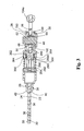
- FIGURE 3 is a cross-sectional view taken through the center of the mechanism 20.
- the anchor portions 30 mate with each other while the plate portions 28 of the upper and lower housing are spaced apart with the movable or sliding plate 26 positioned therebetween.
- Each housing portion 22, 24 includes a ramped transition surface 40 connecting the portions 28, 30.
- Each of the plate portions 28 is generally rectangular in shape defining a central opening 42.
- a first end 44 of each plate portion includes a central opening 46 through which is received a rivet 48.
- the rivet extends through an optional hardened steel bushing or sleeve 50, which assists in spacing the opposing plate portions apart and also serves as a mechanical stop to limit the outward extreme movement of the sliding plate 26.
- the end 44 includes two oblong openings 54a, 54b.
- Each of the plate portions further includes a first side 56 and a second side 58.
- Each plate portion additionally includes a second or opposing end 60 with a recessed portion (see numeral 62) recessed below the plane of the first and second side and first end.
- the first side 58 further includes a bent tab 64, which includes a forked end 66, which is bent over, or swaged, during final assembly to secure the housing portions 22, 24 together. Prior to bending over the end 66, the ends are received within corresponding openings 70 in the opposing upper and lower housing members, as well as within a corresponding spacer 180, which also serves as a guide.
- Each of the housing members 22, 24 includes an upraised bridge element 72, which extends above the plane of the first and second sides 56, 58 of the plate portion 28.
- Each bridge element includes a flat, extended surface 74, which includes an opening 76.
- Each of the bridge elements also includes a small notch 80 adjacent opening 42 and an oppositely positioned larger notch 82. The notches 80, 82 are used to capture facets of a sensor housing 90.
- the sliding plate 26 includes a first oval opening 100, situated near end 102. It is this end of the plate that is secured to a connector or connecting member 104, such as a length of seat belt webbing, that is in turn connected or secured to a conventional seat belt buckle, generally shown as 106. If a flexible seat belt webbing 104 is used as this connector or connecting member 104, then an insert 104a is inserted within opening 100 to protect the seat belt webbing 104 from any sharp edges that may exist about the opening 100. Positioned to the rear, that is, to the left in FIGURE 1, of the opening 100 is an oval opening 110.
- oval openings 112a, 112b Positioned on either side of the oval opening are rectangular or oval openings 112a, 112b, each of which has a length sufficient to not interfere with the motion of the sliding plate before it reaches its maximum excursion limited by the oval opening 110 and spacer 50.
- a larger opening Positioned rearward of the oval opening 110 is a larger opening, generally identified by numeral 120.
- This opening has a first part 122 and a second part 124.
- the width of this second part or opening 124 is narrower than the width of opening 122.
- sides 130, 132 of plate 26 are narrowed at numerals 134, 136.
- the slide or sliding plate 26 also includes projections 140, 142, which extend into opening 120.
- each of the inserts 150 includes a first surface 154 having a plurality of rectangular projections 156a, 156b, extending therefrom. Surface 154 of the lower insert 150 is not visible in FIGURE 1.
- Each of the projections 156a, 156b is received within a corresponding opening 54a, 54b in each of the housing members.
- the projections 156a, 156b are tightly received within the corresponding openings.
- Each of these inserts includes a second set of projections 158a, 158b extending from another surface 160.
- each two insert pieces 150 nest with each other to ensure they are aligned laterally and vertically as shown in FIGURE 4.
- Extending from surface 160 is a plurality of small tabs 161.
- each insert includes an oval-shaped slot 162 that is sized to prevent the insert (when it is in place on its respective housing member 22 or 24) from interfering with the rivet 48 and/or sleeve 50.
- Each of the projections 158a, 158b is received into the top and bottom of openings 112a, 112b of the plate 26.
- the projections 150a, 150b after insertion within the openings 112a, 112b, mate with each other and these inserts as well as the bushing maintain the spacing between the upper and lower housing members.
- the tabs 161 provide for a low-friction surface upon which the sliding plate 26 can slide and, further, the projections 158a, 158b laterally stabilize the plate 26.
- each of the housing members 22, 24 are spaced apart by the step on tab 64.
- a pair of spacers 180 assist in the spacing of the members 22, 24 but are designed not to take high loads, which are absorbed by each tab 64.
- Each spacer 180 includes each a longitudinal slot 182, which is respectively received on side 134, 136 of the plate 26.
- Each spacer includes a vertical slot 184, as seen in FIGURE 1.
- a corresponding tab 64 from each of the housing members 22, 24 is first received through opening 184 prior to being received within the corresponding opening 70 in the opposing housing member.
- the spacers 180 laterally stabilize the rear end of the plate 26 and also provide a low-friction surface upon which sides 134, 136 can slide.
- the sensor mechanism 20 includes a sensor housing 90.
- the housing 90 includes a cup-shaped body 200 having sidewalls 202 and a bottom 204. Extending from the bottom is a projection 206, which is received within opening 76 of the lower housing member 24.
- One of the walls 202 includes an upraised tab 210, which is received within groove 80 of the upper housing member.
- the sensor housing 90 further includes a rearwardly extending ledge 212, which includes on an upper surface thereof tabs 214a, 214b.
- the vertical surfaces 216a, 216b of tabs 214a, 214b are received within the groove 80 of the upper housing member 22 while the rear surface 216 of the extending ledge 212 rests against the side 218 of the depressed portion 62 of end 60 of the plate portion 28 of the upper housing member 22.
- a Hall effect sensor 230 is received within the sensor housing 90.
- the Hall effect sensor and its conditioning electronics 231 can provide an analog signal indicative of the spacing and hence the force applied to the sensor sensing mechanism. In other applications a continuous analog signal is not needed and a digital Hall effect sensor can be used.
- a digital Hall effect sensor is a conventional Hall effect sensor with a threshold established by associated electronics 231 such that the Hall effect sensor (and its electronics) will only generate an output signal if the applied force and hence the magnetic field exceeds the threshold level.
- the force sensing mechanism 20 further includes a spring subassembly 250, part of which holds a magnet 252.
- the spring assembly 250 includes a first support or plate 254 having two sets of laterally extending wings 256a, 256b and 257a, 257b. The sets of wings are spaced apart by a distance designated by numeral 258.
- the rear surface of plate 254 includes a recess 260 into which the magnet 252 is received.
- the front or opposite surface includes a circular projection 262 that is received within the inner diameter 264 of a compression spring 266. The circular projection 262 stabilizes the rear end of spring 266.
- Support 280 further includes a mechanical adjusting mechanism 350.
- the support mechanism 280 includes a projection 290, which is also part of the adjustment mechanism 350.
- the projection includes threads 354 and is sized to fit within the center space 264 of the spring 266.
- the adjustment mechanism 350 also includes a nut or wheel 360 having internal threads 362.
- the wheel 360 is mounted to and rotatable about the threaded projection 290.
- a flat side 364 of the nut or wheel 360 is adjacent end 266a of the spring 266. The nut translates relative to the spring 266 as the nut 360 is rotated on the threads of the projection 290.
- the supports or plates 254, 280 and the spring 266 are received within the major diameter opening 122 of plate 26.
- the projections provide positional guidance. Portions of these supports or plates 254, 280, spring 266 and wheel 360 extend into the openings 42 in the upper and lower housing members.
- the wheel 360 can extend beyond the housing members 22 or 24. The wheel 360 may be about even with the housing members 22, 24.
- the pairs of wings 256a, 256b envelop the inner wall 122 of the sliding plate 26.
- the front support 280 while being received within opening 122, actually rides upon the exterior surfaces of the upper and lower housing members.
- each set of wings 282a, 282b is sufficient to permit each wing of these respective sets of wings to slide on the top and bottom surfaces of the upper and lower housing members.
- the spring 266 is mounted, as mentioned above, such that end 264 is received about the circular boss 262, while its opposite end is received about the projection 290 on support 280.
- the nut 360 is rotated to a position that is clear of (or at least very lightly contacting) the end 266a of the spring 266. In this way the spring can be installed in a relaxed condition. Thereafter the nut 360 is rotated to a desired position, as discussed below, compressing the spring 266. As the spring 266 compresses, the slide 26 is biased rearwardly between the upper and lower housing members 22, 24.
- the spring 266 biases plate 254 rearwardly so that support or plate 254 bottoms against an adjacent wall of the sensor housing as more clearly shown in FIGURE 2.
- the spring 266 also biases support or plate 280 forwardly, or towards the right in FIGURE 1, which pushes the forward surface of the support or plate 280 against the surface 292 at the forward ends of openings 42.
- the spacing between the spring supports or plates 254, 280 will vary.
- the length of the spring 266 might be slightly different from a nominal length. If in a sensor that does not include an adjustment mechanism or feature 350 the spacing is too small or the spring length is too long, the pre-load force biasing the slide 26 and the housing members 22, 24 apart will vary from one sensor to the next. A different though similar result will occur if the above dimensions were reversed. The variation in part size may also create a dead zone of unknown size.
- the calibration process uses the adjustment mechanism 350 to provide a more uniformly operating sensor mechanism.
- the wheel 260 is initially placed at a non-contacting or lightly contacting location in which the spring 266 is at its relaxed length.
- the nut 360 can be pre-positioned based upon empirical data or it can simply be manually positioned apart from or near the spring. Thereafter, the nut 360 is rotated to compress the spring 266 until the bias force of the spring 266 is at a determinable level.
- the actual bias force is measured by introducing an accurate measuring device or calibration force sensor 380, such as between the supports 254, 280.
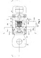
- the location of contacting or measurement arms 382a, 382b of the calibrating sensor 380 in relation to the supports 254, 280 is shown schematically in FIGURE 2.
- the wheel or nut 360 is rotated until the calibration sensor 380 reads about 0.5 Kilogram that is the desired bias force of the spring 266. This process insures that the housing members 22, 24 and the slide 26 will be uniformly biased from sensor to sensor and this process will also eliminate any dead zone.
- the calibration sensor is removed and used to calibrate another force sensor.
- the above method and apparatus compensates for the stack-up of tolerances due to the many parts used within the force sensor 20 and compensates for variability from sensor -to-sensor.
- the nut is fixed in place such as with a liquid thread lock.
- the slide 26 and housing will begin to move apart after the applied force differential exceeds the calibrated bias.
- the null output of the Hall effect sensor may be other than desired.
- the support 254, which carries the magnet 252 butts directly against the sensor housing 90 which houses the Hall effect sensor 230.
- the output of the Hall effect sensor 230 at its null position might vary from its preferred output level also due to the manufacturing tolerances of the mating parts.
- the effective output of the Hall effect sensor can be driven to the preferred level (including zero or another value) by analog or digital compensation.
- a bias voltage can be added (plus or minus) to the conditional electronics 231 to adjust the output signal to the preferred level.
- an offset digital value can be added to the Hall effect output in a related computer and control (storage) module.
- the plate moves outwardly relative to the housing members 22, 24 against the bias force of the spring 266 as the anchor portions 30 are held fixed.
- the spacing between the magnet 252 and the sensor 230 varies, thereby providing a measure of the displacement between the stationary sensor 230 and the moveable magnet 252, which is directly correlatable to the force applied by the seat belt.
- the size of the oval opening 110 and the adjacent openings 112a, 112b are sized such that, with exceptionally large forces, the sliding plate 26 is permitted to move outwardly until the inner surface 302 abuts a corresponding surface of the sleeve 50, which defines the maximum range of motion of the sliding plate.
Landscapes
- Engineering & Computer Science (AREA)
- Mechanical Engineering (AREA)
- Physics & Mathematics (AREA)
- General Physics & Mathematics (AREA)
- Chemical & Material Sciences (AREA)
- Analytical Chemistry (AREA)
- Automation & Control Theory (AREA)
- Textile Engineering (AREA)
- Force Measurement Appropriate To Specific Purposes (AREA)
- Air Bags (AREA)
Abstract
Description
- A sensor according to the invention set forth in the attached
claim 1 is useful for measuring the tensile force produced within a buckled-up seat belt system and more particularly the lap belt. - The present invention is an improved force sensing mechanism having a low dead zone, hysteresis and sliding friction, ease of assembly and reduced cost. The sensor includes a number of interconnected parts, some of which are relatively movable and mutually spring loaded. As a result of manufacturing tolerances the electrical output of the sensor, which follows its force-deflection characteristic, may include a dead zone or may display hysteresis. It is an object to provide a force sensor that includes a compensating feature to reduce or otherwise eliminate dead zone and/or hysteresis.
- Many other features of the invention will be clear from the following detailed description of the invention.
- FIGURE 1 is an exploded view of a force sensing mechanism in accordance with the present invention.
- FIGURE 2 is a plan view of the bottom of a force sensor.
- FIGURE 3 is a cross-sectional view through section 3-3 of FIGURE 2.
- FIGURE 4 is a cross-sectional view through section 4-4 of FIGURE 2.
- FIGURE 5 is a cross-sectional view through section 5-5 of FIGURE 2.
- FIGURE 6 is a cross-sectional view through section 6-6 of FIGURE 2.
- FIGURE 7 is a cross-sectional view through section 7-7 of FIGURE 2.
-
- FIGUREs 1-4 illustrate the major components of a seat belt force sensor or
sensing mechanism 20 which include: a housing having anupper housing member 22, alower housing member 24 and a slide or slidingmember 26. In the embodiment shown in FIGURE 1, thehousing members housing members slide 26 may be fabricated as stamped steel components, each having a coating to prevent corrosion and provide a uniform, smooth surface finish. Each of thehousing members plate portion 28 and ananchor portion 30. Theanchor portions 30 are secured to a structural component of the vehicle such as the floor or seat, generally indicated bynumeral 32 in FIGURE 1, through an anchor mechanism, which is also schematically shown bynumeral 34. These anchor mechanisms can, for example, include a cable attached at one cable end to theanchor portion 30 and at the other cable end to a structural section of the vehicle or the seat, to a seat belt pretensioner or alternatively, a fastener received through theopenings 36 in the anchor portions. The anchor can be designed to permit the force sensor to rotate or move in one or more directions. - FIGURE 3 is a cross-sectional view taken through the center of the
mechanism 20. In FIGURE 3 theanchor portions 30 mate with each other while theplate portions 28 of the upper and lower housing are spaced apart with the movable orsliding plate 26 positioned therebetween. Eachhousing portion transition surface 40 connecting theportions plate portions 28 is generally rectangular in shape defining acentral opening 42. Afirst end 44 of each plate portion includes acentral opening 46 through which is received arivet 48. The rivet extends through an optional hardened steel bushing orsleeve 50, which assists in spacing the opposing plate portions apart and also serves as a mechanical stop to limit the outward extreme movement of thesliding plate 26. If thebushing 50 is not used its function is performed by theshaft 52 of the rivet. Theend 44 includes twooblong openings first side 56 and asecond side 58. Each plate portion additionally includes a second oropposing end 60 with a recessed portion (see numeral 62) recessed below the plane of the first and second side and first end. Thefirst side 58 further includes abent tab 64, which includes a forkedend 66, which is bent over, or swaged, during final assembly to secure thehousing portions end 66, the ends are received withincorresponding openings 70 in the opposing upper and lower housing members, as well as within acorresponding spacer 180, which also serves as a guide. - Each of the
housing members upraised bridge element 72, which extends above the plane of the first andsecond sides plate portion 28. Each bridge element includes a flat, extendedsurface 74, which includes anopening 76. Each of the bridge elements also includes asmall notch 80adjacent opening 42 and an oppositely positionedlarger notch 82. Thenotches sensor housing 90. - The
sliding plate 26 includes a firstoval opening 100, situated nearend 102. It is this end of the plate that is secured to a connector or connectingmember 104, such as a length of seat belt webbing, that is in turn connected or secured to a conventional seat belt buckle, generally shown as 106. If a flexibleseat belt webbing 104 is used as this connector or connectingmember 104, then aninsert 104a is inserted within opening 100 to protect theseat belt webbing 104 from any sharp edges that may exist about theopening 100. Positioned to the rear, that is, to the left in FIGURE 1, of the opening 100 is anoval opening 110. Positioned on either side of the oval opening are rectangular oroval openings oval opening 110 andspacer 50. Positioned rearward of theoval opening 110 is a larger opening, generally identified bynumeral 120. This opening has afirst part 122 and asecond part 124. The width of this second part or opening 124 is narrower than the width of opening 122. It should be notedsides 130, 132 ofplate 26 are narrowed atnumerals sliding plate 26 also includesprojections - To prevent binding of the
sliding plate 26, the sensing mechanism orsensor 20 further utilizes two identically shaped inserts, both of which are shown bynumeral 150, which is also shown in FIGURE 4. Each of theinserts 150 includes afirst surface 154 having a plurality ofrectangular projections Surface 154 of thelower insert 150 is not visible in FIGURE 1. Each of theprojections corresponding opening projections projections surface 160. The projections of each twoinsert pieces 150 nest with each other to ensure they are aligned laterally and vertically as shown in FIGURE 4. Extending fromsurface 160 is a plurality ofsmall tabs 161. Additionally, each insert includes an oval-shaped slot 162 that is sized to prevent the insert (when it is in place on itsrespective housing member 22 or 24) from interfering with therivet 48 and/orsleeve 50. Each of theprojections openings plate 26. In FIGURE 3, the projections 150a, 150b, after insertion within theopenings tabs 161 provide for a low-friction surface upon which thesliding plate 26 can slide and, further, theprojections plate 26. - The
opposite ends 60 of each of thehousing members tab 64. A pair ofspacers 180 assist in the spacing of themembers tab 64. Eachspacer 180 includes each alongitudinal slot 182, which is respectively received onside plate 26. Each spacer includes avertical slot 184, as seen in FIGURE 1. During assembly, acorresponding tab 64 from each of thehousing members corresponding opening 70 in the opposing housing member. Thespacers 180 laterally stabilize the rear end of theplate 26 and also provide a low-friction surface upon whichsides sensor mechanism 20 includes asensor housing 90. Thehousing 90 includes a cup-shapedbody 200 havingsidewalls 202 and a bottom 204. Extending from the bottom is aprojection 206, which is received within opening 76 of thelower housing member 24. One of thewalls 202 includes anupraised tab 210, which is received withingroove 80 of the upper housing member. Thesensor housing 90 further includes arearwardly extending ledge 212, which includes on an uppersurface thereof tabs vertical surfaces tabs groove 80 of theupper housing member 22 while therear surface 216 of the extendingledge 212 rests against theside 218 of thedepressed portion 62 ofend 60 of theplate portion 28 of theupper housing member 22. In the illustrated embodiment aHall effect sensor 230 is received within thesensor housing 90. The Hall effect sensor and itsconditioning electronics 231 can provide an analog signal indicative of the spacing and hence the force applied to the sensor sensing mechanism. In other applications a continuous analog signal is not needed and a digital Hall effect sensor can be used. As used herein a digital Hall effect sensor is a conventional Hall effect sensor with a threshold established by associatedelectronics 231 such that the Hall effect sensor (and its electronics) will only generate an output signal if the applied force and hence the magnetic field exceeds the threshold level. - The
force sensing mechanism 20 further includes aspring subassembly 250, part of which holds amagnet 252. Thespring assembly 250 includes a first support orplate 254 having two sets of laterally extendingwings numeral 258. The rear surface ofplate 254 includes arecess 260 into which themagnet 252 is received. The front or opposite surface includes acircular projection 262 that is received within theinner diameter 264 of acompression spring 266. Thecircular projection 262 stabilizes the rear end ofspring 266. Positioned on the other side of spring of 266 is another support orplate 280 having two sets ofwings wings numeral 284.Support 280 further includes amechanical adjusting mechanism 350. Thesupport mechanism 280 includes aprojection 290, which is also part of theadjustment mechanism 350. The projection includesthreads 354 and is sized to fit within thecenter space 264 of thespring 266. Theadjustment mechanism 350 also includes a nut or wheel 360 havinginternal threads 362. The wheel 360 is mounted to and rotatable about the threadedprojection 290. Aflat side 364 of the nut or wheel 360 isadjacent end 266a of thespring 266. The nut translates relative to thespring 266 as the nut 360 is rotated on the threads of theprojection 290. - The supports or
plates spring 266 are received within the major diameter opening 122 ofplate 26. The projections provide positional guidance. Portions of these supports orplates spring 266 and wheel 360 extend into theopenings 42 in the upper and lower housing members. The wheel 360 can extend beyond thehousing members housing members plate 254 is received withinopening 122, the pairs ofwings inner wall 122 of the slidingplate 26. Thefront support 280, while being received withinopening 122, actually rides upon the exterior surfaces of the upper and lower housing members. The spacing 284 between each set ofwings spring 266 is mounted, as mentioned above, such thatend 264 is received about thecircular boss 262, while its opposite end is received about theprojection 290 onsupport 280. - During the initial assembly of the
spring 266 onto theprojection 290 the nut 360 is rotated to a position that is clear of (or at least very lightly contacting) theend 266a of thespring 266. In this way the spring can be installed in a relaxed condition. Thereafter the nut 360 is rotated to a desired position, as discussed below, compressing thespring 266. As thespring 266 compresses, theslide 26 is biased rearwardly between the upper andlower housing members - The
spring 266biases plate 254 rearwardly so that support orplate 254 bottoms against an adjacent wall of the sensor housing as more clearly shown in FIGURE 2. Thespring 266 also biases support orplate 280 forwardly, or towards the right in FIGURE 1, which pushes the forward surface of the support orplate 280 against thesurface 292 at the forward ends ofopenings 42. - Depending on at least the stack-up of tolerances of the various parts of the
sensor 20 the spacing between the spring supports orplates spring 266 might be slightly different from a nominal length. If in a sensor that does not include an adjustment mechanism or feature 350 the spacing is too small or the spring length is too long, the pre-load force biasing theslide 26 and thehousing members - The calibration process uses the
adjustment mechanism 350 to provide a more uniformly operating sensor mechanism. As mentioned, thewheel 260 is initially placed at a non-contacting or lightly contacting location in which thespring 266 is at its relaxed length. To speed assembly, the nut 360 can be pre-positioned based upon empirical data or it can simply be manually positioned apart from or near the spring. Thereafter, the nut 360 is rotated to compress thespring 266 until the bias force of thespring 266 is at a determinable level. During calibration of theforce sensor 22 the actual bias force is measured by introducing an accurate measuring device orcalibration force sensor 380, such as between thesupports measurement arms sensor 380 in relation to thesupports calibration sensor 380 reads about 0.5 Kilogram that is the desired bias force of thespring 266. This process insures that thehousing members slide 26 will be uniformly biased from sensor to sensor and this process will also eliminate any dead zone. After theforce sensor 20 is mechanically adjusted, the calibration sensor is removed and used to calibrate another force sensor. The above method and apparatus compensates for the stack-up of tolerances due to the many parts used within theforce sensor 20 and compensates for variability from sensor -to-sensor. After having calibrated the spring force the nut is fixed in place such as with a liquid thread lock. - The
slide 26 and housing will begin to move apart after the applied force differential exceeds the calibrated bias. - In some situations after mechanically calibrating the spring bias level, the null output of the Hall effect sensor may be other than desired. To more accurately set the null position, and as mentioned above the
support 254, which carries themagnet 252, butts directly against thesensor housing 90 which houses theHall effect sensor 230. The output of theHall effect sensor 230 at its null position might vary from its preferred output level also due to the manufacturing tolerances of the mating parts. If desired, the effective output of the Hall effect sensor can be driven to the preferred level (including zero or another value) by analog or digital compensation. For example, a bias voltage can be added (plus or minus) to theconditional electronics 231 to adjust the output signal to the preferred level. Alternately, an offset digital value can be added to the Hall effect output in a related computer and control (storage) module. - As a force is applied by the
seat belt 104 to end 102 of the slidingplate 26, the plate moves outwardly relative to thehousing members spring 266 as theanchor portions 30 are held fixed. As the force increases, the spacing between themagnet 252 and thesensor 230 varies, thereby providing a measure of the displacement between thestationary sensor 230 and themoveable magnet 252, which is directly correlatable to the force applied by the seat belt. The size of theoval opening 110 and theadjacent openings plate 26 is permitted to move outwardly until theinner surface 302 abuts a corresponding surface of thesleeve 50, which defines the maximum range of motion of the sliding plate.
Claims (8)
- A seat belt force-sensing mechanism (20) comprising:a housing (22, 24);a plate (26) slidably movable in relation to the housing;a magnetic sensor assembly including a magnet sensor (230) and a magnet (252) movable relative to one another in response to forces applied to the housing and to the plate;a spring assembly (250) having one end in operative engagement with the plate and another end in operative engagement with the housing to provide a bias force to resist movement of the plate; andan adjustment mechanism (350) located between the housing and the plate to enable the calibration of the magnet sensor.
- A seat belt force-sensing mechanism according to Claim 1 wherein the adjustment mechanism (350) includes a rotatable and translatable member (360) in contact with one end of a spring of the spring assembly (250) for adjusting the bias force to a preferred level.
- A seat belt force-sensing mechanism according to Claim 1 or 2 including a stop (50) for preventing movement of the plate (26) in one direction.
- A seat belt force-sensing mechanism according to Claim 3 wherein one stop (50) has a support plate (254) that butts up against a magnet sensor housing.
- A seat belt force-sensing mechanism according to Claim 4 wherein an end of the housing that receives the first and second spacers is secured by a rivet assembly and wherein the sliding plate includes an oblong opening (110) and the rivet assembly is received through the oblong opening (110), such that cooperation between the oblong opening and the rivet assembly provides at least one stop for restricting the sliding motion of the sliding plate (26).
- A seat belt force-sensing mechanism according to any of Claims 3 - 5 wherein the stop (50) is a mechanical stop in the form of a bushing or sleeve that assists in spacing the opposing plate portions apart to limit the outward extreme movement of the sliding plate (26).
- A seat belt force-sensing mechanism according to any of Claims 1 - 6 wherein the housing includes first (22) and second (24) housing members, both the first and second housing members including plate portions (28) that are spaced apart; and the plate (26) is positioned between the plate portions of the first and second housing members and is moveable; first and second spacers (150) are provided with the first spacer located between the first housing member and the plate and the second spacer located between the second housing member and the plate to space and stabilize the plate relative to the first and second housing members, the first and second spacers are located within corresponding apertures (112a, 1122b) of the sliding plate (26); third and fourth spacers (180) are positioned between the first and second housing members with both the third and fourth spacers including a longitudinal slot (182) therein to receive a corresponding portion of the plate, both the third and fourth spacers including slots (184) that are oriented generally perpendicular to the direction of movement of the sliding plate.
- A seat belt force-sensing mechanism according to any of Claims 1 - 7 wherein the magnet sensor (23) is a Hall effect sensor.
Applications Claiming Priority (2)
| Application Number | Priority Date | Filing Date | Title |
|---|---|---|---|
| US10/104,215 US6820458B2 (en) | 2000-05-04 | 2002-03-22 | Seat belt force sensor |
| US104215 | 2002-03-22 |
Publications (2)
| Publication Number | Publication Date |
|---|---|
| EP1350681A1 true EP1350681A1 (en) | 2003-10-08 |
| EP1350681B1 EP1350681B1 (en) | 2005-03-16 |
Family
ID=28040536
Family Applications (1)
| Application Number | Title | Priority Date | Filing Date |
|---|---|---|---|
| EP03001350A Expired - Lifetime EP1350681B1 (en) | 2002-03-22 | 2003-01-24 | Seat belt force sensor |
Country Status (3)
| Country | Link |
|---|---|
| US (1) | US6820458B2 (en) |
| EP (1) | EP1350681B1 (en) |
| DE (1) | DE60300381T2 (en) |
Families Citing this family (5)
| Publication number | Priority date | Publication date | Assignee | Title |
|---|---|---|---|---|
| DE10217227C1 (en) * | 2002-04-18 | 2003-05-22 | Autoliv Dev | Fixing arrangement for a seat belt lock comprises a holder having a T-shaped head with protruding arms, a connecting piece having abutments lying opposite the arms |
| US7347452B2 (en) * | 2003-04-23 | 2008-03-25 | Delphi Technologies, Inc. | Tension sensing assembly |
| US9045105B2 (en) * | 2011-11-18 | 2015-06-02 | BuckleRight, LLC | Seatbelt buckle position holders |
| US9164003B2 (en) | 2012-10-11 | 2015-10-20 | Honeywell International Inc. | Force sensor with mechanical over-force transfer mechanism |
| SE2050035A1 (en) * | 2020-01-16 | 2021-07-17 | Holmbergs Safety System Holding Ab | Belt buckle for a safety belt in a child restraint system |
Citations (3)
| Publication number | Priority date | Publication date | Assignee | Title |
|---|---|---|---|---|
| US5535630A (en) * | 1994-03-25 | 1996-07-16 | Smc Kabushiki Kaisha | Shock load sensor |
| US6205868B1 (en) * | 1997-12-10 | 2001-03-27 | Automotive Systems Lab | Hall-effect seat belt tension sensor |
| WO2001083275A2 (en) * | 2000-05-04 | 2001-11-08 | Breed Automotive Technology, Inc. | Seat belt tension sensor |
Family Cites Families (10)
| Publication number | Priority date | Publication date | Assignee | Title |
|---|---|---|---|---|
| US4667514A (en) * | 1985-05-01 | 1987-05-26 | Baer John S | Parameter sensors and monitors |
| US5839174A (en) * | 1997-06-13 | 1998-11-24 | Breed Automotive Technology, Inc. | Seat belt buckle |
| US6081759A (en) * | 1998-04-24 | 2000-06-27 | Breed Automotive Technology, Inc. | Seat belt tension sensor |
| US5996421A (en) * | 1998-04-24 | 1999-12-07 | Breed Automotive Technology, Inc. | Seat belt tension sensor employing flexible potentiometer |
| US6255609B1 (en) * | 2000-06-26 | 2001-07-03 | Predator Systems, Inc. | High pressure resistant, low pressure actuating sensors |
| US6508114B2 (en) * | 2000-11-29 | 2003-01-21 | Casco Products Corporation | Webbing tension sensor |
| US6640648B2 (en) * | 2001-02-07 | 2003-11-04 | Breed Automotive Technology, Inc. | Seat belt force sensor |
| US6520032B2 (en) * | 2001-03-27 | 2003-02-18 | Trw Vehicle Safety Systems Inc. | Seat belt tension sensing apparatus |
| US6578432B2 (en) * | 2001-06-19 | 2003-06-17 | Cts Corporation | Seat belt tension sensor |
| US6776056B2 (en) * | 2001-08-06 | 2004-08-17 | Cts Corporation | Seat belt tension sensor |
-
2002
- 2002-03-22 US US10/104,215 patent/US6820458B2/en not_active Expired - Lifetime
-
2003
- 2003-01-24 EP EP03001350A patent/EP1350681B1/en not_active Expired - Lifetime
- 2003-01-24 DE DE60300381T patent/DE60300381T2/en not_active Expired - Lifetime
Patent Citations (3)
| Publication number | Priority date | Publication date | Assignee | Title |
|---|---|---|---|---|
| US5535630A (en) * | 1994-03-25 | 1996-07-16 | Smc Kabushiki Kaisha | Shock load sensor |
| US6205868B1 (en) * | 1997-12-10 | 2001-03-27 | Automotive Systems Lab | Hall-effect seat belt tension sensor |
| WO2001083275A2 (en) * | 2000-05-04 | 2001-11-08 | Breed Automotive Technology, Inc. | Seat belt tension sensor |
Also Published As
| Publication number | Publication date |
|---|---|
| DE60300381D1 (en) | 2005-04-21 |
| EP1350681B1 (en) | 2005-03-16 |
| US6820458B2 (en) | 2004-11-23 |
| DE60300381T2 (en) | 2006-04-13 |
| US20030177811A1 (en) | 2003-09-25 |
Similar Documents
| Publication | Publication Date | Title |
|---|---|---|
| KR101057967B1 (en) | Car acceleration pedal | |
| US6857326B2 (en) | Device for measuring force acting upon a seat belt | |
| US5207116A (en) | Cable core length adjuster mechanism | |
| US4805467A (en) | Force recording seat belt assembly | |
| US5839174A (en) | Seat belt buckle | |
| US6640648B2 (en) | Seat belt force sensor | |
| EP1350681B1 (en) | Seat belt force sensor | |
| US20120258620A1 (en) | Electrical connector configured to connect to a flex cable | |
| US5163338A (en) | Cable core length adjuster mechanism | |
| US6796192B2 (en) | Pass through seat restraint tension sensing assembly | |
| US11906039B2 (en) | Selector device for a user input for shifting a vehicle gearbox, and gearbox system for a vehicle | |
| US12291900B2 (en) | Door handle apparatus | |
| US20100258424A1 (en) | Slide switch structure and power seat switch using the same | |
| EP1654137B1 (en) | Pedal mechanism for motor vehicles | |
| EP2987686B1 (en) | Buckle for seatbelt device | |
| US7000488B2 (en) | Force-sensing unit for measuring a belt tensile force acting on a seatbelt lock | |
| WO2009086889A2 (en) | Linear sensor | |
| CN112703379A (en) | Device for measuring the temperature in the interior of a vehicle | |
| US7021162B2 (en) | Belt force measuring device | |
| US4257286A (en) | Precision driving apparatus | |
| EP2250466A2 (en) | Linear sensor | |
| JP2836672B2 (en) | Acceleration detector | |
| US20080295632A1 (en) | Shift Module | |
| CN1989397A (en) | Force sensing device | |
| US6374682B1 (en) | Force-measuring apparatus, particularly a weighing cell I |
Legal Events
| Date | Code | Title | Description |
|---|---|---|---|
| PUAI | Public reference made under article 153(3) epc to a published international application that has entered the european phase |
Free format text: ORIGINAL CODE: 0009012 |
|
| 17P | Request for examination filed |
Effective date: 20030805 |
|
| AK | Designated contracting states |
Kind code of ref document: A1 Designated state(s): AT BE BG CH CY CZ DE DK EE ES FI FR GB GR HU IE IT LI LU MC NL PT SE SI SK TR |
|
| AX | Request for extension of the european patent |
Extension state: AL LT LV MK RO |
|
| 17Q | First examination report despatched |
Effective date: 20040105 |
|
| AKX | Designation fees paid |
Designated state(s): DE FR GB IT |
|
| GRAP | Despatch of communication of intention to grant a patent |
Free format text: ORIGINAL CODE: EPIDOSNIGR1 |
|
| RAP1 | Party data changed (applicant data changed or rights of an application transferred) |
Owner name: KEY SAFETY SYSTEMS, INC. |
|
| GRAS | Grant fee paid |
Free format text: ORIGINAL CODE: EPIDOSNIGR3 |
|
| GRAA | (expected) grant |
Free format text: ORIGINAL CODE: 0009210 |
|
| AK | Designated contracting states |
Kind code of ref document: B1 Designated state(s): DE FR GB IT |
|
| REG | Reference to a national code |
Ref country code: GB Ref legal event code: FG4D |
|
| REG | Reference to a national code |
Ref country code: IE Ref legal event code: FG4D |
|
| REF | Corresponds to: |
Ref document number: 60300381 Country of ref document: DE Date of ref document: 20050421 Kind code of ref document: P |
|
| PLBE | No opposition filed within time limit |
Free format text: ORIGINAL CODE: 0009261 |
|
| STAA | Information on the status of an ep patent application or granted ep patent |
Free format text: STATUS: NO OPPOSITION FILED WITHIN TIME LIMIT |
|
| 26N | No opposition filed |
Effective date: 20051219 |
|
| ET | Fr: translation filed | ||
| PGFP | Annual fee paid to national office [announced via postgrant information from national office to epo] |
Ref country code: FR Payment date: 20101221 Year of fee payment: 9 |
|
| PGFP | Annual fee paid to national office [announced via postgrant information from national office to epo] |
Ref country code: GB Payment date: 20101215 Year of fee payment: 9 |
|
| PGFP | Annual fee paid to national office [announced via postgrant information from national office to epo] |
Ref country code: IT Payment date: 20110126 Year of fee payment: 9 |
|
| GBPC | Gb: european patent ceased through non-payment of renewal fee |
Effective date: 20120124 |
|
| REG | Reference to a national code |
Ref country code: FR Ref legal event code: ST Effective date: 20120928 |
|
| PG25 | Lapsed in a contracting state [announced via postgrant information from national office to epo] |
Ref country code: GB Free format text: LAPSE BECAUSE OF NON-PAYMENT OF DUE FEES Effective date: 20120124 |
|
| PG25 | Lapsed in a contracting state [announced via postgrant information from national office to epo] |
Ref country code: IT Free format text: LAPSE BECAUSE OF NON-PAYMENT OF DUE FEES Effective date: 20120124 |
|
| PG25 | Lapsed in a contracting state [announced via postgrant information from national office to epo] |
Ref country code: FR Free format text: LAPSE BECAUSE OF NON-PAYMENT OF DUE FEES Effective date: 20120131 |
|
| PGFP | Annual fee paid to national office [announced via postgrant information from national office to epo] |
Ref country code: DE Payment date: 20180109 Year of fee payment: 16 |
|
| REG | Reference to a national code |
Ref country code: DE Ref legal event code: R119 Ref document number: 60300381 Country of ref document: DE |
|
| PG25 | Lapsed in a contracting state [announced via postgrant information from national office to epo] |
Ref country code: DE Free format text: LAPSE BECAUSE OF NON-PAYMENT OF DUE FEES Effective date: 20190801 |