EP1350528A1 - Needle-disposable insert for sharps disposal - Google Patents
Needle-disposable insert for sharps disposal Download PDFInfo
- Publication number
- EP1350528A1 EP1350528A1 EP03002864A EP03002864A EP1350528A1 EP 1350528 A1 EP1350528 A1 EP 1350528A1 EP 03002864 A EP03002864 A EP 03002864A EP 03002864 A EP03002864 A EP 03002864A EP 1350528 A1 EP1350528 A1 EP 1350528A1
- Authority
- EP
- European Patent Office
- Prior art keywords
- needle
- reset
- release
- holder
- disposal
- Prior art date
- Legal status (The legal status is an assumption and is not a legal conclusion. Google has not performed a legal analysis and makes no representation as to the accuracy of the status listed.)
- Withdrawn
Links
Images




Classifications
-
- A—HUMAN NECESSITIES
- A61—MEDICAL OR VETERINARY SCIENCE; HYGIENE
- A61B—DIAGNOSIS; SURGERY; IDENTIFICATION
- A61B50/00—Containers, covers, furniture or holders specially adapted for surgical or diagnostic appliances or instruments, e.g. sterile covers
- A61B50/30—Containers specially adapted for packaging, protecting, dispensing, collecting or disposing of surgical or diagnostic appliances or instruments
- A61B50/36—Containers specially adapted for packaging, protecting, dispensing, collecting or disposing of surgical or diagnostic appliances or instruments for collecting or disposing of used articles
- A61B50/362—Containers specially adapted for packaging, protecting, dispensing, collecting or disposing of surgical or diagnostic appliances or instruments for collecting or disposing of used articles for sharps
-
- A—HUMAN NECESSITIES
- A61—MEDICAL OR VETERINARY SCIENCE; HYGIENE
- A61B—DIAGNOSIS; SURGERY; IDENTIFICATION
- A61B50/00—Containers, covers, furniture or holders specially adapted for surgical or diagnostic appliances or instruments, e.g. sterile covers
- A61B2050/005—Containers, covers, furniture or holders specially adapted for surgical or diagnostic appliances or instruments, e.g. sterile covers with a lid or cover
- A61B2050/0051—Containers, covers, furniture or holders specially adapted for surgical or diagnostic appliances or instruments, e.g. sterile covers with a lid or cover closable by rotation
- A61B2050/0056—Containers, covers, furniture or holders specially adapted for surgical or diagnostic appliances or instruments, e.g. sterile covers with a lid or cover closable by rotation about a lateral axis in the lid plane
-
- A—HUMAN NECESSITIES
- A61—MEDICAL OR VETERINARY SCIENCE; HYGIENE
- A61M—DEVICES FOR INTRODUCING MEDIA INTO, OR ONTO, THE BODY; DEVICES FOR TRANSDUCING BODY MEDIA OR FOR TAKING MEDIA FROM THE BODY; DEVICES FOR PRODUCING OR ENDING SLEEP OR STUPOR
- A61M5/00—Devices for bringing media into the body in a subcutaneous, intra-vascular or intramuscular way; Accessories therefor, e.g. filling or cleaning devices, arm rests
- A61M5/178—Syringes
- A61M5/31—Details
- A61M5/32—Needles; Details of needles pertaining to their connection with syringe or hub; Accessories for bringing the needle into, or holding the needle on, the body; Devices for protection of needles
- A61M5/3205—Apparatus for removing or disposing of used needles or syringes, e.g. containers; Means for protection against accidental injuries from used needles
- A61M2005/3206—Needle or needle hub disconnecting devices forming part of or being attached to the hub or syringe body
-
- A—HUMAN NECESSITIES
- A61—MEDICAL OR VETERINARY SCIENCE; HYGIENE
- A61M—DEVICES FOR INTRODUCING MEDIA INTO, OR ONTO, THE BODY; DEVICES FOR TRANSDUCING BODY MEDIA OR FOR TAKING MEDIA FROM THE BODY; DEVICES FOR PRODUCING OR ENDING SLEEP OR STUPOR
- A61M5/00—Devices for bringing media into the body in a subcutaneous, intra-vascular or intramuscular way; Accessories therefor, e.g. filling or cleaning devices, arm rests
- A61M5/178—Syringes
- A61M5/31—Details
- A61M5/32—Needles; Details of needles pertaining to their connection with syringe or hub; Accessories for bringing the needle into, or holding the needle on, the body; Devices for protection of needles
- A61M5/3205—Apparatus for removing or disposing of used needles or syringes, e.g. containers; Means for protection against accidental injuries from used needles
Definitions
- the present invention relates to an infectious waste container system for fluid collection needles. More particularly, the invention relates to an improvement in the disposal of needles from a needle holder into a sharps needle disposal container.
- Fluid collection needles are used for sampling fluid, such as blood from a patient for tests or blood sedimentation.
- the needles usually are affixed to a needle holder by screw engagement.
- a used needle is separated from a holder for discard by covering the used needle with a protector and disengaging the male screw on the hub of the needle from the female screw of the needle holder to separate the needle, and the protector from the holder.
- the removed needle, covered by the protector then is put into a suitable container.
- needle holders which are designed to allow the operator to remove the used blood collection needle without handling it with fingers.
- These needle holders specifically are designed to be easily operable and to be used in combination with a needle having a specific configuration including a concave or convex portion.
- these needle holders cannot be used in combination with conventional screw mount type needles.
- the easily operable needle holder includes a cylindrical holder body with first and second ends.
- the cylindrical holder body has a needle fixing means at the first end of the cylinder.
- the needle fixing means includes a fixed member and first and second sliding members that are slidable along a wall at the first end of the cylindrical body.
- the fixed member is configured to grip one circumferential half of a needle hub
- the first sliding member is configured to grip the opposed circumferential half of the needle hub.
- the first sliding member is movable between a closed position where the needle hub is gripped between the fixed member and the first sliding member and an open position where the needle hub can pass between the fixed member and the first sliding member.
- the second sliding member is effectively an actuator that can move the first sliding member from the closed position to the open position.
- the needle can be removed from the above-described holder by exerting digital pressure on the second sliding member to slide the first sliding member away from the fixed member. This disengages the needle from the holder, and the needle falls gravitationally into a suitable sharps container located just below the needle holder.
- inserts fitted into the container have been developed to activate the release mechanism on the holder for disengaging the needle from the holder.
- Such an insert typically includes a release mechanism which contacts the first sliding member, thereby sliding the first sliding member toward the second sliding member, and disengaging the needle from the holder.
- the present invention provides an improved needle disposal insert for a disposal container.
- the needle disposal insert includes a cylindrical member having a cylindrical wall including atop end and a bottom end.
- First and second recesses are diametrically opposed on the cylindrical wall.
- the first recess includes a notched portion for disengaging a needle from a needle holder, and the second recess includes an indented portion including a restart means for returning the needle holder to a closed position.
- the restart means in the second recess may comprise a sloped wall sloping radially outwardly from the top end of the insert for engaging a restart mechanism on a needle holder.
- the present invention also provides an infectious waste container system that includes a disposal container, a needle holder, and a needle disposal insert mounted to or formed with the disposal container for interaction with the needle holder.
- the needle disposal insert comprises a cylindrical member having a cylindrical wall with top and bottom ends and having first and second diametrically opposed recess on the cylindrical wall.
- the first recess includes a notched portion for disengaging a needle from a needle collection holder.
- the second recess includes an indented portion with a restart means for restarting the needle holder to a closed position.
- the restart means in the second recess is a sloped wall sloping radially out from the top end of the insert and engages a restart mechanism on a needle holder.
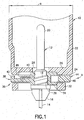
- FIG. 1 is a longitudinal cross-sectional view of a needle holder and needle assembly.
- FIG. 2 is a longitudinal cross-sectional view of the needle holder in FIG. 1 after release of the needle assembly.
- FIG 3. is a perspective view of a needle disposal insert in accordance with the invention.
- FIG. 4 is a top plan view of the needle disposal insert.
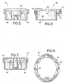
- FIG. 5 is a front elevational view of the needle disposal insert.
- FIG. 6 is a side elevational view of the needle disposal insert.
- FIG. 7 is a rear elevational view of the needle disposal insert.
- FIG. 8 is a bottom plan view of the needle disposal insert.
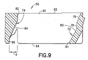
- FIG. 9 is a cross-sectional view taken along line 9-9 in FIG. 4.
- FIG. 10 is a perspective view of a disposal container that includes the disposal insert of FIGS. 3-9.
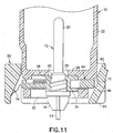
- FIG. 11 is a longitudinal cross-sectional view of the needle holder and needle assembly of FIG. 1 during an initial stage of insertion into the needle disposal insert of FIGS. 3-9.
- FIG. 12 is a cross-sectional view similar to FIG. 11, but showing the needle holder inserted sufficiently into the needle disposal insert.
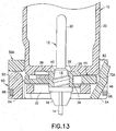
- FIG. 13 is a cross-sectional view similar to FIG. 11, but showing an alternate needle disposal insert.
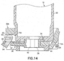
- FIG. 14 is a cross-sectional view similar to FIG. 12, but showing the alternate needle disposal insert.
- Needle assembly 12 includes a needle cannula 14 with an intravenous end facing downwardly in FIG. 1 and a non-patient end facing upwardly in FIG. 1. Needle cannula 14 is securely and permanently mounted in a plastic hub 16. Hub 16 includes an array of external threads 18 that extends from an intermediate location on hub 16 toward the non-patient end of needle cannula 14. An elastomeric sheath 20 covers the non-patient end of needle cannula 14 and functions as a valve to permit multiple samples of a bodily fluid to be collected.
- Needle holder 10 includes a tubular sidewall 22 with a widely open proximal end (not shown) and a distal end 24 .
- An end wall 26 extends transversely across distal end 24 of tubular sidewall 22 and includes a central aperture 28.
- Aperture 28 defines a cross-sectional dimension that exceeds the maximum cross-sectional dimension of needle assembly 12 .
- Needle gripping assembly 30 is secured to end wall 26 of holder 10 .
- Needle gripping assembly 30 includes a housing 32 and a fixed jaw 34 , both of which are substantially immovably mounted to end wall 26.
- Fixed jaw 34 includes a semi-cylindrical concave inner surface 36 that is concentric with aperture 28 in end wall 26 and that is dimensioned to engage the threaded portion of hub 16.
- Needle gripping assembly 30 further includes a movable jaw 38 that is movable toward and away from fixed jaw 34.
- Movable jaw 38 is characterized by a generally semi-cylindrical concave surface 40 that is configured to engage the threaded portion of hub 16 when movable jaw 38 is moved toward fixed jaw 34, as shown in FIG. 1.
- Movable jaw 38 further includes a flange 42 spaced radially outwardly from concave gripping surface 40 .
- An actuating member 44 that is movable parallel to movable jaw 38 , and has an externally accessible first actuating surface 46 that is diametrically opposite concave gripping surface 40 of the movable jaw 38.
- Actuating member 44 further includes a second actuating surface 48 that faces flange 42 of movable jaw 38.
- sidewall 22 of needle holder 10 defines an outside diameter "a" at locations near end wall 26 .
- the outside cross-sectional dimension between the first actuating surface 46 of actuator 40 and flange 42 on movable jaw 38 is only slightly less than outside diameter "a”.
- the outside surface of flange 42 of movable jaw 38 is offset from the outer surface of tubular sidewall 22 on needle holder 10 by a distance "b" when movable jaw 38 is in the open position.
- FIG. 1 depicts a condition where movable jaw 38 is moved toward fixed jaw 34.
- threads 18 of hub 16 can be secured between concave gripping surfaces 36 and 40 for holding needle assembly 12 in needle holder 10.
- the non-patient end of needle assembly 12 projects into needle holder 10 .
- Radially inward forces can be exerted on first actuating surface 46 of actuator 44 to move actuator 44 in the direction of arrow A in FIG. 1. This movement will cause actuator 44 to move movable jaw 38 away from fixed jaw 34 and into the condition shown in FIG. 2.
- the cross-section defined by semi-cylindrical concave gripping surfaces 36 and 40 exceeds the cross-sectional dimensions of threaded portion of needle hub 16.
- Needle holder 10 can be reset for accommodating a new needle assembly by exerting radially inward forces on flange 42 of movable jaw 38 . These forces urge movable jaw 38 into actuator 44 , and hence reset both movable jaw 38 and actuator 44 into a position for threadedly accommodating a new needle assembly 12.
- Some needle holders as described above and illustrated in FIGS. 1 and 2 are intended to be actuated and reset by a thumb or forefinger. However, as explained above, there are advantages to minimizing manual activity required near the needle assembly.
- Other needle holders are used with an actuating ring.
- the actuator ring typically is mounted in an opening in a sharps disposal container.
- the needle holder and needle assembly are urged into the actuator ring.
- the actuator ring is configured to urge the actuator in the direction of arrow A for moving a movable jaw and releasing the needle cannula.
- a needle disposal insert in accordance with the subject invention is identified by the numeral 50 in FIGS. 3-12 and is intended for use with needle holder 10 and needle assembly 12. Needle disposal insert 50 further is usable with a sharps disposal container, such as sharps disposal container 52 illustrated in FIG. 10. Sharps disposal container 52 includes an open-topped receptacle 54 and a lid 56 snapped into secure engagement with the open top of receptacle 54 . Lid 56 is characterized by an opening 58 and a hinged cover 60 .
- Needle disposal insert 50 is a generally tubular structure unitarily molded from a rigid plastic material and having a top end 62, a bottom end 64, an inner surface 66 and an outer surface 68 .
- Outer surface 68 of needle disposal insert 60 is configured for insertion into opening 58 in lid 56 of sharps disposal container 52. Additionally, portions of outer surface 68 near top end 62 are characterized by opposed upwardly and downwardly facing lock surfaces 70 to permit snapped engagement of needle disposal insert 50 with portions of lid 56 adjacent opening 58.
- inner surface 66 of needle disposal insert 50 is approximately cylindrical. However, inner surface 66 is characterized by a release section, identified generally by the numeral 72 , and a reset section, identified generally by the numeral 74 .
- Release section 72 is characterized by an upper slanted surface 76 that extends downwardly and inwardly from top end 62 of needle disposal insert 50 for approximately one third the length of needle disposal insert 50.
- Release section 72 is characterized further by a vertical guide surface 78 aligned substantially parallel to the axis of tubular needle disposal insert 50 from the lower end of upper slanted surface 76 to a location approximately midway between top and bottom ends 62 and 64 .
- Release section 72 is characterized further by a lower slanted surface 80 that extends down from the lower end of vertical guide surface 78.
- a lower vertical surface 81 extends from the bottom end of lower slanted surface 80.
- Lower slanted surface 80 is aligned to the axis of needle disposal insert 50 at an angle of between 20° and 40°, and preferably about 28° and continues to bottom end 64 of needle disposal insert 50.
- Reset section 74 is characterized by an upper vertical surface 82 that extends down from top end 62 approximately one fourth the distance to bottom end 64 .
- the reset section is further characterized by a sloped reset surface 84 that extends down and out from the bottom end of upper vertical surface 82. Sloped reset surface 84 extends for a distance at least equal to approximately one half the distance between top and bottom ends 62 and 64 .
- Reset section 74 is characterized further by a lower vertical surface 86 that extends from the bottom end of sloped reset section 84 to the bottom end 64 of needle disposal insert 50. Slopped reset surface 84 is aligned to the axis of needle disposal insert 50 at an angle of between about 20° and 40°, and preferably about 24°. Thus, surfaces 80 and 84 may be approximately parallel.
- the effective diameter that is formed between vertical guide surface 78 of release section 72 and a downward extension of upper vertical surface 82 of reset section 74 is only slightly greater than the outside diameter "a" of portions of needle holder 10 near end wall 26. It follows that the effective diameter that is formed between the downward extension of upper vertical surface 82 and the lower sloped surface 80 on release section 72 at locations closer to bottom end 64 of needle disposal insert 50 becomes continuously smaller than the outside diameter "a" of needle holder 10.
- the radial offset between upper and lower vertical surfaces 82 and 86 on reset section 74 is identified by dimension "d" which is slightly greater than the radial offset "b" between the outer surface of flange 42 on movable jaw 38 and the outer circumferential surface of tubular sidewall 22 on holder 10, as shown in FIG. 2.
- Needle disposal insert 50 is mounted in opening 58 in lid 56 of sharps disposal container 52 so that top end 62 of needle disposal insert 50 is substantially flush with or slightly above the top surface of lid 56. Thus, bottom end 64 of needle disposal insert 50 projects into sharps disposal container 52. Needle disposal insert 50 is employed as shown in FIGS. 11 and 12 by initially urging the assembly of needle holder 10 and used needle assembly 12 within the inner circumferential surface 62 of needle disposal insert 50. Thus, the intravenous end of needle cannula 14 projects down through needle disposal insert 50 . Needle holder 10 is rotationally aligned so that first actuating surface 44 substantially registers with release section 72.
- Needle holder 10 then is urged down so that outer circumferential surface regions of sidewall 22 slide against vertical guide surface 78 of release section 72 and upper vertical surface 82 of reset section 74 . Further downward movement of needle holder 10 urges actuating surface 46 of actuator 44 into sliding engagement with lower sloped surface 80 of release section 72. However, the continued slidable engagement of sidewall 22 with vertical surfaces 78 and 82 prevents the entire needle holder 10 from translating. Thus, actuator 44 moves transversely relative to needle holder 10 and causes movable jaw 38 to translate transversely into the open position shown in FIG. 12. This translation of movable jaw 38 is permitted by the downwardly and outwardly sloped reset surface 84 of reset section 74 .
- the offset "d" between upper and lower vertical surfaces 82 and 84 at opposite ends of sloped surface 84 is sufficient to permit the full range of translation of movable jaw 38 .
- used needle assembly 12 falls gravitationally into sharps receptacle 52.
- the user may then pull needle holder 10 up and away from needle disposal insert 50 .
- the vertical surfaces 78 and 82 continue to hold tubular sidewall 22 of needle holder 10 in its original alignment.
- the outer surface of flange 42 on movable jaw 38 will slide against the upwardly and inwardly sloped surface 84 of reset section 74 .
- movable jaw 38 will be forced to translate radially inwardly and back into the closed position from FIG. 11.
- holder 10 is arranged to threadedly receive a new needle assembly 12 without any resetting by the user. Consequently, correct positioning of fixed jaw 34 and movable jaw 38 is assured by the mere separation of needle holder 10 from needle disposal insert 50.
- the illustrated embodiments relate to a needle disposal insert with rigidly fixed release and reset sections.
- a needle disposal insert with release and/or reset sections that are spring driven, spring assisted or otherwise biased for movement in the direction of the slope to help move the movable jaw. Thus, less force will be required by the user.
- FIGS. 13 and 14 an alternate needle disposal insert is illustrated in FIGS. 13 and 14 and is identified generally by the numeral 50A.
- Needle disposal insert 50A is used with a receptacle 52 identical to the receptacle 52 described above and illustrated in FIG. 10. Additionally, needle disposal insert 50A is used with a needle holder 10 identical to needle holder 10 described and illustrated above. Insert 50A is structurally and functionally very similar to insert 50 described and illustrated above. More particularly, insert 50A includes a release section 72A identical to the release section 72 described and illustrated with respect to the first embodiment of needle disposal insert 50. However, needle disposal insert 50A includes a reset section 74A that is movable for actively assisting in the reset of needle gripping assembly 30 .
- reset section 74A includes a reset wall 90 with opposite top and bottom ends 92 and 94.
- Top end 92 of reset wall 90 is connected pivotally to the remainder of needle disposal insert 50A.
- bottom end 94 can pivot inwardly and outwardly relative to needle disposal insert 50A.
- Needle disposal insert 50A further includes biasing means 96 for urging reset wall 90 inwardly.
- Biasing means 96 is illustrated as being an elastic member that extends circumferentially around needle disposal insert 52 . However, other biasing means may be employed, such as a biasing means unitarily incorporated into the hinge connection or a radially aligned spring for exerting radially inward forces on reset wall 90 .
- Biasing means 96 normally urges reset wall 90 into a radially inner position as shown in FIG. 13. However, forces generated by the downward movement of needle holder 10 into needle disposal insert 50A will cause lower end 94 of reset wall 90 to pivot out and against forces exerted by biasing means 96.
- the outward pivoted alignment of reset wall 90 is similar to the alignment of sloped surface 84 on reset section 74 in needle disposal insert 50 of FIG. 9. Thus, reset wall 90 will perform in a similar manner to reset section 74 of needle disposal insert 50.
- biasing means 96 will urge lower portions of reset wall 90 in a radially inward direction, thereby assisting in the reset of movable jaw 38.
Landscapes
- Health & Medical Sciences (AREA)
- Life Sciences & Earth Sciences (AREA)
- Surgery (AREA)
- Heart & Thoracic Surgery (AREA)
- Engineering & Computer Science (AREA)
- Biomedical Technology (AREA)
- Nuclear Medicine, Radiotherapy & Molecular Imaging (AREA)
- Medical Informatics (AREA)
- Molecular Biology (AREA)
- Animal Behavior & Ethology (AREA)
- General Health & Medical Sciences (AREA)
- Public Health (AREA)
- Veterinary Medicine (AREA)
- Accommodation For Nursing Or Treatment Tables (AREA)
Abstract
Description
- The present invention relates to an infectious waste container system for fluid collection needles. More particularly, the invention relates to an improvement in the disposal of needles from a needle holder into a sharps needle disposal container.
- Fluid collection needles are used for sampling fluid, such as blood from a patient for tests or blood sedimentation. The needles usually are affixed to a needle holder by screw engagement. A used needle is separated from a holder for discard by covering the used needle with a protector and disengaging the male screw on the hub of the needle from the female screw of the needle holder to separate the needle, and the protector from the holder. The removed needle, covered by the protector, then is put into a suitable container.
- In this process however, there is a risk of an accidental needle stick with a finger or a palm of the hand at the time of covering the blood collection needle with the protector. There are obvious biohazards associated with such a procedure for the operator, i.e., infection with viruses, such as HIV or hepatitis in the worse case.
- To solve this problem, devices have been developed, including various needle holders, which are designed to allow the operator to remove the used blood collection needle without handling it with fingers. These needle holders specifically are designed to be easily operable and to be used in combination with a needle having a specific configuration including a concave or convex portion. However, due to the specific configuration, these needle holders cannot be used in combination with conventional screw mount type needles.
- To solve the problem of assembling the needle to the needle holder, more sophisticated needle holders have been developed including an easily operable needle holder. The easily operable needle holder includes a cylindrical holder body with first and second ends. The cylindrical holder body has a needle fixing means at the first end of the cylinder. The needle fixing means includes a fixed member and first and second sliding members that are slidable along a wall at the first end of the cylindrical body. The fixed member is configured to grip one circumferential half of a needle hub, and the first sliding member is configured to grip the opposed circumferential half of the needle hub. The first sliding member is movable between a closed position where the needle hub is gripped between the fixed member and the first sliding member and an open position where the needle hub can pass between the fixed member and the first sliding member. The second sliding member is effectively an actuator that can move the first sliding member from the closed position to the open position. This needle holder makes it possible to fix the needle releasably to the holder and may be used in combination with screw-mount type blood collection needles.
- The needle can be removed from the above-described holder by exerting digital pressure on the second sliding member to slide the first sliding member away from the fixed member. This disengages the needle from the holder, and the needle falls gravitationally into a suitable sharps container located just below the needle holder. To facilitate the depositing of the needles from the holder into such disposable sharps containers, inserts fitted into the container have been developed to activate the release mechanism on the holder for disengaging the needle from the holder. Such an insert typically includes a release mechanism which contacts the first sliding member, thereby sliding the first sliding member toward the second sliding member, and disengaging the needle from the holder.
- There are a number of drawbacks to such a disposal system however. While the procedure for disengaging the needle from the needle holder has been made somewhat more efficient, there remains a need to restart the needle holder. Restarting a needle holder occurs by pushing the second sliding member toward the first sliding member so that the needle holder is in a position for grasping a new needle.
- The present invention provides an improved needle disposal insert for a disposal container. The needle disposal insert includes a cylindrical member having a cylindrical wall including atop end and a bottom end. First and second recesses are diametrically opposed on the cylindrical wall. The first recess includes a notched portion for disengaging a needle from a needle holder, and the second recess includes an indented portion including a restart means for returning the needle holder to a closed position. The restart means in the second recess may comprise a sloped wall sloping radially outwardly from the top end of the insert for engaging a restart mechanism on a needle holder.
- The present invention also provides an infectious waste container system that includes a disposal container, a needle holder, and a needle disposal insert mounted to or formed with the disposal container for interaction with the needle holder. The needle disposal insert comprises a cylindrical member having a cylindrical wall with top and bottom ends and having first and second diametrically opposed recess on the cylindrical wall. The first recess includes a notched portion for disengaging a needle from a needle collection holder. The second recess includes an indented portion with a restart means for restarting the needle holder to a closed position. The restart means in the second recess is a sloped wall sloping radially out from the top end of the insert and engages a restart mechanism on a needle holder.
- FIG. 1 is a longitudinal cross-sectional view of a needle holder and needle assembly.
- FIG. 2 is a longitudinal cross-sectional view of the needle holder in FIG. 1 after release of the needle assembly.
- FIG 3. is a perspective view of a needle disposal insert in accordance with the invention.
- FIG. 4 is a top plan view of the needle disposal insert.
- FIG. 5 is a front elevational view of the needle disposal insert.
- FIG. 6 is a side elevational view of the needle disposal insert.
- FIG. 7 is a rear elevational view of the needle disposal insert.
- FIG. 8 is a bottom plan view of the needle disposal insert.
- FIG. 9 is a cross-sectional view taken along line 9-9 in FIG. 4.
- FIG. 10 is a perspective view of a disposal container that includes the disposal insert of FIGS. 3-9.
- FIG. 11 is a longitudinal cross-sectional view of the needle holder and needle assembly of FIG. 1 during an initial stage of insertion into the needle disposal insert of FIGS. 3-9.
- FIG. 12 is a cross-sectional view similar to FIG. 11, but showing the needle holder inserted sufficiently into the needle disposal insert.
- FIG. 13 is a cross-sectional view similar to FIG. 11, but showing an alternate needle disposal insert.
- FIG. 14 is a cross-sectional view similar to FIG. 12, but showing the alternate needle disposal insert.
- The needle disposal insert of the subject invention is used with a known
needle holder 10 and a knownneedle assembly 12, as shown in FIGS. 1 and 2.Needle assembly 12 includes aneedle cannula 14 with an intravenous end facing downwardly in FIG. 1 and a non-patient end facing upwardly in FIG. 1.Needle cannula 14 is securely and permanently mounted in aplastic hub 16.Hub 16 includes an array ofexternal threads 18 that extends from an intermediate location onhub 16 toward the non-patient end ofneedle cannula 14. Anelastomeric sheath 20 covers the non-patient end ofneedle cannula 14 and functions as a valve to permit multiple samples of a bodily fluid to be collected. -
Needle holder 10 includes atubular sidewall 22 with a widely open proximal end (not shown) and adistal end 24. Anend wall 26 extends transversely acrossdistal end 24 oftubular sidewall 22 and includes acentral aperture 28.Aperture 28 defines a cross-sectional dimension that exceeds the maximum cross-sectional dimension ofneedle assembly 12. - A
needle gripping assembly 30 is secured to endwall 26 ofholder 10.Needle gripping assembly 30 includes ahousing 32 and a fixedjaw 34, both of which are substantially immovably mounted to endwall 26. Fixedjaw 34 includes a semi-cylindrical concaveinner surface 36 that is concentric withaperture 28 inend wall 26 and that is dimensioned to engage the threaded portion ofhub 16.Needle gripping assembly 30 further includes amovable jaw 38 that is movable toward and away from fixedjaw 34.Movable jaw 38 is characterized by a generally semi-cylindricalconcave surface 40 that is configured to engage the threaded portion ofhub 16 whenmovable jaw 38 is moved toward fixedjaw 34, as shown in FIG. 1.Movable jaw 38 further includes aflange 42 spaced radially outwardly from concavegripping surface 40. An actuatingmember 44 that is movable parallel tomovable jaw 38, and has an externally accessiblefirst actuating surface 46 that is diametrically opposite concavegripping surface 40 of themovable jaw 38. Actuatingmember 44 further includes asecond actuating surface 48 that facesflange 42 ofmovable jaw 38. - As shown most clearly in FIG. 1,
sidewall 22 ofneedle holder 10 defines an outside diameter "a" at locations nearend wall 26. The outside cross-sectional dimension between thefirst actuating surface 46 ofactuator 40 andflange 42 onmovable jaw 38 is only slightly less than outside diameter "a". As shown in FIG. 2, the outside surface offlange 42 ofmovable jaw 38 is offset from the outer surface oftubular sidewall 22 onneedle holder 10 by a distance "b" whenmovable jaw 38 is in the open position. - FIG. 1 depicts a condition where
movable jaw 38 is moved toward fixedjaw 34. In this position,threads 18 ofhub 16 can be secured between concavegripping surfaces needle assembly 12 inneedle holder 10. In this position, the non-patient end ofneedle assembly 12 projects intoneedle holder 10. Radially inward forces can be exerted onfirst actuating surface 46 ofactuator 44 to moveactuator 44 in the direction of arrow A in FIG. 1. This movement will causeactuator 44 to movemovable jaw 38 away from fixedjaw 34 and into the condition shown in FIG. 2. In this disposition, the cross-section defined by semi-cylindrical concavegripping surfaces needle hub 16. As a result,needle assembly 16 will fall gravitationally fromneedle holder 10.Needle holder 10 can be reset for accommodating a new needle assembly by exerting radially inward forces onflange 42 ofmovable jaw 38. These forces urgemovable jaw 38 intoactuator 44, and hence reset bothmovable jaw 38 andactuator 44 into a position for threadedly accommodating anew needle assembly 12. - Some needle holders as described above and illustrated in FIGS. 1 and 2 are intended to be actuated and reset by a thumb or forefinger. However, as explained above, there are advantages to minimizing manual activity required near the needle assembly. Other needle holders are used with an actuating ring. The actuator ring typically is mounted in an opening in a sharps disposal container. The needle holder and needle assembly are urged into the actuator ring. The actuator ring is configured to urge the actuator in the direction of arrow A for moving a movable jaw and releasing the needle cannula. These designs, however, require the user to manually reset the movable jaw. The manual resetting of the movable jaw is an inconvenience, and if not performed properly could prevent correct engagement of the next needle assembly.
- A needle disposal insert in accordance with the subject invention is identified by the numeral 50 in FIGS. 3-12 and is intended for use with
needle holder 10 andneedle assembly 12. Needle disposal insert 50 further is usable with a sharps disposal container, such assharps disposal container 52 illustrated in FIG. 10.Sharps disposal container 52 includes an open-toppedreceptacle 54 and alid 56 snapped into secure engagement with the open top ofreceptacle 54.Lid 56 is characterized by anopening 58 and a hingedcover 60. -
Needle disposal insert 50 is a generally tubular structure unitarily molded from a rigid plastic material and having atop end 62, abottom end 64, aninner surface 66 and anouter surface 68.Outer surface 68 ofneedle disposal insert 60 is configured for insertion intoopening 58 inlid 56 ofsharps disposal container 52. Additionally, portions ofouter surface 68 neartop end 62 are characterized by opposed upwardly and downwardly facing lock surfaces 70 to permit snapped engagement ofneedle disposal insert 50 with portions oflid 56adjacent opening 58. - Most of
inner surface 66 ofneedle disposal insert 50 is approximately cylindrical. However,inner surface 66 is characterized by a release section, identified generally by the numeral 72, and a reset section, identified generally by the numeral 74.Release section 72 is characterized by an upper slantedsurface 76 that extends downwardly and inwardly fromtop end 62 ofneedle disposal insert 50 for approximately one third the length ofneedle disposal insert 50.Release section 72 is characterized further by avertical guide surface 78 aligned substantially parallel to the axis of tubular needle disposal insert 50 from the lower end of upper slantedsurface 76 to a location approximately midway between top and bottom ends 62 and 64.Release section 72 is characterized further by a lower slantedsurface 80 that extends down from the lower end ofvertical guide surface 78. A lowervertical surface 81 extends from the bottom end of lower slantedsurface 80. Lower slantedsurface 80 is aligned to the axis ofneedle disposal insert 50 at an angle of between 20° and 40°, and preferably about 28° and continues tobottom end 64 ofneedle disposal insert 50. -
Reset section 74 is characterized by an uppervertical surface 82 that extends down fromtop end 62 approximately one fourth the distance tobottom end 64. The reset section is further characterized by asloped reset surface 84 that extends down and out from the bottom end of uppervertical surface 82.Sloped reset surface 84 extends for a distance at least equal to approximately one half the distance between top and bottom ends 62 and 64.Reset section 74 is characterized further by a lowervertical surface 86 that extends from the bottom end ofsloped reset section 84 to thebottom end 64 ofneedle disposal insert 50.Slopped reset surface 84 is aligned to the axis ofneedle disposal insert 50 at an angle of between about 20° and 40°, and preferably about 24°. Thus, surfaces 80 and 84 may be approximately parallel. - The effective diameter that is formed between
vertical guide surface 78 ofrelease section 72 and a downward extension of uppervertical surface 82 ofreset section 74 is only slightly greater than the outside diameter "a" of portions ofneedle holder 10 nearend wall 26. It follows that the effective diameter that is formed between the downward extension of uppervertical surface 82 and the lower slopedsurface 80 onrelease section 72 at locations closer tobottom end 64 ofneedle disposal insert 50 becomes continuously smaller than the outside diameter "a" ofneedle holder 10. - The radial offset between upper and lower
vertical surfaces reset section 74 is identified by dimension "d" which is slightly greater than the radial offset "b" between the outer surface offlange 42 onmovable jaw 38 and the outer circumferential surface oftubular sidewall 22 onholder 10, as shown in FIG. 2. -
Needle disposal insert 50 is mounted in opening 58 inlid 56 ofsharps disposal container 52 so thattop end 62 ofneedle disposal insert 50 is substantially flush with or slightly above the top surface oflid 56. Thus,bottom end 64 of needle disposal insert 50 projects intosharps disposal container 52.Needle disposal insert 50 is employed as shown in FIGS. 11 and 12 by initially urging the assembly ofneedle holder 10 and usedneedle assembly 12 within the innercircumferential surface 62 ofneedle disposal insert 50. Thus, the intravenous end ofneedle cannula 14 projects down throughneedle disposal insert 50.Needle holder 10 is rotationally aligned so thatfirst actuating surface 44 substantially registers withrelease section 72.Needle holder 10 then is urged down so that outer circumferential surface regions ofsidewall 22 slide againstvertical guide surface 78 ofrelease section 72 and uppervertical surface 82 ofreset section 74. Further downward movement ofneedle holder 10urges actuating surface 46 ofactuator 44 into sliding engagement with lower slopedsurface 80 ofrelease section 72. However, the continued slidable engagement ofsidewall 22 withvertical surfaces entire needle holder 10 from translating. Thus,actuator 44 moves transversely relative toneedle holder 10 and causesmovable jaw 38 to translate transversely into the open position shown in FIG. 12. This translation ofmovable jaw 38 is permitted by the downwardly and outwardly slopedreset surface 84 ofreset section 74. As noted above, the offset "d" between upper and lowervertical surfaces surface 84 is sufficient to permit the full range of translation ofmovable jaw 38. Hence, usedneedle assembly 12 falls gravitationally intosharps receptacle 52. The user may then pullneedle holder 10 up and away fromneedle disposal insert 50. Thevertical surfaces tubular sidewall 22 ofneedle holder 10 in its original alignment. However, the outer surface offlange 42 onmovable jaw 38 will slide against the upwardly and inwardly slopedsurface 84 ofreset section 74. Hence,movable jaw 38 will be forced to translate radially inwardly and back into the closed position from FIG. 11. Thus,holder 10 is arranged to threadedly receive anew needle assembly 12 without any resetting by the user. Consequently, correct positioning of fixedjaw 34 andmovable jaw 38 is assured by the mere separation ofneedle holder 10 fromneedle disposal insert 50. - The illustrated embodiments relate to a needle disposal insert with rigidly fixed release and reset sections. However, it is within the scope of the invention to provide a needle disposal insert with release and/or reset sections that are spring driven, spring assisted or otherwise biased for movement in the direction of the slope to help move the movable jaw. Thus, less force will be required by the user.
- More particularly, an alternate needle disposal insert is illustrated in FIGS. 13 and 14 and is identified generally by the numeral 50A. Needle disposal insert 50A is used with a
receptacle 52 identical to thereceptacle 52 described above and illustrated in FIG. 10. Additionally, needle disposal insert 50A is used with aneedle holder 10 identical toneedle holder 10 described and illustrated above.Insert 50A is structurally and functionally very similar to insert 50 described and illustrated above. More particularly, insert 50A includes arelease section 72A identical to therelease section 72 described and illustrated with respect to the first embodiment ofneedle disposal insert 50. However, needle disposal insert 50A includes areset section 74A that is movable for actively assisting in the reset ofneedle gripping assembly 30. In this regard, resetsection 74A includes areset wall 90 with opposite top and bottom ends 92 and 94.Top end 92 ofreset wall 90 is connected pivotally to the remainder ofneedle disposal insert 50A. Thus,bottom end 94 can pivot inwardly and outwardly relative toneedle disposal insert 50A. Needle disposal insert 50A further includes biasing means 96 for urgingreset wall 90 inwardly. Biasing means 96 is illustrated as being an elastic member that extends circumferentially aroundneedle disposal insert 52. However, other biasing means may be employed, such as a biasing means unitarily incorporated into the hinge connection or a radially aligned spring for exerting radially inward forces onreset wall 90. Biasing means 96 normally urges resetwall 90 into a radially inner position as shown in FIG. 13. However, forces generated by the downward movement ofneedle holder 10 into needle disposal insert 50A will causelower end 94 ofreset wall 90 to pivot out and against forces exerted by biasingmeans 96. The outward pivoted alignment ofreset wall 90 is similar to the alignment of slopedsurface 84 onreset section 74 inneedle disposal insert 50 of FIG. 9. Thus, resetwall 90 will perform in a similar manner to resetsection 74 ofneedle disposal insert 50. However, biasing means 96 will urge lower portions ofreset wall 90 in a radially inward direction, thereby assisting in the reset ofmovable jaw 38.
Claims (11)
- A needle disposal insert having a substantially tubular sidewall with an upper end, a lower end and an inner circumferential surface extending between said ends, said inner circumferential surface being characterized by a release section and a reset section diametrically opposite said release section, said release section comprising an inwardly and downwardly sloped release actuating surface, said reset section comprising a downwardly and outwardly sloped reset actuating surface.
- A needle disposal insert according to claim 1, wherein said release section further comprises a release guide surface extending substantially parallel to said tubular sidewall from said top end to said inwardly sloped release actuating surface.
- A needle disposal insert according to claim 2, wherein said reset section further comprises a reset guide surface substantially parallel to said release guide surface and extending from said top end to said reset actuating surface.
- A needle disposal insert according to any of claims 1-3, wherein said release actuating surface has upper and lower ends that are offset radially from one another by a selected release offset distance, and wherein the reset actuating surface has upper and lower ends that are offset radially from one another by a selected reset offset distance, said release offset distance and said reset offset distance being substantially equal.
- A needle. disposal insert according to any of claims 2-4, wherein said release guide surface and said sloped reset actuating surface are substantially equally spaced from said top end.
- A needle disposal according to any of claims 1-5, further comprising an outer surface having means for securely mounting said needle disposal insert to a planar wall.
- A needle disposal insert according to any of claims 1-6, wherein said outwardly sloped reset actuating surface is pivotable relative to remaining portions of said needle disposal insert, said needle disposal insert further comprising biasing means for urging at least portions of said sloped reset actuating surface inwardly.
- A needle disposal receptacle comprising a container having a lid, an opening formed through said lid for accessing interior portions of said container, a needle disposal insert according to any of claims 1-7.
- A needle disposal system comprising:a needle holder having a tubular sidewall, an end wall extending from said tubular sidewall and having a central opening therein, a release mechanism attached to said end wall, said release mechanism comprising a pair of jaws, at least one of said jaws being movable between a closed position where said jaws permit releasable attachment of a needle to said needle holder and an open position where said jaws release said needle, said movable jaw projecting transversely beyond said needle holder when said movable jaw is in said open position; anda container having a lid, an opening formed through said lid for accessing interior portions of said container, a needle disposal insert according to any of claims 1-7 in said opening in said lid.
- A needle system according to claim 9, wherein portions of said needle holder adjacent said bottom wall define an outside diameter, and wherein portions of said insert adjacent said top end are dimensioned for slidable insertion of said tubular sidewall of said needle holder.
- A needle system according to claim 9 or 10, wherein said movable jaw has an outer surface substantially aligned with said tubular sidewall of said holder when said movable jaw is in said closed position.
Applications Claiming Priority (4)
| Application Number | Priority Date | Filing Date | Title |
|---|---|---|---|
| US274673 | 1994-07-13 | ||
| US36858102P | 2002-03-28 | 2002-03-28 | |
| US10/274,673 US20030183546A1 (en) | 2002-03-28 | 2002-10-18 | Needle-disposable insert for sharps disposal |
| US368581P | 2010-07-28 |
Publications (1)
| Publication Number | Publication Date |
|---|---|
| EP1350528A1 true EP1350528A1 (en) | 2003-10-08 |
Family
ID=28044663
Family Applications (1)
| Application Number | Title | Priority Date | Filing Date |
|---|---|---|---|
| EP03002864A Withdrawn EP1350528A1 (en) | 2002-03-28 | 2003-02-08 | Needle-disposable insert for sharps disposal |
Country Status (4)
| Country | Link |
|---|---|
| US (1) | US20030183546A1 (en) |
| EP (1) | EP1350528A1 (en) |
| JP (1) | JP2004000526A (en) |
| AU (1) | AU2003200348A1 (en) |
Cited By (1)
| Publication number | Priority date | Publication date | Assignee | Title |
|---|---|---|---|---|
| WO2005039677A1 (en) * | 2003-10-20 | 2005-05-06 | Klinika Medical Gmbh | Cannula holder |
Families Citing this family (6)
| Publication number | Priority date | Publication date | Assignee | Title |
|---|---|---|---|---|
| US6712207B2 (en) * | 2001-08-21 | 2004-03-30 | Tyco Healthcare Group Lp | Apparatus and method for unwinding a needle portion |
| EP3838313A1 (en) * | 2008-09-18 | 2021-06-23 | Becton, Dickinson and Company | Medical injector with coupled body portions |
| US8627976B2 (en) | 2011-08-01 | 2014-01-14 | Bemis Manufacturing Company | Cart with latch |
| US8998031B2 (en) | 2011-08-26 | 2015-04-07 | Stericycle, Inc. | Waste container assembly |
| CN108159536B (en) * | 2018-02-13 | 2020-09-18 | 上海市肺科医院 | a sharps box |
| US12318231B2 (en) * | 2023-09-13 | 2025-06-03 | Nitta Mold Corporation | Needle disposal container |
Citations (5)
| Publication number | Priority date | Publication date | Assignee | Title |
|---|---|---|---|---|
| EP0787501A2 (en) * | 1996-01-23 | 1997-08-06 | Terumo Kabushiki Kaisha | Injector, injection needle, and injection needle disposal container |
| WO1997048625A1 (en) * | 1996-06-21 | 1997-12-24 | Bio-Plexus, Inc. | Disposal of contaminated medical products |
| EP0824895A1 (en) * | 1996-07-31 | 1998-02-25 | Nissho Corporation | Infectious waste container for blood collection needles |
| US5755673A (en) * | 1995-12-28 | 1998-05-26 | Bio-Plexus, Inc. | Needle holder for fluid collection and/or injection system |
| US6306118B1 (en) * | 1998-03-13 | 2001-10-23 | Becton, Dickinson And Company | Needle holder assembly |
-
2002
- 2002-10-18 US US10/274,673 patent/US20030183546A1/en not_active Abandoned
-
2003
- 2003-02-04 AU AU2003200348A patent/AU2003200348A1/en not_active Abandoned
- 2003-02-08 EP EP03002864A patent/EP1350528A1/en not_active Withdrawn
- 2003-03-26 JP JP2003086226A patent/JP2004000526A/en active Pending
Patent Citations (5)
| Publication number | Priority date | Publication date | Assignee | Title |
|---|---|---|---|---|
| US5755673A (en) * | 1995-12-28 | 1998-05-26 | Bio-Plexus, Inc. | Needle holder for fluid collection and/or injection system |
| EP0787501A2 (en) * | 1996-01-23 | 1997-08-06 | Terumo Kabushiki Kaisha | Injector, injection needle, and injection needle disposal container |
| WO1997048625A1 (en) * | 1996-06-21 | 1997-12-24 | Bio-Plexus, Inc. | Disposal of contaminated medical products |
| EP0824895A1 (en) * | 1996-07-31 | 1998-02-25 | Nissho Corporation | Infectious waste container for blood collection needles |
| US6306118B1 (en) * | 1998-03-13 | 2001-10-23 | Becton, Dickinson And Company | Needle holder assembly |
Cited By (1)
| Publication number | Priority date | Publication date | Assignee | Title |
|---|---|---|---|---|
| WO2005039677A1 (en) * | 2003-10-20 | 2005-05-06 | Klinika Medical Gmbh | Cannula holder |
Also Published As
| Publication number | Publication date |
|---|---|
| US20030183546A1 (en) | 2003-10-02 |
| JP2004000526A (en) | 2004-01-08 |
| AU2003200348A1 (en) | 2003-10-23 |
Similar Documents
| Publication | Publication Date | Title |
|---|---|---|
| US5219333A (en) | Blood collection tube holder | |
| AU2004229083B2 (en) | Passive safety device for needle of blood collection set | |
| US4822343A (en) | Blood collection device with ejectable tips | |
| USRE37908E1 (en) | Needle holder for fluid collection and/or injection system | |
| EP0515962B1 (en) | Needle disposal container | |
| US5368577A (en) | Needle stick prevention device | |
| EP1449554A1 (en) | Passive safety device for needle of IV infusion or blood collection set | |
| EP1457228B1 (en) | Shielded needle assembly | |
| WO2006009508A1 (en) | Needle handling device | |
| US8556863B2 (en) | Needle sheath removal apparatus | |
| JPH09201349A (en) | Blood collection needle holder | |
| JPH0532068B2 (en) | ||
| JP2021521913A (en) | Pen needle assembly device | |
| EP0425500B1 (en) | Device for taking a sample of subcutaneous tissue cells from a body | |
| US4922597A (en) | Box for disposing of used injection needles | |
| EP0824895A1 (en) | Infectious waste container for blood collection needles | |
| US20030183546A1 (en) | Needle-disposable insert for sharps disposal | |
| US5389083A (en) | Guards for hypodermic needle | |
| KR20210131397A (en) | Rigid Needle Shield Separator for Automatic Injection Devices | |
| WO2018050260A1 (en) | A casing | |
| US5514099A (en) | Guards for hypodermic needle | |
| WO2010122683A1 (en) | Injection needle discard container | |
| AU2007301738A1 (en) | Needle safety device | |
| EP4175557B1 (en) | Fluid sample collection container with cap and removal tool for finger grip luer adapter | |
| KR200253850Y1 (en) | Device for separating a needle from a disposal syringe |
Legal Events
| Date | Code | Title | Description |
|---|---|---|---|
| PUAI | Public reference made under article 153(3) epc to a published international application that has entered the european phase |
Free format text: ORIGINAL CODE: 0009012 |
|
| AK | Designated contracting states |
Kind code of ref document: A1 Designated state(s): AT BE BG CH CY CZ DE DK EE ES FI FR GB GR HU IE IT LI LU MC NL PT SE SI SK TR |
|
| AX | Request for extension of the european patent |
Extension state: AL LT LV MK RO |
|
| 17P | Request for examination filed |
Effective date: 20031230 |
|
| AKX | Designation fees paid |
Designated state(s): DE FR IT |
|
| GRAP | Despatch of communication of intention to grant a patent |
Free format text: ORIGINAL CODE: EPIDOSNIGR1 |
|
| STAA | Information on the status of an ep patent application or granted ep patent |
Free format text: STATUS: THE APPLICATION IS DEEMED TO BE WITHDRAWN |
|
| 18D | Application deemed to be withdrawn |
Effective date: 20050219 |