EP1349396A2 - Video encoding method and apparatus, and video decoding method and apparatus - Google Patents
Video encoding method and apparatus, and video decoding method and apparatus Download PDFInfo
- Publication number
- EP1349396A2 EP1349396A2 EP03252004A EP03252004A EP1349396A2 EP 1349396 A2 EP1349396 A2 EP 1349396A2 EP 03252004 A EP03252004 A EP 03252004A EP 03252004 A EP03252004 A EP 03252004A EP 1349396 A2 EP1349396 A2 EP 1349396A2
- Authority
- EP
- European Patent Office
- Prior art keywords
- prediction
- video
- encoding
- encoded
- identification information
- Prior art date
- Legal status (The legal status is an assumption and is not a legal conclusion. Google has not performed a legal analysis and makes no representation as to the accuracy of the status listed.)
- Withdrawn
Links
- 238000000034 method Methods 0.000 title claims abstract description 38
- 230000015654 memory Effects 0.000 description 64
- 238000010586 diagram Methods 0.000 description 15
- 230000005540 biological transmission Effects 0.000 description 5
- 230000004048 modification Effects 0.000 description 4
- 238000012986 modification Methods 0.000 description 4
- 230000009466 transformation Effects 0.000 description 2
- 230000001413 cellular effect Effects 0.000 description 1
- 230000006835 compression Effects 0.000 description 1
- 238000007906 compression Methods 0.000 description 1
- 230000007423 decrease Effects 0.000 description 1
- 230000003287 optical effect Effects 0.000 description 1
- 230000001052 transient effect Effects 0.000 description 1
Images





Classifications
-
- H—ELECTRICITY
- H04—ELECTRIC COMMUNICATION TECHNIQUE
- H04N—PICTORIAL COMMUNICATION, e.g. TELEVISION
- H04N19/00—Methods or arrangements for coding, decoding, compressing or decompressing digital video signals
- H04N19/50—Methods or arrangements for coding, decoding, compressing or decompressing digital video signals using predictive coding
-
- H—ELECTRICITY
- H04—ELECTRIC COMMUNICATION TECHNIQUE
- H04N—PICTORIAL COMMUNICATION, e.g. TELEVISION
- H04N19/00—Methods or arrangements for coding, decoding, compressing or decompressing digital video signals
- H04N19/50—Methods or arrangements for coding, decoding, compressing or decompressing digital video signals using predictive coding
- H04N19/503—Methods or arrangements for coding, decoding, compressing or decompressing digital video signals using predictive coding involving temporal prediction
- H04N19/51—Motion estimation or motion compensation
- H04N19/577—Motion compensation with bidirectional frame interpolation, i.e. using B-pictures
-
- H—ELECTRICITY
- H04—ELECTRIC COMMUNICATION TECHNIQUE
- H04N—PICTORIAL COMMUNICATION, e.g. TELEVISION
- H04N19/00—Methods or arrangements for coding, decoding, compressing or decompressing digital video signals
- H04N19/10—Methods or arrangements for coding, decoding, compressing or decompressing digital video signals using adaptive coding
- H04N19/102—Methods or arrangements for coding, decoding, compressing or decompressing digital video signals using adaptive coding characterised by the element, parameter or selection affected or controlled by the adaptive coding
- H04N19/103—Selection of coding mode or of prediction mode
- H04N19/105—Selection of the reference unit for prediction within a chosen coding or prediction mode, e.g. adaptive choice of position and number of pixels used for prediction
-
- H—ELECTRICITY
- H04—ELECTRIC COMMUNICATION TECHNIQUE
- H04N—PICTORIAL COMMUNICATION, e.g. TELEVISION
- H04N19/00—Methods or arrangements for coding, decoding, compressing or decompressing digital video signals
- H04N19/30—Methods or arrangements for coding, decoding, compressing or decompressing digital video signals using hierarchical techniques, e.g. scalability
- H04N19/31—Methods or arrangements for coding, decoding, compressing or decompressing digital video signals using hierarchical techniques, e.g. scalability in the temporal domain
-
- H—ELECTRICITY
- H04—ELECTRIC COMMUNICATION TECHNIQUE
- H04N—PICTORIAL COMMUNICATION, e.g. TELEVISION
- H04N19/00—Methods or arrangements for coding, decoding, compressing or decompressing digital video signals
- H04N19/46—Embedding additional information in the video signal during the compression process
-
- H—ELECTRICITY
- H04—ELECTRIC COMMUNICATION TECHNIQUE
- H04N—PICTORIAL COMMUNICATION, e.g. TELEVISION
- H04N19/00—Methods or arrangements for coding, decoding, compressing or decompressing digital video signals
- H04N19/50—Methods or arrangements for coding, decoding, compressing or decompressing digital video signals using predictive coding
- H04N19/503—Methods or arrangements for coding, decoding, compressing or decompressing digital video signals using predictive coding involving temporal prediction
- H04N19/51—Motion estimation or motion compensation
-
- H—ELECTRICITY
- H04—ELECTRIC COMMUNICATION TECHNIQUE
- H04N—PICTORIAL COMMUNICATION, e.g. TELEVISION
- H04N19/00—Methods or arrangements for coding, decoding, compressing or decompressing digital video signals
- H04N19/50—Methods or arrangements for coding, decoding, compressing or decompressing digital video signals using predictive coding
- H04N19/503—Methods or arrangements for coding, decoding, compressing or decompressing digital video signals using predictive coding involving temporal prediction
- H04N19/51—Motion estimation or motion compensation
- H04N19/573—Motion compensation with multiple frame prediction using two or more reference frames in a given prediction direction
-
- H—ELECTRICITY
- H04—ELECTRIC COMMUNICATION TECHNIQUE
- H04N—PICTORIAL COMMUNICATION, e.g. TELEVISION
- H04N19/00—Methods or arrangements for coding, decoding, compressing or decompressing digital video signals
- H04N19/50—Methods or arrangements for coding, decoding, compressing or decompressing digital video signals using predictive coding
- H04N19/503—Methods or arrangements for coding, decoding, compressing or decompressing digital video signals using predictive coding involving temporal prediction
- H04N19/51—Motion estimation or motion compensation
- H04N19/58—Motion compensation with long-term prediction, i.e. the reference frame for a current frame not being the temporally closest one
-
- H—ELECTRICITY
- H04—ELECTRIC COMMUNICATION TECHNIQUE
- H04N—PICTORIAL COMMUNICATION, e.g. TELEVISION
- H04N19/00—Methods or arrangements for coding, decoding, compressing or decompressing digital video signals
- H04N19/60—Methods or arrangements for coding, decoding, compressing or decompressing digital video signals using transform coding
- H04N19/61—Methods or arrangements for coding, decoding, compressing or decompressing digital video signals using transform coding in combination with predictive coding
Definitions
- the present invention relates to a video encoding method and apparatus and a video decoding method and apparatus with the use of a motion compensated prediction intra frame encoding.
- MPEG 1 ISO / IEC 11172-2
- MPEG2 ISO / IEC 13818-2
- MPEG 4 ISO / IEC 14496-2
- These video encoding modes are performed by a combination of an intra frame encoding, a forward prediction intra frame encoding, an encoding and a bi-directional prediction interframe encoding.
- the frames encoded by these encoding modes are called I picture, P picture and B picture.
- P picture is encoded using as a reference frame P or I picture just before the former P picture.
- B picture is encoded using as reference frame P or I picture just before and after the B picture.
- the forward prediction interframe encoding and bi-directional prediction interframe encoding are referred to as a motion compensated prediction interframe encoding.
- B picture In the video encoding of the conventional MPEG mode, B picture is not used as a reference frame. Therefore, in case of the prediction configuration that plural B pictures continue, B picture must be encoded using P picture separating from B picture with respect to a time as a reference frame. This results in a problem that the encoding efficiency of B picture deteriorates.
- the decoded B picture is used as a reference frame in P picture, it is necessary to decode all frames including B picture in the fast-forward playback while skipping B picture. As a result, it becomes difficult to perform the fast-forward playback effectively.
- It is an object of the invention is to provide a video encoding and decoding method and apparatus using a motion compensated prediction interframe encoding, that enable a fast-forward playback at a high encoding efficiency and a high degree of freedom in the decoding side.
- a method for encoding a video block using reference blocks comprising assigning the video block to one of a plurality of prediction groups including at least first and second prediction groups; and encoding the video block according to a motion compensated prediction encoding mode, using the reference blocks depending on the one of the prediction groups to which the video block is assigned, one of the reference blocks being a decoded block, wherein the first prediction group is obtained by a prediction using the reference blocks belonging to the first prediction group, and the second prediction group is obtained by a prediction using the reference blocks belonging to at least one of the second prediction group and the first prediction group.
- the present invention can be implemented either in hardware or on software in a general purpose computer. Further the present invention can be implemented in a combination of hardware and software. The present invention can also be implemented by a single processing apparatus or a distributed network of processing apparatuses.
- the present invention can be implemented by software, the present invention encompasses computer code provided to a general purpose computer on any suitable carrier medium.
- the carrier medium can comprise any storage medium such as a floppy disk, a CD ROM, a magnetic device or a programmable memory device, or any transient medium such as any signal e.g. an electrical, optical or microwave signal.
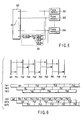
- FIG. 1 is a block diagram of a video encoding apparatus according to the present embodiment.
- FIG. 2 is a flow chart indicating steps of a process executed by the motion compensated prediction interframe encoding.
- the video encoding apparatus shown in FIG. 1 may be realized by hardware, and may be executed by software by means of a computer. A part of the process is executed by the hardware and the remaining part thereof may be executed by the software.
- the present embodiment is based on a video encoding which is a combination of a motion compensated prediction, an orthogonal transformation and a variable-length coding, the video encoding being represented by a conventional MPEG scheme.
- a video encoding method based on prediction groups including two hierarchical layers There will now be described a video encoding method based on prediction groups including two hierarchical layers.
- a video signal 100 (video frame) is input to a video encoding apparatus every frame.
- the video frame of the video signal 100 is assigned to either of prediction groups of two hierarchical layers by a motion compensation prediction unit 111 (step S11).
- the video frame is encoded by a motion compensated prediction interframe encoding, using at least one reference frame belonging to a prediction group of at least one hierarchical layer lower than the hierarchical layer of the prediction group to which the video frame is assigned (step S12).
- the reference frame stored in the frame memory set 118 is used.
- the assignment of the video frame to the prediction group of each hierarchical layer is changed between frames with time. For example, the even numbered frame is assigned to the prediction group of the first hierarchical layer, and the odd numbered frame to the prediction group of the second hierarchical layer.
- the reference frame belonging to the prediction group of each hierarchical layer is determined according to the prediction group belonging to the video frame corresponding to the encoded frame used as a reference frame. In other words, if a video frame is assigned to a prediction group of a hierarchical layer, the encoded frame obtained by encoding and local-decoding the video frame belongs to the prediction group of the same hierarchical layer.
- the process of steps S11 and 312 is explained in detail.
- a plurality of encoded frames belong to the prediction groups of the first and second hierarchical layers as reference frames.
- Two reference memory sets 118 and 119 are prepared for temporarily storing the encoded frames as the reference frames.
- the encoded frames belonging to the prediction group of the first hierarchical layer i.e., the lowest hierarchical layer
- the encoded frames belonging to the prediction group of the second hierarchical layer are temporarily stored as the reference frames in the second reference memory set 119.
- the video frame assigned to the prediction group of the first hierarchical layer is subjected to the motion compensated prediction interframe encoding, using the reference frame belonging to the prediction group of the first hierarchical layer and stored in the first reference memory set 118.
- the video frame assigned to the prediction group of the second hierarchical layer is subjected to the motion compensated prediction interframe encoding, using the reference frames belonging to both prediction groups of the first and the second hierarchical layers and stored in the first and second reference memory sets 118 and 119.
- the motion compensated prediction frame encoding will be concretely explained.
- the video frame corresponding to the video signal 100 belongs to the prediction group of the first hierarchical layer, one or more reference frames temporarily stored in the first reference memory set 118 are read out therefrom and input to the motion compensation prediction unit 111.
- the switch 120 is OFF, so that the reference frame from the first reference memory set 119 is not input to the motion compensation prediction unit 111.
- the motion compensation prediction unit 111 executes the motion compensated prediction using one or more reference frames read out from the reference memory set 118 to generate a prediction picture signal 104.
- the prediction picture signal 104 is input to the subtracter 110 to generate a predictive error signal 101 that is an error signal of the prediction picture signal 104 with respect to the input video signal 100.
- the switch 120 When the video frame corresponding to the input video signal 100 belongs to the prediction group of the second hierarchical layer, the switch 120 is ON. In this time, one or more reference frames temporarily stored in the first and second reference memory sets 118 and 119 are read out therefrom, and input to the motion compensation prediction unit 111.
- the motion compensation prediction unit 111 generates the prediction picture signal 104 and supplies to the subtracter 110 similarly to the above.
- the subtracter 110 generates the predictive error signal 101.
- the predictive error signal 101 is subjected to a discrete cosine transformation with the DCT transformer 112.
- the DCT coefficient from the DCT transformer 112 is quantized with the quantizer 113.
- the quantized DCT coefficient data 102 is divided in two routes, and encoded by the variable-length encoder 114 in one route.
- the DCT coefficient data 102 is reproduced as a predictive error signal by the dequantizer 115 and inverse DCT transformer 116 in the other route. This reproduced predictive error signal is added to the prediction picture signal 104 to generate a local decoded picture signal 103.
- the encoded frame corresponding to the local decoded picture signal 103 is temporarily stored in either of the first and second reference memory sets 118 and 119 according to the prediction group of the hierarchical layer to which the video frame corresponding to the input video signal 100 is assigned (step S13).
- the encoded frame is temporarily stored in the first reference memory set 118.
- the encoded frame is temporarily stored in the second reference memory set 119.
- the motion compensation prediction unit 111 From the motion compensation prediction unit 111 is output so-called side information 105 including a motion vector used for a motion compensated prediction, an index (first identification information) for identifying the prediction group to which the video frame belongs and an index (second identification information) which specifies the reference frame used for the motion compensated prediction interframe encoding.
- the side information is encoded by the variable-length encoding unit 114 (step S14).
- the index for identifying the prediction group is encoded as a picture type representing, for example, a prediction configuration.
- the index specifying the reference frame is encoded every macroblock.
- variable-length coded data 106 are output as variable-length coded data 106 along with the quantized DCT coefficient data which is a result of the motion compensated prediction interframe encoding (step S15).
- the side information is encoded as header information to encoded data 106.
- information indicating the maximum number of frames is encoded as header information to the encoded data 106.
- the second reference frame number setting method is a method of setting the maximum number of reference frames assigned to the prediction group of each hierarchical layer by predefining the total number of reference frames belonging to the prediction group of each hierarchical layer.
- the encoded data 106 is sent to a storage medium or a transmission medium (not shown).
- the new decoded frames are sequentially written in the reference memory sets 118 and 119 as reference frames.
- So-called FIFO (First-In First-Out) type control that the stored frames are sequentially deleted from the oldest reference frame is performed in units of a frame.
- FIFO First-In First-Out
- a random access is done to an arbitrary reference frame in each of the reference memory sets 118 and 119.
- the number of reference frames temporarily stored in the reference memory sets 118 and 119 respectively, in other words, the number of reference memories included in each of the reference memory sets 118 and 119 is determined by either of the following two methods.
- the maximum number of reference frames belonging to the prediction group of each hierarchical layer is previously established according to an encoding method or an encoding specification such as a profile and a level.
- an encoding method or an encoding specification such as a profile and a level.
- the maximum number of the reference frames determined as described above is assured every prediction group, and encoding and decoding are done. In this case, the necessary number of reference frames can be assured automatically, by making the encoding specification coincide between the video encoding apparatus and the video decoding apparatus.
- the total number of reference frames belonging to the prediction group of each hierarchical layer is predefined according to an encoding method or an encoding specification such as a profile and a level, and information on how many reference frames are assigned to the prediction group of each hierarchical layer, that is, information indicating the maximum number of frames is encoded as header information to the encoded data 106.
- the maximum number of reference frames which are most suitable for the prediction group of each hierarchical layer is dynamically assigned to the prediction group in the encoding side.
- the encoding is performed in units of frames.
- the encoding is performed in units of blocks (macroblocks).
- the video block is assigned to one of a plurality of prediction groups including at least first and second prediction groups.
- the video block is encoded according to a motion compensated prediction encoding mode, using the reference blocks depending on the one of the prediction groups to which the video block is assigned, one of the reference blocks being a decoded block.
- the first prediction group is obtained by a prediction using the reference blocks belonging to the first prediction group.
- the second prediction group is obtained by a prediction using the reference blocks belonging to at least one of the second prediction group and the first prediction group.
- the video block is encoded by each of an intraframe encoding mode, a forward prediction interframe encoding mode and a bi-directional prediction interframe encoding mode.
- the first video blocks encoded by the intraframe encoding mode and the forward prediction interframe encoding mode and the reference blocks corresponding to the first video blocks are assigned to the first prediction group.
- the second video blocks encoded by the bi-directional prediction interframe encoding mode and the reference blocks corresponding to the second video blocks are assigned to at least one of the first and second prediction groups.
- FIG. 3 is a block diagram of a video decoding apparatus corresponding to the video encoding apparatus shown in FIG. 1.
- FIG. 4 is a flow chart indicating steps of a process concerning the decoding corresponding to the motion compensated prediction interframe encoding.
- the video decoding apparatus shown in FIG. 3 may be realized by hardware, and may carry out by software. Alternately, a part of the process is executed by the hardware and the remaining part may be executed by the software.
- the encoded data 106 output from the video encoding apparatus shown in FIG. 1 is input to the video decoding apparatus shown in FIG. 3 through the storage medium or transmission medium.
- the input encoded data 200 is subjected to a variable-length decoding by a variable-length decoder 214, so that quantized DCT coefficient data 201 and side information 202 are output.
- the quantized DCT coefficient data 201 is decoded via the dequantizer 215 and inverse DCT transformer 216 so that a predictive error signal is reproduced.
- side information 202 including a motion vector encoded every macroblock, an index (first identification information) identifying the prediction group belonging to each video frame and an index (second identification information) specifying a reference frame is decoded (step 21).
- the selection of reference frame and motion compensation is performed according to the side information similarly to the encoding to generate a prediction picture signal 203.
- the reference frame is selected according to the first identification information and the second identification information (step S22).
- the result of the motion compensated prediction interframe encoding is decoded by the selected reference frame (step S23).
- the prediction picture signal 203 and the predictive error signal from the inverse DCT transformer 216 are added to generate a decoded picture signal 204.
- the decoded frame corresponding to the decoded picture signal 204 is temporarily stored in either of the first and second reference memory sets 218 and 219 according to the prediction group to which the encoded frame corresponding to the decoded frame belongs (step S24).
- the decoded frame is used as the reference frame.
- These reference memory sets 218 and 219 are controlled in FIFO type similarly to the video encoding apparatus.
- the number of reference frames belonging to the prediction group of each hierarchical layer is set according to the first and second reference frame number setting methods described in the video encoding apparatus.
- the maximum number of reference frames belonging to the prediction group of each hierarchical layer is predefined according to the first reference frame number setting method and the encoding specification
- the number of reference frames belonging to the prediction group of each hierarchical layer is set to a fixed value every encoding specification.
- the maximum number of reference frames is assigned to the prediction group of each hierarchical layer. Only the total number of reference frames is fixed, and the number of reference frames belonging to the prediction group of each hierarchical layer is dynamically controlled based on information indicating the maximum number of reference frames decoded according to the header information of encoded data.
- FIG. 5 shows a configuration of the motion compensation prediction unit 111 in the video encoding apparatus shown in FIG. 1 or the motion compensation prediction unit 211 in the video decoding apparatus shown in FIG. 3.
- available reference frames differ according to the prediction group of the hierarchical layer to which the frame to be encoded or the frame to be decoded belongs. Assuming that frame memories 302 to 304 in FIG. 5 store reference frames available as a reference frame for the encoded frame belonging to the prediction group of one hierarchical layer.
- the motion compensation prediction unit selects one from among the available reference frames every macroblock or calculates a linear sum of the available reference frames by the linear predictor 301 to predict a reference frame based on the linear sum, whereby a motion compensation is performed to generate a prediction macroblock.
- the video encoding apparatus selects the reference frame and the motion vector every macroblock so that the prediction macroblock with a small prediction error and a highest encoding efficiency is selected.
- the information of the selected reference frame and the information of the motion vector are encoded every macroblock.
- the motion compensation unit In the video decoding apparatus, the motion compensation unit generates and decodes a prediction macroblock according to the received motion vector and information of the reference frame. When the prediction is performed based on the linear sum, information concerning the linear prediction coefficient is encoded as header information of the encoded data to make the linear predictor coefficient coincide between encoding and decoding.
- FIGS. 6 to 11 show diagrams for explaining an interframe prediction configuration and a reference memory control in the present embodiment.
- FIG. 1 shows an example configured by I and P pictures and switching each frame alternatively between a prediction group a and a prediction group b. Assuming that the prediction group b is a higher hierarchical layer than the prediction group a. Also, it is assumed that the reference memory of each of the prediction group a and the prediction group b is one frame.
- a picture with a suffix a such as Ia0, Pa2 or Pa4 belongs to the prediction group a, and a picture with a suffix b such as Pb1, Pb3 or Pb5 belongs to the prediction group b.
- the attributes of these prediction groups are encoded as an extension of a picture type or an independent index and are used as header information of the video frame.
- the video frame belonging to the prediction group a can use only the frame belonging to the prediction frame a and already decoded as a reference frame.
- a prediction picture is generated using one frame belonging to either of the prediction group a and the prediction group b and already decoded or a linear sum of both decoded frames.
- the prediction group of each hierarchical layer has a reference memory corresponding to one frame.
- the number of reference frame for the video frame of the prediction group a is 1 in maximum.
- Two reference frames in maximum can be used for the video frame of the prediction group b.
- the frame Pa2 belonging to, for example, the prediction group a uses only the decoded frame Ia0 as the reference frame.
- the frame Pb3 belonging to the prediction group b uses two frames, i.e., the decoded frame Pa2 belonging to the prediction group a and the decoded frame Pb1 belonging to the prediction group b as the reference frame.
- FM1, FM2 and FM3 show physical reference memories.
- DEC, REFa and REFb show logical reference memories respectively.
- DEC, REFa and REFb are the frame memories expressed by virtual addresses.
- FM1, FM2 and FM3 are the frame memories expressed by physical addresses.
- DEC is a frame memory for temporarily storing a currently decoded frame.
- REFa and REFb show reference memories of the prediction groups a and b, respectively. Therefore, the decoded frames belonging to the prediction group a are sequentially and temporarily stored in the reference memory REFa.
- the decoded frames belonging to the prediction group b are sequentially and temporalily stored in the reference memory REBb.
- a smooth fast-forward playback can be performed by playing back the decoded frame belonging to the prediction group a at a frame rate of 2 times, for example.
- the bandwidth of a transmission channel fluctuates along with time in a video streaming, all encoded data are transmitted in normal cases.
- the encoded data belonging to the prediction group b is discarded and only the encoded data belonging to the prediction group a of the lower hierarchical layer is sent. In this case, the decoded frame can be reproduced without failure on the receiving side.
- FIG. 7 shows a modification of FIG. 6, and illustrates a prediction configuration that two frames belonging to the prediction group b are inserted between the frames belonging to the prediction group a.
- the reference memory of the prediction group of each hierarchical layer is one frame.
- decoding is possible by using a frame memory for three frames similarly to FIG. 6.
- FIG. 7 by decoding only frames of, for example, the prediction group a and playing back the encoded frames at an original frame rate, it is possible to perform a smooth three-times fast-forward playback.
- FIG. 8 shows a prediction configuration which is configured by I and P pictures and whose prediction group includes three hierarchical layers a, b and c.
- the frames of the prediction group a are assigned every four input frames.
- One frame of the prediction group b and two frames of the prediction group c are inserted between the frames of the prediction group a.
- the reference frame of the prediction groups a, b and c of respective hierarchical layers is one frame.
- the hierarchy increase in an order of a, b and c.
- the frame belonging to the prediction group a can use only one frame of the decoded prediction group a as a reference frame.
- the frame belonging to the prediction group b can use two frames of the decoded prediction groups a and b as reference frames.
- the frame belonging to the prediction group c can use three frames of the decoded prediction groups a, b and c as reference frames.
- DEC, REFa, REFb and REFc show a frame memory for temporarily storing a decoded frame, and logical frame memories for storing the reference frames of the prediction group a, the reference frames of the prediction group b and the reference frames of the prediction group c, respectively.
- FM1, FM2, FM3 and FM4 show physical frame memories for the above four frames, respectively.
- One frame that has been decoded just before the current frame is temporarily stored in the reference memories REFa, REFb and REFc.
- the currently decoded frame is written in the decoded frame memory DEC.
- the prediction group includes three hierarchical layers. Therefore, when all encoded frames not more than the prediction group c are decoded, a normal playback is performed. When the encoded frames not more than the prediction group b are decoded, the frames 1/2 of the normal number of frames are decoded. When the encoded frames not more than the prediction group a are decoded, the frames 1/4 of the normal number of frames are decoded. In either decoding, the normally decoded picture can be generated without failure of the prediction configuration.
- the fast-forward playback at a smoothly adjustable speed can be realized by dynamically controlling the hierarchical layer to be decoded. Alternatively, a transmission bit rate is dynamically changed by dynamically controlling the hierarchica layer to be transmitted.
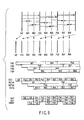
- the prediction configuration comprises I, P and B pictures, I and P pictures are assigned to the prediction group a and B picture to the prediction group b.
- the prediction group b assumes a higher hierarchical layer that that of the prediction group a.
- the prediction group a includes two frames, i.e., two reference memories, and the prediction group b includes one frame, i.e., one reference memory.
- the number of reference memories of I and P pictures of the prediction group a is 2. Therefore, it is possible to use two frames as reference frames, one of the two frames being I or P picture that is encoded or decoded just before a current P picture and the other being I or P pictures at two frames before the current P picture.
- the prediction group b has one reference frame. Therefore, one frame of B picture encoded or decoded just before the current frame is used as a reference frame. Further, it is possible to use the reference frames of three frames that are formed from B picture and I and P pictures of two past frames included in a prediction group corresponding to the lower hierarchical layer.
- FM1, FM2, FM3 and FM4 show physical frame memories
- DEC, REFa1, REFa2 and REFb show logical frame memories.
- DEC shows a frame memory for temporarily storing a frame during decoding.
- REFa1 and REFa2 show reference memories corresponding to two frames of the prediction group a.
- REFb shows a reference memory corresponding to one frame of the prediction group b.
- Idx0 and Idx1 in FIG. 9 show indexes to specify the reference frames for a frame during decoding.
- decoding for example, a frame Pa6, two frames Pa3 and Ia0 just before the frame Pa6 and belonging to the prediction group a are candidates of the reference frame.
- the indexes of the reference frames are assigned in sequence to the frames that are time-closer to the video frame.
- the index indicating the reference frame is encoded every macroblock and the reference frame is selected every macroblock.
- the prediction image is generated by I or P picture just before the picture corresponding to the macroblock.
- the macroblock of the index 1 the prediction image is generated by I or P picture at two frames before the picture corresponding to the macroblock.
- BWref in FIG. 9 shows a reference frame for the backward prediction of B picture.
- the backward reference frame for pictures Bb1 and Bb2 is a picture Pa3
- the backward reference frame for pictures Bb4 and Bb5 is a picture Pa6.
- the reference frame of the backward prediction is limited to I or P picture encoded or decoded just before due to constraint of sorting of frames. Thus, the reference frame is uniquely determined. Therefore, the reference frame BWref of the backward prediction should not be encoded as header information.
- the forward prediction of B picture can be performed by two frames selectable in maximum in the example of FIG. 9.
- the picture Pa3 that is a frame just before the picture Bb4 in time and belongs to the prediction group a and the picture Bb2 that is a frame at two frames before the picture Bb4 and belongs to the prediction group b can be used as the reference frames.
- An index indicating which reference frame is selected every macroblock or whether a prediction is performed by the linear sum of both reference frames is encoded.
- Two kinds of pictures Bb4 and Pa3 are used as the reference frames similarly to the picture Bb5.
- indexes of the reference frames numbering is added to the reference frames every video frame in a sequence to be time-closer to the reference frame for the forward prediction.
- I or P pictures stored in the reference memory are arranged in a time order and numbered.
- all reference frames stored in the reference memory, except for I or P picture that is encoded or decoded just before that it is used as the reference frame for the backward prediction are arranged in a time order and numbered.
- Idx0 and Idx1 in FIG. 9 indicate indexes generated according to the above rule.
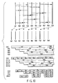
- FIG. 10 is a modification of FIG. 9, and shows a case that sets the number of reference frame to 2 and the total number of frame memories to 5 with respect to the prediction group b, that is, B picture, too.
- FM1 to FM5 show physical reference frames.
- DEC shows a buffer that temporarily stores a picture in decoding.
- REFa1 and REFa2 show the prediction group a, namely, reference memories for I and P pictures.
- REFb1 and REFb2 show the prediction group b, namely, logical reference memories for B picture respectively.
- Idx0, Idx1 and Idx2 indicate reference frame indexes allocated in the forward prediction.
- BWref shows a reference frame for the backward prediction of B picture.
- the reference frame index in the forward prediction is encoded as header information every macroblock similarly to the example of FIG. 9.
- the number of reference memories of the prediction group of each hierarchical layer is fixed. However, the number of reference frames of the prediction group of each hierarchical layer may be dynamically changed under the constant total number of reference frames.
- the number of reference memories of the prediction group b is set to 0, and at the same time the number of reference memories of the prediction group a is set to 2. Such a change may be notified with header information of encoded data from the encoding side to the decoding side.
- the selection of motion compensated prediction is controlled so that the prediction from two past frames of the prediction group a can be employed in the encoding side, and the prediction from the past frame of the prediction group b is prohibited whereas the prediction from two past frames of the prediction group a is performed.
- the decoding is performed in units of frames.
- the decoding is performed in units of blocks (macroblocks).
- the coded data includes encoded video block data, first encoded identification information indicating first and second prediction groups to which the video block data is assigned and second encoded identification information indicating reference block data used in the motion compensated prediction interframe encoding.
- the first encoded identification information and the second encoded identification information are decoded to generate first decoded identification information and second decoded identification information.
- the video block data is decoded using the reference block data belonging to the first prediction group and the reference block data belonging to at least one of the first and second prediction groups according to the first decoded identification information and the second decoded identification information.
- FIG. 11 shows a prediction configuration and how to use the frame memory when allocation of the reference memories is changed to the example of FIG. 6 as described above.
- the above way enables dynamically to set an optimum prediction configuration suitable for an input video image in the limited number of reference frames. Also, the way enables a high efficiency encoding with improved prediction efficiency.
- FIGS. 12 and 13 show a video encoding apparatus and a video decoding apparatus using prediction groups not less than three hierarchical layers, respectively.
- the reference frame set 118 or 218 belong to the lowest hierarchical layer.
- Two or more reference frame sets 119 belonging to higher hierarchical layers and two or more switches 117 and 120 are provided in the video encoding apparatus.
- Two or more reference frame sets 219 belonging to higher hierarchical layers and two or more switches 217 and 220 are provided in the video decoding apparatus.
- the switches 117 and 120 or the switches 217 and 220 are closed according to the number of hierarchical layers, the number of the reference frames is increased. In other words, the switches 117 and 120 or the switches 217 and 220 are sequentially closed according to incrementation of a hierarchy.
- a plurality of video frames assigned to a plurality of prediction groups sequentially layered from a prediction group of a lowest hierarchical layer to at least one prediction group of a higher hierarchical layer than the lowest hierarchical layer.
- the video frames are subjected to a motion compensated prediction interframe encoding, using reference frames belonging to the prediction group of the lowest hierarchical layer and the prediction group of the hierarchical layer lower than that of the prediction group to which the video frames are assigned.
- an interframe prediction configuration is made up as a layered prediction group configuration.
- An interframe prediction from the reference frame of the prediction group of a higher hierarchical layer is prohibited.
- the number of reference frames of the prediction group of each hierarchical layer is dynamically changed under the constant total number of reference frames, resulting in that the encoding efficiency is improved and the fast-forward playback can be realized with a high degree of freedom.
- the multi-hierarchical layer video image described above When the multi-hierarchical layer video image described above is played back with a home television, all hierarchical layers can be played back.
- the multi-hierarchical layer video image When the multi-hierarchical layer video image is played back with a cellular phone, the multi-hierarchical layer video image can be played back with being appropriately skipped in order to lighten a burden of a hardware. That is to say, the hierarchical layers can be selected according to the hardware of the receiver side.
Landscapes
- Engineering & Computer Science (AREA)
- Multimedia (AREA)
- Signal Processing (AREA)
- Compression Or Coding Systems Of Tv Signals (AREA)
- Compression, Expansion, Code Conversion, And Decoders (AREA)
- Television Signal Processing For Recording (AREA)
Abstract
Description
Claims (13)
- A method for encoding a video block using reference blocks, characterized by comprising:wherein the first prediction group is obtained by a prediction using the reference blocks belonging to the first prediction group, and the second prediction group is obtained by a prediction using the reference blocks belonging to at least one of the second prediction group and the first prediction group.assigning the video block to one of a plurality of prediction groups including at least first and second prediction groups; andencoding the video block according to a motion compensated prediction encoding mode, using the reference blocks depending on the one of the prediction groups to which the video block is assigned, one of the reference blocks being a decoded block,
- A video encoding method according to claim 1, characterized by encoding first identification information indicating the first prediction group and second identification information indicating the reference frame used in the motion compensated prediction interframe encoding to generate side information, and outputting the side information together with the video blocks encoded according to the motion compensated prediction interframe encoding scheme.
- A video encoding method according to claim 1 or 2, characterized in that each of the prediction groups is predicted using the corresponding number of reference blocks.
- A video encoding method according to claim 2, characterized by setting a sum of the reference blocks assigned to the prediction groups to a constant value, encoding reference block number information indicating the number of reference blocks assigned to each of the prediction groups and including the coded reference block number information in the side information.
- A video encoding method according to any one of claims 1 to 4, characterized in that assigning the video block includes encoding the video block by each of an intraframe encoding mode, a forward prediction interframe encoding mode and a bi-directional prediction interframe encoding mode, and assigning the video block includes assigning first video blocks encoded by the intraframe encoding mode and the forward prediction interframe encoding mode and the reference blocks corresponding to the first video blocks to the first prediction group, and assigning second video blocks encoded by the bi-directional prediction interframe encoding mode and the reference blocks corresponding to the second video blocks to at least one of the first and second prediction groups.
- A video encoding apparatus which encodes a video block using reference blocks, characterized by comprising:assigning means (117, 120) for assigning the video block to one of a plurality of prediction groups, andencoding means (112 to 114) for encoding the video block according to a motion compensated prediction interframe encoding mode, using the reference blocks depending on the one of the prediction groups to which the video block is assigned, one of the reference blocks being a decoded block, the encoding unit including a predictor which generates the first prediction group using the reference blocks belonging to the first prediction group, and the second prediction group using the reference blocks belonging to at least one of the second prediction group and the first prediction group.
- The video encoding apparatus according to claim 6, characterized in that the encoding means includes an encoder (114) which encodes first identification information indicating the prediction group to which the video block is assigned and second identification information indicating the reference block used in the motion compensated prediction interframe encoding to generate side information, and outputs the side information together with an encoded video block obtained by the motion compensated prediction interframe encoding.
- The video encoding apparatus according to claim 6 or 7, characterized in that each of the prediction groups is obtained by the prediction using the corresponding number of reference blocks.
- The video encoding apparatus according to claim 7, characterized in that setting means is provided for setting a sum of the reference blocks assigned to the prediction groups to a constant value, and the encoder (114) encodes reference block number information indicating the number of reference blocks assigned to each of the prediction groups and outputs the side information including the coded reference block number information.
- A video encoding apparatus according to any one of claims 6 to 9, characterized in that the encoding means includes an encoder (111 to 114) which encodes the video block by each of an intraframe encoding mode, a forward prediction interframe encoding mode and a bi-directional prediction interframe encoding mode, and the assigning means (117, 120) assigns first video blocks encoded by the intraframe encoding mode and the forward prediction interframe encoding mode and the reference blocks corresponding to the first video blocks to the first prediction group, and assigns second video blocks encoded by the bi-directional prediction interframe encoding mode and the reference blocks corresponding to the second video blocks to at least one of the first and second prediction groups.
- A method for decoding encoded data obtained by a motion compensated prediction interframe encoding, the method characterized by comprising:receiving the coded data including encoded video block data, first encoded identification information indicating first and second prediction groups to which the video block data is assigned and second encoded identification information indicating reference block data used in the motion compensated prediction interframe encoding;decoding the first encoded identification information and the second encoded identification information to generate first decoded identification information and second decoded identification information; anddecoding the video block data using the reference block data belonging to the first prediction group and the reference block data belonging to at least one of the first and second prediction groups according to the first decoded identification information and the second decoded identification information.
- A video decoding apparatus which decodes encoded data obtained by a motion compensated prediction interframe encoding, the apparatus characterized by comprising:receiving means for receiving the coded data including encoded video block data, first encoded identification information indicating first and second prediction groups to which the video block data is assigned and second encoded identification information indicating reference block data used in the motion compensated prediction interframe encoding;first decoding means (214 to 216) for decoding the first encoded identification information and the second encoded identification information to generate first decoded identification information and second decoded identification information; andsecond decoding means (211, 214 to 216) for decoding the video block data using the reference block data belonging to the first prediction group and the reference block data belonging to at least one of the first and second prediction groups according to the first decoded identification information and the second decoded identification information.
- A carrier medium carrying computer readable instructions for controlling the computer to carry out the method of any of claims 1 to 5 or 11.
Applications Claiming Priority (2)
| Application Number | Priority Date | Filing Date | Title |
|---|---|---|---|
| JP2002097892 | 2002-03-29 | ||
| JP2002097892A JP2003299103A (en) | 2002-03-29 | 2002-03-29 | Video encoding method and apparatus and video decoding method and apparatus |
Publications (2)
| Publication Number | Publication Date |
|---|---|
| EP1349396A2 true EP1349396A2 (en) | 2003-10-01 |
| EP1349396A3 EP1349396A3 (en) | 2005-07-13 |
Family
ID=27800583
Family Applications (1)
| Application Number | Title | Priority Date | Filing Date |
|---|---|---|---|
| EP20030252004 Withdrawn EP1349396A3 (en) | 2002-03-29 | 2003-03-28 | Video encoding method and apparatus, and video decoding method and apparatus |
Country Status (5)
| Country | Link |
|---|---|
| US (3) | US7298913B2 (en) |
| EP (1) | EP1349396A3 (en) |
| JP (1) | JP2003299103A (en) |
| KR (1) | KR100557445B1 (en) |
| CN (2) | CN1450813A (en) |
Cited By (3)
| Publication number | Priority date | Publication date | Assignee | Title |
|---|---|---|---|---|
| KR100694059B1 (en) | 2004-09-30 | 2007-03-12 | 삼성전자주식회사 | Method and apparatus for inter-mode encoding and decoding based on multi-time scan method |
| US7970050B2 (en) | 2004-09-30 | 2011-06-28 | Samsung Electronics Co., Ltd. | Method and apparatus for encoding and decoding data in intra mode based on multiple scanning |
| WO2017021688A1 (en) * | 2015-07-31 | 2017-02-09 | Forbidden Technologies Plc | Compressor |
Families Citing this family (31)
| Publication number | Priority date | Publication date | Assignee | Title |
|---|---|---|---|---|
| CN1898965B (en) | 2003-12-25 | 2012-04-18 | 日本电气株式会社 | Motion picture encoding method and device |
| KR100891397B1 (en) | 2004-04-28 | 2009-04-02 | 파나소닉 주식회사 | Stream generation apparatus, stream generation method, and recording medium |
| US8467447B2 (en) | 2004-05-07 | 2013-06-18 | International Business Machines Corporation | Method and apparatus to determine prediction modes to achieve fast video encoding |
| EP2348712B1 (en) * | 2004-07-01 | 2015-01-21 | Mitsubishi Electric Corporation | Playback system comprising a randomly accessible video information recording medium |
| US20060153295A1 (en) * | 2005-01-12 | 2006-07-13 | Nokia Corporation | Method and system for inter-layer prediction mode coding in scalable video coding |
| JP2006211274A (en) * | 2005-01-27 | 2006-08-10 | Toshiba Corp | Recording medium, method for reproducing the recording medium, reproducing apparatus thereof, recording apparatus for recording video data on the recording medium, and recording method thereof |
| JP4574444B2 (en) * | 2005-05-27 | 2010-11-04 | キヤノン株式会社 | Image decoding apparatus and method, image encoding apparatus and method, computer program, and storage medium |
| US7809057B1 (en) * | 2005-09-27 | 2010-10-05 | Ambarella, Inc. | Methods for intra beating reduction in video compression |
| JP4534935B2 (en) * | 2005-10-04 | 2010-09-01 | 株式会社日立製作所 | Transcoder, recording apparatus, and transcoding method |
| KR20070038396A (en) | 2005-10-05 | 2007-04-10 | 엘지전자 주식회사 | Method of encoding and decoding video signal |
| KR100891662B1 (en) | 2005-10-05 | 2009-04-02 | 엘지전자 주식회사 | Method for decoding and encoding a video signal |
| US8233535B2 (en) * | 2005-11-18 | 2012-07-31 | Apple Inc. | Region-based processing of predicted pixels |
| EP1944978A1 (en) * | 2007-01-12 | 2008-07-16 | Koninklijke Philips Electronics N.V. | Method and system for encoding a video signal. encoded video signal, method and system for decoding a video signal |
| CN101257624B (en) * | 2007-02-27 | 2011-08-24 | 华为技术有限公司 | Decoder and method for realizing random access |
| WO2008104127A1 (en) * | 2007-02-27 | 2008-09-04 | Huawei Technologies Co., Ltd. | Method for realizing random access in compressed code stream using multi-reference images and decoder |
| JP4875008B2 (en) | 2007-03-07 | 2012-02-15 | パナソニック株式会社 | Moving picture encoding method, moving picture decoding method, moving picture encoding apparatus, and moving picture decoding apparatus |
| CN101415122B (en) * | 2007-10-15 | 2011-11-16 | 华为技术有限公司 | Forecasting encoding/decoding method and apparatus between frames |
| US20100232768A1 (en) * | 2008-03-03 | 2010-09-16 | Tsuyoshi Nakamura | Recording device, reproducing device, and method |
| US8363722B2 (en) * | 2009-03-31 | 2013-01-29 | Sony Corporation | Method and apparatus for hierarchical bi-directional intra-prediction in a video encoder |
| KR101042267B1 (en) * | 2009-05-12 | 2011-06-17 | 제주대학교 산학협력단 | Double outlet |
| KR101611437B1 (en) * | 2009-10-28 | 2016-04-26 | 삼성전자주식회사 | Method and apparatus for encoding/decoding image by referencing to a plurality of frames |
| JP5020391B2 (en) * | 2010-02-22 | 2012-09-05 | パナソニック株式会社 | Decoding device and decoding method |
| US9400695B2 (en) * | 2010-02-26 | 2016-07-26 | Microsoft Technology Licensing, Llc | Low latency rendering of objects |
| US10171813B2 (en) | 2011-02-24 | 2019-01-01 | Qualcomm Incorporated | Hierarchy of motion prediction video blocks |
| JP5746792B2 (en) * | 2011-09-23 | 2015-07-08 | ケィティ、コーポレーションKt Corporation | Merge candidate block guidance method and apparatus using such method |
| JP5698644B2 (en) * | 2011-10-18 | 2015-04-08 | 株式会社Nttドコモ | Video predictive encoding method, video predictive encoding device, video predictive encoding program, video predictive decoding method, video predictive decoding device, and video predictive decode program |
| KR20150075040A (en) * | 2013-12-24 | 2015-07-02 | 주식회사 케이티 | A method and an apparatus for encoding/decoding a multi-layer video signal |
| KR20150110294A (en) | 2014-03-24 | 2015-10-02 | 주식회사 케이티 | A method and an apparatus for encoding/decoding a multi-layer video signal |
| WO2016026526A2 (en) | 2014-08-20 | 2016-02-25 | Fraunhofer-Gesellschaft zur Förderung der angewandten Forschung e.V. | Video composition |
| WO2019135270A1 (en) * | 2018-01-04 | 2019-07-11 | 株式会社ソシオネクスト | Motion video analysis device, motion video analysis system, motion video analysis method, and program |
| CN111263166B (en) * | 2018-11-30 | 2022-10-11 | 华为技术有限公司 | Video image prediction method and device |
Family Cites Families (9)
| Publication number | Priority date | Publication date | Assignee | Title |
|---|---|---|---|---|
| JPH0795589A (en) | 1993-09-20 | 1995-04-07 | Toshiba Corp | Video coding device |
| US5767911A (en) * | 1994-12-20 | 1998-06-16 | Matsushita Electric Industrial Co., Ltd. | Object-based digital image predictive coding transfer method and apparatus, and decoding apparatus |
| EP0731614B1 (en) * | 1995-03-10 | 2002-02-06 | Kabushiki Kaisha Toshiba | Video coding/decoding apparatus |
| US5883678A (en) * | 1995-09-29 | 1999-03-16 | Kabushiki Kaisha Toshiba | Video coding and video decoding apparatus for reducing an alpha-map signal at a controlled reduction ratio |
| US6031575A (en) | 1996-03-22 | 2000-02-29 | Sony Corporation | Method and apparatus for encoding an image signal, method and apparatus for decoding an image signal, and recording medium |
| JP3263807B2 (en) * | 1996-09-09 | 2002-03-11 | ソニー株式会社 | Image encoding apparatus and image encoding method |
| US6037987A (en) * | 1997-12-31 | 2000-03-14 | Sarnoff Corporation | Apparatus and method for selecting a rate and distortion based coding mode for a coding system |
| JP2000032446A (en) | 1998-07-14 | 2000-01-28 | Brother Ind Ltd | Video data compression device and storage medium |
| GB2364842A (en) | 2000-07-11 | 2002-02-06 | Motorola Inc | Method and system for improving video quality |
-
2002
- 2002-03-29 JP JP2002097892A patent/JP2003299103A/en active Pending
-
2003
- 2003-03-26 US US10/396,437 patent/US7298913B2/en not_active Expired - Fee Related
- 2003-03-28 EP EP20030252004 patent/EP1349396A3/en not_active Withdrawn
- 2003-03-28 CN CN03128539A patent/CN1450813A/en active Pending
- 2003-03-28 KR KR20030019562A patent/KR100557445B1/en not_active Expired - Fee Related
- 2003-03-28 CN CNA2006100899535A patent/CN1893652A/en active Pending
-
2007
- 2007-02-22 US US11/677,948 patent/US20070140348A1/en not_active Abandoned
- 2007-06-19 US US11/765,123 patent/US20070237230A1/en not_active Abandoned
Cited By (4)
| Publication number | Priority date | Publication date | Assignee | Title |
|---|---|---|---|---|
| KR100694059B1 (en) | 2004-09-30 | 2007-03-12 | 삼성전자주식회사 | Method and apparatus for inter-mode encoding and decoding based on multi-time scan method |
| US7970050B2 (en) | 2004-09-30 | 2011-06-28 | Samsung Electronics Co., Ltd. | Method and apparatus for encoding and decoding data in intra mode based on multiple scanning |
| US7978919B2 (en) | 2004-09-30 | 2011-07-12 | Samsung Electronics Co., Ltd. | Method and apparatus for encoding and decoding in inter mode based on multiple scanning |
| WO2017021688A1 (en) * | 2015-07-31 | 2017-02-09 | Forbidden Technologies Plc | Compressor |
Also Published As
| Publication number | Publication date |
|---|---|
| KR100557445B1 (en) | 2006-03-07 |
| KR20030078772A (en) | 2003-10-08 |
| JP2003299103A (en) | 2003-10-17 |
| US20070140348A1 (en) | 2007-06-21 |
| CN1893652A (en) | 2007-01-10 |
| CN1450813A (en) | 2003-10-22 |
| US20040017951A1 (en) | 2004-01-29 |
| US20070237230A1 (en) | 2007-10-11 |
| US7298913B2 (en) | 2007-11-20 |
| EP1349396A3 (en) | 2005-07-13 |
Similar Documents
| Publication | Publication Date | Title |
|---|---|---|
| US7298913B2 (en) | Video encoding method and apparatus employing motion compensated prediction interframe encoding, and corresponding video decoding method and apparatus | |
| US9578323B2 (en) | Moving picture coding method, and moving picture decoding method | |
| US8711931B2 (en) | Picture information coding device and coding method | |
| AU2002343215A1 (en) | Moving picture coding method, and moving picture decoding method | |
| KR20040098631A (en) | Adaptive universal variable length codeword coding for digital video content | |
| KR100988006B1 (en) | Decoding device and method, and recording medium | |
| US8179960B2 (en) | Method and apparatus for performing video coding and decoding with use of virtual reference data | |
| JP2006311589A (en) | Moving picture decoding method and apparatus | |
| KR19990041939A (en) | Compression Information Format of Image Coding System |
Legal Events
| Date | Code | Title | Description |
|---|---|---|---|
| PUAI | Public reference made under article 153(3) epc to a published international application that has entered the european phase |
Free format text: ORIGINAL CODE: 0009012 |
|
| 17P | Request for examination filed |
Effective date: 20030407 |
|
| AK | Designated contracting states |
Kind code of ref document: A2 Designated state(s): AT BE BG CH CY CZ DE DK EE ES FI FR GB GR HU IE IT LI LU MC NL PT RO SE SI SK TR |
|
| AX | Request for extension of the european patent |
Extension state: AL LT LV MK |
|
| PUAL | Search report despatched |
Free format text: ORIGINAL CODE: 0009013 |
|
| AK | Designated contracting states |
Kind code of ref document: A3 Designated state(s): AT BE BG CH CY CZ DE DK EE ES FI FR GB GR HU IE IT LI LU MC NL PT RO SE SI SK TR |
|
| AX | Request for extension of the european patent |
Extension state: AL LT LV MK |
|
| RIC1 | Information provided on ipc code assigned before grant |
Ipc: 7H 04N 7/50 B Ipc: 7H 04N 7/46 B Ipc: 7H 04N 7/36 B Ipc: 7H 04N 7/26 A |
|
| AKX | Designation fees paid |
Designated state(s): DE FR GB |
|
| STAA | Information on the status of an ep patent application or granted ep patent |
Free format text: STATUS: THE APPLICATION IS DEEMED TO BE WITHDRAWN |
|
| 18D | Application deemed to be withdrawn |
Effective date: 20101001 |