Background of the Invention
Field of the Invention
The present invention relates to a chromatic
dispersion compensating apparatus for further
increasing the capacity, the speed, and the distance
of an optical communications system hereafter.
Description of the Related Art
With the sharply growing network use in recent
years, the demand for further increasing the capacity
of a network has been rising. Currently, a wavelength
multiplexing (WDM) optical transmission system on a
basis of a transmission rate of 10 Gb/s per channel has
been put into practical use. Hereafter, a further
increase in the capacity is expected to be required,
and an ultrahigh-speed transmission system of 40 Gb/s
or faster per channel is demanded from the viewpoints
of frequency use efficiency and cost. In an
ultrahigh-speed transmission system, wavelength
degradation caused by dispersion of a transmission line
must be compensated with high accuracy.
In an optical transmission system having a
transmission rate of 10 Gb/s or faster, a chromatic
dispersion tolerance is very small. For example, the
chromatic dispersion tolerance of a 40-Gb/s NRZ system
is equal or smaller than 100 ps/nm. In the meantime,
for a terrestrical optical transmission system, span
length are not always uniform. In the case of a system
using a 1.3-µm zero dispersion single mode fiber (SMF)
of approximately 17 ps/nm/km, a chromatic dispersion
tolerance is exceeded if the length differs only several
kms. However, in an optical fiber network possessed by
a communications carrier, most span length and chromatic
dispersion values are not accurately grasped at present.
Additionally, since a chromatic dispersion value
changes with time depending on a fiber temperature,
stress, etc., a dispersion compensation amount for each
span must be adjusted not only at the start of system
operations but also in system use while strictly
monitoring a chromatic dispersion amount. For example,
a temperature change of 100 °C occurs on a 500-km DSF
(Dispersion Shifted Fiber) transmission line, its
chromatic dispersion change amount becomes
approximately 105 ps/nm that is almost equal to a
chromatic dispersion tolerance of a 40-Gb/s NRZ signal.
(chromatic dispersion change amount) =
(temperature dependency of a zero dispersion
wavelength) × (temperature change amount of a
transmission line) × (dispersion slope of the
transmission line) × (transmission distance)
= 0.03 (nm/°C) × 100 (°C) × 0.07 (ps/nm2/km) × 500 (km)
= 105 ps/nm
Therefore automatic dispersion compensation is
essential for a system using not only an SMF
transmission line, but also a 1.55-µm zero dispersion
shifted fiber (DSF) or an NZ-DSF transmission line.
Furthermore, when a wavelength-division
multiplexed(WDM) signal is transmitted, a dispersion
slope as well as chromatic dispersion must be
considered.
Fig. 1 exemplifies the configuration of a WDM
transmission system. Fig. 2 shows a change in a chromatic
dispersion amount of a transmission line due to various
change factors.
In the configuration shown in Fig. 1, optical
signals of respective wavelengths are transmitted from
optical transmitters #1 to #n of a transmitting end
station device, and coupled by an optical multiplexer.
The multiplexed optical signal is amplified and output
by an optical post-amplifier. When the process for
amplifying the optical signal is performed by the
optical post-amplifier, dispersion compensation is
made for the optical signal by a transmission dispersion
compensator in the transmittor, whose dispersion
compensation amount is fixed or variable. The optical
signal which propagates over a fiber transmission line
is amplified so that a transmission line loss is
compensated by an optical inline amplifier, which exists
partway of the fiber transmission line. Additionally,
chromatic dispersion that the optical signal undergoes
as a result of propagating over the transmission line
is compensated by an inline dispersion compensator, when
the amplification is made by the optical inline
amplifier. The dispersion compensation amount of the
inline dispersion compensator may be fixed or variable.
Furthermore, the optical signal is propagated over the
fiber transmission line via an inline amplifier, and
input to an optical receiver.
In the optical receiver, the propagated optical
signal is amplified so that its attenuation is
compensated. At this time, dispersion compensation also
at the receiver side is made by a reception dispersion
compensator in the receiver. Then, the propagated
optical signal is split into respective wavelengths by
an optical demultiplexer. For example, variable
dispersion compensators remove residual dispersion
from the optical signals of the demultiplexed
wavelengths, and the signals are received by optical
receivers #1 to #n. Here, the reason why the variable
dispersion compensators are enclosed by brackets is that
they are not always necessary. Whether or not the
variable dispersion compensator are included can be
determined by a designer depending on the details of
a design. If a constituent element is enclosed by
brackets also in the subsequent configuration drawings,
it means that the constituent element is not always
required to be included at the discretion of a designer.
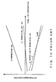
For a temperature change in the chromatic
dispersion of an optical signal, a chromatic dispersion
characteristic (a) shifts to (c) according to a
temperature change (approximately 0.03 nm/°C) in a zero
dispersion wavelength as shown in Fig. 2. In this case,
a dispersion slope does not change. Additionally, if
a transmission distance is different, the chromatic
dispersion characteristic (a) changes to (b) . In this
case, also the dispersion slope changes with the
dispersion amount. For an actual transmission line fiber
(and a dispersion compensation fiber (DCF)), the
chromatic dispersion value ((a)→(c)), and the
dispersion slope ((a)→(d)) have variations due to a
problem of a fiber manufacturing ability, even if the
length of a transmission line is the same.
As a means for compensating for chromatic
dispersion and a dispersion slope, the following methods
are considered.
The most important point in the methods (a) to (d)
is the practicability of a variable dispersion
compensator.
Fig. 3 shows a VIPA (Virtually Imaged Phased
Array) as an example of a variable dispersion
compensator. As documents about a VIPA, please see M.
Sirasaki et al., "Variable Dispersion Compensator Using
the Virtually Imaged Phased Array (VIPA) for 40-Gbit/s
WDM Transmission System", ECOC 2000, Post-deadline
paper 2.3., etc.
In a dispersion compensator using a VIPA, a
dispersion compensation amount can be successively
changed in a range from -800 ps/nm to +800 ps/nm by moving
a three-dimensional mirror in the direction of an x axis.
Fig. 4 shows a transmittance characteristic and
a group delay characteristic of a VIPA variable
dispersion compensator.
The transmittance characteristic shown in an
upper portion of this figure exhibits a periodical
wavelength dependence of transmittance in a VIPA.
Accordingly, a design must be made so that optical
signals of respective wavelengths of wavelength
multiplexed light (WDM light) pass through a high
portion of the transmittance, namely, a transmittance
window. Additionally, the figure of the group delay
represents that the group delay is periodically given
to an optical signal. It is proved from this figure that
the slope of the group delay in a portion where the
transmittance window is opened is decreasing on the
right, and negative dispersion is given to an optical
signal that passes through the window.
For example, a VIPA is designed to have a cyclic
structure where a transmission characteristic has a
frequency interval (free spectral range: FSR) of 200 GHz
(wavelength interval is 1.6 nm), and advantageous to
simultaneously compensate for a WDM signal. However,
the VIPA cannot compensate for a dispersion slope. A
system implemented by combining a VIPA dispersion
compensator and a dispersion compensation fiber in order
to collectively compensate for the dispersion
compensation and the dispersion slope is proposed by
Japanese Patent Application No. 2000-238349.
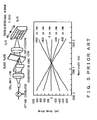
Fig. 5 shows the group delay characteristic of a
VIPA variable dispersion compensator in a channel
passband.
In a variable dispersion compensator using a VIPA
shown in an upper portion of Fig. 5, changes in the slope
of a group delay shown in a lower portion of Fig. 5 are
obtained by moving a three-dimensional mirror in the
direction of an x axis. Dispersion is obtained by
differentiation of wavelengths of a group delay.
Therefore, simultaneous dispersion compensation can be
varied and made depending on need for all of channel
bands by moving the three-dimensional mirror.
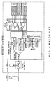
Fig. 6 exemplifies the configuration of an optical
receiver according to a conventional technique.
In the configuration example shown in this figure,
a DCF whose dispersion slope amount (a dispersion slope
of a transmission line) arranged to compensate for a
dispersion slope of the transmission line. Furthermore,
chromatic dispersion caused by the transmission line
and the DCF is collectively compensated by using a VIPA
variable dispersion compensator. As shown in Fig. 4,
the VIPA has the periodical structure of 200 GHz
intervals in order to secure a transmission band. In
a current dense WDM transmission system, 100 GHz channel
spacing(wavelength interval of 0.8 nm) is demand.
Accordingly, in Fig. 6, a received signal of 100-GHz
spacings is separated into even- and odd-numbered
channels of 200-GHz intervals by using an interleaver,
and dispersion compensation is simultaneously made by
arranging VIPA dispersion compensators respectively
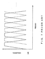
for the even- and odd-numbered channels. As shown in
Fig. 7, a transmittance window of the interlever is
opened in predetermined cycles (200 GHz in this case).
A solid line shown in this figure is a window for
extracting odd-numbered channels, whereas a dotted line
shown in this figure is a window for extracting
even-numbered channels. As described above, the
interleaver alternately samples a wavelength
multiplexed optical signal, and separates the optical
signal into even- and odd-numbered channels, so that
the channel intervals of the optical signal after being
separated are widened.
However, this configuration has a problem
stemming from the wavelength dependency of a dispersion
slope of a transmission line and a DCF, leading to a
difficulty in simultaneous dispersion compensation.
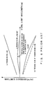
Fig. 8 shows a typical example of a dispersion
characteristic on a fiber transmission line.
Mainly on a DCF, a dispersion curve derived from
the wavelength dependency of a dispersion slope occurs
due to a manufacturing problem (however, an almost
linear dispersion characteristic is possessed in a
transmission fiber). Accordingly, residual dispersion
derived from the wavelength dependency of a dispersion
slope occurs on a transmission line and a DCF. In a
long-haul transmission, this residual dispersion
becomes a value that exceeds the dispersion tolerance
of a 40-Gb/s signal. Therefore, simultaneous
compensation is difficult with the configuration of Fig.
6 itself.
Also an implementation of a dispersion monitor for
detecting a chromatic dispersion amount (and a slope
amount), which a transmission line undergoes, is
important to realize an automatic dispersion
compensating system.
As an example of a dispersion monitor method,
there is a method using the intensity of a particular
frequency component within a received baseband signal.
Fig. 9 shows a result of detecting the intensity
of a 40-GHz component within a received baseband signal
of a 40-Gb/s NRZ signal.
Source: Y. Akiyama et al., "Automatic Dispersion
Equalization in 40 Gbit/s Transmission by
Seamless-switching between Multiple Signal
Wavelengths", ECOC '99, pp. 1-150-151
As is known from a calculation result shown on the
left side, the intensity of a 40-GHz component varies
with a chromatic dispersion amount, and becomes zero
when the dispersion amount is zero. In an experimental
result of a 100-km DSF transmission on the right side,
the dispersion amount of a transmission line varies with
a wavelength. Therefore, the intensity characteristic
of a 40-GHz component is obtained in a similar manner
as in the calculation result. A zero dispersion
wavelength of the transmission line varies with a change
in the temperature of the transmission line by
approximately 0.03 nm/°C. However, it can be verified
that also the minimum point of an intensity monitor of
the 40-GHz component varies with that change. It is known
that the intensity of a B Hz component is available as
a chromatic dispersion monitor for a B b/s modulation
signal also with other modulation methods. It is known,
for example, when chromatic dispersion is zero, the
intensity of a B Hz component becomes a maximum for an
RZ signal, and becomes a minimum for an OTDM signal
(Japanese Patent Application No. Hei 9-224056).
As another means, a method monitoring a bit error
rate characteristic or a Q value, which is detected by
each optical receiver, is considered.
To implement a low-cost dispersion monitor in a
wavelength multiplexing system, a method arranging a
dispersion monitor is important. For example, in the
case of (a) or (b) shown in Fig. 2, if chromatic
dispersion amounts of at least two signals such as
signals of wavelengths at both ends of a signal
wavelength band can be detected, a dispersion slope can
be learned by extrapolation, and a chromatic dispersion
amount of a different signal wavelength can be detected.
Additionally, in the case of (c), the dispersion
slope amount of the transmission line does not vary with
a temperature change. Therefore, if a chromatic
dispersion amount of at least one signal such as a
central wavelength signal, etc. of a signal wavelength
band can be detected, a chromatic dispersion amount of
a different signal wavelength can be detected from the
chromatic dispersion amount and the known dispersion
slope amount.
Also in the case of (d), a chromatic dispersion
amount of a different signal wavelength can be detected
by extrapolation, if a chromatic dispersion value of
at least one wavelength signal can be detected when a
dispersion slope amount (or the length of a transmission
line) is known, or if chromatic dispersion values of
at least two wavelength signals can be detected when
the dispersion slope amount is unknown.
The above described problems of conventional
techniques are summarized below.
In an optical transmission system having a
transmission rate of 10 Gb/s or faster, a chromatic
dispersion tolerance is very small. For example, the
chromatic dispersion tolerance of a 40-Gb/s NRZ system
is equal to approximately 100 ps/nm or smaller. In the
meantime, for the chromatic dispersion of a transmission
line, the following change factors exist. If a
wavelength-division multiplexed(WDM) signal is
transmitted, not only chromatic dispersion but also a
dispersion slope must be considered.
As shown in Fig. 8, a dispersion curve derived from
the wavelength dependency of a dispersion slope occurs
due to a problem of design principle also on a
transmission line, mainly on a DCF (the transmission
fiber has an almost linear dispersion characteristic) .
Accordingly, residual dispersion derived from the
wavelength dependency of the dispersion slope occurs
on the transmission line and the DCF. In a long-haul
transmission, this residual dispersion becomes a large
value that exceeds the dispersion tolerance of a 40-Gb/s
signal. This becomes a serious problem when dispersion
compensation is made collectively for all of channels.
Measures according to a known technique is as
follows. A variable dispersion compensator must be
applied to cope with time-varying chromatic dispersion
fluctuations in (4). As an example of the variable
dispersion compensator, the VIPA shown in Fig. 3 exists.
As a method arranging a variable dispersion compensator,
there are a method making compensation simultaneously
for all of channels by also comprising a slope
compensation function, a method making compensation
simultaneously for all of channels by combining with
a variable or fixed dispersion slope compensator, or
a method arranging a variable dispersion compensator
for each channel (see Japanese Patent Application No.
2000-238349) is considered.
Summary of the Invention
An object of the present invention is to provide
a chromatic dispersion compensating apparatus that can
minimize residual dispersion as much as possible at
possibly lowest cost, and its arrangement
configuration.
A first chromatic dispersion compensating
apparatus according to the present invention, in a
wavelength multiplexed optical transmission system,
comprises: a band splitting unit splitting a wavelength
multiplexed optical signal into a plurality of
wavelength bands; and a fixed dispersion compensating
unit making compensation for residual dispersion for
split wavelength multiplexed optical signals.
A second chromatic dispersion compensating
apparatus according to the present invention, in a
wavelength multiplexed optical transmission system,
comprises: a band spitting unit splitting a wavelength
multiplexed optical signal into a plurality of
wavelength bands; and a variable dispersion
compensating unit making compensation simultaneously
for split wavelength multiplexed optical signals.
A third chromatic dispersion compensating
apparatus according to the present invention, in a
wavelength multiplexed optical transmission system,
comprises: a variable dispersion compensating unit
making dispersion compensation simultaneously for a
whole or part of a wavelength multiplexed optical
signal; an optical splitting unit splitting the
wavelength multiplexed optical signal; and a fixed
dispersion compensating unit making compensation for
residual dispersion of an optical signal of each split
channel.
A fourth chromatic dispersion compensating
apparatus, in a wavelength multiplexed optical
transmission system, comprises: a band splitting unit
splitting a wavelength multiplexed optical signal into
a plurality of wavelength bands; and a
dispersion compensating unit reducing a residual
dispersion difference between bands for respective
split wavelength bands.
A fifth chromatic dispersion compensating
apparatus, in a multi-span optical transmission system,
comprises a dispersion compensating unit making 105-to
120-percent over-compensation for a chromatic
dispersion amount of each span in each inline amplifier
after span.
According to the present invention, an efficient
and effective chromatic dispersion compensating
apparatus and a method thereof can be provided at low
cost.
Brief Description of the Drawings
Fig. 1 exemplifies the configuration of a
wavelength multiplexing transmission system;
Fig. 2 shows changes in a chromatic dispersion
amount of a transmission line due to various change
factors;
Fig. 3 shows a VIPA (Virtually Imaged Phased
Array) as an example of a variable dispersion
compensator;
Fig. 4 shows a transmittance characteristic and
a group delay characteristic of a VIPA variable
dispersion compensator;
Fig. 5 shows a group delay characteristic of a VIPA
variable dispersion compensator;
Fig. 6 exemplifies the configuration of an optical
receiver of a conventional technique;
Fig. 7 explains the operations of an interleaver;
Fig. 8 shows a typical example of a dispersion
characteristic on a fiber transmission line;
Fig. 9 shows a result of detecting the intensity
of a 40-GHz component within a receiving baseband signal
of a 40-Gb/s NRZ signal;
Fig. 10 shows fluctuations of chromatic
dispersion on a transmission line due to dispersion
slope variations;
Fig. 11 explains the principle of preferred
embodiments according to the present invention;
Fig. 12 exemplifies a first configuration
implementing a preferred embodiment according to the
present invention;
Fig. 13 exemplifies a second configuration of the
preferred embodiment according to the present
invention;
Fig. 14 exemplifies a third configuration of the
preferred embodiment according to the present
invention;
Fig. 15 exemplifies a fourth configuration of the
preferred embodiment according to the present
invention;
Fig. 16 exemplifies a fifth configuration of the
preferred embodiment according to the present
invention;
Fig. 17 exemplifies a sixth configuration of the
preferred embodiment according to the present
invention;
Fig. 18 explains a chromatic dispersion
compensation method according to another preferred
embodiment of the present invention;
Fig. 19 exemplifies a seventh configuration
according to another preferred embodiment of the present
invention;
Fig. 20 exemplifies an eighth configuration of the
preferred embodiment according to the present
invention;
Fig. 21 exemplifies a ninth configuration of the
preferred embodiment according to the present
invention;
Fig. 22 exemplifies a tenth configuration of the
preferred embodiment according to the present
invention;
Fig. 23 exemplifies an eleventh configuration of
the preferred embodiment according to the present
invention;
Fig. 24 exemplifies a twelfth configuration of the
preferred embodiment according to the present
invention;
Figs. 25A and 25B show the principle
configurations in the case where a preferred embodiment
according to the present invention is applied to an
inline amplifier;
Fig. 26 explains the principle of a dispersion
compensation method according to a preferred embodiment
of the present invention (No. 1);
Fig. 27 explains the principle of a dispersion
compensation method according to a preferred embodiment
of the present invention (No. 2);
Figs. 28A and 28B show the configurations in the
case where fixed dispersion compensators for respective
wavelength bands are replaced by variable dispersion
compensators in correspondence with Fig. 25;
Figs. 29A and 29B exemplify the configurations of
a specific inline amplifier in the case where wavelength
band split compensation is made (No. 1);
Figs. 30A and 30B exemplify the configurations of
a specific inline amplifier in the case where wavelength
band split compensation is made (No. 2);
Figs. 31A and 31B exemplify the configurations of
a specific inline amplifier in the case where wavelength
band split compensation is made (No. 3);
Figs. 32A and 32B exemplify the configurations of
a specific inline amplifier in the case where wavelength
band split compensation is made (No. 4);
Figs. 33A and 33B exemplify the configurations of
a specific inline amplifier in the case where wavelength
band split compensation is made (No. 5);
Fig. 34 exemplifies the configuration of a system
using the inline amplifiers that make the band split
compensation shown in Figs. 29 to 33 (No. 1);
Fig. 35 exemplifies the configuration of a system
using the inline amplifiers that make the band split
compensation shown in Figs. 29 to 33 (No. 2);
Fig. 36 exemplifies the configuration of a system
using the inline amplifiers that make the band split
compensation shown in Figs. 29 to 33 (No. 3);
Figs. 37A to 37C show a Q penalty for residual
dispersion in the case of an inline dispersion
compensation ratio DDCL=100 percent and 114 percent in
a 600-km SMF transmission;
Fig. 38 shows a Q penalty characteristic against
an inline residual dispersion amount in the case where
residual dispersion is made zero by adjusting a
dispersion compensation amount at a receiver side in
each case in a 600-km SMF transmission;
Fig. 39 exemplifies a first configuration
corresponding to a preferred embodiment for optimizing
an inline dispersion compensation amount;
Fig. 40 shows a further specific example of the
configuration shown in Fig. 39; and
Fig. 41 exemplifies the configuration implemented
by combining band split dispersion compensation and
inline over-compensation.
Description of the Preferred Embodiments
In preferred embodiments according to the present
invention, dispersion compensation is made by splitting
a wavelength band into predetermined bands, if residual
dispersion derived from the wavelength dependency of
a dispersion slope of a transmission line and a DCF is
too large to be ignored.
Fig. 11 explains the principle of preferred
embodiments according to the present invention.
For example, in the case of a residual dispersion
characteristic of (a) a transmission line and (b) a DCF1
(for simultaneous compensation for all of channels)
shown in Fig. 11, a wavelength multiplexed signal is
demultiplexed into a plurality of wavelength bands (four
bands in this figure), and a dispersion compensation
amount is finely adjusted by arranging (c) a fixed
dispersion compensator (DCF) or a variable dispersion
compensator (VDC) for each of the wavelength bands, so
that the residual dispersion of all of the channels can
be reduced to a small value (d) . In this figure,
chromatic dispersion of a predetermined amount is given
to all of the channels within the wavelength band so
that 100-percent dispersion compensation is made for
a central wavelength of each of the wavelength bands.
If fine adjustment is made with a fixed dispersion
compensator, a fixed dispersion compensation amount
must be determined by measuring the dispersion
characteristic of a transmission line beforehand (or
grasping a dispersion shift amount as a characteristic
specific to a fiber) . However, if the dispersion of the
transmission line varies with time due to a temperature
change, the chromatic dispersion amounts of all of the
channels vary in the same direction. Therefore, the
compensation state can be maintained by varying variable
dispersion compensators concurrently used.
All of the following configurations show examples
in the case where a wavelength interval of a transmitted
wavelength multiplexed signal is 100 GHz (approximately
0.8 nm). Additionally, only a configuration example of
a dispersion compensator within an optical receiver is
shown. However, a similar configuration can be made also
in the case where a dispersion compensator is arranged
within an inline amplifier or a transmitter side
station.
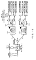
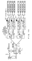
Fig. 12 exemplifies a first configuration for
implementing a preferred embodiment according to the
present invention.
In this configuration example, after dispersion
compensation is made simultaneously for all of channels
by a DCF1 and a variable dispersion compensator for
100-GHz intervals, wavelength intervals are separated
into 200-GHz (approximately 1.6 nm) intervals by an
interleaver. Then, the wavelength bands are
respectively split into n wavelength bands by band split
filters, and fine adjustment is made by a fixed
dispersion compensator in each of the wavelength bands.
Firstly, a wavelength multiplexed optical signal
propagated over a fiber transmission line 10 is
amplified by an optical pre-amplifier 11, which is a
receiver shown in Fig. 12, and at the same time, its
dispersion slope is compensated by the DCF1. Then, the
optical signal of 100-GHz intervals is input to a
variable dispersion compensator 12, which makes
dispersion compensation collectively for all of
wavelengths. Next, the optical signal of 100-GHz
intervals is separated into even- and odd-numbered
channels by an interleaver 13, so that the optical signal
is converted into optical signals of 200-GHz intervals.
The optical signals are respectively input to band split
filters 14-1 and 14-2, which split their wavelength
bands into n bands. After residual dispersions in the
respective bands are compensated by a DCF for a first
order dispersion fine adjustment 15, the signals are
demultiplexed into optical signals of the respective
channels, and received by optical receivers #1 to #40
respectively.
Here, the number of the optical receivers is 40.
This is because Fig. 12 assumes the number of multiplexed
wavelengths to be 40. However, the number of multiplexed
wavelengths is not limited to this value. Rather,
optical receivers the number of which is according to
the number of multiplexed wavelengths must be arranged.
This is similar also in the explanations of the following
configuration examples.
Here, optical signals input to the band split
filter 14-1 are signals of odd-number channels, whereas
optical signals input to the band split filter 14-2 are
signals of even-numbered channels. Band split filters
are already commercialized and sold by companies such
as JDS Uniphase, OPlink, Dicon, Avanex, HD Fiber Systems,
Chorum, etc.
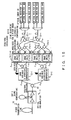
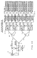
Fig. 13 exemplifies a second configuration of the
preferred embodiment according to the present
invention.
In contrast to Fig. 12, Fig.13 shows the
configuration where variable dispersion compensators
for 200-GHz intervals are arranged after wavelength
intervals are separated into 200-GHz intervals.
An optical signal propagated over a fiber
transmission line 10 is amplified by an optical
pre-amplifier 11, and at the same time, its dispersion
slope is compensated by a DCF1. The optical signal is
then input to an interleaver 13, which samples the
wavelength multiplexed optical signal of 100-GHz
intervals as optical signals of 200-GHz intervals, and
transmits odd-numbered and even-numbered channels
respectively to variable dispersion compensators for
200-GHz intervals 12-1 and 12-2. The variable dispersion
compensators 12-1 and 12-2 respectively perform a
chromatic dispersion compensation process for the input
optical signals, and input the signals to band split
filters 14-1 and 14-2. The band split filters 14-1 and
14-2 split the sampled optical signals into n bands.
Then, fine adjustment for a first order dispersion is
made by DCFs15 for the respective bands. Optical signals
of the respective bands for which the fine adjustment
is made are demultiplexed into optical signals of the
respective channels by optical DEMUXs 16, and received
by optical receivers #1 to #40.
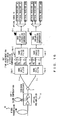
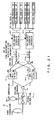
Fig. 14 exemplifies a third configuration of the
preferred embodiment according to the present
invention.
In contrast to Fig. 13, Fig. 14 shows the
configuration where wavelength intervals are separated
into 400-GHz (approximately 3.2 nm) intervals by using
two-stage interleavers, optical signals are then split
into n wavelength bands by band split filters, and fine
adjustment is made for the respective wavelength bands
by fixed dispersion compensators. The band split filters
have a guard band (wavelength range with no
transmittance) in a split wavelength position because
of its characteristic. By widening a wavelength interval
of a signal light wavelength by an interleaver, a
requirement for the band split filter is relaxed (the
number of channels that cannot be transmitted becomes
zero or is reduced even if a guard band is wide) . Also
a configuration where the number of stages of
interleavers is further increased to still more widen
a wavelength interval may be implemented.
An optical signal propagated over a fiber
transmission line 10 is amplified by an optical
pre-amplifier, and at the same time, its dispersion
slope is compensated by a DCF1. The optical signal is
then separated into even- and odd-numbered channels by
an interleaver 13. As a result, the wavelength intervals
of the optical signals change from 100 to 200 GHz. Then,
chromatic dispersions of the optical signals of 200-GHz
intervals are compensated by variable dispersion
compensators 12-1 and 12-2. Interleavers 20-1 and 20-2
further sample the optical signals of 200-GHz intervals
to optical signals of 400-GHz intervals, which are
respectively input to band split filters 14-1 to 14-4.
The band split filters 14-1 to 14-4 split the bands of
the input signals into n bands. Then, DCFs15 make fine
adjustment for a first order dispersion compensation
for the respective bands, and the signals are input to
optical DEMUXs 16. Optical signals that are
demultiplexed into respective channels by the optical
DEMUXs 16 are received by optical receivers #1 to #40
respectively. Widening a wavelength interval of an
optical signal before its band is split as described
above reduces the possibility that an optical signal
comes at a band boundary when the band is split.
Accordingly, this is effective in a sense that an optical
signal erased by band splitting is eliminated.
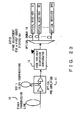
Fig. 15 exemplifies a fourth configuration of the
preferred embodiment according to the present
invention.
In contrast to Fig. 14, Fig. 15 shows the
configuration where after signals of the same wavelength
band are combined by interleavers subsequent to band
split filters, fine adjustment is made by fixed
dispersion compensators. With this configuration, the
number of fixed dispersion compensators for fine
adjustment can be reduced.
A wavelength multiplexed signal propagated over
a fiber transmission line 10 is amplified by an optical
pre-amplifier 11, and at the same time, its dispersion
slope is compensated by a DCF1. Then, the optical signal
is sampled by an interleaver 13, and optical signals
having channel intervals (200 GHz) that are double the
channel intervals (100 GHz) of the original wavelength
multiplexed optical signal are respectively input to
variable dispersion compensators 12-1 and 12-2. After
dispersion compensation is made for the optical signals
by the variable dispersion compensators 12-1 and 12-2,
the signals are further sampled by interleavers 20-1
and 20-2. The signals change to those having channel
intervals (400 GHz) that are four times the wavelength
intervals (100 GHz) of the original wavelength
multiplexed optical signal, and are input to band split
filters 14-1 to 14-4.
The band split filters 14-1 to 14-4 respectively
split the input optical signals into n bands. Then,
optical signals of identical wavelength bands are
combined by interleavers 21a-1 to 21b-n and 22-1 to 22-n
in stages, and fine adjustment for a first order
dispersion compensation is made for the respective bands
by DCFs15. After the fine adjustment is made, the optical
signals are input to optical DEMUXs 16, which
demultiplex the signals into respective channels. The
signals are then received by optical receivers #1 to
#40.
Fig. 16 exemplifies a fifth configuration
according to the preferred embodiment of the present
invention.
In this configuration example, after compensation
is made simultaneously for all of channels by a DCF1,
optical signals are split into n wavelength bands by
band split filters, fine adjustment is made for the
respective wavelength bands by fixed dispersion
compensators, and variable dispersion compensators are
arranged after the optical signals are coupled by band
couple filters.
An optical signal propagated over a fiber
transmission line 10 is amplified by an optical
pre-amplifier 11, and at the same time, its dispersion
slope is compensated by the DCF1. Then, the wavelength
multiplexed optical signal is sampled by an interleaver
13, and optical signals of 200-GHz intervals are input
to band split filters 14a-1 and 14a-2. The band split
filters 14a-1 and 14a-2 respectively split the optical
signals into n bands, and input the signals to DCFs15
for the respective bands. Then, the DCFs15 make fine
adjustment for a first order dispersion compensation.
The optical signals for which the fine adjustment is
made are input to band couple filters 14b-1 and 14b-2,
which couple the respective bands and input the coupled
signals to variable dispersion compensators 12-1 and
12-2. The variable dispersion compensators 12-1 and 12-2
compensate for chromatic dispersion. The optical
signals are demultiplexed into respective channels by
optical DEMUXs 16, and received by optical receivers
#1 to #40.
Fig. 17 exemplifies a sixth configuration
according to the preferred embodiment of the present
invention.
In contrast to Fig. 16, Fig. 17 shows the
configuration where wavelength intervals are separated
into 400-GHz (approximately 3.2 nm) intervals by using
two-stage interleavers, optical signals are split into
n wavelength bands by band split filters, fine
adjustment is made for each of the wavelength bands by
fixed dispersion compensators, and variable dispersion
compensators are arranged after the wavelength band
signals are coupled by band couple filters. Although
the number of variable dispersion compensators
increases, requirements for non-transmission
wavelength bands of the band split filters are relaxed.
An optical signal propagated over a fiber
transmission line 10 is amplified by an optical
pre-amplifier 11, and at the same time, its dispersion
slope is compensated by a DCF1. Then, the optical signal
is sampled by an interleaver 13, and separated into odd-and
even-numbered channels of 200-GHz intervals. The
respective odd- and even-numbered channels thus
separated are further separated into even- and
odd-numbered channels by interleavers 20-1 and 20-2,
and input to band split filters 14a-1 to 14a-4.
The band split filters 14a-1 to 14a-4 split the
respective optical signals into n bands, and input the
optical signals of the respective bands to DCFs for a
first order dispersion compensation fine adjustment 15,
which make fine adjustment for dispersion compensation.
Then, the optical signals for which the fine adjustment
is made are coupled by band couple filters 14b-1 to 14b-4.
Dispersion compensation is then made for the optical
signals by variable dispersion compensators 12-1 to 12-4.
Outputs of the variable dispersion compensators 12-1
to 12-4 are demultiplexed into respective channels by
optical DEMUXs 16, and received by optical receivers
#1 to #40.
Fig. 18 explains a chromatic dispersion
compensation method according to another preferred
embodiment of the present invention.
This figure shows another dispersion compensation
method in the case of a residual dispersion
characteristic of (a) a transmission line and (b) a DCF1
(for compensation collectively for all of channels),
which is similar to that shown in Fig. 11. A plurality
of (four in this figure) dispersion compensation fibers
(fixed dispersion compensators) are arranged, and fine
adjustment is made for their lengths, so that a
dispersion slope of the transmission line, the DCF1 and
the DCFs2 (a, b,...) is canceled. Furthermore, residual
chromatic dispersion is collectively compensated by
arranging variable dispersion compensators for
respective wavelength bands, thereby reducing the
residual dispersion of all of channels to a smaller value
in comparison with the case shown in Fig. 11. Because
the fine adjustment is made for the dispersion slope
with the fixed dispersion compensators in a similar
manner as in Fig. 11, the dispersion and the dispersion
slope characteristic of a transmission line must be
measured beforehand. If the dispersion of the
transmission line changes with time due to a temperature
change thereafter, the chromatic dispersion amounts of
all of the channels vary in the same direction. Therefore,
the compensation state can be maintained by making a
concurrently used variable dispersion compensator
variable.
According to the preferred embodiments of the
present invention, dispersion compensation for all of
channels can be effectively made at low cost and in less
size in a wavelength multiplexing transmission system,
even if residual dispersion derived from the wavelength
characteristic of a dispersion slope of a transmission
line and a DCF occurs, or if variations of chromatic
dispersion and a dispersion slope are large. As a result,
a long-haul transmission can be implemented.
The following configuration example is an example
of configuration that can implement not only the
principle shown in Fig. 18 but also the principle shown
in Fig. 11.
Fig. 19 exemplifies a seventh configuration
according to another preferred embodiment of the present
invention.
This figure shows the configuration where after
compensation is made collectively for all of channels
by a DCF1, wavelength intervals are separated into
200-GHz (approximately 1.6 nm) intervals, the optical
signals are split into n wavelength bands by band split
filters, and fine adjustment is made for the respective
wavelength bands by variable dispersion compensators.
Variable dispersion compensators the number of which
is double the number of wavelength bands are required.
A fixed dispersion compensator for making fine
adjustment for dispersion slope compensation may be
arranged to make compensation for chromatic dispersion
and a dispersion slope, which is explained with
reference to Fig. 18, with high accuracy.
A wavelength multiplexed optical signal
propagated over a fiber transmission line 10 is
amplified by an optical pre-amplifier 11, and at the
same time, its dispersion slope is compensated by a DCF1.
Then, the optical signal is separated into odd- and
even-numbered channels by an interleaver 13, and the
separated optical signals are respectively input to band
split filters 14-1 and 14-2. The band split filters 14-1
and 14-2 split the wavelength bands into n bands, and
output optical signals. DCFs30 are used to make fine
adjustment for dispersion slope compensation. However,
they may not be arranged if dispersion compensation with
high accuracy is not demanded on a receiving side. The
reason why the DCFs30 are enclosed by brackets is that
it is desirable to arrange the DCFs30, but it does not
matter unless they are arranged.
After the optical signals pass through the DCFs30,
dispersion compensation is made for their respective
bands by variable dispersion compensators 12a-1 to 12a-n,
and 12b-1 to 12b-n. The optical signals are then
transmitted to optical DEMUXs 16, which demultiplex the
optical signals into respective channels. Optical
signals of the respective channels are received by
optical receivers #1 to #40.
Fig. 20 exemplifies an eighth configuration of the
preferred embodiment according to the present
invention.
In contrast to Fig. 19, Fig. 20 shows the
configuration where wavelength intervals are separated
into 400-GHz (approximately 3.2 nm) intervals by using
two-stage interleavers, the optical signals are then
split into n wavelength bands by band split filters,
and fine adjustment is made for the respective
wavelength bands by variable dispersion compensators.
Variable dispersion compensators the number of which
is four times the number of wavelength bands are required.
A fixed dispersion compensator for making fine
adjustment for dispersion slope compensation may be
arranged to make the compensation for chromatic
dispersion and a dispersion slope, which is explained
with reference to Fig. 18, with high accuracy.
An optical signal propagated over a fiber
transmission line 10 is amplified by an optical
pre-amplifier 11, and at the same time, its dispersion
slope is compensated by a DCF1. Then, the optical signal
is separated into odd- and even-numbered channels by
an interleaver 13. The optical signals are further
sampled and separated by interleavers 20-1 and 20-2 in
a succeeding stage, and input to band split filters 14-1
to 14-4. The band split filters 14-1 to 14-4 split the
respective input optical signals into n bands. Fine
adjustment is made for dispersion slope compensation
for the split signals by arbitrarily arranged DCFs30,
and dispersion compensation is made for the signals by
variable dispersion compensators 12a-1 to 12d-n. Then,
the optical signals are input to optical DEMUXs 16, which
demultiplex the signals into respective channels. The
optical signals are then received by optical receivers
#1 to #40.
Fig. 21 exemplifies a ninth configuration of the
preferred embodiment according to the present
invention.
In contrast to Fig. 20, Fig. 21 shows the
configuration where fine adjustment is made by variable
dispersion compensators after signals of the same
wavelength band are combined by an interleaver. With
this configuration, the number of variable dispersion
compensators can be reduced. The number of variable
dispersion compensators becomes equal to the number of
wavelength bands in this example.
An optical signal propagated over a fiber
transmission line 10 is amplified by an optical
pre-amplifier 11, and at the same time, its dispersion
slope is compensated by a DCF1. Then, the optical signal
is separated into odd- and even-numbered channels by
an interleaver 13, and the optical signals are
respectively input to band split filters 14-1 and 14-2.
The band split filters 14-1 and 14-2 split the bands
of the optical signals into n bands, and optical signals
of the same band among the bands split by the band split
filters 14-1 and 14-2 are combined by interleavers 21-1
to 21-n. Fine adjustment is made for dispersion slope
compensation for the respective bands by arbitrarily
arranged DCFs30. Then, dispersion compensation is made
by variable dispersion compensators 12-1 to 12-n, and
the optical signals are demultiplexed into respective
channels by optical DEMUXs 16, and received by optical
receivers #1 to #40.
Fig. 22 exemplifies a tenth configuration of the
preferred embodiment according to the present
invention.
In contrast to Fig. 21, Fig. 22 shows the
configuration where fine adjustment is made by variable
dispersion compensators after signals of the same
wavelength band are combined by an interleaver
subsequent to band split filters. With this
configuration, the number of variable dispersion
compensators can be reduced. In this example, 200-GHz
variable dispersion compensators the number of which
is double the number of wavelength bands are required.
Or, 100-GHz variable dispersion compensators the number
of which is equal to the number of wavelength bands may
be arranged after signals of the same wavelength bands
are further combined into 100-GHz signals by
interleavers.
An optical signal propagated over a fiber
transmission line is amplified by an optical
pre-amplifier 11, and at the same time, its dispersion
slope is compensated by a DCF1. Then, the optical signal
is separated into odd- and even-numbered channels by
an interleaver 13. The signals are further sampled and
separated by interleavers 20-1 and 20-2, and
respectively input to band split filters 14-1 to 14-4.
The band split filters 14-1 to 14-4 separate the input
optical signals into n bands. Next, optical signals of
the same band are combined by interleavers 21a-1 to 21b-n,
and fine adjustment is made for dispersion slope
compensation for the respective bands by DCFs30. Then,
dispersion compensation is made for the signals by
variable dispersion compensators 12a-1 to 12b-n. The
optical signals are demultiplexed into respective
channels by optical DEMUXs 16, and received by optical
receivers #1 to #40.
Fig. 23 exemplifies an eleventh configuration of
the preferred embodiment according to the present
invention.
This figure shows the configuration where
compensation is made simultaneously for all of channels
by a DCF1 and a variable dispersion compensator for
100-GHz intervals, all of the channels are then
demultiplexed by an optical DEMUX, and fine adjustment
is made for the respective channels by fixed dispersion
compensators.
An optical signal propagated over a fiber
transmission line 10 is amplified by an optical
pre-amplifier 11, and at the same time, its dispersion
slope is compensated by a DCF1. Then, chromatic
dispersion compensation is made for the signal by a
variable dispersion compensator 12. The optical signal
for which the chromatic dispersion compensation is made
is demultiplexed into respective channels by an optical
DEMUX 16. Then, fine adjustment for a first order
dispersion is made for the respective channels by DCFs15,
and the signals are received by optical receivers #1
to #40.
Fig. 24 exemplifies a twelfth configuration of the
preferred embodiment according to the present
invention.
In contrast to Fig. 19, this figure shows the
configuration where variable dispersion compensators
for 200-GHz intervals are arranged after wavelength
intervals are separated into 200-GHz intervals.
An optical signal propagated over a fiber
transmission line 10 is amplified by an optical
pre-amplifier 11, and at the same time, its dispersion
slope is compensated by a DCF1. Then, the optical signal
is sampled and separated into odd- and even-numbered
channels by an interleaver 13. Dispersion compensation
is then made for the respective optical signals by
variable dispersion compensators 12-1 and 12-2, and the
signals are demultiplexed into respective channels by
optical DEMUXs 16. Fine adjustment for a first order
dispersion is then made for the optical signals of the
respective channels by DCFs15, and the signals are
received by optical receivers #1 to #40.
A dispersion compensating apparatus in an inline
amplifier is explained next.
As a solution to the above described (2)
incompleteness of a slope compensation rate of a DCF,
(3) manufacturing variations of a slope coefficient of
a transmission line/DCF, and (5) influence of the
wavelength dependency of a chromatic dispersion slope,
a method making compensation by splitting a wavelength
band into a plurality of bands is also used.
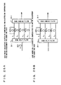
Figs. 25A and 25B show the principle
configurations in the case where a preferred embodiment
according to the present invention is applied to an
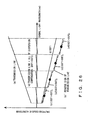
inline amplifier. Figs. 26 and 27 explain the principle
of a dispersion compensation method according to the
preferred embodiment of the present invention.
Fig. 25A shows the fundamental configuration (the
case where fixed dispersion compensators are applied)
of compensation made by splitting a wavelength band into
four bands. After a dispersion compensator DCF1
(dispersion compensation amount d1) is arranged in
common to all of channels of a wavelength multiplexed
signal, the signal is split into four wavelength bands
(Λ1, Λ2, Λ3, and Λ4 from a short wavelength side) by a
band split filter 20-1. DCF21, DCF22, DCF23, and DCF24,
which are intended to compensate for residual dispersion
differences among the bands, are arranged in the
respective bands. In each span or a plurality of spans,
adjustment is made so that 100-percent dispersion
compensation is made in central wavelengths of the
respective wavelength bands by the fixed dispersion
compensators DCF21, DCF22, DCF23, and DCF24 in the case
of the residual dispersion characteristics of (a) a
transmission line and (b) a DCF1 shown in Fig. 26. As
a result, the residual dispersions of all of the channels
can be reduced to small values (d) . Not only a dispersion
compensation fiber but also various types of devices
such as a chirped fiber Bragg grating (CFBG), a VIPA
dispersion compensator, etc. are applicable as a
dispersion compensator. Fig. 25B shows the
configuration where not a dispersion compensator DCF1
for making compensation collectively for all of channels,
but only dispersion compensators for making adjustment
for bands are applied. Its effect is similar to that
in the case of Fig. 25A. However, dispersion
compensators whose dispersion compensation amounts are
large as shown in Fig. 27 must be applied as the fixed
dispersion compensators DCF21, DCF22, DCF23, and DCF24.
The bands of the optical signals for which the
dispersion compensation is made are coupled by a band
split filter 20-2 (that also functions as an element
for coupling bands because of the reversibility of light
propagation, which is a characteristic of an optical
element, although its name is band split), and the signal
of the coupled bands is output.
Fig. 28 shows the configurations where the fixed
dispersion compensators for the respective wavelength
bands are replaced by variable dispersion compensators
in correspondence with Figs. 25A and 25B.
How to set a dispersion compensation amount is the
same as those in Fig. 26 (the case of the configuration
shown in Fig. 28A) and Fig. 27 (the case of the
configuration shown in Fig. 28B). However, since the
dispersion compensation amounts are variable,
dispersion compensation with higher accuracy can be made,
and besides, a dispersion amount that changes with time
due to a temperature change in a transmission line, or
the like can be coped with.
Namely, in Fig. 28A, after dispersion
compensation is made for an input optical signal by a
chromatic dispersion compensation fiber DCF1, the
signal is split into respective bands Λ1 to Λ4 by a band
split filter 20-1, and input to a band split filter 20-2.
The band split filter 20-2 couples optical signals,
which are split into the respective bands and input,
and outputs the coupled signal as an optical signal of
one band. Fig. 28B shows the configuration where a
chromatic dispersion compensation fiber DCF1 that makes
dispersion compensation collectively is omitted from
the configuration shown in Fig. 28A.
According to the preferred embodiments of the
present invention, dispersion compensation can be
effectively made for all of channels at low cost and
in less size in a dense wavelength multiplexing
transmission system, even if manufacturing variations
of chromatic dispersion/dispersion slope of a
transmission line and a DCF are large, if slope
compensation ratio of a DCF is low, or if residual
dispersion derived from fourth order dispersion occurs.
As a result, a long-haul transmission can be
implemented.
Figs. 29A to 33B exemplify specific
configurations of an inline amplifier in the case of
wavelength band split compensation.
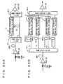
In Fig. 29A, a pump light source 25 for distributed
Raman amplification is arranged, and an EDFA 26 is
arranged in the next stage, so that an optical signal
is amplified. After dispersion compensation is
simultaneously made by a chromatic dispersion
compensation fiber DCF1, a wavelength band is split into
two bands Λ1 and Λ2 by a band split filter 20-1. Dispersion
compensation is further made for one of the bands by
a chromatic dispersion compensation fiber DCF2. For the
band Λ1, a (variable or fixed) optical attenuator 27 for
providing a loss, which is almost equal to an optical
loss produced by the chromatic dispersion compensation
fiber DCF2, is arranged depending on need. After optical
signals of the respective bands are coupled by a band
split filter 20-2, the coupled signal is output,
amplified by an EDFA 28, and output to a transmission
line.
Fig. 29B shows the configuration where a
wavelength band is split into n bands. The fundamental
configuration is the same as that shown in Fig. 29A.
Accordingly, the same constituent elements are denoted
with the same reference numerals, and an explanation
about the configuration is omitted.
Figs. 29A and 29B exemplify the configurations
where the inline amplifier is configured by the
two-stage erbium-doped fiber optical amplifiers
(EDFAs). Distributed Raman amplification (DRA) for
improving an optical signal-to-noise ratio (OSNR) is
made as occasion demands. Fig. 29A shows the
configuration where a wavelength band is split into two
bands. In this figure, a wavelength band is split into
a blue band (Λ1) on a short wavelength side and a red
band (Λ2) on a long wavelength side by using the band
split filter. The dispersion compensator (DCF1)
arranged in the stage preceding the band split filter
is set so that chromatic dispersion is optimally
compensated in a central channel of the blue band (Λ1).
Therefore, a dispersion compensator is not arranged on
an optical path of the blue band (Λ1). However, the
variable or fixed optical attenuator for providing an
optical loss that is almost equal to a dispersion
compensator DCF2 is inserted on the optical path of the
blue band depending on need. Assume that the dispersion
slope of the transmission line fiber is S (ps/nm2/km),
the slope compensation ratio of the DCF is β (0 to 1),
the wavelength difference between the central channels
of the blue band (Λ1) and the red band (Λ2) is ΔΛ (nm),
and the transmission line length per span is L (km).
In this case, the residual dispersion difference between
the central channels of the red band (Λ1) and the blue
band (Λ2) per span becomes S·(1-β)·Δλ·L. Accordingly,
the dispersion compensation amount of the DCF for making
adjustment may be set as follows: Δd=-S· (1-β) ·Δλ·L
Fig. 29B shows the further expanded configuration
where a wavelength band is split into n bands. The
wavelength band is split into n bands from the short
wavelength side to the long wavelength side, and the
dispersion compensators for making adjustment, which
are intended to optimize the dispersion compensation
amounts in the respective signal bands after being split,
DCF21, DCF22, ..., DCF2n-1, and DCF2n are arranged. The
dispersion compensation amounts of the respective
dispersion compensators are set to 0, Δd, ..., (n-2).
Δd, (n-1)·Δd. Similar to Fig. 29A, the value of Δd may
be set as follows: Δd=-S· (1-β) ·Δλ·L (Δλ is the wavelength
difference between the central channels of adjacent
wavelength bands). In both of Figs. 29A and 29B, a
variable or fixed optical attenuator for compensating
for a loss difference between wavelength bands is
arranged depending on need.
Figs. 30A and 30B show the configurations where
the fixed dispersion compensators for the respective
wavelength bands in Figs. 29A and 29B are replaced by
variable dispersion compensators. Although how to set
a dispersion compensation amount is the same as those
in the configurations shown in Figs. 29A and 29B, the
dispersion compensation amount is variable.
Accordingly, there are advantages that dispersion
compensation with higher accuracy can be implemented,
and that the dispersion amount that changes with time
due to a temperature change in a transmission line can
be coped with.
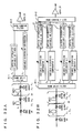
In Fig. 30A, after distributed Raman
amplification (amplification by a pump light source 25),
and amplification by an EDFA 26 are made, dispersion
compensation for a blue band (Λ1) is optimized by a DCF1.
Then, a wavelength band is split by a band split filter
20-1. Dispersion compensation for a red band (Λ2) is
optimized by a variable dispersion compensator 1. An
optical attenuator on the path of the blue band provides
a loss that is almost equal to the loss of the variable
dispersion compensator 1 to the optical signal of the
blue band. This prevents a difference between the
optical intensities of the optical signals of the blue
and the red bands from occurring, when the optical
signals are coupled by a band split filter. Then, the
bands are coupled and output by a band split filter 20-2,
amplified by an EDFA 28, and output to a transmission
line.
In Fig. 30B, the DCFs shown in Fig. 29B are
replaced by variable dispersion compensators. Since a
dispersion value that a variable dispersion compensator
1 arranged for the band Λ1 can compensate for is variable,
a DCF1 in the stage preceding the band split filter may
be arranged depending on need.
The configuration shown in Fig. 30B is similar to
that shown in Fig. 30A except that the number of split
bands is n. Therefore, the same constituent elements
as those shown in Fig. 30A are denoted with the same
reference numerals, and their explanations are omitted.
In Figs. 31A and 31B, the same constituent
elements as those of the above described configuration
examples are denoted with the same reference numerals,
and their explanations are omitted. Figs. 31A and 31B
exemplify the configurations where an inline amplifier
is composed of a dispersion compensating fiber Raman
amplification unit 30 (DCFRA: So called hereinafter is
an amplification unit that makes Raman amplification
by using a DCF as an amplification medium. The DCFRA
makes optical amplification and dispersion
compensation at the same time), and an EDFA 28 in a later
stage. How to split a wavelength band signal, and how
to arrange a dispersion compensation fiber for making
adjustment are the same as those in Figs. 29A and 29B.
The DCFRA 30 is located before a band split filter, and
adjusts the power and the wavelength of pumped light
so as to provide a gain to all of wavelength bands (Λ1,
Λ2 ... Λn). The number of stages of DCFRAs 30 may be 1,
2 or more according to a required gain as shown in Figs.
31A and 31B. In both of Figs. 31A and 31B, a variable
or fixed optical attenuator for compensating for a loss
difference between wavelength bands is arranged
depending on need. Because the dispersion compensation
of the band Λ1 is made in the stage before the band split
filter as described above, a DCF for this band may not
be particularly arranged, and arranged if necessary from
a design viewpoint.
In Figs. 32A and 32B, the same constituent
elements as those shown in Figs. 31A and 31B are denoted
with the same reference numerals, and their explanations
are omitted. Figs. 32A and 32B show the configurations
where the fixed dispersion compensators for the
respective wavelength bands in Figs. 31A and 31B are
replaced by variable dispersion compensators. How to
set a dispersion compensation amount is the same as those
in the configurations shown in Figs. 31A and 31B. However,
the dispersion compensation amount is variable.
Therefore, dispersion compensation with higher
accuracy can be implemented, and besides, the dispersion
amount that changes with time due to a temperature change
in a transmission line can be coped with.
In Fig. 32A, dispersion compensation for a band
Λ1 is made by a DCF1 in an earlier stage or along with
a DCF2 depending on need. Therefore, only a variable
or fixed optical attenuator is arranged.
In Fig. 32B, a variable dispersion compensator 1
is arranged on the path of the band Λ1. Therefore, if
amplification of an optical signal is sufficient, DCF1
and DCF2 may be omitted.
In Figs. 33A and 33B, the same constituent
elements as those shown in Figs. 31A and 31B are denoted
with the same reference numerals, and their explanations
are omitted. Figs. 33A and 33B exemplify the
configurations where DCFRAs are arranged within a band
split compensation unit, or arranged before and within
the band split compensation unit. In Fig. 33A, a
wavelength band is split into a blue band (Λ1) on a short
wavelength side, and a red band (Λ2) on a long wavelength
band by using a band split filter. Dispersion
compensators DCF21 and DCF22, which are arranged within
the band split compensation unit, respectively make
adjustment so that sums d1+d2 and d1+d2+Δd of their
dispersion compensation amounts become optimal
compensation amounts in central channels of the blue
band (Λ1) and the red band (Λ2). Furthermore, their
lengths are set to obtain sufficient Raman amplification
gains on the compensators DCF21 and DCF22 themselves.
Similar to Fig. 27, the dispersion compensation amount
of the DCF may be set as follows: Δd=-S·(1-β)·ΔΛ·L.
Additionally, Raman amplification gains of the DCF21 and
CDF22 can be adjusted so that the optical levels of
wavelength bands become equal. Namely, by adjusting a
Raman amplification gain, a function similar to that
of an optical attenuator can be implemented.
Fig. 33B shows a further expanded configuration
where a wavelength band is split into n bands. A
wavelength band is split into n bands from the short
wavelength side to the long wavelength side, and
dispersion compensators for making adjustment DCF21,
DCF22, ... DCF2n-1, DCF2n, which are intended to optimize
dispersion compensation amounts for the respective
signal bands after being split, are arranged. Dispersion
compensation amounts of the respective dispersion
compensators are set as follows: d2, d2+Δd, ... d2+(n-2) ·
Δd, d2+(n-1)·Δd. The value of Δd may be set in a similar
manner as in Fig. 33A: Δd=-S (1-β) · Δλ · L (Δλ is a
wavelength difference between the central channels of
adjacent wavelength bands). Furthermore, Raman
amplification gains of DCF21, DCF22, ..., DCF2n are
adjusted so that the optical levels of wavelength bands
become equal.
Figs. 34 to 36 exemplify the configurations of a
system using inline amplifiers that make band split
compensation shown in Figs. 29 to 33.
These figures show the examples of a 6-span
transmission. A similar configuration can be
implemented also for spans the number of which is
different. Additionally, these figures show the
examples in the case where a wavelength band is split
into two bands. However, a similar configuration can
be implemented also when a wavelength band is split into
a larger number of bands.
In Fig. 34, band split compensation is made by each
of inline amplifiers 35 according to the above described
preferred embodiments of the present invention, and a
difference of Δd between the dispersion compensation
amounts of split bands is provided. Optical signals of
respective wavelengths, which are output from
transmitters Tx #1 to #n, are coupled by an optical
coupler 40, and output to a transmission line. Over the
transmission line, the optical signal is relayed by the
inline amplifiers 35, and split into the respective
wavelengths by an optical coupler 41. The optical
signals then pass through arbitrarily arranged variable
dispersion compensators 42, and are received by
receivers Rx #1 to #n.
In Figs. 35 and 36, the same constituent elements
as those shown in Fig. 34 are denoted with the same
reference numerals, and their explanations are omitted.
In Fig. 35, band split compensation is made every 2 spans,
and a difference of 2Δd between the dispersion
compensation amounts of split bands is provided. In Fig.
36, band split compensation is made every 3 spans, and
a difference of 3Δd between the dispersion compensation
amounts of split bands is provided. As the configuration
of every 3 spans in Fig. 36 gets closer to that of every
1 span in Fig. 34, residual dispersion in an inline
amplifier is reduced to a smaller value. Therefore,
wavelength degradation caused by chromatic dispersion
and non-linear effects of a fiber is suppressed. However,
since the number of split compensation units becomes
large, the cost and the size increase, which is
disadvantageous from the viewpoint of securing an
optical signal-to-noise ratio (OSNR). Actual
arrangement locations of band split units must be
determined in consideration of such a trade-off in an
entire system.
A preferred embodiment for determining how to set
a dispersion compensation amount in an inline section
is explained below.
For the above described (1) variations of the
length of a transmission line and (2) manufacturing
variations of a chromatic dispersion coefficient, a
chromatic dispersion amount (of all of sections or each
inline section) of an installed fiber transmission line
must be actually measured, and a dispersion compensating
fiber having a chromatic dispersion amount that suits
the measured amount must be installed. However, since
there is the problem of (2) manufacturing variations
of a dispersion slope, strict dispersion compensation
cannot be made for other channels even if chromatic
dispersion is strictly compensated for one channel (such
as a central channel). To make strict dispersion
compensation, a method securing as large dispersion
tolerance as possible in each span, and making strict
dispersion compensation for all of channels at a
receiver side is effective.
Figs. 37A to 37C show a Q penalty (a degradation
amount of a Q value) against residual dispersion (a total
dispersion amount of a transmission line and a
dispersion compensator) in the case of an inline
dispersion compensation ratio DDCL=100 percent and 114
percent in a 600-km SMF transmission (100 km × 6 spans) .
Here, the Q penalty is a difference between a
back-to-back value of a Q value and the Q value after
being transmitted over a transmission line. The Q value
is a value obtained by dividing a sum of a standard
deviation of a sample distribution on the side of "1"
and that on the side of "0" by the amplitude of signals
at the centers of the sample distributions betweem the
sides of "1" and "0", when an eye pattern is obtained
by converting an optical signal waveform into an
electric signal, and a cross section of the eye is
vertically taken at the center of the eye.
Fig. 37A plots the Q penalty against a total
residual dispersion value. Fig.37B shows an eye pattern
when residual dispersion is made zero at a receiving
end in the case where an inline dispersion compensation
amount is set to compensate for a propagation dispersion
amount by 100 percent. Fig. 37C shows an eye pattern
in the case where the inline dispersion compensation
ratio is set to compensate for the propagation
dispersion amount by 114 percent.
As is evident from Figs. 37A to 37C, wavelength
degradation and the Q penalty in the case of the
114-percent over-compensation are smaller than those
in the case of the 100-percent dispersion compensation
(complete wavelength deformation is more advantageous) .
However, the residual dispersion must be strictly made
zero by adjusting the dispersion compensation amount
(DDCR) at a receiving end. Note that, however, DDCT may
be optimized to a different value depending on a
difference in a transmission condition (fiber type,
transmission distance, bit rate, etc.).
Fig. 38 shows a Q penalty characteristic against
an inline dispersion compensation residual amount (the
dispersion amount of a transmission line per span + the
residual dispersion amount of an inline DCF) in the case
where the residual dispersion is made zero by adjusting
the dispersion compensation amount (DDCR) at the
receiving end in each case in a 600-km SMF transmission
(100 km × 6 spans).
It can be verified that over-compensation (an
inline dispersion compensation residual amount is
negative) makes the penalty smaller for an inline DCF.
Furthermore, it is proved that a tolerance
(approximately 400 ps/nm when a 1.5 dB penalty is
allowed), which is considerably larger than the
dispersion tolerance (approximately 70 ps/nm) of a
40-Gb/s signal, can be secured.
Here, a dispersion shift amount ΔD is given by the
following equation.
ΔD (ps/nm)=(dispersion amount per span (ps/nm)) × (1
- dispersion compensation ratio)
Here, dispersion compensation rate = (percentage
of dispersion compensation ratio) / 100. In the case
shown in Fig. 38, (dispersion amount per span (ps/nm))
= (17 (ps/nm/km)) × (100 (km) (per span)) = (1700
(ps/nm)).
Especially, the Q penalty is good in the
neighborhood of -200 ps/nm, where the inline dispersion
compensation amount corresponds to the approximately
114-percent compensation, and an especially good
characteristic is obtained in a range from approximately
105-percent compensation to approximately 120-percent
compensation.
Accordingly, according to the preferred
embodiments of the present invention, dispersion
compensation for all of channels can be effectively made
at low cost and in less size in an ultrahigh-speed
wavelength multiplexing transmission system, even if
manufacturing variations of chromatic
dispersion/dispersion slope of a transmission line and
a DCF are large, if a slope compensation rate of a CCF
is low, or if residual dispersion derived from the
wavelength dependency of a dispersion slope occurs. As
a result, a long-haul transmission can be implemented.
Fig. 39 exemplifies a first configuration
corresponding to a preferred embodiment for optimizing
an inline dispersion compensation amount.
In this figure, the same constituent elements as
those shown in Fig. 34 are denoted with the same
reference numerals, and their explanations are omitted.
If dispersion amounts in central channels in
respective inline relay sections are actually measured
as D1, D2, ..., Dn-1, Dn, dispersion compensation amounts
of inline amplifiers ILA1, ILA2, and ILA(n-1) are set
as follows: dDCL1=- (1+γ) · D1, dDCL2=-(1+γ) · D2, ...,
dDCL(n-1)=- (1+γ)·Dn-1. γ is an over-compensation rate of
a dispersion compensation amount, and typically 0.10
to 0.15 (10 to 15 percent). At a transmitting end, a
dispersion compensation (dispersion compensation in an
optical post-amplifier) DCT (dispersion compensation
amount dDCT) for improving a transmission characteristic
can possibly be arranged (dDCT=0 as a typical value (not
arranged)). To set the residual dispersion (the total
dispersion amount of the transmission line and the
dispersion compensator) to DRD (zero as a typical value)
by making up for the over-compensation of the dispersion
inline amplifier, the dispersion compensation amount
at the receiver side of a reception dispersion
compensator DCR of an optical pre-amplifier is set to
γ (D1 + D2 + ... + Dn-1) - dDCT - Dn + DRD.
If the dispersion amount of spans are equal
(D1=D2= ... =Dn-1=Dn=D), ((n-1)γ-1)D - dDCT + DRD is
obtained. Furthermore, a variable dispersion
compensator for adjusting various types of dispersion
variations or changes with time can possibly be arranged
for each channel or all of channels.
Fig. 40 shows one example of a further specific
configuration.
In this figure, the same constituent elements as
those shown in Fig. 39 are denoted with the same
reference numerals.
In each of inline amplifiers 50, distributed Raman
amplification (DRA) and dispersion compensating fiber
Raman amplification (DCFRA) using a DCF are made. The
number of stages of DCFRA units can possibly be one or
more according to a required gain. In either case, the
length of each DCF is adjusted so that the sum of
dispersion compensation amounts of DCFs becomes equal
to the dispersion compensation amount shown in Fig. 39,
and a required value or larger of the Raman amplification
gain of each DCF can be secured. At that time, an
over-compensation rate γ of the dispersion compensation
amount must be set not to be too large so as to secure
the length which uses the Raman gain at the receiving
end DCF as a required amount.
A repeater 51 at a receiving end has fundamentally
the same configuration as that of the inline amplifier
50. However, an optical amplifier is an optical
pre-amplifier, which makes amplification for detecting
a signal at the receiving end.
Fig. 41 exemplifies the configuration implemented
by combining band split dispersion compensation and
inline over-compensation.
In this figure, the same constituent elements as
those shown in Fig. 40 are denoted with the same
reference numerals, and their explanations are omitted.
For respective inline amplifiers 50, dispersion
compensation fibers DCL1 to DCL(n-1) for making
over-compensation are arranged, and over-compensations
of dDCL1 to dDCLn-1 are made. Furthermore, band split
filters are arranged at a stage after the dispersion
compensation fibers, which respectively make
dispersion compensation for bands.
A dispersion compensator arranged within an
optical pre-amplifier at a receiving end makes
dispersion compensation so that residual dispersion
becomes zero in the dispersion compensation fiber DCR
and the band split dispersion compensator in the stage
after the dispersion compensation fiber. Or, after a
wavelength multiplexed optical signal may be
demultiplexed into optical signals of respective
wavelengths, fine adjustment may be respectively made
for dispersion compensation by arranging variable
dispersion compensators.
According to the present invention, dispersion
compensation can be effectively made at low cost and
with high accuracy in a wavelength multiplexed optical
communication.