EP1349116A1 - Process for modelling a 3d scene - Google Patents
Process for modelling a 3d scene Download PDFInfo
- Publication number
- EP1349116A1 EP1349116A1 EP03290554A EP03290554A EP1349116A1 EP 1349116 A1 EP1349116 A1 EP 1349116A1 EP 03290554 A EP03290554 A EP 03290554A EP 03290554 A EP03290554 A EP 03290554A EP 1349116 A1 EP1349116 A1 EP 1349116A1
- Authority
- EP
- European Patent Office
- Prior art keywords
- depth
- point
- image
- images
- model
- Prior art date
- Legal status (The legal status is an assumption and is not a legal conclusion. Google has not performed a legal analysis and makes no representation as to the accuracy of the status listed.)
- Granted
Links
Images


Classifications
-
- G—PHYSICS
- G06—COMPUTING OR CALCULATING; COUNTING
- G06T—IMAGE DATA PROCESSING OR GENERATION, IN GENERAL
- G06T17/00—Three-dimensional [3D] modelling for computer graphics
-
- G—PHYSICS
- G06—COMPUTING OR CALCULATING; COUNTING
- G06T—IMAGE DATA PROCESSING OR GENERATION, IN GENERAL
- G06T17/00—Three-dimensional [3D] modelling for computer graphics
- G06T17/20—Finite element generation, e.g. wire-frame surface description, tesselation
Definitions
- the invention relates to a 3D scene modelling process and in particular to a process for modelling or for approximating a 3D object by a plane faceted 3D model allowing control of distortion in the synthesized images.
- the invention entails the construction of a 3D model of a scene on the basis of a reference image possessing a depth map.
- Figure 1 represents the surface of an object in 3D space referenced 1.
- An approximation of this object by facetization or triangulation yields a model whose surface is referenced 2.
- a synthesized image is obtained by projecting the model onto a plane 4 from a viewpoint 6.
- the error 3 due to the approximation of the surface of the object to that of the model is conveyed on the image by a 2D distortion referenced 5.
- the figure shows that the error due to the approximation of the surface of a 3D object by planes may be conveyed by an error in the position of its silhouette in the image and more generally by distortion of the shape of the object and of the textures in the image.
- a conventional type of 3D model is the representation by 3D facets.
- One scheme entails an iterative method based on an initial triangulation of the depth map. This method is for example mentioned in the article by Xin CHEN and Francis SCHMITT entitled “Adaptive interval data approximation by constrained surface triangulation", IFIP, Working conference on “Modelling in Computer Graphics", pages 95-113, Genova, Italy, July 93.
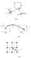
- Figure 2 illustrates a "coarse to fine" type incremental facetization of this kind. More precisely, Figures 2a to 2d correspond to successive iterations, the first iteration, Figure 2a, consisting in the creation of two triangles from the rectangular image. It should be noted that the facetization can be limited to a region of the image, previously polygonized and triangulated so as to constitute the initial model.
- an approximation error map is calculated : this error calculated at all the points of the image corresponds to the difference between the depth value of the pixel and its approximate value through facetization.
- the most poorly approximated point is detected: it is the one having the largest error in terms of absolute value.
- This error is compared with a threshold: if the error is below the threshold, the facetization scheme is terminated; otherwise, the corresponding point is introduced as new vertex of facets, and the facet to which it belongs is composed into three new facets, as is represented in Figure 2b or else into four new facets if the point is situated on an edge, as represented in Figure 2c for the next iteration.
- the aim of the invention is to elevate the aforesaid drawbacks.
- Its subject is a process for modelling a 3D scene defined on the basis of reference images associated with viewpoints and original depth maps, by calculation of approximate depth maps describing a model, characterized in that it comprises the following steps:
- the process is characterized in that the calculation of the minimum and maximum values of the depth of a point I, for a synthesized image, is performed by utilizing the epipolar line corresponding to the point I in this synthesized image, to which are referred the distances corresponding to the maximum permitted distortion.
- the model being defined by a set of elementary regions
- the 3D points whose depth is utilized for the validating step are the points of an elementary region of the model.
- an elementary region is a facet and in that the calculation by iteration is a facetization of the depth maps, the iteration comprising the creation of a new 3D facet vertex of the model or the deletion of a 3D facet vertex of the model depending on whether the process is of the "coarse to fine" or "fine to coarse” type.
- the process, of "coarse to fine” type is characterized in that the iteration comprises a calculation of the poorest approximate value from among the approximate values which relate to a facet and which are outside the spans, and in that the new vertex relates to the point corresponding to this value.
- the set of synthesized images on which the calculation of the errors is performed corresponds to a sample representative of the set of viewpoints using the reference image.
- Another particular characteristic consists in that the set of synthesized images on which the calculation of the errors is performed is composed of images having a number greater than a threshold of 3D points in common with the reference image.
- the maximum permitted distortion is predetermined as a function of a characteristic of an image, for example a luminance gradient.
- the invention also relates to a process for generating images, characterized in that the images are generated on the basis of a modelling of the scene according to the process previously described.
- the invention also relates to a process for compressing data defining a 3D scene, these data relating to reference images in respect of rendition and to associated depth maps, characterized in that the depth maps are modelled by facetization according to the process of Claim 4 and in that the data relating to the reference images and to the depth maps are replaced with data defining the facets.
- the invention also relates to a process for compressing data defining a 3D scene, these data relating to reference images in respect of rendition and to associated depth maps, characterized in that it comprises the modelling steps according to the modelling process of Claim 3, the elementary regions of the model being defined by a partitioning of the depth maps into image blocks, the calculation on approximate depth maps consisting of a modification of a quantization stepsize for these blocks so as to give a quantized depth which is the approximate depth from which the poorly approximate points of the block are determined.
- the modification of the quantization stepsize is carried out in such a way as to obtain the same quantized depth values for a block.
- variable threshold adapted to each pixel and calculated by an auxiliary procedure
- the principle consists in employing a sample representative of the viewpoints which will be synthesized from the model, and in performing the construction of the model while controlling the distortion engendered in the various viewpoints of the sample. More precisely, a maximum fixed value of distortion in the images makes it possible in turn to fix at all points an upper limit on the error of approximating the 3D object by its model. The process thus allows control of the distortion error engendered in the course of rendition.
- the present invention proposes in particular a precise definition of the variable threshold when the space of use of the 3D model resulting from the facetization is known, that is to say when the set of viewpoints which may be generated from the model is known, or else when a sample representative of these viewpoints is known.
- the error of approximation of the depth map created by the facetization procedure for a viewpoint is carried over to the 3D model, and will generally be conveyed by a 2D geometrical distortion in the images for the other viewpoints, synthesized from the model.
- the invention allows a simplification of the depth map in such a way as to obtain a less expensive representation, while controlling the loss of quality of the reconstructed images, here the 2D geometrical distortion.
- the cost of the model is reduced.
- Figure 3 represents the error in the synthesized image, resulting from the error of approximation of the surface of the 3D object, this approximation corresponding to the facetization of the depth map of the reference image, reference 7.
- the depth approximation error, referenced 3 is conveyed, for a lateral view from a viewpoint J, by a 2D distortion error referenced 5.
- the idea is to take into account this distortion error in a 2D image for known viewpoints J or arbitrarily defined viewpoint.
- the quantity of these viewpoints must be sufficient to correspond to a representative sample.
- a maximum error is defined at the level of the 2D image which corresponds to the maximum tolerance of distortion of the image.
- the objective is to model the depth map of the reference image 7 while limiting the distortion which this modelling will engender in the images for the viewpoints J.
- N pairs of values are calculated, corresponding to the N images J which see this point.
- the pair of final values of the point is calculated in such a way as to ensure the quality of rendition over the N images J.
- a map of minimum values and a map of maximum values which correspond, for each pixel of the image, to minimum and maximum depths beyond which a 2D distortion greater than the permitted value appears on at least one image from among the set of viewpoints J. It is these thresholds, deviation between the actual 3D depth and these minimum and maximum values, which are utilized to decide on the creation of new facets.
- the reference images 7 must be sufficiently numerous to make it possible to characterize the object, for example they should be distributed around the object so as to define its various characteristics, or more generally the scene whatever it may be.
- the object or the scene are indeed known only by virtue of these reference viewpoints.
- Figure 4 represents the projections P j and P i respectively onto the selected images 4 relating to the viewpoints J and the reference images 7 relating to the viewpoints I, of a point O of the object 1.
- Figure 4 illustrates the perspective projection 8 of a point of a reference image 7 or image of the representation onto a selected image or rendered image 4. This involves calculating the relation which connects the error in the depth of a point Pi in the representation and the error in the 2D position of the point P J , resulting from the projection of P I onto an image to be reconstructed.
- the coordinates of the point P J , (u j , v j , z j ) are obtained by perspective projection of the pixel Pi(u i , v i , z i ) onto the image J.
- the coefficients a and t correspond to the mathematical operations relating to the changes of reference frames, rotations, translations, and intrinsic camera parameters for the two viewpoints.
- Figure 5 represents a point P J in the image J, arising from the projection of a point P i of the image I. This point does not generally correspond to a pixel of the target image J.
- the tolerated position error for the projected point can for example be that symbolized by the signs [ ] in this figure, where a maximum distance to the projected point is defined. If for example a distortion of less than half a pixel is imposed, these positions correspond to the largest of the values of ⁇ u and ⁇ v which is equal to half the interpixel distance, as well as to the corresponding negative value.
- Each point Pi of the representation is thus projected onto the images J whose reconstruction it participates in.
- a point Pi of the reference image to each image J there corresponds a point Pj associated with a pair (z min (i,j), z max (i,j)).
- the values z min (i,j) and z max (i,j) are calculated for each of these images J.
- the adaptive threshold is employed thus: the approximate depth value z app (i) of each pixel is tested with regard to its membership of the interval [z m (i), z M (i)]. If all the pixels are such that z app (i) belongs to this interval, the depth map is regarded as "a good approximation", and the facetization scheme is halted. If, on the other hand, there exist pixels whose value z app (i) is outside this interval, then the most poorly approximated point Pi is selected and introduced as facet vertex, and the iterative scheme is continued.
- Figures 7a and 7b illustrate the principle of approximating a curve by straight line segments with in the first case a fixed threshold, and in the second an adaptive threshold.
- the curves to be approximated are referenced 9, the intervals or thresholds are referenced 10 and the curves obtained by approximation are referenced 11.
- the original depth map corresponding to the scene and the approximate depth map corresponding to the model are to be compared respectively with the curve to be approximated 9 and with the straight line segments 11.
- the spans allocated to the pixels of the depth map correspond to the variable threshold 10.
- the 3D model defining the scene is described on the basis of elementary regions, for example facets.
- An initial depth map is facetized by iterations, as described in Figure 2 so as to yield an approximate depth map or synthetic depth map.
- the approximate value of each pixel is compared with the span allocated to it.
- the depth allocated to the pixels of the approximate depth map calculated in a known manner, for example by interpolation from the depths of the vertices of the facets, is thus compared with the depth of the corresponding pixels of the original depth map, that defining the scene. If the approximate value of a pixel is outside the span, then its corresponding approximation error is calculated. Next, from among these pixels, the one whose error is the largest is selected. A new facetization is then decided for this elementary region. The process is continued thus for the set of regions of the depth map. The iterations on the depth maps are stopped when, for an approximate depth map, the points all have their approximate depths lying inside the spans allocated to these points.
- an adaptive threshold appears in particular in certain camera motion configurations: for example, when the camera motion is of frontal type, the relief of the zone towards which the camera is directed can be approximated in a coarse manner. Likewise, if the motion corresponds to a rotation, the depth information is no longer useful, the interval is therefore infinite and the representation by facets can be minimal.
- the adaptive threshold is defined at each point on the basis of a fixed tolerated maximum distortion error on all the projected points. This distortion can itself be more or less tolerable:
- the distortion permitted may therefore itself vary as a function of such factors.
- the facetization threshold will then be calculated by taking into account for example, for each point, the maximum distortion value allocated to the pixel closest to the corresponding projected point.
- This maximum distortion value can be calculated automatically as a function of parameters defining the image, for example the luminance gradient.
- any other mode of modelling involving the approximation of the depth values may also be based on the adaptive threshold for controlling the quality of rendition.
- Facetization is a means of compressing the data relating to the depth maps. Indeed, the 3D scene is then no longer defined on the basis of depth values allocated to each pixel but on the basis of data defining the facets.
- Another means which utilizes spatial correlation, carries out in a conventional manner a partitioning of the image into image blocks, a discrete cosine transformation followed by a quantization of the image blocks. It is for example possible to simplify the content of the blocks before transformation, by for example setting all the points of a block to the same depth value if this approximation complies at all points of the block with the calculated minimum and maximum bounds.
- the original depth map is partitioned into image blocks. Each block projected on the object represents the elementary region.
- the approximation of the depth map to define the model is here performed by quantizing the depth values making up the image blocks.
- the quantization stepsize is for example chosen to be increasing during the iterations, the error between the quantized image block and the original image block representing the approximation to the model.
- the span relating to the pixel for which the depth corresponds to the maximum error in the block, is compared with the approximation error to decide on a next iteration.
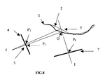
- Figure 8 constitutes a generalization of the scene and of the associated model, which is not necessarily limited to a single object and to a faceted model respectively.
- the list of viewpoints which call upon one and the same region in the rendition that is to say which correspond to the images having pixels in common with one and the same 3D point, or a relevant subset of this list if it is large, is utilized for the calculation of the adaptive threshold.
- the invention relates equally to a "coarse to fine” or “fine to coarse” type model construction.
- the incremental construction of the model of "coarse to fine" type consists, on the basis of a coarse initial model, in enhancing it by introducing at each iteration a new 3D point of the object to be modelled.
- This procedure it is possible, at each iteration, to test the validity of the model for each of the viewpoints of a reference set, by calculating the maximum distortion in the image, and to introduce a new 3D point if it is greater than the threshold.
- the procedure is thus halted when all the reference viewpoints have a distortion at all points which is less than the fixed threshold. It is possible for a viewpoint to be no longer taken into account as soon as the distortion in its image is less than the threshold at all points.
- the incremental construction of the model of "fine to coarse” type consists, on the basis of the model with maximum resolution, in removing points as long as the quality of the model is acceptable.
- the applications of the invention relate inter alia to the construction of models for the synthesization of images or the compression of data.
Landscapes
- Physics & Mathematics (AREA)
- Engineering & Computer Science (AREA)
- Computer Graphics (AREA)
- Geometry (AREA)
- Software Systems (AREA)
- General Physics & Mathematics (AREA)
- Theoretical Computer Science (AREA)
- Image Processing (AREA)
- Image Generation (AREA)
- Testing, Inspecting, Measuring Of Stereoscopic Televisions And Televisions (AREA)
- Processing Or Creating Images (AREA)
Abstract
- predetermination of a maximum permitted distortion (5) on a 2D synthesized image (4), generated by the approximation inherent in the model (2),
- calculation, for a point I of a reference image (7) and on a set of synthesized images (4) representing the 3D point of the scene corresponding to this point I, of the minimum (zi - Δzi 1) and maximum (zi + Δzi 2) depth values of the depth zi of this point I corresponding to this maximum distortion,
- calculation of a span around the depth zi of this point I, dependant on the minimum value of the error Δzi 2 and on the minimum value of the error Δzi 1 among the values calculated for the synthesized images of the set.
Description
- predetermination of a maximum permitted distortion on a 2D synthesized image, generated by the approximation inherent in the model,
- calculation, for a point I of a reference image and on the basis of a set of synthesized images representing the 3D point of the scene corresponding to this point I, of the minimum (zi - Δzi 1) and maximum (zi + Δzi 2) depth values of the depth zi of this point I corresponding to this maximum distortion,
- calculation of a span around the depth zi of this point I, dependant on the minimum value of the error Δzi 2 and on the minimum value of the error Δzi 1 among the values calculated for the synthesized images of the set,
- Figure 1, a scene in 3D space and its modelling,
- Figure 2, a facetization of "coarse to fine" type,
- Figure 3, an error in the synthesized image due to the modelling of an object,
- Figure 4, a perspective projection of a point of a reference image in a synthesized image,
- Figure 5, a point projected onto a synthesized image from the actual scene and a point projected from the model,
- Figure 6, the epipolar line relating to a projected point,
- Figures 7a and 7b, the approximation of a curve by segments, on the basis of a fixed threshold and of a variable threshold respectively.
- Figure 8, an error due to the modelling of a scene.


- depending on whether the point projected, in a rendered image, lies on the silhouette of the 2D object or inside. It may indeed be important to retain an accurate silhouette although the interior distortions are not for example visible.
- depending on whether the point on the image of the representation is situated on a characteristic feature of the object, of geometrical type, for example a rectilinear salient edge, or texturizing edge, whose accuracy it is desired to preserve, or on the contrary in a zone of uniform texture where the defects will be hardly visible.
Claims (13)
- Process for modelling a 3D scene (1) defined on the basis of reference images (7) associated with viewpoints (I) and original depth maps, by calculation of approximate depth maps describing a model, characterized in that it comprises the following steps:and in that it also comprises a step of validating an approximate depth map calculated by iteration, as a function of the approximate depth zapp of 3D points of the corresponding model which relate to points I of the reference image, depending on whether it does or does not belong to the span calculated for these points I.predetermination of a maximum permitted distortion (5) on a 2D synthesized image (4), generated by the approximation inherent in the model (2),calculation, for a point I of a reference image (7) and on the basis of a set of synthesized images (4) representing the 3D point of the scene corresponding to this point I, of the minimum (zi - Δzi 1) and maximum (zi + Δzi 2) depth values of the depth zi of this point I corresponding to this maximum distortion,calculation of a span around the depth zi of this point I, dependant on the minimum value of the error Δzi 2 and on the minimum value of the error Δzi 1 among the values calculated for the synthesized images of the set,
- Process according to Claim 1, characterized in that the calculation of the minimum and maximum values of the depth of a point I, for a synthesized image (4), is performed by utilizing the epipolar line corresponding to the point I in this synthesized image, to which are referred the distances corresponding to the maximum permitted distortion.
- Process according to Claim 1, characterized in that the model being defined by a set of elementary regions, the 3D points whose depth is utilized for the validating step are the points of an elementary region of the model.
- Process according to Claim 3, characterized in that an elementary region is a facet and in that the calculation by iteration is a facetization of the depth maps, the iteration comprising the creation of a new 3D facet vertex of the model or the deletion of a 3D facet vertex of the model depending on whether the process is of the "coarse to fine" or "fine to coarse" type.
- Process according to Claim 4, of "coarse to fine" type, characterized in that the iteration comprises a calculation of the poorest approximate value from among the approximate values which relate to a facet and which are outside the spans, and in that the new vertex relates to the point corresponding to this value.
- Process according to Claim 1, characterized in that the set of synthesized images (4) on which the calculation of the errors is performed corresponds to a sample representative of the set of viewpoints using the reference image (7).
- Process according to Claim 6, characterized in that the set of synthesized images on which the calculation of the errors is performed is composed of images having a number greater than a threshold of 3D points in common with the reference image.
- Process according to Claim 1, characterized in that the maximum permitted distortion is predetermined as a function of a characteristic of an image.
- Process according to Claim 8, characterized in that a characteristic of an image is the luminance gradient.
- Process for generating images, characterized in that the images are generated on the basis of a modelling of the scene according to the process of Claim 1.
- Process for compressing data defining a 3D scene, these data relating to reference images in respect of rendition and to associated depth maps, characterized in that the depth maps are modelled by facetization according to the process of Claim 4 and in that the data relating to the reference images and to the depth maps are replaced with data defining the facets.
- Process for compressing data defining a 3D scene, these data relating to reference images in respect of rendition and to associated depth maps, characterized in that it comprises the modelling steps according to the modelling process of Claim 3, the elementary regions of the model being defined by a partitioning of the depth maps into image blocks, the calculation by iterations on an approximate depth map consisting of a modification of a quantization stepsize for these blocks so as to give a quantized depth which is the approximate depth.
- Process according to Claim 12, characterized in that the modification of the quantization stepsize is an increase in the quantization stepsize such as to obtain the widest quantization stepsize or the same quantized depth values for a block.
Applications Claiming Priority (2)
| Application Number | Priority Date | Filing Date | Title |
|---|---|---|---|
| FR0203663 | 2002-03-25 | ||
| FR0203663A FR2837597A1 (en) | 2002-03-25 | 2002-03-25 | Three-dimensional scene modeling process, involves calculating point of reference image on basis of set of images, of defined minimum and maximum depth values of point depth corresponding to maximum distortion |
Publications (2)
| Publication Number | Publication Date |
|---|---|
| EP1349116A1 true EP1349116A1 (en) | 2003-10-01 |
| EP1349116B1 EP1349116B1 (en) | 2018-07-18 |
Family
ID=27799215
Family Applications (1)
| Application Number | Title | Priority Date | Filing Date |
|---|---|---|---|
| EP03290554.9A Expired - Lifetime EP1349116B1 (en) | 2002-03-25 | 2003-03-07 | Process for modelling a 3d scene |
Country Status (6)
| Country | Link |
|---|---|
| US (1) | US7113635B2 (en) |
| EP (1) | EP1349116B1 (en) |
| JP (1) | JP4376532B2 (en) |
| KR (1) | KR20030077985A (en) |
| CN (1) | CN100337252C (en) |
| FR (1) | FR2837597A1 (en) |
Families Citing this family (36)
| Publication number | Priority date | Publication date | Assignee | Title |
|---|---|---|---|---|
| US7161579B2 (en) | 2002-07-18 | 2007-01-09 | Sony Computer Entertainment Inc. | Hand-held computer interactive device |
| US8313380B2 (en) | 2002-07-27 | 2012-11-20 | Sony Computer Entertainment America Llc | Scheme for translating movements of a hand-held controller into inputs for a system |
| US8686939B2 (en) | 2002-07-27 | 2014-04-01 | Sony Computer Entertainment Inc. | System, method, and apparatus for three-dimensional input control |
| US9393487B2 (en) | 2002-07-27 | 2016-07-19 | Sony Interactive Entertainment Inc. | Method for mapping movements of a hand-held controller to game commands |
| US7760248B2 (en) | 2002-07-27 | 2010-07-20 | Sony Computer Entertainment Inc. | Selective sound source listening in conjunction with computer interactive processing |
| US8570378B2 (en) | 2002-07-27 | 2013-10-29 | Sony Computer Entertainment Inc. | Method and apparatus for tracking three-dimensional movements of an object using a depth sensing camera |
| US9474968B2 (en) | 2002-07-27 | 2016-10-25 | Sony Interactive Entertainment America Llc | Method and system for applying gearing effects to visual tracking |
| US9682319B2 (en) | 2002-07-31 | 2017-06-20 | Sony Interactive Entertainment Inc. | Combiner method for altering game gearing |
| CN1739119A (en) * | 2003-01-17 | 2006-02-22 | 皇家飞利浦电子股份有限公司 | Full Depth Map Acquisition |
| US9177387B2 (en) | 2003-02-11 | 2015-11-03 | Sony Computer Entertainment Inc. | Method and apparatus for real time motion capture |
| US8072470B2 (en) * | 2003-05-29 | 2011-12-06 | Sony Computer Entertainment Inc. | System and method for providing a real-time three-dimensional interactive environment |
| US7660436B2 (en) * | 2003-06-13 | 2010-02-09 | Sarnoff Corporation | Stereo-vision based imminent collision detection |
| US8547401B2 (en) | 2004-08-19 | 2013-10-01 | Sony Computer Entertainment Inc. | Portable augmented reality device and method |
| KR100682935B1 (en) * | 2005-02-17 | 2007-02-15 | 삼성전자주식회사 | Method and device for removing abnormal samples from database |
| US20060233461A1 (en) * | 2005-04-19 | 2006-10-19 | Honeywell International Inc. | Systems and methods for transforming 2d image domain data into a 3d dense range map |
| WO2007130122A2 (en) * | 2006-05-05 | 2007-11-15 | Thomson Licensing | System and method for three-dimensional object reconstruction from two-dimensional images |
| US8781151B2 (en) | 2006-09-28 | 2014-07-15 | Sony Computer Entertainment Inc. | Object detection using video input combined with tilt angle information |
| US8310656B2 (en) | 2006-09-28 | 2012-11-13 | Sony Computer Entertainment America Llc | Mapping movements of a hand-held controller to the two-dimensional image plane of a display screen |
| USRE48417E1 (en) | 2006-09-28 | 2021-02-02 | Sony Interactive Entertainment Inc. | Object direction using video input combined with tilt angle information |
| US20080158254A1 (en) * | 2006-12-29 | 2008-07-03 | Hong Jiang | Using supplementary information of bounding boxes in multi-layer video composition |
| KR101483659B1 (en) * | 2008-07-11 | 2015-01-16 | 삼성디스플레이 주식회사 | Method for displaying 3 dimensional image, and display device for performing the same |
| KR101556593B1 (en) * | 2008-07-15 | 2015-10-02 | 삼성전자주식회사 | Image processing method |
| US8180167B2 (en) * | 2008-07-16 | 2012-05-15 | Seiko Epson Corporation | Model-based error resilience in data communication |
| US8233664B2 (en) * | 2008-11-12 | 2012-07-31 | Eastman Kodak Company | Determining relative depth of points in multiple videos |
| US8248410B2 (en) * | 2008-12-09 | 2012-08-21 | Seiko Epson Corporation | Synthesizing detailed depth maps from images |
| US8194097B2 (en) * | 2008-12-12 | 2012-06-05 | Seiko Epson Corporation | Virtual masking using rigid parametric modeling |
| US8705852B2 (en) | 2011-01-27 | 2014-04-22 | Samsung Electronics Co., Ltd. | Image processing apparatus and method for defining distortion function for synthesized image of intermediate view |
| WO2013077510A1 (en) * | 2011-11-23 | 2013-05-30 | 에스케이플래닛 주식회사 | Method and device for measuring stereoscopic effect, stability or fallibility of three-dimensional stereoscopic image |
| KR101332628B1 (en) * | 2011-11-23 | 2013-11-25 | 에스케이플래닛 주식회사 | Method and system for measuring a quality of three-dimensional image |
| EP2728306A1 (en) * | 2012-11-05 | 2014-05-07 | Hexagon Technology Center GmbH | Method and device for determining three-dimensional coordinates of an object |
| JP2015033047A (en) * | 2013-08-05 | 2015-02-16 | Kddi株式会社 | Depth estimation device employing plural cameras |
| CN104768018B (en) * | 2015-02-04 | 2016-09-21 | 浙江工商大学 | A kind of quick view prediction method based on depth map |
| KR101768532B1 (en) * | 2016-06-08 | 2017-08-30 | 주식회사 맥스트 | System and method for video call using augmented reality |
| US11245888B2 (en) * | 2018-03-19 | 2022-02-08 | Ricoh Company, Ltd. | Information processing apparatus, image capture apparatus, image processing system, and method of processing a plurality of captured images of a traveling surface where a moveable apparatus travels |
| CN108961404B (en) * | 2018-06-27 | 2022-02-08 | 衡阳师范学院 | A method and system for building an irregular model by building blocks |
| CN113096254B (en) * | 2021-04-23 | 2023-09-22 | 北京百度网讯科技有限公司 | Object rendering method and device, computer equipment and media |
Citations (3)
| Publication number | Priority date | Publication date | Assignee | Title |
|---|---|---|---|---|
| EP0526881A2 (en) * | 1991-08-06 | 1993-02-10 | Canon Kabushiki Kaisha | Three-dimensional model processing method, and apparatus therefor |
| US6198486B1 (en) * | 1998-09-23 | 2001-03-06 | Intel Corporation | Method of using a hybrid error metric for multi-resolution mesh generation |
| FR2798761A1 (en) * | 1999-09-17 | 2001-03-23 | Thomson Multimedia Sa | METHOD FOR CONSTRUCTING A 3D SCENE MODEL BY ANALYZING IMAGE SEQUENCE |
Family Cites Families (5)
| Publication number | Priority date | Publication date | Assignee | Title |
|---|---|---|---|---|
| FR2724033B1 (en) * | 1994-08-30 | 1997-01-03 | Thomson Broadband Systems | SYNTHESIS IMAGE GENERATION METHOD |
| IL113496A (en) * | 1995-04-25 | 1999-09-22 | Cognitens Ltd | Apparatus and method for recreating and manipulating a 3d object based on a 2d projection thereof |
| US5905500A (en) * | 1997-02-19 | 1999-05-18 | Seiko Epson Corporation | Method and apparatus for adaptive nonlinear projective rendering |
| JP3906615B2 (en) * | 1999-10-29 | 2007-04-18 | 株式会社明電舎 | Recursive corresponding point search method, three-dimensional position measurement method using the same, these devices, and recording medium |
| JP4192377B2 (en) * | 1999-12-27 | 2008-12-10 | コニカミノルタセンシング株式会社 | Data reduction method and data reduction apparatus for three-dimensional shape data |
-
2002
- 2002-03-25 FR FR0203663A patent/FR2837597A1/en active Pending
-
2003
- 2003-03-07 EP EP03290554.9A patent/EP1349116B1/en not_active Expired - Lifetime
- 2003-03-20 KR KR10-2003-0017419A patent/KR20030077985A/en not_active Ceased
- 2003-03-24 JP JP2003080969A patent/JP4376532B2/en not_active Expired - Fee Related
- 2003-03-25 CN CNB031073883A patent/CN100337252C/en not_active Expired - Fee Related
- 2003-03-25 US US10/396,182 patent/US7113635B2/en not_active Expired - Lifetime
Patent Citations (3)
| Publication number | Priority date | Publication date | Assignee | Title |
|---|---|---|---|---|
| EP0526881A2 (en) * | 1991-08-06 | 1993-02-10 | Canon Kabushiki Kaisha | Three-dimensional model processing method, and apparatus therefor |
| US6198486B1 (en) * | 1998-09-23 | 2001-03-06 | Intel Corporation | Method of using a hybrid error metric for multi-resolution mesh generation |
| FR2798761A1 (en) * | 1999-09-17 | 2001-03-23 | Thomson Multimedia Sa | METHOD FOR CONSTRUCTING A 3D SCENE MODEL BY ANALYZING IMAGE SEQUENCE |
Non-Patent Citations (2)
| Title |
|---|
| FITZGIBBON A W ET AL: "Automatic 3D model construction for turn-table sequences", LECTURE NOTES IN COMPUTER SCIENCE, SPRINGER VERLAG, NEW YORK, NY, US, 6 June 1998 (1998-06-06), pages 155 - 170, XP002121436, ISSN: 0302-9743 * |
| X,CHEN;F. SCHMIT: "Adaptive range data approximaion by constrained surface triangulation", WORK. CONF. MODELING IN COMPUTER GRAPHICS, 1 July 1993 (1993-07-01), Genova(IT), pages 95 - 113, XP008010452 * |
Also Published As
| Publication number | Publication date |
|---|---|
| US20030179194A1 (en) | 2003-09-25 |
| CN1447288A (en) | 2003-10-08 |
| KR20030077985A (en) | 2003-10-04 |
| CN100337252C (en) | 2007-09-12 |
| FR2837597A1 (en) | 2003-09-26 |
| EP1349116B1 (en) | 2018-07-18 |
| JP4376532B2 (en) | 2009-12-02 |
| JP2003323631A (en) | 2003-11-14 |
| US7113635B2 (en) | 2006-09-26 |
Similar Documents
| Publication | Publication Date | Title |
|---|---|---|
| US7113635B2 (en) | Process for modelling a 3D scene | |
| EP2592596B1 (en) | Compression of texture rendered wire mesh models | |
| US8849010B2 (en) | Method and system for rectifying images | |
| CN1186746C (en) | A Method of Constructing a 3D Scene Model by Analyzing Image Sequences | |
| CN119165652A (en) | A high-precision three-dimensional reconstruction method and system for optical lenses | |
| CN116805356A (en) | Building model construction method, building model construction equipment and computer readable storage medium | |
| Fua et al. | Reconstructing surfaces from unstructured 3d points | |
| JP2012208759A (en) | Method and program for improving accuracy of three-dimensional shape model | |
| CN119991789A (en) | A method and system for three-dimensional posture recognition of conductor tension clamp based on structured light | |
| Kim et al. | Textureme: High-quality textured scene reconstruction in real time | |
| CN111028349B (en) | Hierarchical construction method suitable for rapid visualization of massive three-dimensional live-action data | |
| CN117168351A (en) | An active 3D measurement method of geometric parameters | |
| Armando et al. | Adaptive mesh texture for multi-view appearance modeling | |
| KR20060015755A (en) | Method and apparatus for representing image sequence using 3D model | |
| US20070064099A1 (en) | Method of representing a sequence of pictures using 3d models, and corresponding devices and signals | |
| Kiani et al. | Planelets—A piecewise linear fractional model for preserving scene geometry in intra-coding of indoor depth images | |
| CN1666234B (en) | topological image mode | |
| Liu et al. | Cracks-suppression perceptual geometry coding for dynamic point clouds | |
| Rasmuson et al. | User-guided 3D reconstruction using multi-view stereo | |
| JP5024962B2 (en) | Multi-view distance information encoding method, decoding method, encoding device, decoding device, encoding program, decoding program, and computer-readable recording medium | |
| CN117765010B (en) | Tetrahedron surface labeling Mesh construction method and system combined with UAV segmentation image | |
| US12412313B2 (en) | Mesh geometry coding | |
| Tao et al. | Point cloud projection based light-to-medium G-PCC-1 hole distortion repair method for colored point cloud | |
| WO2006062508A1 (en) | Dynamic warp map generation system and method | |
| Sarti et al. | Image-based surface modeling: a multi-resolution approach |
Legal Events
| Date | Code | Title | Description |
|---|---|---|---|
| PUAI | Public reference made under article 153(3) epc to a published international application that has entered the european phase |
Free format text: ORIGINAL CODE: 0009012 |
|
| AK | Designated contracting states |
Kind code of ref document: A1 Designated state(s): AT BE BG CH CY CZ DE DK EE ES FI FR GB GR HU IE IT LI LU MC NL PT SE SI SK TR |
|
| AX | Request for extension of the european patent |
Extension state: AL LT LV MK RO |
|
| 17P | Request for examination filed |
Effective date: 20040325 |
|
| AKX | Designation fees paid |
Designated state(s): DE FR GB |
|
| RAP1 | Party data changed (applicant data changed or rights of an application transferred) |
Owner name: THOMSON LICENSING |
|
| RAP1 | Party data changed (applicant data changed or rights of an application transferred) |
Owner name: THOMSON LICENSING |
|
| 17Q | First examination report despatched |
Effective date: 20130417 |
|
| GRAP | Despatch of communication of intention to grant a patent |
Free format text: ORIGINAL CODE: EPIDOSNIGR1 |
|
| INTG | Intention to grant announced |
Effective date: 20180219 |
|
| GRAS | Grant fee paid |
Free format text: ORIGINAL CODE: EPIDOSNIGR3 |
|
| GRAA | (expected) grant |
Free format text: ORIGINAL CODE: 0009210 |
|
| AK | Designated contracting states |
Kind code of ref document: B1 Designated state(s): DE FR GB |
|
| REG | Reference to a national code |
Ref country code: GB Ref legal event code: FG4D |
|
| REG | Reference to a national code |
Ref country code: DE Ref legal event code: R096 Ref document number: 60351325 Country of ref document: DE |
|
| REG | Reference to a national code |
Ref country code: DE Ref legal event code: R097 Ref document number: 60351325 Country of ref document: DE |
|
| PLBE | No opposition filed within time limit |
Free format text: ORIGINAL CODE: 0009261 |
|
| STAA | Information on the status of an ep patent application or granted ep patent |
Free format text: STATUS: NO OPPOSITION FILED WITHIN TIME LIMIT |
|
| 26N | No opposition filed |
Effective date: 20190423 |
|
| GBPC | Gb: european patent ceased through non-payment of renewal fee |
Effective date: 20190307 |
|
| PG25 | Lapsed in a contracting state [announced via postgrant information from national office to epo] |
Ref country code: GB Free format text: LAPSE BECAUSE OF NON-PAYMENT OF DUE FEES Effective date: 20190307 |
|
| PGFP | Annual fee paid to national office [announced via postgrant information from national office to epo] |
Ref country code: DE Payment date: 20200311 Year of fee payment: 18 |
|
| PGFP | Annual fee paid to national office [announced via postgrant information from national office to epo] |
Ref country code: FR Payment date: 20200331 Year of fee payment: 18 |
|
| REG | Reference to a national code |
Ref country code: DE Ref legal event code: R119 Ref document number: 60351325 Country of ref document: DE |
|
| PG25 | Lapsed in a contracting state [announced via postgrant information from national office to epo] |
Ref country code: DE Free format text: LAPSE BECAUSE OF NON-PAYMENT OF DUE FEES Effective date: 20211001 Ref country code: FR Free format text: LAPSE BECAUSE OF NON-PAYMENT OF DUE FEES Effective date: 20210331 |