EP1348950A2 - Air/fuel ratio detection apparatus - Google Patents
Air/fuel ratio detection apparatus Download PDFInfo
- Publication number
- EP1348950A2 EP1348950A2 EP03007029A EP03007029A EP1348950A2 EP 1348950 A2 EP1348950 A2 EP 1348950A2 EP 03007029 A EP03007029 A EP 03007029A EP 03007029 A EP03007029 A EP 03007029A EP 1348950 A2 EP1348950 A2 EP 1348950A2
- Authority
- EP
- European Patent Office
- Prior art keywords
- solid electrolyte
- electrolyte layer
- electrode
- voltage
- fuel ratio
- Prior art date
- Legal status (The legal status is an assumption and is not a legal conclusion. Google has not performed a legal analysis and makes no representation as to the accuracy of the status listed.)
- Granted
Links
Images




Classifications
-
- G—PHYSICS
- G01—MEASURING; TESTING
- G01N—INVESTIGATING OR ANALYSING MATERIALS BY DETERMINING THEIR CHEMICAL OR PHYSICAL PROPERTIES
- G01N27/00—Investigating or analysing materials by the use of electric, electrochemical, or magnetic means
- G01N27/26—Investigating or analysing materials by the use of electric, electrochemical, or magnetic means by investigating electrochemical variables; by using electrolysis or electrophoresis
- G01N27/27—Association of two or more measuring systems or cells, each measuring a different parameter, where the measurement results may be either used independently, the systems or cells being physically associated, or combined to produce a value for a further parameter
-
- G—PHYSICS
- G01—MEASURING; TESTING
- G01N—INVESTIGATING OR ANALYSING MATERIALS BY DETERMINING THEIR CHEMICAL OR PHYSICAL PROPERTIES
- G01N27/00—Investigating or analysing materials by the use of electric, electrochemical, or magnetic means
- G01N27/26—Investigating or analysing materials by the use of electric, electrochemical, or magnetic means by investigating electrochemical variables; by using electrolysis or electrophoresis
- G01N27/416—Systems
- G01N27/417—Systems using cells, i.e. more than one cell and probes with solid electrolytes
- G01N27/419—Measuring voltages or currents with a combination of oxygen pumping cells and oxygen concentration cells
Definitions
- the present invention relates to an air/fuel ratio detection apparatus for determining air/fuel ratio of, for example, automotive engines from oxygen concentration or the like of exhaust gas.
- automotive engines and the like are provided with an air/fuel ratio sensor (oxygen sensor) in the middle of exhaust pipe or the like for detecting oxygen concentration or the like of exhaust gas.
- an air/fuel ratio sensor oxygen sensor
- an air/fuel ratio detection apparatus for a gas comprising:
- an air/fuel ratio detection apparatus has a heater portion that has an elongate cylindrical shape.
- a heater portion that has an elongate cylindrical shape.
- This elongate cylindrical shape can provide more freedom in selecting the direction of installation of the air/fuel ratio detection apparatus. This makes it possible to detect oxygen concentration and the like of exhaust gas with a stable accuracy. Furthermore, it becomes possible to have an enlarged heating surface area of the heater portion for heating the solid electrolyte layer.
- the air/fuel ratio detection apparatus is clearly made by its elongate cylindrical shape to have a smaller size, as compared with conventional plate-like air/fuel ratio detection apparatuses. Furthermore, it is possible to arrange the first to third electrodes such that the first electrode is opposed to the second and third electrodes with an interposal of a solid electrolyte layer in a radial direction. With this, it becomes possible to provide the first to third electrodes with a large electrode surface and with a short distance therebetween to reduce electrical resistance. Furthermore, it is possible to make the air/fuel ratio detection apparatus smaller in diameter. Still furthermore, it is possible to form a diffusion layer on the peripheral side of the solid electrolyte layer. With this, it becomes possible to easily correct deviation in porosity of the diffusion layer and to improve yield in the production.
- first and second voltages first voltage ⁇ second voltage
- first and third electrodes respectively between the first and second electrodes and between the first and third electrodes
- an air/fuel ratio detection apparatus air/fuel ratio or oxygen sensor
- air/fuel ratio or oxygen sensor air/fuel ratio or oxygen sensor
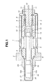
- a casing of the first air/fuel ratio sensor As is seen from Fig. 1, designated by numeral 1 is a casing of the first air/fuel ratio sensor.
- This casing 1 comprises (a) cylindrical holder 2 having external threaded portion 2A, (b) cylindrical cap 3 that is integrally secured to a base portion of holder 2, and (c) guiding tube 4 that is disposed to be concentric with cap 3 and is positioned between the after-mentioned sealing cap 10 and holder 2.
- Each of holder 2, cap 3 and guiding tube 4 can be made of a metal material such as stainless steel.
- External threaded portion 2A is threadedly engaged with the exhaust pipe such that the after-mentioned air/fuel ratio detection device 21 protrudes into the inside space of exhaust pipe.
- Insulating support 5 is an insulating support that is disposed in a void space defined by holder 2 with an interposal of metal seal ring 6.
- Insulating support 5 has a generally cylindrical shape and a cylindrical opening for receiving air/fuel ratio detection device 21 and is made of a ceramic material (e.g., aluminum oxide (Al 2 O 3 )).
- air/fuel ratio detection device 21 is secured to the inner cylindrical wall of insulating support 5 by an inorganic bond or the like.
- air/fuel ratio detection device 21 is positioned at a proper position in casing 1 by insulating support 5 and is electrically and thermally insulated by insulating support 5.
- Designated by numerals 7, 8 are insulating cylindrical members disposed in the inside space of guiding tube 4.
- Each of these cylindrical members 7, 8 is made of a ceramic material (e.g., aluminum oxide (hereinafter referred to as alumina)) and keeps the after-mentioned contact plates 13, 14 and the like in an insulated condition against the casing 1.
- alumina aluminum oxide
- Designated by numeral 9 is a spring (as an elastic member) that is positioned in the inside of casing 1 and is sandwiched between insulating support 5 and insulating cylindrical member 7.
- Spring 9 biases insulating support 5 toward holder 2 and serves to prevent a direct transmission of vibration, shock and the like from an outside to air/fuel ratio detection device 21 through casing 1.
- Seal cap 10 is a seal cap for closing a base end of cap 3.
- Seal cap 10 has a stepped cylindrical shape and is made of a heat-resistant resin material (e.g., polytetrafluoroethylene (PTFE)). Insulating cylindrical members 7, 8 and the like are positioned at proper positions in the inside of casing 1 with a biasing force of spring 9.
- PTFE polytetrafluoroethylene
- Lead wires 11, 11 for detecting air/fuel ratio and lead wires 12, 12 (only one is shown in Fig. 1) for energizing the heater portion are inserted into the seal cap 10. Lead wires 11, 11 are electrically connected with contact plates 13, 13, and lead wires 12, 12 are electrically connected with contact plates 14, 14.
- Designated by numeral 15 is a protector formed on holder 2 of casing 1.
- Protector 15 is formed into a cylindrical shape by using a heat-resistant metal plate or the like.
- Protector 15 is attached at its base portion to holder 2 to cover an end portion of air/fuel ratio detection device 21. With this, the end portion of protector 15 protrudes from holder 2 in its axial direction.
- Protector 15 is formed at its end portion with a plurality of openings 15A for guiding the exhaust gas (flowing through the exhaust pipe) toward the end portion of air/fuel ratio detection device 21.
- Air/fuel ratio detection device 21 is fixed in the inside of holder 2 by insulating support 5, and the end portion of device 21 protrudes from holder 2 in the axial direction. As shown in Figs. 2 and 6, air/fuel ratio detection device 21 comprises heater portion 22, solid electrolyte layer 27 and diffusion layer 34.
- heater portion 22 (having an elongate cylindrical shape) comprises (a) core pipe 23 formed into a hollow cylindrical shape by a ceramic material (e.g., alumina), (b) heater pattern, and (c) insulating, heater covering layer 25.
- a ceramic material e.g., alumina
- heater pattern 24 is formed on the periphery of core pipe 23 by a curved surface printing or the like.
- Heater pattern 24 has a pair of leads 24A, 24A extending in the axial direction of core pipe 23.
- Heater covering layer 25 is formed on the periphery of core pipe 23 by a thick film printing using a ceramic material (e.g., alumina) for the purpose of protecting heater pattern 24 together with its leads 24a.
- Core pipe 23 is formed into an elongate cylindrical shape by injection molding of a ceramic material (e.g., alumina), for example, to have an outer diameter of about 3-4 mm and an axial length of about 50-60 mm.
- Core pipe 23 has cylindrical hole 23A extending in the axial direction. This hole 23A reduces the volume of core pipe 23 and thereby serves to reduce heat capacity of core pipe 23.
- Core pipe 23 may be formed by extrusion besides the above-mentioned injection molding.
- core pipe 23 may have a solid structure as opposed to the above-mentioned hollow structure.
- Heater pattern 24 is made of an exothermic conductive material (e.g., platinum mixed with 10 wt% of alumina). Each lead 24A is connected at the base end portion of core pipe 23 with each contact plate 14, as shown in Fig. 1. Electricity is supplied to heater pattern 24 from the after-mentioned power source 34 through leads 12, contact plates 14 and leads 24A, thereby heating heater portion 22 at a temperature of about 650-800°C.
- an exothermic conductive material e.g., platinum mixed with 10 wt% of alumina.
- Heater covering layer 25 is formed into a cylindrical, porous, insulating layer using a ceramic material (e.g., alumina). Solid electrolyte layer 27 and inner electrode 28 are laminated on the periphery of heater covering layer 25 by a curved surface printing or the like.
- a ceramic material e.g., alumina
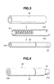
- plug 26 is a plug. Similar to core pipe 23, plug 26 is made of a ceramic material (e.g., alumina). Plug 26 is fit into a base end of the cylindrical hole 23A to close the cylindrical hole 23A. Cylindrical hole 23A of core pipe 23 can be used as a centering hole for conducing a curved surface printing of the after-mentioned solid electrolyte layer 27, protecting layer 33, diffusion layer 34 and the like.
- a ceramic material e.g., alumina
- Solid electrolyte layer 27 is an oxygen ion conductive solid electrolyte layer.
- Solid electrolyte layer 27 is formed on the periphery of heater covering layer 25 of heater portion 22 by using a curved surface printing technique or the like.
- solid electrolyte layer 27 can be formed into a cylindrical shape by conducting a thick film printing of a paste on the periphery of heater covering layer 25.
- This paste can be made from a mixture (a so-called yttria-stabilized zirconia (YSZ)) of 95mol% of a zirconia (ZrO 2 ) powder and 5mol% of an yttria (Y 2 O 3 ) powder.
- YSZ yttria-stabilized zirconia
- Solid electrolyte layer 27 has a thickness of, for example, about 50-100 ⁇ m and transports oxygen ions therethrough between electrodes 28, 29 and between electrodes 28, 31. With this, solid electrolyte layer 27 generates the after-mentioned Nernst voltages Vnl, Vnt, Vnr according to air-fuel ratio.
- Designated by numeral 28 is an inner electrode (first electrode) that is positioned between heater covering layer 25 of heater portion 22 and solid electrolyte layer 27 and that is formed on the inner surface of solid electrolyte layer 27.
- inner electrode 28 can be formed on the periphery of heater covering layer 25 (porous insulating layer) by conducting a curved surface printing, prior to curved surface printing of solid electrolyte layer 27.
- inner electrode 28 can be formed into a cylindrical electrode to have a predetermined length in the axial direction of heater covering layer 25 or solid electrolyte layer 27 by conducting a curved surface printing in which a paste containing the after-mentioned noble metal material 41 and ceramic grains 42 is applied to the periphery of heater covering layer 25.
- inner electrode 28 is opposed at its one side (leading end side) in the axial direction with the after-mentioned measuring electrode 29 in the radial direction of solid electrolyte layer 27 and is opposed at its the other side (base end side) in the axial direction with the after-mentioned reference electrode 31 in the radial direction of solid electrolyte layer 27.
- Inner electrode 28 has a pair of leads 28A (only one is shown in Fig. 5A) extending toward the base end of heater portion 22 in the axial direction of heater covering layer 25.
- Solid electrolyte layer 27 is formed on the periphery of heater covering layer 25 by curved surface printing in a manner to fully surround inner electrode 28 from outside except its leads 28A.
- measuring electrode 29 is a measuring electrode (second electrode) that is formed on the periphery of solid electrolyte layer 27 at a position close to the leading end of heater portion 22. As shown in Fig. 2, measuring electrode 29 is at a position to interpose solid electrolyte layer 27 between measuring electrode 29 and inner electrode 28 and thereby constitutes measuring cell 30 as a first pumping cell.
- reference electrode 31 is a reference electrode (third electrode) that is formed on the periphery of solid electrolyte layer 27 at a position away from measuring electrode 29 in the axial direction of heater portion 22. As shown in Fig. 2, reference electrode 31 is a position to interpose solid electrolyte layer 27 between reference electrode 31 and inner electrode 28 and thereby constitutes reference cell 32 as a second pumping cell.
- Measuring electrode 29 and reference electrode 31 can be formed on the periphery of solid electrolyte layer 27 by conducting a curved surface printing using a conductive paste of platinum or the like to have a printing pattern shown in Fig. 5.
- Their leads 28A, 31A extend toward the base end of heater portion 22.
- Each lead 28A of inner electrode 28, lead 29A of measuring electrode 29 and lead 31A of reference electrode 31 are connected at the base end side of air/fuel ratio detection device 21 with corresponding contact plate 13 and lead 11. As shown in Fig. 2, working voltage Va (first voltage) is applied between inner electrode 28 and measuring electrode 29 from the after-mentioned direct current power source 36.
- Working voltage Vb (second voltage) is applied between inner electrode 28 and reference electrode 31 from the after-mentioned direct current power source 39.
- reference electrode 31 On the side of reference cell 32, reference electrode 31 becomes a cathode for conducting reactions shown in the after-mentioned reaction formulas (1) and (3), and inner electrode 28 becomes an anode. With this, oxygen is attracted from reference electrode 31 toward inner electrode 28, as mentioned hereinafter.
- reference electrode 29 On the other hand, on the side of measuring cell 30, under a lean air/fuel ratio condition ( ⁇ >1), reference electrode 29 becomes cathode for conducting the reaction shown in reaction formula (1), and inner electrode 28 becomes anode to attract oxygen. In contrast, under a rich air/fuel ratio condition ( ⁇ 1), reference electrode 31 turns into anode, and inner electrode 28 serves as cathode.
- protecting layer 33 is a protecting layer for covering a part of solid electrolyte layer 27 as well as reference electrode 31. As shown in Figs. 2 and 5, protecting layer 33 is formed into a cylindrical body to have a thickness of, for example, about 30-100 ⁇ m by a paste of alumina powder and magnesium oxide (MgO) powder and then by applying the paste to the peripheries of solid electrolyte layer 27 and heater covering layer 25 using a curved surface printing.
- MgO magnesium oxide
- the thus formed protecting layer 33 is made to have a porous structure having a porosity higher than that of the after-mentioned diffusion layer 34.
- Protecting layer 33 covers solid electrolyte layer 27 from outside except its leading end portion having thereon measuring electrode 29.
- Protecting layer 33 has a function of protecting heater covering layer 25, solid electrolyte layer 27 and reference electrode 31. A part of the exhaust gas flowing around protecting layer 33 is allowed to pass through protecting layer 33 (having a high porosity) toward reference electrode 31.
- diffusion layer 34 is a diffusion layer made of a porous material for covering solid electrolyte layer 27 and measuring electrode 29 from outside.
- diffusion layer 34 can be formed into a cylindrical body to have a thickness of, for example, about 30-100 ⁇ m by applying a paste of alumina powder to the periphery of the leading end portion of solid electrolyte layer 27. It is optional to add a predetermined amount of zirconia powder to the alumina powder paste in the preparation of diffusion layer 34.
- Diffusion layer 34 is formed to have a porous structure having finer pores as compared with those of protecting layer 33 and thereby has a function to allow a part of the exhaust gas flowing around diffusion layer 34 to pass through diffusion layer 34 toward measuring electrode 29. Transmission of the exhaust gas (gas diffusion resistance) can be adjusted by changing the thickness of diffusion layer 34. As shown in Fig. 2, diffusion layer 34 is positioned to cover the leading end side of heater portion 22. Therefore, it is easily possible to adjust thickness of diffusion layer 34 from outside following the removal of protector 15.
- diffusion layer 34 can be formed by plasma spraying to cover the periphery of the leading end side of solid electrolyte layer 27 using a porous ceramic material, for example, of alumina.
- heater power source 35 is a heater power source provided outside of casing 1. As is shown in Fig. 2, heater power source 35 is connected with heater pattern 24 through lead 12 and the like. Heater power source 35 heats heater portion 22 at a temperature of about 650-800°C by applying voltage to heater pattern 24 of heater portion 22.
- Designated by numeral 36 is a direct current power source (first voltage applying device) provided outside of casing 1. As is shown in Fig. 2, direct current power source 36 is connected with inner electrode 28 and measuring electrode 29 through lead 11, thereby applying working voltage Va (first voltage) between electrodes 28, 29.
- Working voltage Va of direct current power source 36 may be kept at a constant voltage (e.g., about 450mV) or varied according to need.
- Designated by numeral 37 is an ammeter disposed between and connected with direct current power source 36 and measuring electrode 29.
- Ammeter 37 detects diffusion limiting current Im (outputted from measuring electrode 29) corresponding to air/fuel ratio, as shown by characteristic line 38 of Fig. 8.
- Designated by numeral 39 is a direct current power source (second voltage applying device) provided outside of casing 1.
- direct current power source 39 is connected with inner electrode 28 and reference electrode 31 through lead 11, thereby applying working voltage Vb (second voltage) between electrodes 28, 31.
- working voltage Vb of direct current power source 39 is kept at a constant voltage (e.g., about 1.6V). This working voltage Vb becomes higher than working voltage Va of direct current power source 36, and may be adjusted according to need.
- Working voltage Va of direct current power source 36 and working voltage Vb of direct current power source 39 are adjusted in advance such that the amount of oxygen absorbed into void spaces 43 (oxygen receiving chambers) of inner electrode 28 due to the after-mentioned combined pumping voltage Upb is larger than the amount of oxygen absorbed out of void spaces 43 of inner electrode 28 due to the after-mentioned pumping voltage Upa.
- working voltages Va and Vb are adjusted to satisfy the expression (7).
- the signal outputted as diffusion limiting current Im from measuring electrode 29 is detected by ammeter 37 as the detected signal that changes according to air/fuel ratio, as shown by characteristic line 38 of Fig. 8.
- Inner electrode 28 is formed of noble metal material 41 (e.g., platinum), ceramic grains 42, and void spaces 43.
- noble metal material 41 e.g., platinum
- ceramic grains 42 can be prepared by mixing a zirconia powder having a grain size of about 0.4-1.0 ⁇ m with an alumina powder having a grain size of about 0.4-1.0 ⁇ m.
- Void spaces 43 can be formed by using a void space forming agent containing a carbon powder having a grain size of about 0.4-3.0 ⁇ m. This void space forming agent is vaporized upon baking of air/fuel ratio detecting device 21, thereby forming in inner electrode 28 void spaces 43 that are continuous bubbles. Void spaces 43 have a size comparable to or greater than that of ceramic grains 42. With this, it is possible to increase the amount of oxygen to be received in the void spaces, thereby smoothly conducting diffusion of oxygen in inner electrode 28.
- Inner electrode 28 can be prepared by mixing a powder of noble metal material 41 with, for example, 15-20 wt% of zirconia powder, 1-2 wt% of alumina powder and 1-5 wt% of carbon powder to prepare a paste and then by applying the paste to the periphery of heater covering layer 25. In this case, it is optional to replace the alumina powder with 1-2 wt% of mullite (3Al 2 O 3 .2SiO 2 ) powder.
- Inner electrode 28 serves to transport electrons therein since noble metal material generates an electrode reaction.
- Inner electrode 28 is improved in adhesion to heater covering layer 25 (porous insulating layer) and solid electrolyte layer 27 by containing a zirconia powder and an alumina or mullite powder in ceramic grains 42.
- void spaces (continuous bubbles) 43 formed in inner electrode 28 serve as oxygen receiving chambers in inner electrode 28.
- lead 28A of inner electrode 28 also contain void spaces 43. With this, the oxygen receiving chambers of void spaces 43 are in communication with the atmosphere in casing 1 (particularly cap 3), as shown in Fig. 1.
- void spaces 43 of inner electrode 28 increases the number of three-phase interfaces (serving as electrode reaction points) formed among solid electrolyte layer 27, noble metal material 41 and void spaces 43. Since void spaces 43 serve as oxygen receiving chambers, they serve to diffuse oxygen throughout inner electrode 28 in accordance with its concentration gradient and pressure gradient. As shown in Fig. 7, there may exist recesses 44 in the vicinity of the boundary between solid electrolyte layer 27 and inner electrode 28 to form three-phase interfaces formed among recesses 44, solid electrolyte layer 27 and noble metal material 41.
- a ceramic material e.g., alumina
- core pipe 23 a hollow cylindrical rod as core pipe 23 by injection molding, followed by preliminary sintering.
- a supporting shaft e.g., chuck
- an exothermic conductive material e.g., platinum mixed with 10wt% alumina
- heater pattern 24 is printed to extend toward the base end of core pipe 23, thereby making heater pattern have a one-piece construction.
- heater covering layer 25 for covering heater pattern 24 is formed by conducting a curved surface printing using a paste (e.g., alumina) or by putting a ceramic green sheet (e.g., of alumina) on the outside of core pipe 23. With this, there is provided heater portion 22 formed of core pipe 23, heater pattern 24 and heater covering layer 25, as shown in Fig. 4.
- a paste e.g., alumina
- a ceramic green sheet e.g., of alumina
- inner electrode 28 (cylindrical electrode) is formed by conducting a curved surface printing of a paste (containing the above-mentioned noble metal material 41, ceramic grains 42 and the like) on the periphery of heater covering layer 25. Furthermore, leads 28A of inner electrode 28 are formed by printing such that these leads extend toward the base end of heater covering layer 25 while they are away from each other.
- Oxygen ion conductive solid electrolyte layer 27 is formed by conducting a curved surface printing of a paste (e.g., containing a mixture of zirconia and yttria) on the periphery of heater covering layer 25 in a manner to cover inner electrode 28.
- a paste e.g., containing a mixture of zirconia and yttria
- measuring electrode 29 and reference electrode 31 are formed by conducting a curved surface printing of a conductive paste (e.g., of platinum) on the peripheral surface of solid electrolyte layer 27 such that these electrodes are away from each other along the axial direction of solid electrolyte layer 27.
- leads 29A and 31A are formed by printing such that these leads extend toward the base end of heater covering layer 25 while they are away from each other.
- protecting layer 33 is formed by conducting a curved surface printing of a paste (e.g., of alumina and magnesium oxide) on the peripheries of solid electrolyte layer 27 and heater portion 22 to cover reference electrode 31.
- a paste e.g., of alumina and magnesium oxide
- Diffusion layer 34 is formed by conducting a curved surface printing of a paste (e.g., of alumina or of an alumina containing zirconia) on the periphery of the leading end side of solid electrolyte layer 27 to cover measuring electrode 29.
- a paste e.g., of alumina or of an alumina containing zirconia
- an assembly of core pipe 23, heater pattern 24, heater covering layer 25, solid electrolyte layer 27, electrodes 28, 29 and 31, protecting layer 33, and diffusion layer 34 is subjected to a sintering for about 2 hr at a high temperature, for example, of about 1,300-1,500°C.
- a sintering for about 2 hr at a high temperature, for example, of about 1,300-1,500°C.
- the sintered assembly is made to have a one-piece construction.
- plug 26 shown in Fig. 3 in cylindrical hole 23A of core pipe 23 prior to sintering, and then to conduct its sintering together with the above-mentioned members.
- the thus produced air/fuel ratio detection device 21 is put into casing 1 in a manner to bring leads 24A, 28A, 29A and 31A into contact with respective contact plates 13, 14, thereby completing air/fuel ratio sensor.
- Casing 1 is threadedly secured to a vehicular exhaust pipe through external threaded portion 2A such that a leading end portion of air/fuel ratio detection device 21 protrudes into the inside space of the exhaust pipe.
- an exhaust gas flowing through the exhaust pipe reaches surroundings of air/fuel ratio detection device 21 through protector 15 by starting engine, and a part of this exhaust gas is transmitted through protecting layer 33 and diffusion layer 34 and then reaches the surfaces of reference electrode 31 and measuring electrode 29.
- Air/fuel ratio detection device 21 is heated by heater portion 22 as electricity is supplied from heater power source 35 to heater pattern 24. With this, solid electrolyte layer 27 is activated. Thereby, working voltage Va (e.g., 450mV) is applied by direct current power source 36 between inner electrode 28 and measuring electrode 29, which are opposed to each other with an interposal of solid electrolyte layer 27. Furthermore, working voltage Vb (e.g., 1.6V) is applied by direct current power source 39 between inner electrode 28 and reference electrode 31.
- Va e.g., 450mV
- Vb e.g., 1.6V
- Nernst voltages Vnl, Vnt and Vnr are generated between inner electrode 28 and reference electrode 31 of reference cell 32 and between inner electrode 28 and measuring electrode 29 of measuring cell 30 according to the oxygen concentration and combustible gas component concentration.
- the resulting diffusion limiting current Im is outputted as a detected signal by ammeter 37 to determine air/fuel ratio ( ⁇ ) by the relationship between the detected signal and air/fuel ratio ( ⁇ ) shown in Fig. 8. Details for determining air/fuel ratio ( ⁇ ) are explained in the following.
- reaction formula (1) proceeds at reference electrode (cathode) 31.
- electrons are added to molecular oxygen remaining in the exhaust gas to generate oxygen ions.
- the resulting oxygen ions are transported from reference electrode (cathode) 31 toward inner electrode (anode) 28 by passing through oxygen defects in solid electrolyte layer 27.
- the oxygen ions are decomposed at inner electrode (anode) 28 into oxygen ions and electrons, as shown in the following reaction formula (2). 2O 2- ⁇ O 2 + 4e (electron)
- Nernst voltage Vnl (e.g., about 30mV) is generated according to the oxygen partial pressure difference between electrodes 28, 31 under a lean air/fuel ratio condition.
- Vnl e.g., about 30mV
- pumping voltage Upa e.g., 420mV
- reaction formula (1) also occurs at measuring electrode (cathode) 29 of measuring cell 30.
- measuring electrode (cathode) 29 of measuring cell 30 In fact, electrons are added to oxygen remaining in the exhaust gas to generate oxygen ions.
- the resulting oxygen ions are decomposed into oxygen and electrons at inner electrode (anode) 28, as shown in the reaction formula (2).
- the resulting oxygen is absorbed in inner electrode (anode) 28, and thereby diffusion limiting current Im is allowed to flow from reference electrode 29 toward ammeter 37, as shown in Fig. 9.
- Ammeter detects and outputs this diffusion limiting current Im as a detected signal to determine lean air/fuel ratio using the characteristic line of Fig. 8.
- Vnt e.g., about 450mV
- Vnt acts in a direction opposite to working voltage Vb (e.g., 1.6V) of direct current power source 39. Consequently, combined pumping voltage Upb (e.g., 1150mV) is applied between electrodes 28, 31 of reference cell 32, as shown in the following expression (3).
- oxygen ions are also generated at reference electrode 31 by the addition of electrons to oxygen remaining in the exhaust gas in the case of stoichiometric air/fuel ratio, as shown in the reaction formula (1).
- the resulting oxygen ions are transported from reference electrode 31 to inner electrode 28 by passing through oxygen defects of solid electrolyte layer 27. Then, the oxygen ions are decomposed into oxygen and electrons in inner electrode 28, as shown in the reaction formula (2).
- the resulting oxygen is absorbed into void spaces 43 (shown in Fig. 7), thereby generating a higher oxygen partial pressure in void spaces 43 than that of reference electrode 31. Due to this oxygen partial pressure difference, the above-mentioned Nernst voltage Vnt (e.g., about 450mV) under stoichiometric air/fuel ratio condition is generated continuously between electrodes 28, 31.
- Vnt e.g., about 450mV
- diffusion limiting current Im does not flow from reference electrode 29 toward ammeter 37, as shown in Fig. 11.
- Ammeter detects and outputs this diffusion limiting current Im (0V) as a detected signal. With this, air/fuel ratio ( ⁇ ) is judged as being one (1).
- the resulting oxygen ions are transported from reference electrode (cathode) 31 toward inner electrode (anode) 28 by passing through oxygen defects in solid electrolyte layer 27.
- the oxygen ions are decomposed at inner electrode (anode) 28 into oxygen ions and electrons, as shown in reaction formula (2).
- Nernst voltage Vnr (e.g., about 900mV) is generated according to the oxygen partial pressure difference between electrodes 28, 31 under a rich air/fuel ratio condition.
- Vnr acts in a direction opposite to working voltage Vb (e.g., 1.6V) of direct current power source 39. Consequently, combined pumping voltage Upb (e.g., 700mV) is applied between electrodes 28, 31 of reference cell 32, as shown in the following expression (5).
- Vnr e.g., about 900mV
- pumping voltage Upa e.g., -450mV
- inner electrode 28 and measuring electrode 29 switch to cathode and anode, respectively.
- inner electrode (cathode) 28 electrons are added to oxygen in void spaces 43 to generate oxygen ions, as shown in the reaction formula (1).
- measuring electrode (anode) 29 the oxygen ions from inner electrode 28 are reacted, for example, with carbon monoxide, as shown in the following reaction formula (4) 2CO + 2O 2- ⁇ 2CO 2 + 4e (electron)
- the resulting oxygen ions are transported from reference electrode (cathode) 31 toward inner electrode (anode) 28 by passing through oxygen defects in solid electrolyte layer 27.
- the oxygen ions are decomposed at inner electrode (anode) 28 into oxygen ions and electrons, as shown in reaction formula (2).
- inner electrode 28 and measuring electrode 29 switch by Nernst voltage to cathode and anode respectively in the case of rich air/fuel ratio ( ⁇ 1).
- inner electrode (cathode) 28 electrons are added to oxygen in void spaces 43 to generate oxygen ions, as shown in the reaction formula (1).
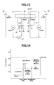
- diffusion limiting current Im is allowed to flow from measuring electrode 29 toward inner electrode 28, as shown by the arrow of Fig. 13.
- Ammeter detects and outputs this diffusion limiting current Im as a detected signal to determine lean air/fuel ratio using the characteristic line of Fig. 8.
- Nernst voltage Vnr (e.g., about 900mV) under rich air/fuel ratio condition is set, relative to working voltage Va (e.g., 450mV) of direct current power source 36 and working voltage (e.g., 1.6V) of direct current power source 39, in a manner to satisfy the following expression (7).
- Va e.g., 450mV
- 1.6V working voltage
- combined pumping voltage Upb of reference cell 32 is higher than pumping voltage Upa of measuring cell 30 in the case of rich air/fuel ratio, too. Therefore, the amount of oxygen absorbed by combined pumping voltage Upb into void spaces (oxygen receiving chambers) 43 of inner electrode 28 is set to be higher than that of oxygen absorbed by pumping voltage Upa out of void spaces 43 of inner electrode 28.
- oxygen partial pressure of void spaces 43 of inner electrode 28 is always kept higher than the external exhaust gas.
- lead 28A of inner electrode 28 also contain void spaces 43. With this, as shown in Fig. 1, the oxygen receiving chambers of void spaces 43 are in communication with the atmosphere in casing 1, thereby preventing a so-called reverse diffusion of the external exhaust gas toward void spaces 43.
- air/fuel ratio detecting device 21 As stated above, it is possible to produce air/fuel ratio detecting device 21 into a cylindrical shape in its entirety. Therefore, it is possible to provide electrodes 28, 29, 31 with sufficient electrode areas and to reduce internal resistance and size of air/fuel ratio detecting device 21, as compared with conventional air/fuel ratio detecting devices of platy shape.
- air/fuel ratio detecting devices have edge portions due to their platy shape.
- air/fuel ratio detecting device 21 of the present invention does not have such edge portions due to its cylindrical shape. Therefore, it is possible by air/fuel ratio detecting device 21 to reduce thermal stress and the like by about a half. This makes it possible to prevent, for example, cracks of solid electrolyte layer 27.
- heater portion 22 is fully covered with solid electrolyte layer 27, diffusion layer 34 and the like. With this, heater portion 22 is prevented from a direct contact with the outside air. Therefore, it is possible to efficiently transmit heat from heater portion to solid electrolyte layer 27 and the like.
- Air/fuel ratio detecting device 21 has a construction in which solid electrolyte layer 27 is interposed between inner electrode 28 and measuring electrode 29 and between inner electrode 28 and reference electrode 31. With this, it is possible to form measuring cell 30 and reference cell 32 (first and second pumping cells) by using only a single layer of solid electrolyte layer 27.
- a second embodiment of the present invention which is characterized in that the ceramic material of the inner electrode is made of an oxide having a perovskite structure (mixed conductive material).
- the same parts as those of the first embodiment are designated by the same numerals, and their explanations are omitted.
- inner electrode 50 is an inner electrode (first electrode) used in the second embodiment. Similar to the first embodiment, inner electrode 50 is formed of noble metal material (e.g., platinum) 51, ceramic grains 52 and void spaces 53.
- noble metal material e.g., platinum
- recesses 54 Similar to recesses 44 of the first embodiment, there are provided a plurality of recesses 54 on the boundary of inner electrode 50 and solid electrolyte 27.
- perovskite oxide constituting ceramic grains (mixed conductive material) 52, may have a structure of La 1-x Sr x CoO 3 or La 1-x Sr x MnO 3 .
- ceramic grains 52 serve to conduct oxygen ions (O 2- ) at the interface between ceramic grains 52 and solid electrolyte layer 27 and to generate the electrode reactions of the reaction formulas (1) and (2) at the interface between ceramic grains 52 and void spaces 53.
- Fig. 16 there also occurs the electrode reaction at three-phase interfaces F1, F2 formed among solid electrolyte layer 27, noble metal material 51 and void spaces 53 and at three-phase interfaces F3, F4 formed among solid electrolyte layer 27, noble metal material 51 and recesses 54.
- Void spaces 53 serve as oxygen receiving chambers, thereby diffusing oxygen in inner electrode 50 according to its concentration and pressure gradients.
- the oxygen concentration of the left side (leading end side of device 21) of inner electrode 50 in Fig. 16 is lower than that of the right side (base end side of device 21). Therefore, oxygen molecules and ions are transported in the direction of arrow "b" of Fig. 16 according to their concentration gradient.
- the second embodiment of the present invention can bring about advantageous effects similar to those of the first embodiment. Specifically, since ceramic grains 52 of inner electrode 50 are made of an oxide of perovskite structure in the second embodiment, it is possible to uniformly distribute many of the above-mentioned three-phase interfaces (electrode reaction points), thereby effectively generate the electrode reaction at the entirety of the electrode surface of inner electrode 50.
- void spaces 53 and ceramic grains 52 are continuously distributed in inner electrode 50. With this distribution, void spaces 53 contribute to oxygen transportation (in the form of oxygen molecules) by diffusion therein, and in contrast ceramic grains (mixed conductive material) 52 contribute to oxygen transportation (in the form of oxygen ions) by ionic conduction.
- oxygen ions (O 2- ) from solid electrolyte layer 27 can pass in the form of oxygen ions through the adjacent ceramic grain 52. Then, at the boundary between this ceramic grain 52 and the adjacent void space 53, oxygen ions can turn to oxygen molecules by the reaction of 2O 2- ⁇ O 2 + 4e. The resulting oxygen molecules can pass through this void space 53 by gas diffusion. Then, at the boundary between this void space 53 and the next ceramic grain 52, oxygen molecules can turn to oxygen ions by the reaction of O 2 + 4e ⁇ 2O 2- . In this manner, oxygen can be transported through ceramic grains 52 and void spaces 53 in the second oxygen gas transportation. Therefore, it is possible to accelerate the transportation speed of oxygen gas in the direction of the arrow of "b" in Fig. 16 by the above-mentioned first and second oxygen gas transportations.
Landscapes
- Chemical & Material Sciences (AREA)
- Life Sciences & Earth Sciences (AREA)
- Health & Medical Sciences (AREA)
- Physics & Mathematics (AREA)
- Chemical Kinetics & Catalysis (AREA)
- Electrochemistry (AREA)
- Molecular Biology (AREA)
- Analytical Chemistry (AREA)
- Biochemistry (AREA)
- General Health & Medical Sciences (AREA)
- General Physics & Mathematics (AREA)
- Immunology (AREA)
- Pathology (AREA)
- Measuring Oxygen Concentration In Cells (AREA)
Abstract
Description
Claims (10)
- An air/fuel ratio detection apparatus for a gas, comprising:a heater portion that has an elongate cylindrical shape and heats by applying electricity to the heater portion from an outside;a solid electrolyte layer formed on and entirely surrounding periphery of the heater portion, the solid electrolyte layer being activated by heat from the heater portion to conduct oxygen ions through the solid electrolyte layer;a first electrode that is positioned between the heater portion and the solid electrolyte layer and is in contact with an inner surface of the solid electrolyte layer;second and third electrodes that are in contact with an outer surface of the solid electrolyte layer and are away from each other such that the solid electrolyte layer is interposed between the first and second electrodes and between the first and third electrodes;a first voltage applying device for applying a first voltage between the first and second electrodes;a second voltage applying device for applying a second voltage between the first and third electrodes, the second voltage being higher than the first voltage; anda diffusion layer made of a porous material, the diffusion layer covering the second electrode to adjust transmission of the gas to the second electrode.
- An air/fuel ratio detection apparatus for a gas, comprising:wherein the first and second voltage applying devices are configured such that the first and second voltages are adjusted to allow an output signal from the second electrode to change according to air-fuel ratio of the gas.a heater portion that has an elongate cylindrical shape and heats by applying electricity to the heater portion from an outside;a solid electrolyte layer formed on and entirely surrounding periphery of the heater portion, the solid electrolyte layer being activated by heat from the heater portion to conduct oxygen ions through the solid electrolyte layer;a first electrode that is positioned between the heater portion and the solid electrolyte layer and is in contact with an inner surface of the solid electrolyte layer;second and third electrodes that are in contact with an outer surface of the solid electrolyte layer and are away from each other such that the solid electrolyte layer is interposed between the first and second electrodes and between the first and third electrodes;a first voltage applying device for applying a first voltage between the first and second electrodes; anda second voltage applying device for applying a second voltage between the first and third electrodes, the second voltage being higher than the first voltage,
- An apparatus according to claim 1 or 2, wherein the second electrode is positioned closer to a leading edge of the heater portion than the third electrode is.
- An apparatus according to claim 1 or 2, further comprising an ammeter provided between the first voltage applying device and the second electrode, for outputting the output signal as an electric current.
- An apparatus according to claim 1 or 2, wherein the second and third electrodes are positioned to be away from each other in an axial direction of the solid electrolyte layer, and
wherein the first electrode extends to have a length in the axial direction of the solid electrolyte layer such that the first electrode is opposed to the second and third electrodes in a radial direction of the solid electrolyte layer. - An apparatus according to claim 1 or 2, wherein the first electrode comprises a noble metal, ceramic grains, and voids that accommodate oxygen.
- An apparatus according to claim 6, wherein the voids have a size larger than that of the ceramic grains.
- An apparatus according to claim 6, wherein the ceramic grains comprise a ceramic raw material that is identical with a raw material of the solid electrolyte layer.
- An apparatus according to claim 6, wherein the ceramic grains comprise a ceramic raw material that is an oxide having a perovskite structure.
- An apparatus according to claim 1 or 2, wherein the heater portion comprises:a heater core made of a ceramic material and having a hollow cylindrical shape;a heater pattern formed on a peripheral surface of the heater core; andan insulating covering layer surrounding periphery of the heater core to cover the heater pattern.
Applications Claiming Priority (2)
| Application Number | Priority Date | Filing Date | Title |
|---|---|---|---|
| JP2002096102A JP3782031B2 (en) | 2002-03-29 | 2002-03-29 | Air-fuel ratio detection device |
| JP2002096102 | 2002-03-29 |
Publications (3)
| Publication Number | Publication Date |
|---|---|
| EP1348950A2 true EP1348950A2 (en) | 2003-10-01 |
| EP1348950A3 EP1348950A3 (en) | 2004-05-26 |
| EP1348950B1 EP1348950B1 (en) | 2007-12-05 |
Family
ID=27800558
Family Applications (1)
| Application Number | Title | Priority Date | Filing Date |
|---|---|---|---|
| EP03007029A Expired - Lifetime EP1348950B1 (en) | 2002-03-29 | 2003-03-27 | Air/fuel ratio detection apparatus |
Country Status (5)
| Country | Link |
|---|---|
| US (1) | US7122103B2 (en) |
| EP (1) | EP1348950B1 (en) |
| JP (1) | JP3782031B2 (en) |
| KR (1) | KR100474223B1 (en) |
| DE (1) | DE60317841T2 (en) |
Cited By (3)
| Publication number | Priority date | Publication date | Assignee | Title |
|---|---|---|---|---|
| WO2005036159A1 (en) * | 2003-10-09 | 2005-04-21 | Robert Bosch Gmbh | Sensor element for a probe |
| EP1555526A1 (en) * | 2004-01-19 | 2005-07-20 | Hitachi Ltd. | Oxygen sensor |
| EP1555525A1 (en) * | 2004-01-19 | 2005-07-20 | Hitachi Ltd. | Oxygen sensor and method of producing same |
Families Citing this family (16)
| Publication number | Priority date | Publication date | Assignee | Title |
|---|---|---|---|---|
| JP3966805B2 (en) * | 2002-11-18 | 2007-08-29 | 株式会社日立製作所 | Air-fuel ratio detection device |
| JP2004198362A (en) * | 2002-12-20 | 2004-07-15 | Denso Corp | Gas sensor |
| JP2005351737A (en) * | 2004-06-10 | 2005-12-22 | Hitachi Ltd | Oxygen concentration detection element |
| JP2005351741A (en) * | 2004-06-10 | 2005-12-22 | Hitachi Ltd | Oxygen concentration detection element |
| EP1605255A1 (en) * | 2004-06-10 | 2005-12-14 | Hitachi, Ltd. | Oxygen-concentration detecting element and method of producing same |
| US7270550B1 (en) * | 2006-07-11 | 2007-09-18 | Cheng Uei Precision Industry Co., Ltd. | Board to board connector |
| DE102006062060A1 (en) * | 2006-12-29 | 2008-07-03 | Robert Bosch Gmbh | Sensor e.g. lambda sensor, unit for determining oxygen concentration of exhaust gas of e.g. diesel engine vehicle, has electrodes arranged within unit, where one electrode is connected with reference gas chamber over exhaust channel |
| US20090050479A1 (en) * | 2007-08-23 | 2009-02-26 | Robert Bosch Gmbh | Exhaust gas sensor |
| US20090050480A1 (en) * | 2007-08-23 | 2009-02-26 | Robert Bosch Gmbh | Exhaust gas sensor |
| AT510702B1 (en) * | 2010-12-01 | 2012-06-15 | Avl List Gmbh | METHOD AND DEVICE FOR EVALUATING THE CONDITION OF A FUEL AIR MIXTURE |
| CN104981600B (en) | 2013-01-29 | 2017-08-25 | 丰田自动车株式会社 | The control device of internal combustion engine |
| WO2014118893A1 (en) * | 2013-01-29 | 2014-08-07 | トヨタ自動車株式会社 | Control device for internal combustion engine |
| JP6476607B2 (en) * | 2014-06-30 | 2019-03-06 | 株式会社デンソー | Gas sensor element |
| KR20180104070A (en) * | 2016-02-24 | 2018-09-19 | 다나카 기킨조쿠 고교 가부시키가이샤 | Metal paste for gas sensor electrode formation |
| US20190094173A1 (en) * | 2016-02-24 | 2019-03-28 | Tanaka Kikinzoku Kogyo K.K. | Gas Sensor Electrode and Method for Producing Same |
| DE102023117479A1 (en) * | 2022-07-20 | 2024-01-25 | Ngk Insulators, Ltd. | Gas sensor element and gas sensor |
Family Cites Families (10)
| Publication number | Priority date | Publication date | Assignee | Title |
|---|---|---|---|---|
| JPS59197851A (en) * | 1983-04-26 | 1984-11-09 | Ngk Insulators Ltd | Electrochemical element and apparatus |
| JPS6110762A (en) | 1984-06-26 | 1986-01-18 | Nissan Motor Co Ltd | Air/fuel ratio measuring apparatus |
| JPH0617891B2 (en) * | 1984-07-06 | 1994-03-09 | 日本電装株式会社 | Oxygen concentration detector |
| JPS6147553A (en) * | 1984-08-13 | 1986-03-08 | Hitachi Ltd | Air/fuel ratio sensor for automobile |
| JPS6151555A (en) * | 1984-08-21 | 1986-03-14 | Ngk Insulators Ltd | Electrochemical device |
| US4980042A (en) * | 1986-03-24 | 1990-12-25 | Ngk Spark Plug Co., Ltd. | Oxygen sensor and method of making it |
| US5360528A (en) * | 1992-07-20 | 1994-11-01 | General Motors Corporation | Wide range oxygen sensor |
| KR960024356A (en) * | 1994-12-26 | 1996-07-20 | 이형도 | Wide area air fuel ratio sensor and its driving method |
| DE4447033C2 (en) * | 1994-12-28 | 1998-04-30 | Bosch Gmbh Robert | Sensor for determining the oxygen content in gas mixtures |
| FR2744218B1 (en) * | 1996-01-31 | 2000-01-14 | Denso Corp | AIR-FUEL RATIO DETECTOR |
-
2002
- 2002-03-29 JP JP2002096102A patent/JP3782031B2/en not_active Expired - Lifetime
-
2003
- 2003-03-27 EP EP03007029A patent/EP1348950B1/en not_active Expired - Lifetime
- 2003-03-27 DE DE60317841T patent/DE60317841T2/en not_active Expired - Fee Related
- 2003-03-28 KR KR10-2003-0019365A patent/KR100474223B1/en not_active Expired - Fee Related
- 2003-03-31 US US10/401,560 patent/US7122103B2/en not_active Expired - Fee Related
Cited By (4)
| Publication number | Priority date | Publication date | Assignee | Title |
|---|---|---|---|---|
| WO2005036159A1 (en) * | 2003-10-09 | 2005-04-21 | Robert Bosch Gmbh | Sensor element for a probe |
| EP1555526A1 (en) * | 2004-01-19 | 2005-07-20 | Hitachi Ltd. | Oxygen sensor |
| EP1555525A1 (en) * | 2004-01-19 | 2005-07-20 | Hitachi Ltd. | Oxygen sensor and method of producing same |
| US7655122B2 (en) | 2004-01-19 | 2010-02-02 | Hitachi, Ltd. | Oxygen concentration detecting element |
Also Published As
| Publication number | Publication date |
|---|---|
| KR20030078729A (en) | 2003-10-08 |
| US20030188967A1 (en) | 2003-10-09 |
| EP1348950A3 (en) | 2004-05-26 |
| JP2003294695A (en) | 2003-10-15 |
| DE60317841D1 (en) | 2008-01-17 |
| JP3782031B2 (en) | 2006-06-07 |
| US7122103B2 (en) | 2006-10-17 |
| EP1348950B1 (en) | 2007-12-05 |
| KR100474223B1 (en) | 2005-03-09 |
| DE60317841T2 (en) | 2008-12-04 |
Similar Documents
| Publication | Publication Date | Title |
|---|---|---|
| EP1348950B1 (en) | Air/fuel ratio detection apparatus | |
| JP2885336B2 (en) | Method and apparatus for measuring NOx concentration in gas to be measured | |
| EP0259175B1 (en) | Electrochemical gas sensor, and method for manufacturing the same | |
| US4300991A (en) | Air-fuel ratio detecting apparatus | |
| US4861456A (en) | Electrochemical device | |
| JP3272215B2 (en) | NOx sensor and NOx measuring method | |
| US7045047B2 (en) | Gas sensor element | |
| US20030205078A1 (en) | Gas-detecting element and gas-detecting device comprising same | |
| EP0188900A2 (en) | Electrochemical device | |
| JPS6338154A (en) | Nox sensor | |
| GB2057140A (en) | Device for producing control signal for feed-back control of air/fuel mixing ratio | |
| US4302312A (en) | Device for producing control signal for feedback control of air/fuel mixing ratio | |
| EP0798556B1 (en) | Gas sensor | |
| US7258772B2 (en) | Oxygen sensor and method of manufacturing same | |
| US6338782B1 (en) | Gas sensor | |
| JPH11326268A (en) | Flat limit current sensor | |
| JP3966805B2 (en) | Air-fuel ratio detection device | |
| US7258771B2 (en) | Air/fuel ratio detection apparatus | |
| JP2004226171A (en) | Oxygen concentration detector | |
| US6270639B1 (en) | Electrochemical sensor | |
| JP3511468B2 (en) | Measuring method of NOx concentration in measured gas | |
| JP2003121412A (en) | Gas sensor solid electrolyte based sensor element for measuring gas components in gas mixtures | |
| JP2005121666A (en) | Nox sensor | |
| JP4015569B2 (en) | Air-fuel ratio detection device | |
| JP3571039B2 (en) | Measurement device for NOx concentration in gas to be measured |
Legal Events
| Date | Code | Title | Description |
|---|---|---|---|
| PUAI | Public reference made under article 153(3) epc to a published international application that has entered the european phase |
Free format text: ORIGINAL CODE: 0009012 |
|
| 17P | Request for examination filed |
Effective date: 20030327 |
|
| AK | Designated contracting states |
Kind code of ref document: A2 Designated state(s): AT BE BG CH CY CZ DE DK EE ES FI FR GB GR HU IE IT LI LU MC NL PT RO SE SI SK TR |
|
| AX | Request for extension of the european patent |
Extension state: AL LT LV MK |
|
| PUAL | Search report despatched |
Free format text: ORIGINAL CODE: 0009013 |
|
| AK | Designated contracting states |
Kind code of ref document: A3 Designated state(s): AT BE BG CH CY CZ DE DK EE ES FI FR GB GR HU IE IT LI LU MC NL PT RO SE SI SK TR |
|
| AX | Request for extension of the european patent |
Extension state: AL LT LV MK |
|
| RIC1 | Information provided on ipc code assigned before grant |
Ipc: 7G 01N 27/407 B Ipc: 7G 01N 27/406 A |
|
| AKX | Designation fees paid |
Designated state(s): DE FR GB |
|
| RAP1 | Party data changed (applicant data changed or rights of an application transferred) |
Owner name: HITACHI, LTD. |
|
| GRAP | Despatch of communication of intention to grant a patent |
Free format text: ORIGINAL CODE: EPIDOSNIGR1 |
|
| GRAS | Grant fee paid |
Free format text: ORIGINAL CODE: EPIDOSNIGR3 |
|
| GRAA | (expected) grant |
Free format text: ORIGINAL CODE: 0009210 |
|
| AK | Designated contracting states |
Kind code of ref document: B1 Designated state(s): DE FR GB |
|
| REG | Reference to a national code |
Ref country code: GB Ref legal event code: FG4D |
|
| REF | Corresponds to: |
Ref document number: 60317841 Country of ref document: DE Date of ref document: 20080117 Kind code of ref document: P |
|
| PGFP | Annual fee paid to national office [announced via postgrant information from national office to epo] |
Ref country code: GB Payment date: 20080318 Year of fee payment: 6 |
|
| PGFP | Annual fee paid to national office [announced via postgrant information from national office to epo] |
Ref country code: DE Payment date: 20080326 Year of fee payment: 6 |
|
| EN | Fr: translation not filed | ||
| PLBE | No opposition filed within time limit |
Free format text: ORIGINAL CODE: 0009261 |
|
| STAA | Information on the status of an ep patent application or granted ep patent |
Free format text: STATUS: NO OPPOSITION FILED WITHIN TIME LIMIT |
|
| 26N | No opposition filed |
Effective date: 20080908 |
|
| PG25 | Lapsed in a contracting state [announced via postgrant information from national office to epo] |
Ref country code: FR Free format text: LAPSE BECAUSE OF FAILURE TO SUBMIT A TRANSLATION OF THE DESCRIPTION OR TO PAY THE FEE WITHIN THE PRESCRIBED TIME-LIMIT Effective date: 20081003 |
|
| GBPC | Gb: european patent ceased through non-payment of renewal fee |
Effective date: 20090327 |
|
| PG25 | Lapsed in a contracting state [announced via postgrant information from national office to epo] |
Ref country code: DE Free format text: LAPSE BECAUSE OF NON-PAYMENT OF DUE FEES Effective date: 20091001 |
|
| PG25 | Lapsed in a contracting state [announced via postgrant information from national office to epo] |
Ref country code: GB Free format text: LAPSE BECAUSE OF NON-PAYMENT OF DUE FEES Effective date: 20090327 |