EP1348877B1 - Torque resistant grommet - Google Patents
Torque resistant grommet Download PDFInfo
- Publication number
- EP1348877B1 EP1348877B1 EP03003362A EP03003362A EP1348877B1 EP 1348877 B1 EP1348877 B1 EP 1348877B1 EP 03003362 A EP03003362 A EP 03003362A EP 03003362 A EP03003362 A EP 03003362A EP 1348877 B1 EP1348877 B1 EP 1348877B1
- Authority
- EP
- European Patent Office
- Prior art keywords
- sleeve
- grommet
- aperture
- fastener
- shank
- Prior art date
- Legal status (The legal status is an assumption and is not a legal conclusion. Google has not performed a legal analysis and makes no representation as to the accuracy of the status listed.)
- Expired - Lifetime
Links
Images
Classifications
-
- B—PERFORMING OPERATIONS; TRANSPORTING
- B60—VEHICLES IN GENERAL
- B60R—VEHICLES, VEHICLE FITTINGS, OR VEHICLE PARTS, NOT OTHERWISE PROVIDED FOR
- B60R16/00—Electric or fluid circuits specially adapted for vehicles and not otherwise provided for; Arrangement of elements of electric or fluid circuits specially adapted for vehicles and not otherwise provided for
- B60R16/02—Electric or fluid circuits specially adapted for vehicles and not otherwise provided for; Arrangement of elements of electric or fluid circuits specially adapted for vehicles and not otherwise provided for electric constitutive elements
- B60R16/0207—Wire harnesses
- B60R16/0215—Protecting, fastening and routing means therefor
- B60R16/0222—Grommets
-
- F—MECHANICAL ENGINEERING; LIGHTING; HEATING; WEAPONS; BLASTING
- F16—ENGINEERING ELEMENTS AND UNITS; GENERAL MEASURES FOR PRODUCING AND MAINTAINING EFFECTIVE FUNCTIONING OF MACHINES OR INSTALLATIONS; THERMAL INSULATION IN GENERAL
- F16B—DEVICES FOR FASTENING OR SECURING CONSTRUCTIONAL ELEMENTS OR MACHINE PARTS TOGETHER, e.g. NAILS, BOLTS, CIRCLIPS, CLAMPS, CLIPS OR WEDGES; JOINTS OR JOINTING
- F16B13/00—Dowels or other devices fastened in walls or the like by inserting them in holes made therein for that purpose
- F16B13/12—Separate metal or non-separate or non-metal dowel sleeves fastened by inserting the screw, nail or the like
- F16B13/124—Separate metal or non-separate or non-metal dowel sleeves fastened by inserting the screw, nail or the like fastened by inserting a threaded element, e.g. screw or bolt
-
- F—MECHANICAL ENGINEERING; LIGHTING; HEATING; WEAPONS; BLASTING
- F16—ENGINEERING ELEMENTS AND UNITS; GENERAL MEASURES FOR PRODUCING AND MAINTAINING EFFECTIVE FUNCTIONING OF MACHINES OR INSTALLATIONS; THERMAL INSULATION IN GENERAL
- F16B—DEVICES FOR FASTENING OR SECURING CONSTRUCTIONAL ELEMENTS OR MACHINE PARTS TOGETHER, e.g. NAILS, BOLTS, CIRCLIPS, CLAMPS, CLIPS OR WEDGES; JOINTS OR JOINTING
- F16B31/00—Screwed connections specially modified in view of tensile load; Break-bolts
- F16B31/02—Screwed connections specially modified in view of tensile load; Break-bolts for indicating the attainment of a particular tensile load or limiting tensile load
-
- F—MECHANICAL ENGINEERING; LIGHTING; HEATING; WEAPONS; BLASTING
- F16—ENGINEERING ELEMENTS AND UNITS; GENERAL MEASURES FOR PRODUCING AND MAINTAINING EFFECTIVE FUNCTIONING OF MACHINES OR INSTALLATIONS; THERMAL INSULATION IN GENERAL
- F16B—DEVICES FOR FASTENING OR SECURING CONSTRUCTIONAL ELEMENTS OR MACHINE PARTS TOGETHER, e.g. NAILS, BOLTS, CIRCLIPS, CLAMPS, CLIPS OR WEDGES; JOINTS OR JOINTING
- F16B13/00—Dowels or other devices fastened in walls or the like by inserting them in holes made therein for that purpose
- F16B13/001—Dowels or other devices fastened in walls or the like by inserting them in holes made therein for that purpose with means for preventing rotation of the dowel
-
- F—MECHANICAL ENGINEERING; LIGHTING; HEATING; WEAPONS; BLASTING
- F16—ENGINEERING ELEMENTS AND UNITS; GENERAL MEASURES FOR PRODUCING AND MAINTAINING EFFECTIVE FUNCTIONING OF MACHINES OR INSTALLATIONS; THERMAL INSULATION IN GENERAL
- F16B—DEVICES FOR FASTENING OR SECURING CONSTRUCTIONAL ELEMENTS OR MACHINE PARTS TOGETHER, e.g. NAILS, BOLTS, CIRCLIPS, CLAMPS, CLIPS OR WEDGES; JOINTS OR JOINTING
- F16B37/00—Nuts or like thread-engaging members
- F16B2037/007—Nuts or like thread-engaging members with a blind hole
-
- F—MECHANICAL ENGINEERING; LIGHTING; HEATING; WEAPONS; BLASTING
- F16—ENGINEERING ELEMENTS AND UNITS; GENERAL MEASURES FOR PRODUCING AND MAINTAINING EFFECTIVE FUNCTIONING OF MACHINES OR INSTALLATIONS; THERMAL INSULATION IN GENERAL
- F16B—DEVICES FOR FASTENING OR SECURING CONSTRUCTIONAL ELEMENTS OR MACHINE PARTS TOGETHER, e.g. NAILS, BOLTS, CIRCLIPS, CLAMPS, CLIPS OR WEDGES; JOINTS OR JOINTING
- F16B37/00—Nuts or like thread-engaging members
- F16B37/005—Nuts or like thread-engaging members into which threads are cut during screwing
-
- F—MECHANICAL ENGINEERING; LIGHTING; HEATING; WEAPONS; BLASTING
- F16—ENGINEERING ELEMENTS AND UNITS; GENERAL MEASURES FOR PRODUCING AND MAINTAINING EFFECTIVE FUNCTIONING OF MACHINES OR INSTALLATIONS; THERMAL INSULATION IN GENERAL
- F16B—DEVICES FOR FASTENING OR SECURING CONSTRUCTIONAL ELEMENTS OR MACHINE PARTS TOGETHER, e.g. NAILS, BOLTS, CIRCLIPS, CLAMPS, CLIPS OR WEDGES; JOINTS OR JOINTING
- F16B5/00—Joining sheets or plates, e.g. panels, to one another or to strips or bars parallel to them
- F16B5/02—Joining sheets or plates, e.g. panels, to one another or to strips or bars parallel to them by means of fastening members using screw-thread
- F16B5/0258—Joining sheets or plates, e.g. panels, to one another or to strips or bars parallel to them by means of fastening members using screw-thread using resiliently deformable sleeves, grommets or inserts
Definitions
- the present invention relates to a torque resistant grommet that permits the use of relatively high torque settings in driving fasteners thereinto.
- US 3 841 177 relates to a torque limiting gripping device for a bolt head or a bolt nut comprising a grip element threaded on the bolt head or nut.
- the free end of the bolt nut is provided with an abutment against which the grip element is screwed to produce pre-stressed engagement.
- the bolt or nut is tightened and the grip element begins to rotate on the head or nut when the pre-stress torque is exceeded.
- US 6 244 805 B1 relates to a grommet with elastomeric and relatively rigid portions.
- a torque resistant grommet that may be pre-assembled with a primary panel of a structure such as an automobile frame, that is resistant to spinning within an aperture into which it is received so as to allow a threaded fastener to be driven thereinto, and which is furthermore resistant to the stripping of interior of the grommet.
- a grommet constructed according to the principles of the present invention has a shank and a head that extends laterally therefrom.
- the shank is constructed and arranged for retained insertion in an aperture formed in a structure and the head of the grommet acts to limit the insertion of the shank into the aperture.
- the shank itself is made up of an inner sleeve and an outer sleeve.
- the outer sleeve forms the exterior of the shank and the interior sleeve is disposed within the outer sleeve.
- the inner sleeve has a bore formed therein that is constructed and arranged to threadedly receive a threaded fastener.
- the inner sleeve is secured within the outer sleeve such that a predetermined torque level, referred to as a release torque, will cause the inner sleeve spin within the outer sleeve.
- This spinning action limits the amount of torque that a threaded fastener may exert on the inner sleeve of the grommet.
- the release torque is preferably set below the level of torque at which a threaded fastener will strip out threads formed in the bore of the inner sleeve, the spinning inner sleeve prevents stripping of the grommet.
- the shank preferably has a cross-sectional shape that is complementary to the shape of the aperture of the structure into which the grommet is inserted. What is more, the shank of the grommet will be constructed and arranged to resist spinning within the aperture.
- Another feature of the present invention is the inclusion of at least one retaining structure on the shank of the grommet.
- This retaining structure acts to retain the shank of the grommet within the aperture so that the grommet may be pre-assembled with the structure into which the aperture is formed.
- the retaining structure may take many forms, among which are included a flexible vane, a flexible finger, a ramped projection, an outwardly extending ridge, and a plurality of annular projections.
- a laterally projecting collar that extends from a bottom end of the inner sleeve.
- the collar is retained within a complementarily shaped channel formed on the interior surface of the outer sleeve. In this way, the inner sleeve may rotate within the outer sleeve without being pulled therefrom.
- the release torque may be set in many different manners, including, but not limited to adhering the outer sleeve to the inner sleeve, mechanically or thermoplastically securing the outer sleeve to the inner sleeve, and forming on the exterior of the inner sleeve and/or on the interior of the exterior sleeve at least one projection that contacts the other sleeve in such a manner as to prevent relative rotation therebetween.
- the outer surface of the inner sleeve has formed therein a plurality of projections that have a lower release torque in a clockwise direction and a higher release torque in a counter-clockwise direction. Alternatively, the higher and lower torque directions may be reversed.
- the inner sleeve of the grommet In order to prevent a threaded fastener from stripping the inner sleeve of the grommet and thereby damaging it, it is preferred to form the inner sleeve of a relatively hard material. And, as the outer sleeve has more need to deform, the outer sleeve will typically be fashioned of a relatively softer material.
- the grommet may be formed using an over-molding process or a two-shot injection process. Alternatively, the inner sleeve and outer sleeve are formed independent of one another and subsequently assembled.
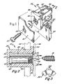
- FIG. 1 is a schematic perspective view of a torque resistant grommet of the present invention in use
- FIG. 2 is a partial cross-section of the torque resistant grommet of FIG. 1 shown inserted into an aperture in a primary panel;
- FIG. 3 is a partial cross-sectional view of an interior sleeve of the torque resistant grommet of the present invention.
- FIG. 1 illustrates a torque resistant grommet 10 of the present invention.
- Grommet 10 is received into an aperture 12 formed through a primary panel 14.
- a secondary panel 16 may be secured to the primary panel 14 by means of a threaded fastener 18 that is passed through a bore 20 formed through the panel 16 and into a bore 22 formed into the grommet 10.
- FIG. 2 shows a partial cross-section of the grommet 10.
- the grommet 10 is comprised of an inner sleeve 26 that is surrounded by and received within an outer sleeve 28. It is to be noted that the inner and outer sleeve 26, 28 are distinct structures and not merely different areas of the same object. Together, the inner and outer sleeves 26, 28 form the body of the grommet 10.
- the grommet 10 has a shank 30 with a top end 32 and a distal end 34. A head 36 extends laterally from the top end 32 of the shank 30. When the shank 30 of the grommet 10 is inserted into an aperture 12, the head 36 of the grommet acts to prevent the grommet from passing entirely through the aperture 12.
- the shank 30 of the grommet 10 typically has at least one retaining mechanism 38 extending therefrom that permits the grommet 10 to be pre-assembled with a primary panel 14.
- the retaining structures 38 may be of any useful form, but in this preferred embodiment comprise a flexible vane 39 that extends laterally from the shank 30.
- the retaining mechanism 38 in this case the flexible vane 39, will engage the side of the primary panel opposite the head 36 and prevent the extraction of the grommet 10 from the aperture 12.
- the retaining mechanism 38 may also be a flexible finger, a ramped projection, an outwardly extending ridge, or a plurality of annular projections.
- the retaining structure(s) 38 provide the entire means whereby the grommet 10 is retained in the aperture 12.
- the grommet 10 may be constructed and arranged so that its shank 30 expands as a fastener 18 is driven thereinto, thereby preventing the grommet 10 from being extracted from an aperture 10.
- the inner sleeve 26 of the grommet 10 defines the bore 22 into which threaded fastener 18 is received. As can be seen, the bore 22 is accessible through the head 36 formed into the outer sleeve 28. The bore 22 may pass entirely through the inner sleeve 26 or may be a blind bore extending only part way into the inner sleeve 26. The bore 22 will have a diameter somewhat smaller than the fastener 18 that is intended to be driven therein and it is preferred that the bore 22 have longitudinal grooves formed therein that allow for deformed material to be displaced as a fastener 18 is driven into the bore 22.
- the bore 22 may be smooth, have threads, or other types of projections formed therein that facilitate the retention of a fastener therein.
- the inner sleeve 26 is preferably fashioned of a material softer than the threaded fastener 28 such that the threaded fastener 18 may cut threads into the interior surface of the bore 22. Where the inner sleeve 26 is made of a material that is harder than the threaded fastener 18, the inner sleeve 26 will be provided with interior threads that mate with the threads of the fastener 18.
- the inner sleeve 16 is threaded insert made of brass, aluminum, steel or the like that is over molded with the exterior sleeve 28.
- the outer sleeve 28 of the grommet 10 is formed of a relatively soft and elastic material. Not only can this material deform so as to adapt to the contours of the aperture 12 and to grip those contours, but as the retaining mechanisms 38 are preferably formed integral to the outer sleeve 28 and from the same material, the retaining mechanisms 38 will be able to resiliently deform as they are inserted into the aperture 12 and yet snap back to perform their retaining function. This softer material also lowers the amount of force needed to insert the grommet 10 into the aperture 12.
- the inner sleeve 26, on the other hand, must be sufficiently strong to resist the stripping of the bore 24 of the grommet 10.
- the exterior sleeve 28 will be formed of a material that is relatively softer than the material from which the inner sleeve 26 is formed. It must be remembered, however, that the inner and outer sleeves 26, 28 of the grommet 10 may be formed of the same materials and also that, where so needed, the inner sleeve 26 may be formed of a material that is softer than the exterior sleeve 28.
- the interior sleeve 26 is made of glass or ceramic filled polyamide such as nylon or an acetal material and the outer sleeve 28 is made of nylon.
- the fastener 18 will impart a torque to the inner sleeve 26 about the axis of rotation of the fastener 18.
- the shank 30 of the grommet 10 will be of a non-circular form such that the geometry of the shank 10 and that of the complementary aperture 12 will prevent rotation of the grommet 10 within the aperture 12. While the preferred embodiment of the grommet 10 comprises a substantially square shank 30, it is contemplated that the shank 30 may be formed into virtually any shape, including even a circular shape. But where a circular shank 30 is used, care must be taken to ensure that the torque resistant properties of the grommet 10 of the present invention will account for the increased tendency of the circular grommet 10 to spin within the aperture 12.
- the inner sleeve 26 is secured within the outer sleeve 28 in such a manner as to resist the torque forces applied thereto by the fastener 18. However, where the torque applied to the inner sleeve 26 by the fastener 18 exceeds a predetermined threshold level referred to as the release torque, the inner sleeve 26 will begin to rotate within the outer sleeve 28 to the extent necessary to relieve the torque forces applied to the inner sleeve 26 that exceed the predetermined release torque levels.
- the release torque levels are set so as to be higher than the torque level required to securely clamp the secondary panel 16 to the primary panel 14 under the influence of the fastener 18 but below the torque level at which the bore 22 will be stripped by the fastener 18.
- an outwardly extending flange 40 into the exterior of the inner sleeve 26.
- This outwardly extending flange is preferably located away from the head 36 of the grommet 10 within the shank 30 thereof.
- the flange 40 is received within a complementary groove or channel 42 formed on the interior of the outer sleeve 28. The interlocking action of the flange 40 and channel 42 prevent the inner sleeve 26 from being extracted from the exterior sleeve 28 of the grommet 10 even after the release torque has been exceeded.
- the magnitude of the release torque is dictated by the hold that the outer sleeve 28 has on the inner sleeve 26.
- This hold or grasp may be created by the use of adhesives between the inner and outer sleeves 26, 28, by forming mechanical torque resisting structures therebetween, or even by mechanically or thermoplastically deforming the inner and outer sleeves 26, 28 to prevent the rotation of the inner sleeve 26 within the outer sleeve 28.
- rotation of the inner sleeve 26 within the outer sleeve 28 is prevented by a series of longitudinal grooves 44 formed into the exterior of the inner sleeve 26. These grooves 44 engage grooves or projections (not shown) that are formed on the interior surface of the exterior sleeve 28.
- these grooves 44 may be formed to resist rotation of the inner sleeve 26 to a greater degree in one rotation direction than in the other.
- the grooves 44 illustrated in FIG. 3 are of a saw-tooth shape that is inclined to the left, a fastener 18 that is drive into the bore 22 of the inner sleeve 26 in the typical clockwise rotation, will experience a lower release torque than if the same fastener 18 were rotated in a counter-clockwise direction.
- the structure of the grooves 44 illustrated in FIG. 3 is such that a fastener 18 may be backed out of the bore 22 even after the release torque has been exceeded.
- the release torque may be advantageously specified at a level that permits a desired clamping force to be exerted upon a secondary panel or other structure 16 that is to be secured to the primary panel 14 by the fastener 18.
- a driving tool such as a hand-held drill may be used at virtually any torque setting to rapidly drive a fastener 18 into the grommet 10 without fear of stripping the bore 22 formed into the grommet 10.
- the inner sleeve 26 may be constrained not to rotate, or may be fashioned so as to have a very high release torque.
- the low insertion force requirement engendered by the relatively soft outer sleeve 28 combined with the strip resistant harder inner sleeve 26 yield a useful result even where the inner sleeve 26 is not free to rotate within the outer sleeve 28.
- the grommet 10 of the present invention has been described in conjunction with the attachment of a secondary panel or other structure 16 to a primary panel 14 of an automobile frame or the like, it is to be understood that the grommet 10 of the present invention may be adapted for use in many manufacturing settings. Accordingly, the present invention is not to be so limited. Furthermore, the grommet 10 of the present invention may be used as illustrated in the figures or may be formed as part of a larger, extended structure.
Landscapes
- Engineering & Computer Science (AREA)
- General Engineering & Computer Science (AREA)
- Mechanical Engineering (AREA)
- Dowels (AREA)
- Insulating Bodies (AREA)
- Installation Of Indoor Wiring (AREA)
Description
Claims (28)
- A grommet comprising:an outer sleeve (28) having a shank (30) and a head (36), the head (36) extending laterally from an end of the shank (30), the shank (30) being constructed and arranged for retained insertion in an aperture (12) formed in a structure (14), the head (36) acting to limit the insertion of the shank (30) into the aperture (12); andan inner sleeve (26) disposed within the shank (30) of the outer sleeve (28) and having a bore (22) formed therein that is constructed and arranged to receive a threaded fastener (18), the inner sleeve (26) being secured within the outer sleeve (28).
- A grommet according to claim 1, the inner sleeve (26) being releasably secured within the outer sleeve (28) such that a release torque at which the inner sleeve (26) is caused to rotate within the outer sleeve (28) is lower than a strip torque at which a threaded fastener may be caused to spin freely within the inner sleeve (26).
- The grommet of claim 1 or 2 wherein said shank (30) has a cross-sectional shape that is complementary to the aperture (12) of the structure (14) into which the grommet (10) is inserted, the shank (30) of the grommet (10) being constructed and arranged to resist spinning within the aperture (12).
- The grommet of at least one of claims 1 to 3 wherein the shank (30) further includes at least one retaining structure (38) extending from the outer surface of the shank (30) for retaining the grommet (10) within the aperture (12) in the structure (14).
- The grommet of claim 4 wherein said retaining structure (38) comprises one of a group consisting of a vane (39), a flexible finger, a ramped projection, an outwardly extending ridge, and a plurality of annular projections.
- The grommet of at least one of the preceding claims wherein the inner sleeve (26) has a laterally projecting collar (40) extending from a bottom end thereof, said collar (40) being retained within a complementarily shaped channel (42) in the outer sleeve (28), such that the inner sleeve (26) is positively retained within the outer shell.
- The grommet of at least one of the preceding claims wherein the inner sleeve (26) is fashioned of a relatively harder material and the outer sleeve (28) is fashioned of a relatively softer material.
- The grommet of at least one of the preceding claims wherein the inner sleeve (26) is adhered to the outer sleeve (28) to prevent relative rotation therebetween.
- The grommet of at least one of the preceding claims wherein the inner sleeve (26) is mechanically secured to the outer sleeve (28) so as to prevent relative rotation therebetween.
- The grommet of at least one of the preceding claims wherein the exterior surface of the inner sleeve (26) has formed therein at least one projection that contacts the outer sleeve (28) in such a manner as to prevent relative rotation therebetween.
- The grommet of at least one of the preceding claims wherein the inner sleeve (26) is formed prior to the outer sleeve (28), and the outer sleeve (28) is subsequently over-molded around the inner sleeve (26).
- The grommet of at least one of claims 1 to 10 wherein the inner sleeve (26) is formed within the outer sleeve (28) subsequent to the molding of the outer sleeve (28).
- The grommet of at least one of claims 1 to 10 wherein the inner sleeve (26) and outer sleeve (28) are formed independent of one another and subsequently assembled.
- The grommet of at least one of the preceding claims wherein the outer surface of the inner sleeve (26) has formed therein a plurality of projections having a lower release torque in a clockwise direction and a higher release torque in a counter-clockwise direction.
- The grommet of at least one of claims 1 to 13 wherein the outer surface of the inner sleeve (26) has formed therein a plurality of projections having a lower release torque in a counter-clockwise direction and a higher release torque in a clockwise direction.
- A torque limiting grommet according to claim 1 wherein
said inner sleeve (26) is an elongate fastener sleeve having a top end and a bottom end, the elongate fastener sleeve (26) having said bore (22) formed therein from the top end thereof that is constructed and arranged to receive said threaded fastener (18);
said outer sleeve (28) is an outer aperture sleeve formed around the fastener sleeve (26), the exterior of the aperture sleeve (28) being constructed and arranged to be received in said aperture (12) in said structure (14), the aperture sleeve (28) further comprising at least one retaining mechanism (38) that is constructed and arranged to retain the aperture sleeve (28) within the aperture (12);
said head (36) extends laterally from the outer aperture sleeve (28) and limits the depth to which the outer aperture sleeve (28) may be inserted into the aperture (12); and,
wherein the fastener sleeve (26) is secured within the aperture sleeve (28) such that a torque applied to the fastener sleeve (26) by the threaded fastener (18) will cause the fastener sleeve (26) to spin within the aperture sleeve (28) without becoming dislodged therefrom. - The torque limiting grommet of claim 16 wherein the fastener sleeve (26) further comprises a flange extending laterally from the bottom end thereof, the flange being received in a complementary channel formed in the interior of the aperture sleeve (28), the flange of the fastener sleeve (26) securely retaining the fastener sleeve (26) within the aperture sleeve (28).
- The torque limiting grommet of claim 16 or 17 wherein the outer surface of the fastener sleeve(26) has formed therein at least one projection that contacts the inner surface of the aperture sleeve (28) in such a way as to prevent rotation of the fastener sleeve (26) within the aperture sleeve (28) below a predetermined release torque threshold.
- The torque resistant grommet of at least one of claims 16 to 18 wherein said retaining structure (38) comprises one of a group consisting of a vane, a flexible finger, a ramped projection, an outwardly extending ridge, and a plurality of annular projections.
- The torque resistant grommet of at least one of claims 16 to 19 wherein the fastener sleeve(26) is formed of a material that is relatively harder and the aperture sleeve (28) formed of a material that is relatively softer.
- A torque limiting grommet according to claim 1 wherein
said inner sleeve (26) is an elongate fastener sleeve having a top end and a bottom end, the elongate fastener sleeve having said bore (22) formed therein from the top end (32) thereof that is constructed and arranged to receive a threaded fastener (18), the fastener sleeve also having said flange extending laterally from the bottom end thereof;
said outer sleeve (28) is an outer aperture sleeve formed around the fastener sleeve, the exterior of the aperture sleeve being constructed and arranged to be received in said aperture (12) in said structure (14), the aperture sleeve further comprising at least one retaining mechanism (38) that is constructed and arranged to retain the aperture sleeve (28) within the aperture (12), the aperture sleeve (28) having formed on an interior surface a channel that is complementary with the flange of the fastener sleeve (26), the flange of the apertures sleeve (28) being received in the complementary channel of the fastener sleeve (26) so as to securely retaining the fastener sleeve (26) within the aperture sleeve (28);
at least one projection extends from the exterior surface of the fastener sleeve (26) and contacts the inner surface of the aperture sleeve (28) in such a way as to prevent rotation of the fastener sleeve (26) within the aperture sleeve (28) below a predetermined release torque threshold;
the fastener sleeve (26) is formed of a material that is relatively harder and the aperture sleeve (28) is formed of a material that is relatively softer; and,
said head (36) extends laterally from the outer aperture sleeve and limits the depth to which the outer aperture sleeve (28) may be inserted into the aperture (12). - The grommet according to at least one of the preceding claims wherein said bore (22) in the inner sleeve (26) is constructed and arranged to threadedly receive said threaded fastener (18).
- A torque resistant grommet comprising:a shank (30) having a center core encapsulated within an outer layer, the shank (30) having a distal end (34) and an upper end (32), the upper end (32) of the shank (30) having a head (36) extending laterally therefrom, the grommet (10) having an aperture (22) formed longitudinally through the head and the core of the shank (30) sized so as to receive therein a fastener (18), the core of the shank (30) and the outer layer of the shank (30) being connected to one another in such a way as to exhibit a failure in the connection therebetween at a predetermined torque level.
- The torque resistant grommet of claim 23 wherein the shank (30) has a cross-sectional shape that is complementary to an aperture (12) in a structure (14) into which the grommet (10) is inserted, the shank (30) of the grommet (10) being constructed and arranged to resist spinning within the aperture (12).
- The torque resistant grommet of claim 23 or 24 wherein the shank (30) further includes at least one retaining structure (38) extending from the outer surface of the shank (30) for retaining the grommet (10) within the aperture (12) in the structure (14).
- The torque resistant grommet of claim 25 wherein said retaining structure (38) comprises one of a group consisting of a vane, a flexible finger, a ramped projection, an outwardly extending ridge, and a plurality of annular projections.
- The torque resistant grommet of at least one of claims 23 to 26 wherein the aperture (12) formed in the structure (14) is non-circular and the shank (30) of the grommet (10) is formed to fit therein in a complementary manner.
- The torque resistant grommet of at least one of claims 23 to 27 wherein a threaded fastener received within the center core of the shank (30) causes at least some portion of the shank (30) to expand, thereby securing the grommet (10) within the aperture (12) formed in the structure (14).
Applications Claiming Priority (2)
| Application Number | Priority Date | Filing Date | Title |
|---|---|---|---|
| US10/109,787 US6659698B2 (en) | 2002-03-28 | 2002-03-28 | Torque resistant grommet |
| US109787 | 2002-03-28 |
Publications (2)
| Publication Number | Publication Date |
|---|---|
| EP1348877A1 EP1348877A1 (en) | 2003-10-01 |
| EP1348877B1 true EP1348877B1 (en) | 2005-11-09 |
Family
ID=27804413
Family Applications (1)
| Application Number | Title | Priority Date | Filing Date |
|---|---|---|---|
| EP03003362A Expired - Lifetime EP1348877B1 (en) | 2002-03-28 | 2003-02-14 | Torque resistant grommet |
Country Status (5)
| Country | Link |
|---|---|
| US (1) | US6659698B2 (en) |
| EP (1) | EP1348877B1 (en) |
| CA (1) | CA2421356C (en) |
| DE (1) | DE60302170T2 (en) |
| ES (1) | ES2252560T3 (en) |
Families Citing this family (8)
| Publication number | Priority date | Publication date | Assignee | Title |
|---|---|---|---|---|
| CA2640558A1 (en) * | 2005-02-25 | 2006-08-31 | Kuna Group Ab | Fastener for a faucet |
| USD583650S1 (en) * | 2005-06-30 | 2008-12-30 | Illinois Tool Works Inc. | Grommet |
| CN100523525C (en) * | 2006-08-03 | 2009-08-05 | 川湖科技股份有限公司 | Quick nail sleeve fixing device |
| US20100207001A1 (en) * | 2009-02-13 | 2010-08-19 | Newfrey Llc | Conductive And Isolated 2-Shot Tube Clamp |
| US8752641B2 (en) | 2010-11-30 | 2014-06-17 | United Technologies Corporation | Torque protection device for fire blanket and associated method |
| US20170023045A1 (en) | 2015-07-20 | 2017-01-26 | Channell Commercial Corporation | Fastening system allowing component removal after fastener system failure |
| US11009058B2 (en) * | 2017-10-13 | 2021-05-18 | Illinois Tool Works Inc. | Anchoring part and apparatus for connecting two parts |
| US12444803B2 (en) * | 2021-03-19 | 2025-10-14 | Dana Automotive Systems Group, Llc | Battery enclosure fastener |
Family Cites Families (27)
| Publication number | Priority date | Publication date | Assignee | Title |
|---|---|---|---|---|
| US3425314A (en) * | 1967-08-09 | 1969-02-04 | John F Ohlson | Spring beam load limiting nut |
| DE1625306B1 (en) * | 1967-10-24 | 1971-02-25 | Daimler Benz Ag | SOCKET NUT FOR A SCREW CONNECTION |
| SE365589B (en) | 1972-08-21 | 1974-03-25 | P Waetterbaeck | |
| US3893365A (en) | 1973-12-28 | 1975-07-08 | Illinois Tool Works | Plastic screw grommet |
| US4026187A (en) | 1975-12-05 | 1977-05-31 | Illinois Tool Works Inc. | Plastic screw grommet |
| FR2375480A1 (en) | 1976-12-21 | 1978-07-21 | Comet | IMPROVEMENTS TO FIXING DEVICES |
| US4082030A (en) | 1977-03-25 | 1978-04-04 | Illinois Tool Works, Inc. | Plastic screw grommet |
| US4136599A (en) | 1977-12-01 | 1979-01-30 | Illinois Tool Works Inc. | Plastic screw grommet |
| US4176582A (en) * | 1978-02-10 | 1979-12-04 | Microdot Inc. | Torque limiting nut assembly |
| US4306708A (en) | 1979-05-14 | 1981-12-22 | Tennessee Bolt And Screw Co., Inc. | Means for establishing a support post for a grommet |
| JPS6021537Y2 (en) | 1979-06-12 | 1985-06-27 | 日産自動車株式会社 | Connector |
| US4432680A (en) | 1981-02-23 | 1984-02-21 | Deutsch Fastener Corp. | Stressed panel fastener |
| JPH045766Y2 (en) | 1984-09-07 | 1992-02-18 | ||
| JPH0315847Y2 (en) | 1986-03-31 | 1991-04-05 | ||
| JPH0219609Y2 (en) | 1986-10-29 | 1990-05-30 | ||
| US4761860A (en) | 1987-03-27 | 1988-08-09 | American Cord & Webbing Co., Inc. | Two part grommet with interengaging projections |
| ES2024091A6 (en) | 1990-03-12 | 1992-02-16 | Coop Goizper S | Improvements in threaded couplings between parts of different hardness. |
| US4971500A (en) | 1990-03-19 | 1990-11-20 | Illinois Tool Works Inc. | Enclosed plastic screw grommet |
| US5069586A (en) | 1990-08-27 | 1991-12-03 | Casey Marion B | Self-locking two-part grommet |
| US5178500A (en) | 1991-04-24 | 1993-01-12 | Mag Aerospace Industries, Inc. | Fastener with locking retainer ring |
| US5295652A (en) | 1992-06-19 | 1994-03-22 | Byrne Thomas W | Isolation grommet |
| US5779409A (en) * | 1997-03-27 | 1998-07-14 | Sikorsky Aircraft Corporation | Torque limiting retention subassembly for floating insert threaded fastener assemblies |
| US6233782B1 (en) | 1998-01-20 | 2001-05-22 | Stephen Matthew Regele | Fastener grommet |
| DE19855139A1 (en) | 1998-11-30 | 2000-05-31 | Fischer Artur Werke Gmbh | Expansion dowels |
| US6213700B1 (en) | 1999-12-21 | 2001-04-10 | Illinois Tool Works Inc. | Screw installed grommet |
| US6244805B1 (en) | 2000-01-13 | 2001-06-12 | Illinois Tool Works Inc. | Sealed grommet |
| US6350093B1 (en) * | 2000-10-02 | 2002-02-26 | Cxt Incorporated | Electrically insulated threaded fastener anchor |
-
2002
- 2002-03-28 US US10/109,787 patent/US6659698B2/en not_active Expired - Fee Related
-
2003
- 2003-02-14 ES ES03003362T patent/ES2252560T3/en not_active Expired - Lifetime
- 2003-02-14 EP EP03003362A patent/EP1348877B1/en not_active Expired - Lifetime
- 2003-02-14 DE DE60302170T patent/DE60302170T2/en not_active Expired - Lifetime
- 2003-03-07 CA CA002421356A patent/CA2421356C/en not_active Expired - Fee Related
Also Published As
| Publication number | Publication date |
|---|---|
| DE60302170D1 (en) | 2005-12-15 |
| EP1348877A1 (en) | 2003-10-01 |
| ES2252560T3 (en) | 2006-05-16 |
| CA2421356A1 (en) | 2003-09-28 |
| US20030185650A1 (en) | 2003-10-02 |
| CA2421356C (en) | 2007-05-29 |
| DE60302170T2 (en) | 2006-05-24 |
| US6659698B2 (en) | 2003-12-09 |
Similar Documents
| Publication | Publication Date | Title |
|---|---|---|
| CA1185816A (en) | Torque limiting elastomeric fastener and seal | |
| US4588152A (en) | Stucco wall fastener | |
| EP0539139B1 (en) | Anchor | |
| US4887951A (en) | Dual composite headed self-threading screw | |
| US4285264A (en) | General purpose hollow wall toggle fastener | |
| US6048151A (en) | Threaded fastener | |
| AU632013B1 (en) | Captivating a fastener to a workpiece | |
| CA2222387C (en) | Plastic fastener for threaded blind aperture | |
| CA2386971A1 (en) | Removable and reusable fastener | |
| US7316533B2 (en) | Fastener for exerting tightening torque to fastening member screwed into mounting base | |
| GB2168917A (en) | A device for holding a screw bolt nail or the like | |
| EP1244877B1 (en) | Anchoring element | |
| US6659698B2 (en) | Torque resistant grommet | |
| HU222312B1 (en) | Screw for securing metal and/or plastic sections or plates on a substructure | |
| MXPA01000649A (en) | Threaded fastener and assembly. | |
| US20040226419A1 (en) | Device to correctly torque nuts and bolts | |
| US4223586A (en) | Anchor for sheet metal screws and the like | |
| GB2186048A (en) | Expansion nut and fastener incorporating said nut | |
| EP0537967B1 (en) | A headed stud | |
| EP3850230B1 (en) | Dowel fasteners | |
| EP0214459B1 (en) | Device for fastening construction elements, e.g. made of plastics, to a thin-walled support | |
| US7334307B1 (en) | Disposable set screw system | |
| CA1247407A (en) | Shear-resistant fastener | |
| EP0823562B1 (en) | Impact expansion bolt for fastening in thin wall concrete elements | |
| EP3469220B1 (en) | Bolt with safety device for a bolt head and a method for releasing the bolt |
Legal Events
| Date | Code | Title | Description |
|---|---|---|---|
| PUAI | Public reference made under article 153(3) epc to a published international application that has entered the european phase |
Free format text: ORIGINAL CODE: 0009012 |
|
| AK | Designated contracting states |
Kind code of ref document: A1 Designated state(s): AT BE BG CH CY CZ DE DK EE ES FI FR GB GR HU IE IT LI LU MC NL PT SE SI SK TR |
|
| AX | Request for extension of the european patent |
Extension state: AL LT LV MK RO |
|
| 17P | Request for examination filed |
Effective date: 20040124 |
|
| AKX | Designation fees paid |
Designated state(s): DE ES FR IT |
|
| 17Q | First examination report despatched |
Effective date: 20040615 |
|
| GRAP | Despatch of communication of intention to grant a patent |
Free format text: ORIGINAL CODE: EPIDOSNIGR1 |
|
| GRAS | Grant fee paid |
Free format text: ORIGINAL CODE: EPIDOSNIGR3 |
|
| GRAA | (expected) grant |
Free format text: ORIGINAL CODE: 0009210 |
|
| AK | Designated contracting states |
Kind code of ref document: B1 Designated state(s): DE ES FR IT |
|
| REF | Corresponds to: |
Ref document number: 60302170 Country of ref document: DE Date of ref document: 20051215 Kind code of ref document: P |
|
| REG | Reference to a national code |
Ref country code: ES Ref legal event code: FG2A Ref document number: 2252560 Country of ref document: ES Kind code of ref document: T3 |
|
| ET | Fr: translation filed | ||
| PLBE | No opposition filed within time limit |
Free format text: ORIGINAL CODE: 0009261 |
|
| STAA | Information on the status of an ep patent application or granted ep patent |
Free format text: STATUS: NO OPPOSITION FILED WITHIN TIME LIMIT |
|
| 26N | No opposition filed |
Effective date: 20060810 |
|
| PGFP | Annual fee paid to national office [announced via postgrant information from national office to epo] |
Ref country code: ES Payment date: 20080226 Year of fee payment: 6 |
|
| PGFP | Annual fee paid to national office [announced via postgrant information from national office to epo] |
Ref country code: IT Payment date: 20080226 Year of fee payment: 6 |
|
| REG | Reference to a national code |
Ref country code: ES Ref legal event code: FD2A Effective date: 20090216 |
|
| PG25 | Lapsed in a contracting state [announced via postgrant information from national office to epo] |
Ref country code: ES Free format text: LAPSE BECAUSE OF NON-PAYMENT OF DUE FEES Effective date: 20090216 |
|
| PG25 | Lapsed in a contracting state [announced via postgrant information from national office to epo] |
Ref country code: IT Free format text: LAPSE BECAUSE OF NON-PAYMENT OF DUE FEES Effective date: 20090214 |
|
| PGFP | Annual fee paid to national office [announced via postgrant information from national office to epo] |
Ref country code: DE Payment date: 20110225 Year of fee payment: 9 Ref country code: FR Payment date: 20110309 Year of fee payment: 9 |
|
| REG | Reference to a national code |
Ref country code: FR Ref legal event code: ST Effective date: 20121031 |
|
| REG | Reference to a national code |
Ref country code: DE Ref legal event code: R119 Ref document number: 60302170 Country of ref document: DE Effective date: 20120901 |
|
| PG25 | Lapsed in a contracting state [announced via postgrant information from national office to epo] |
Ref country code: FR Free format text: LAPSE BECAUSE OF NON-PAYMENT OF DUE FEES Effective date: 20120229 |
|
| PG25 | Lapsed in a contracting state [announced via postgrant information from national office to epo] |
Ref country code: DE Free format text: LAPSE BECAUSE OF NON-PAYMENT OF DUE FEES Effective date: 20120901 |