EP1348618B1 - Easy shifting transmission - Google Patents
Easy shifting transmission Download PDFInfo
- Publication number
- EP1348618B1 EP1348618B1 EP03006837A EP03006837A EP1348618B1 EP 1348618 B1 EP1348618 B1 EP 1348618B1 EP 03006837 A EP03006837 A EP 03006837A EP 03006837 A EP03006837 A EP 03006837A EP 1348618 B1 EP1348618 B1 EP 1348618B1
- Authority
- EP
- European Patent Office
- Prior art keywords
- selector
- gear
- pawl
- indexing
- shaft
- Prior art date
- Legal status (The legal status is an assumption and is not a legal conclusion. Google has not performed a legal analysis and makes no representation as to the accuracy of the status listed.)
- Expired - Lifetime
Links
- 230000005540 biological transmission Effects 0.000 title description 25
- 230000007246 mechanism Effects 0.000 claims abstract description 81
- 230000008859 change Effects 0.000 claims description 14
- 230000007935 neutral effect Effects 0.000 claims description 7
- 239000002184 metal Substances 0.000 claims description 4
- 238000010276 construction Methods 0.000 description 4
- 238000000034 method Methods 0.000 description 3
- 230000008569 process Effects 0.000 description 3
- 230000009467 reduction Effects 0.000 description 3
- 230000004048 modification Effects 0.000 description 2
- 238000012986 modification Methods 0.000 description 2
- 230000008092 positive effect Effects 0.000 description 2
- 230000000712 assembly Effects 0.000 description 1
- 238000000429 assembly Methods 0.000 description 1
- 238000006243 chemical reaction Methods 0.000 description 1
- 230000003993 interaction Effects 0.000 description 1
- 230000004044 response Effects 0.000 description 1
- 230000007704 transition Effects 0.000 description 1
Images



Classifications
-
- B—PERFORMING OPERATIONS; TRANSPORTING
- B62—LAND VEHICLES FOR TRAVELLING OTHERWISE THAN ON RAILS
- B62M—RIDER PROPULSION OF WHEELED VEHICLES OR SLEDGES; POWERED PROPULSION OF SLEDGES OR SINGLE-TRACK CYCLES; TRANSMISSIONS SPECIALLY ADAPTED FOR SUCH VEHICLES
- B62M11/00—Transmissions characterised by the use of interengaging toothed wheels or frictionally-engaging wheels
- B62M11/04—Transmissions characterised by the use of interengaging toothed wheels or frictionally-engaging wheels of changeable ratio
-
- B—PERFORMING OPERATIONS; TRANSPORTING
- B62—LAND VEHICLES FOR TRAVELLING OTHERWISE THAN ON RAILS
- B62M—RIDER PROPULSION OF WHEELED VEHICLES OR SLEDGES; POWERED PROPULSION OF SLEDGES OR SINGLE-TRACK CYCLES; TRANSMISSIONS SPECIALLY ADAPTED FOR SUCH VEHICLES
- B62M25/00—Actuators for gearing speed-change mechanisms specially adapted for cycles
-
- F—MECHANICAL ENGINEERING; LIGHTING; HEATING; WEAPONS; BLASTING
- F16—ENGINEERING ELEMENTS AND UNITS; GENERAL MEASURES FOR PRODUCING AND MAINTAINING EFFECTIVE FUNCTIONING OF MACHINES OR INSTALLATIONS; THERMAL INSULATION IN GENERAL
- F16H—GEARING
- F16H63/00—Control outputs from the control unit to change-speed- or reversing-gearings for conveying rotary motion or to other devices than the final output mechanism
- F16H63/02—Final output mechanisms therefor; Actuating means for the final output mechanisms
- F16H63/08—Multiple final output mechanisms being moved by a single common final actuating mechanism
- F16H63/14—Multiple final output mechanisms being moved by a single common final actuating mechanism the final output mechanisms being successively actuated by repeated movement of the final actuating mechanism
-
- F—MECHANICAL ENGINEERING; LIGHTING; HEATING; WEAPONS; BLASTING
- F16—ENGINEERING ELEMENTS AND UNITS; GENERAL MEASURES FOR PRODUCING AND MAINTAINING EFFECTIVE FUNCTIONING OF MACHINES OR INSTALLATIONS; THERMAL INSULATION IN GENERAL
- F16H—GEARING
- F16H63/00—Control outputs from the control unit to change-speed- or reversing-gearings for conveying rotary motion or to other devices than the final output mechanism
- F16H63/02—Final output mechanisms therefor; Actuating means for the final output mechanisms
- F16H63/08—Multiple final output mechanisms being moved by a single common final actuating mechanism
- F16H63/16—Multiple final output mechanisms being moved by a single common final actuating mechanism the final output mechanisms being successively actuated by progressive movement of the final actuating mechanism
-
- Y—GENERAL TAGGING OF NEW TECHNOLOGICAL DEVELOPMENTS; GENERAL TAGGING OF CROSS-SECTIONAL TECHNOLOGIES SPANNING OVER SEVERAL SECTIONS OF THE IPC; TECHNICAL SUBJECTS COVERED BY FORMER USPC CROSS-REFERENCE ART COLLECTIONS [XRACs] AND DIGESTS
- Y10—TECHNICAL SUBJECTS COVERED BY FORMER USPC
- Y10T—TECHNICAL SUBJECTS COVERED BY FORMER US CLASSIFICATION
- Y10T74/00—Machine element or mechanism
- Y10T74/20—Control lever and linkage systems
- Y10T74/20012—Multiple controlled elements
- Y10T74/20018—Transmission control
-
- Y—GENERAL TAGGING OF NEW TECHNOLOGICAL DEVELOPMENTS; GENERAL TAGGING OF CROSS-SECTIONAL TECHNOLOGIES SPANNING OVER SEVERAL SECTIONS OF THE IPC; TECHNICAL SUBJECTS COVERED BY FORMER USPC CROSS-REFERENCE ART COLLECTIONS [XRACs] AND DIGESTS
- Y10—TECHNICAL SUBJECTS COVERED BY FORMER USPC
- Y10T—TECHNICAL SUBJECTS COVERED BY FORMER US CLASSIFICATION
- Y10T74/00—Machine element or mechanism
- Y10T74/21—Elements
- Y10T74/2133—Pawls and ratchets
Definitions
- the present invention relates to a gear selector mechanism for a transmission as used, in particular, in motorcycles and other recreational vehicles such as ATV's, karts, scooters, etc.
- Most transmissions of this kind have a gear selector drum that manages gear changes by way of selector forks, selector pinions, and dog clutches.
- the gear selector drum is rotated by a selector pawl that is secured to a selector shaft.
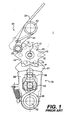
- a conventional gear selector mechanism 1 for a transmission is illustrated in Fig. 1.
- the gear selector mechanism 1 includes an indexing plate 10 that rotates about an axis 11.
- the indexing plate 10 is secured to one side of a gear selector drum (not shown).
- the indexing plate 10 includes a plurality of cylindrical indexing pins 12 secured thereto.
- a plurality of notches 13 are formed in the periphery of the indexing plate 10 between the cylindrical indexing pins 12.
- the number of notches 13 corresponds to the number of gear positions and the neutral gear position.
- the gear selector mechanism 1 further includes an indexing lever 20.
- the indexing lever 20 includes an indexing arm 21 that is pivotally mounted at one end to a housing (not shown) of the transmission through a pivot pin 22.
- a free end of the indexing arm 21 includes a positioning pin 23.
- the positioning pin 23 is received within the notches 13.
- the indexing lever 20 is biased by a spring 24 into the notches 13.
- the gear selector mechanism 1 also includes a selector 30.
- the selector 30 includes a selector pawl 31 that is pivotally mounted the housing of the transmission about a selector shaft 32.
- the selector shaft 32 extends out of the housing and supports a selector lever (not shown).
- a cylindrical pin 33 is fixed to the housing between the selector shaft 32 and the indexing plate 10.
- a spring 34 extends around the selector shaft 32 and along the sides of the cylindrical pin 33. The spring 34 holds the selector pawl 31 in a normal position.
- One end of the selector pawl 31 is adapted to engage the indexing pins 12 and rotate the indexing plate 10 about the axis 11. This is accomplished by the selector pawl 31 pivoting about the axis to a position P, shown in phantom, in Fig. 1.
- the other end of the selector pawl 31 pivots about the selector shaft 32.
- a selector lever 35 is provided in order to pivot the selector pawl 31 when the selector shaft 32 is rotated.
- the selector lever 35 is connected to the selector shaft 32 such that it rotates therewith.
- the selector lever 35 supports a selector pin 36.
- the selector pin 36 moves with the selector lever 35 and is in contact with the spring 34 such that selector pawl 31 and the selector lever 35 return from the position P to the normal position, shown in Fig. 1, under the bias of the spring 34.
- Conversion of the pivoting motion of the selector pawl 31 into the rotary motion of the gear selector drum through the indexing plate 10 is effected by the mechanical interaction of the selector pawl 31 and a plurality of cylindrical pins 12.
- the selector shaft 32 and selector lever 35 are rotated, which causes the selector pawl 31 to pivot.
- the selector pawl 31 engages the cylindrical pins 12 causing the indexing plate to rotate. This causes the positioning pin 23 of the indexing lever 20 to be lifted out of one particular notch 13 and then pressed into the next notch 13 by a spring 24. This requires a defined selection force that is necessary to complete the gear change.
- the geometrical relationships of the selector mechanism 1 have proven to be disadvantageous because the selection force that must be applied to complete a gear change is at its maximum at the beginning and the end of the gear-change operation, and is minimal at the time the next gear is engaged. This arrangement reduces the speed at which gear changes can be made, and greatly increase the amount of force that has to be applied to complete such gear change operations.
- the gear selector mechanism includes a selector pawl pivotally mounted about a shaft.
- the gear selector mechanism also includes a rotatable gear shift plate having a plurality of radially extending teeth extending around a periphery thereof.
- the gear shift plate replaces prior art cylindrical pins.
- Each of the plurality of teeth having an outer tip and an inner base portion.
- At least a portion of the selector pawl is adapted to selectively engage at least one of the teeth during the gear shifting operation.
- the selector pawl engages one of the plurality of teeth in an area adjacent the outer tip at a beginning of the gear shifting operation.
- the gear shift plate functions in such a way that at the beginning of the gear change process the point of contact between the selector pawl and the gear shift plate is located at the greatest possible distance from the center of rotation of the gear selector drum and thereby at the shortest distance from the center of rotation of the selector pawl.
- the selection force at the selector pawl is significantly reduced as compared to the prior art selector mechanisms.
- the relationship of the forces is similar to that in the prior art system described above.
- the selector pawl further engages one of the plurality of teeth in an area adjacent the inner base portion at the end of the gear shift operation.
- the point at which force is applied at the end of the gear shift operation is thus located at the minimal distance from the center of rotation of the gear selector drum and thus at the greatest possible distance from the selector pawl, so that a transition from the selector pawl to the gear selector drum takes place very quickly.
- gear shift operations can be completed as rapidly as possible.
- the gear selector mechanism in accordance with the present invention further includes a rotatable indexing plate having a plurality of recesses formed in an outer periphery thereof. Each of the plurality of recesses corresponds to one of a neutral position and a plurality of gear positions.
- the rotatable gear shift plate and the rotatable indexing plate may rotate about a common axis.
- the rotatable indexing plate and the rotatable gear shift plate are arranged such that each recess has a pair of the teeth positioned on opposing sides of the recess.
- the gear selector mechanism in accordance with the present invention further includes a pivoting indexing lever. The indexing lever is adapted to be positioned in one of the plurality of recesses at the completion of the gear changing operation.
- the selector pawl may include a pair of fingers.
- the pair of fingers are arranged on the selector pawl such the fingers are located on opposing sides of two adjacent teeth in an inoperative position or normal position.
- One of the fingers engages one tooth in the area adjacent the outer tip at a beginning of the gear shifting operation.
- the finger engages the one tooth in the area adjacent the inner base portion at the end of the gear shift operation. The arrangement helps achieve the reduction in selection force.
- the gear selector mechanism includes a selector shaft.
- the selector pawl may be pivotably and slidably mounted to the selector shaft. It is contemplated that the selector pawl pivots about the selector shaft during the gear changing operation.
- the selector pawl pivots about the shaft and slides a predetermined distance at the conclusion of the gear changing operation such that selector pawl returns to the initial position or inoperative position.
- each finger includes a surface adapted to contact one of the teeth at the completion of the gear change operation as the selector pawl returns to the initial position. The contact between the surface and the one tooth causes the selector pawl to slide a predetermined distance away from the selector shaft.
- the gear selection mechanism may further include at least one spring operatively coupled to the selector pawl for returning the selector pawl to the initial position at the completion of the gear change operation.
- Fig. 1 is an enlarged side view of a gear selector mechanism as described in the prior art
- Fig. 2 is an enlarged side view of a gear selector mechanism in accordance with a first embodiment of the present invention, wherein the gear selector mechanism is illustrated in a position at the beginning of a gear shift operation;
- Fig. 3 is an enlarged side view of the gear selector mechanism of Fig. 2, wherein the gear selector mechanism is illustrated in a position at the end of the gear shift operation;
- Fig. 4 is an enlarged side view of a gear selector mechanism according to a second embodiment of the present invention.
- Fig. 5 is an enlarged side view of the gear selector mechanism of Fig. 4, wherein the gear selector mechanism is illustrated in a position at the beginning of a gear shift operation;
- Fig. 6 is an enlarged side view of the gear selector mechanism of Fig. 4, wherein the gear selector mechanism is illustrated in a position at the end of the gear shift operation;
- Fig. 7 is an enlarged side view of a gear selector mechanism in accordance with a third embodiment of the present invention, wherein the gear selector mechanism is illustrated in a position at the beginning of a gear shift operation;
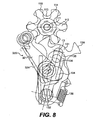
- Fig. 8 is an enlarged side view of the gear selector mechanism of Fig. 7, wherein the gear selector mechanism is illustrated in a position at the end of the gear shift operation;
- Fig. 9 is an enlarged side view of a gear selector mechanism in accordance with a fourth embodiment of the present invention, wherein the gear selector mechanism is illustrated in a position at the beginning of a gear shift operation;
- Fig. 10 is an enlarged side view of the gear selector mechanism of Fig. 7, wherein the gear selector mechanism is illustrated in a position at the end of the gear shift operation.
- a gear selector mechanism 100 for a transmission in accordance with one embodiment of the present invention is illustrated in Figs. 2 and 3.
- the gear selector mechanism 100 includes an indexing plate 110 that rotates about an axis 111.
- the indexing plate 110 is secured to one side of a gear selector drum (not shown).
- the indexing plate 110 includes a gear shift plate 112 secured thereto.
- the gear shift plate 112 and the indexing plate 110 rotate about the axis 111.
- a plurality of notches 113 are formed in the periphery of the indexing plate 110.
- the number of notches 113 corresponds to the number of gear positions and the neutral gear position.
- the gear shift plate 112 resembles a gear wheel and includes a plurality of indexing teeth 114.
- the indexing teeth 114 are positioned between each of the notches 113, as shown in Figs. 2 and 3.
- the gear shift plate 112 Since the gear shift plate 112 is attached to the indexing plate 110, the indexing plate 110 increases the sturdiness of the plate 112.
- the gear shift plate 112 may be stamped from metal or formed from an inexpensive sintered metal part.
- the gear selector mechanism 100 further includes an indexing lever 120.
- the indexing lever 120 includes an indexing arm 121 that is pivotally mounted at one end to a housing (not shown) of the transmission through a pivot pin 122.
- a free end of the indexing arm 121 includes a positioning pin 123.
- the positioning pin 123 is received within the notches 113.
- the indexing lever 120 is radially biased by a spring 124 into the notches 113.
- the positioning pin 123 is located in one of the notches 113 in the neutral position and the defined gear positions.
- the positioning pin 123 and the notches 113 define the predetermined positions of the indexing plate 110 for the individual gears, and thereby define an angle between two adjacent notches 113 through which the indexing plate 110 must be rotated in order to shift from one gear to another.
- the indexing plate 110 is rotated about the axis 111 through an angle subtended by two notches 113.
- the gear selector mechanism 100 also includes a selector 130.
- the selector 130 includes a selector pawl 131 that is pivotally mounted the housing of the transmission about a selector shaft 132.
- the selector shaft 132 extends out of the housing.
- the force necessary to operate the gear selector mechanism 100 is provided through the selector shaft 132.
- the selector shaft 132 is operatively coupled to an external assembly such as a manually operated foot shift mechanism (not shown) such that the force applied by a driver's foot is transferred by the selector shaft 132 to operate the gear selector mechanism 100.
- the present invention is not to be limited to solely a foot driven shaft mechanism; rather, other mechanically driven assemblies are considered to be well within the scope of the present invention.
- the selector shaft 132 may be rotated by an automatic shifting mechanism that may be operated by an electric motor or suitable electromagnetic device that is capable of rotating the selector shaft 132.
- a cylindrical pin 133 is fixed to the housing between the selector shaft 132 and the indexing plate 110.
- a spring 134 extends around the selector shaft 132 and along the sides of the cylindrical pin 133. The spring 134 holds the selector pawl 131 in a normal position.
- the spring 134 is preferably a hairpin spring having legs located on opposing sides of the cylindrical pin 133.
- the present invention is not limited to the use of hairpin springs; rather, other springs that are capable of returning the selector pawl 131 are considered to be well within the scope of the present invention.
- the selector pawl 131 may be forked at both ends.
- One end of the selector pawl 131 is adapted to engage the indexing teeth 114 and rotate the indexing plate 110 and the gear shift plate 112 about the axis 111. This is accomplished by the selector pawl 131 pivoting about the axis from the position shown in Fig. 2 to the position shown in Fig. 3.
- the other forked end of the selector pawl 131 pivots about the selector shaft 132. It is not necessary for this end of the selector pawl 131 to have a forked construction; rather, any construction that permits the selector pawl 131 to pivot about the selector shaft 132 and move in the direction A is considered to be well within the scope of the present invention.
- a slot may be provided In order to pivot the selector pawl 131 when the selector shaft 132 is rotated, a selector lever 135 is provided.
- the selector lever 135 is connected to the selector shaft 132 such that it rotates therewith.
- the selector lever 135 supports a selector pin 136. Free ends of the spring 134 are located on opposing sides of the selector pin 136.
- the selector pin 136 is slidably received within a groove 137 formed in the selector pawl 131.
- the selector pin 136 moves with the selector lever 135 and is in contact with the spring 134 such that selector pawl 131 and the selector lever 135 return from the position, shown in Fig. 3 to the normal position, shown in Fig.
- the selector pawl 131 is supported so as to be able to slide in the direction indicated by the arrow A and thus radially with respect to the axis of the selector shaft 132 against the resistance of a spring 138, and thereby be adjustable relative to the lever arm 120.
- the start of the gear shift operation is shown in Fig. 2.
- the selector pawl 131 is held in its normal position by the spring 134 and the spring 138.
- the point of contact between the selector pawl 131 and the gear shift plate 112 is in the area of the tip of one indexing tooth 114.
- the point of application of force is at the greatest possible distance Y from the center of rotation of the gear shift plate 112, and thus from the gear selector drum.
- This arrangement results in a minimal lever arm X for the selector pawl 131.
- the selector pawl 131 can pivot in either a clockwise direction or a counter clockwise direction based upon the direction of rotation of the selector shaft 132.
- the end of the gear shift operation is shown in Fig. 3.
- the selector pawl 131 and the selector lever 135 have been rotated out of its normal position.
- the point of contact between the selector pawl 131 and the gear shift plate 112 is in the area of the foot of one of the indexing teeth 117.
- the selector pawl 131 is located closer to the center of rotation of the gear shift plate 112. This increases the speed in which the gear shift plate 112 and the selector pawl 131 move with respect to each other. This has a positive effect in that a gear change is completed more rapidly.
- the hairpin spring 134 moves the selector pawl 131 back into its normal position, as shown in Fig. 2.
- a back portion 139 of the selector pawl 131 rests on the gear shift plate 112, whereupon the selector pawl 131 moves out of the way of the gear shift plate 112 as it pivots back into its normal position in the direction indicated by the arrow A, against the resistance of the spring 138.
- the above described arrangement makes it possible to achieve a significant reduction in the force that has to be applied in order to shift gears, while using a similar indexing lever, similar gear shift travel, and a similar spring.
- the gear selector mechanism 200 includes an indexing plate 110 and gear shift plate 112, as described above.
- the gear selector mechanism 200 further includes an indexing lever 220.
- the indexing lever 220 includes an indexing arm 221 that is pivotally mounted at one end to a housing (not shown) of the transmission through a selector shaft 232.
- a free end of the indexing arm 221 includes a positioning pin 223.
- the positioning pin 223 is received within the notches 113.
- the indexing lever 220 is radially biased by a spring 224 into the notches 113.
- the positioning pin 223 is located in one of the notches 113 in the neutral position and the defined gear positions.
- the gear selector mechanism 200 also includes a selector 230.
- the selector 230 includes a selector pawl 231 that is pivotally mounted the housing of the transmission about a selector shaft 232.
- the selector shaft 232 extends out of the housing and supports a selector lever (not shown).
- the selector pawl 231 has an opening 233 formed in an interior portion.
- the indexing plate 110 and the gear shift plate 112 rotate about the axis 111 within the opening 233.
- the indexing plate 110 remains within the opening 233 as the selector pawl 231 pivots during the gear changing operation.
- the selector pawl 231 includes a pair of fingers 234 are adapted to engage the teeth 114 of the gear shift plate 112.
- the selector pawl 231 can pivot in either a clockwise direction or a counter clockwise direction based upon the direction of rotation of the selector shaft 232.
- the range of motion of the selector pawl 231 is illustrated in phantom in Fig. 4.
- a selector lever 235 is provided in order to pivot the selector pawl 231 when the selector shaft 232 is rotated.
- the selector lever 235 is connected to the selector shaft 232 such that it rotates therewith.
- the selector lever 235 supports a selector pin 236.
- the selector pin 236 is slidably received within a groove 237 formed in the selector pawl 231.
- the selector pawl 231 is mounted on a selector shaft 232 so as to be able to slide in the direction indicated by the arrow A1 and thus be adjustable.
- the selector pin 236 moves with the selector lever 235.
- the selector lever 235 also includes an opening 238 formed therein.
- the shaft of the axis 111 is received within the opening 238, such that the selector pawl 231 and the selector lever 235 can rotate to the positions shown in Figs. 4 and 6.
- a return spring 238 is received on the selector shaft 232. As shown in Fig. 5, the return spring 239 includes legs that extend on opposing sides of the axis 111. The spring 239 also contacts the selector pin 236.
- the start of the gear shift operation is shown in Fig. 5.
- the selector pawl 231 is held in its normal position by the spring 239 and the spring 240.
- the point of contact between the selector pawl 131 and the gear shift plate 112 is in the area of the tip of one indexing tooth 114.
- the point of application of force is at the greatest possible distance from the center of rotation of the gear shift plate 112, and thus from the gear selector drum.
- This arrangement results in a minimal lever arm for the selector pawl 231. As such, the shifting moment that is required on the selector shaft 132 is reduced at the start of the gear shift operation.
- the end of the gear shift operation is shown in Fig. 6.
- the selector pawl 231 and the selector lever 235 have been rotated out of its normal position.
- the point of contact between the selector pawl 231 and the gear shift plate 112 is in the area between the fingers 234 and a foot of one of the indexing teeth 117, as shown in Fig. 6.
- the selector pawl 131 is located closer to the center of rotation of the gear shift plate 112. Engagement of the next gear is facilitated when the positioning pin 223 is pressed into one of the notches 113 by the spring 224.
- the indexing lever 220 helps define the conclusion of the gear shift operation precisely.
- the spring 238 moves the selector pawl 231 back into its normal position, as shown in Fig. 5.
- a back portion 241 of the selector pawl 231 rests on the gear shift plate 112, whereupon the selector pawl 231 moves out of the way of the gear shift plate 112 as it pivots back into its normal position in the direction indicated by the arrow A1, against the resistance of the spring 240.
- the gear selector mechanism 300 has a construction similar to the gear selector mechanism 100, described above. For the sake of brevity, the description of the common shared components will not be duplicated.
- the gear selector mechanism 300 includes a cylindrical pin 333.
- the cylindrical pin 333 performs substantially the same function as the cylindrical pin 133, described above.
- an indexing lever 320 is also pivotally mounted to the cylindrical pin 333.
- the indexing lever 320 includes an indexing arm 321 that is pivotally mounted at one end to the cylindrical pin 333.
- a free end of the indexing arm 321 includes a positioning pin 323.
- the positioning pin 323 is biased into the notches 113 by spring 324 in the manner described above in connection with the selector mechanism 100.
- the gear selector mechanism 300 operates in substantially the same manner, as the selector mechanism 100.
- gear selector mechanism 400 for a transmission in accordance with another embodiment of the present invention illustrated in Figs. 9 and 10 will now be described in greater detail.
- the gear selector mechanism 400 includes an indexing plate 110 and gear shift plate 112 having the construction described above.
- the gear selector mechanism 400 further includes an indexing lever 420.
- the indexing lever 420 includes an indexing arm 421 that is pivotally mounted at one end to a housing (not shown) of the transmission through a selector shaft 432.
- the selector 430 described below is also attached to the selector shaft 432.
- a free end of the indexing arm 421 includes a positioning pin 423.
- the positioning pin 423 is received within the notches 113.
- the indexing lever 420 is radially biased by a spring 424 into the notches 113.
- the positioning pin 423 is located in one of the notches 113 in the neutral position and the defined gear positions.
- the gear selector mechanism 400 also includes a selector 430.
- the selector 130 includes a selector pawl 431 that is pivotally mounted to one end of a selector lever 433.
- One end of the selector lever 433 is pivotally mounted to the selector shaft 432.
- the selector lever 433 includes a central opening 434 formed therein.
- a stop 435 is positioned within the opening 434.
- the stop 435 is mounted to the housing of the transmission.
- An opposite end of the selector lever 433 includes a selector pin 436 mounted thereon.
- the selector pawl 431 is pivotally mounted at one end to the selector pin 436.
- An opposite end of the selector pawl 431 includes a pair of fingers 437.
- the fingers 437 are adapted to engage the indexing teeth 114 and rotate the indexing plate 110 and the gear shift plate 112 about the axis 111.
- a spring 438 is operatively connected to the selector lever 433 and the selector pawl 431 to bias the selector pawl 431 into contact with the gear shift plate 112, as shown in Fig. 9.
- a spring 439 extends around the selector shaft 432 and along opposing sides of the stop 435 and the selector pin 436. The spring 439 provides the return force to return the selector 430 to the normal position, shown in Fig. 9, at the completion of the gear change operation.
- the start of the gear shift operation is shown in Fig. 9.
- the selector pawl 431 is held in its normal position by the spring 438 and the spring 439.
- the selector lever 433 is pivoted, this causes the selector pawl 431 to move a direction substantially transverse to the axis of the selector lever 433.
- one of the pair of fingers 437 engages one of the teeth 114 to rotate the gear shift plate 112.
- the finger 437 that engages the teeth 114 is determined based upon the rotation of the selector shaft 432.
- the selector shaft 432 is pivoted in a clock-wise direction, the inner finger 437 engages one of the teeth 114, as shown in Fig.
- the end of the gear shift operation is shown in Fig. 11.
- the selector pawl 431 and the selector lever 433 have been rotated out of its normal position.
- the point of contact between the selector pawl 431 and the gear shift plate 112 is in the area of the foot of one of the indexing teeth 117.
- the selector pawl 431 is located closer to the center of rotation of the gear shift plate 112. This increases the speed in which the gear shift plate 112 and the selector pawl 431 move with respect to each other. This has a positive effect in that a gear change is completed more rapidly.
- the indexing lever 420 helps define the conclusion of the gear shift operation precisely. Once the gear shift operation has been concluded, the spring 438 moves the selector lever 433 back into its normal position, as shown in Fig. 9. When this occurs, a back portion 442 of the fingers 437 rests on the gear shift plate 112, whereupon the selector pawl 431 moves out of the way of the gear shift plate 112 against the resistance of the spring 439.
Landscapes
- Engineering & Computer Science (AREA)
- Mechanical Engineering (AREA)
- Chemical & Material Sciences (AREA)
- Combustion & Propulsion (AREA)
- Transportation (AREA)
- General Engineering & Computer Science (AREA)
- Gear-Shifting Mechanisms (AREA)
- Transmitters (AREA)
Abstract
Description
- This application claims priority to U.S. Provisional Patent Application No. 60/367,726, which was filed on March 28, 2002.
- The present invention relates to a gear selector mechanism for a transmission as used, in particular, in motorcycles and other recreational vehicles such as ATV's, karts, scooters, etc. Most transmissions of this kind have a gear selector drum that manages gear changes by way of selector forks, selector pinions, and dog clutches. The gear selector drum is rotated by a selector pawl that is secured to a selector shaft.
- A conventional
gear selector mechanism 1 for a transmission is illustrated in Fig. 1. Thegear selector mechanism 1 includes anindexing plate 10 that rotates about anaxis 11. Theindexing plate 10 is secured to one side of a gear selector drum (not shown). Theindexing plate 10 includes a plurality ofcylindrical indexing pins 12 secured thereto. A plurality ofnotches 13 are formed in the periphery of theindexing plate 10 between thecylindrical indexing pins 12. The number ofnotches 13 corresponds to the number of gear positions and the neutral gear position. Thegear selector mechanism 1 further includes anindexing lever 20. The indexinglever 20 includes an indexingarm 21 that is pivotally mounted at one end to a housing (not shown) of the transmission through apivot pin 22. A free end of the indexingarm 21 includes apositioning pin 23. Thepositioning pin 23 is received within thenotches 13. The indexinglever 20 is biased by aspring 24 into thenotches 13. Thegear selector mechanism 1 also includes aselector 30. Theselector 30 includes aselector pawl 31 that is pivotally mounted the housing of the transmission about aselector shaft 32. Theselector shaft 32 extends out of the housing and supports a selector lever (not shown). Acylindrical pin 33 is fixed to the housing between theselector shaft 32 and theindexing plate 10. Aspring 34 extends around theselector shaft 32 and along the sides of thecylindrical pin 33. Thespring 34 holds theselector pawl 31 in a normal position. One end of theselector pawl 31 is adapted to engage the indexingpins 12 and rotate theindexing plate 10 about theaxis 11. This is accomplished by theselector pawl 31 pivoting about the axis to a position P, shown in phantom, in Fig. 1. The other end of theselector pawl 31 pivots about theselector shaft 32. In order to pivot theselector pawl 31 when theselector shaft 32 is rotated, aselector lever 35 is provided. Theselector lever 35 is connected to theselector shaft 32 such that it rotates therewith. Theselector lever 35 supports aselector pin 36. Theselector pin 36 moves with theselector lever 35 and is in contact with thespring 34 such thatselector pawl 31 and the selector lever 35 return from the position P to the normal position, shown in Fig. 1, under the bias of thespring 34. - Conversion of the pivoting motion of the
selector pawl 31 into the rotary motion of the gear selector drum through theindexing plate 10 is effected by the mechanical interaction of theselector pawl 31 and a plurality ofcylindrical pins 12. When it is desirable to shift from one gear position into the next gear position, theselector shaft 32 andselector lever 35 are rotated, which causes theselector pawl 31 to pivot. Theselector pawl 31 engages thecylindrical pins 12 causing the indexing plate to rotate. This causes the positioningpin 23 of the indexinglever 20 to be lifted out of oneparticular notch 13 and then pressed into thenext notch 13 by aspring 24. This requires a defined selection force that is necessary to complete the gear change. The geometrical relationships of theselector mechanism 1 have proven to be disadvantageous because the selection force that must be applied to complete a gear change is at its maximum at the beginning and the end of the gear-change operation, and is minimal at the time the next gear is engaged. This arrangement reduces the speed at which gear changes can be made, and greatly increase the amount of force that has to be applied to complete such gear change operations. - Another gear selector mechanism is described in US Patent No. 4,510,820 to Tsuboi. In this gear selector mechanism, the transmission of force from the gear change pedal to the gear selector drum using an epicyclic gearing. This gearing greatly increases the cost of a gear selector drum drive.
- It is an object of the present invention to provide an easy shifting transmission mechanism for a vehicle.
- It is another object of the present invention to provide an easy shifting transmission that requires a small amount of force at the beginning of the gear change process.
- It is another object of the present invention to provide an easy shifting transmission that engages the next gear as quickly as possible.
- It is another object of the present invention to provide an easy shifting transmission having a gear shift plate.
- It is another object of the present invention to provide an easy shifting transmission having a gear shift plate that functions in such a way that at the beginning of the gear change process, the point of contact between a selector pawl and the gear shift plate is located at the greatest possible distance from the axis of rotation of the gear selector drum and thereby at the shortest distance from the center of rotation of the selector pawl, so that the force applied by the selector pawl is significantly reduced.
- It is another object of the present invention to provide a gear shift mechanism reduces the force required to shift gears.
- In response to the foregoing challenges, applicants have developed in accordance with claim 1 a novel gear selector mechanism for a transmission for performing a gear shifting operation at reduced forces. The gear selector mechanism includes a selector pawl pivotally mounted about a shaft. The gear selector mechanism also includes a rotatable gear shift plate having a plurality of radially extending teeth extending around a periphery thereof. The gear shift plate replaces prior art cylindrical pins. Each of the plurality of teeth having an outer tip and an inner base portion. At least a portion of the selector pawl is adapted to selectively engage at least one of the teeth during the gear shifting operation. The selector pawl engages one of the plurality of teeth in an area adjacent the outer tip at a beginning of the gear shifting operation. The gear shift plate functions in such a way that at the beginning of the gear change process the point of contact between the selector pawl and the gear shift plate is located at the greatest possible distance from the center of rotation of the gear selector drum and thereby at the shortest distance from the center of rotation of the selector pawl. Thus, the selection force at the selector pawl is significantly reduced as compared to the prior art selector mechanisms. In the middle position, where one gear has just been released and the next gear has not yet been selected, the relationship of the forces is similar to that in the prior art system described above.
- The selector pawl further engages one of the plurality of teeth in an area adjacent the inner base portion at the end of the gear shift operation. The point at which force is applied at the end of the gear shift operation is thus located at the minimal distance from the center of rotation of the gear selector drum and thus at the greatest possible distance from the selector pawl, so that a transition from the selector pawl to the gear selector drum takes place very quickly. Thus, gear shift operations can be completed as rapidly as possible.
- The gear selector mechanism in accordance with the present invention further includes a rotatable indexing plate having a plurality of recesses formed in an outer periphery thereof. Each of the plurality of recesses corresponds to one of a neutral position and a plurality of gear positions. The rotatable gear shift plate and the rotatable indexing plate may rotate about a common axis. The rotatable indexing plate and the rotatable gear shift plate are arranged such that each recess has a pair of the teeth positioned on opposing sides of the recess. The gear selector mechanism in accordance with the present invention further includes a pivoting indexing lever. The indexing lever is adapted to be positioned in one of the plurality of recesses at the completion of the gear changing operation.
- The selector pawl may include a pair of fingers. The pair of fingers are arranged on the selector pawl such the fingers are located on opposing sides of two adjacent teeth in an inoperative position or normal position. One of the fingers engages one tooth in the area adjacent the outer tip at a beginning of the gear shifting operation. The finger engages the one tooth in the area adjacent the inner base portion at the end of the gear shift operation. The arrangement helps achieve the reduction in selection force.
- In accordance with the present invention, the gear selector mechanism includes a selector shaft. The selector pawl may be pivotably and slidably mounted to the selector shaft. It is contemplated that the selector pawl pivots about the selector shaft during the gear changing operation. The selector pawl pivots about the shaft and slides a predetermined distance at the conclusion of the gear changing operation such that selector pawl returns to the initial position or inoperative position. In accordance with the present invention, each finger includes a surface adapted to contact one of the teeth at the completion of the gear change operation as the selector pawl returns to the initial position. The contact between the surface and the one tooth causes the selector pawl to slide a predetermined distance away from the selector shaft. The gear selection mechanism may further include at least one spring operatively coupled to the selector pawl for returning the selector pawl to the initial position at the completion of the gear change operation.
- The invention will be described in conjunction with the following drawings in which like reference numerals designate like elements and wherein:
- Fig. 1 is an enlarged side view of a gear selector mechanism as described in the prior art;
- Fig. 2 is an enlarged side view of a gear selector mechanism in accordance with a first embodiment of the present invention, wherein the gear selector mechanism is illustrated in a position at the beginning of a gear shift operation;
- Fig. 3 is an enlarged side view of the gear selector mechanism of Fig. 2, wherein the gear selector mechanism is illustrated in a position at the end of the gear shift operation;
- Fig. 4 is an enlarged side view of a gear selector mechanism according to a second embodiment of the present invention;
- Fig. 5 is an enlarged side view of the gear selector mechanism of Fig. 4, wherein the gear selector mechanism is illustrated in a position at the beginning of a gear shift operation;
- Fig. 6 is an enlarged side view of the gear selector mechanism of Fig. 4, wherein the gear selector mechanism is illustrated in a position at the end of the gear shift operation;
- Fig. 7 is an enlarged side view of a gear selector mechanism in accordance with a third embodiment of the present invention, wherein the gear selector mechanism is illustrated in a position at the beginning of a gear shift operation;
- Fig. 8 is an enlarged side view of the gear selector mechanism of Fig. 7, wherein the gear selector mechanism is illustrated in a position at the end of the gear shift operation;
- Fig. 9 is an enlarged side view of a gear selector mechanism in accordance with a fourth embodiment of the present invention, wherein the gear selector mechanism is illustrated in a position at the beginning of a gear shift operation; and
- Fig. 10 is an enlarged side view of the gear selector mechanism of Fig. 7, wherein the gear selector mechanism is illustrated in a position at the end of the gear shift operation.
- A
gear selector mechanism 100 for a transmission in accordance with one embodiment of the present invention is illustrated in Figs. 2 and 3. Thegear selector mechanism 100 includes anindexing plate 110 that rotates about anaxis 111. Theindexing plate 110 is secured to one side of a gear selector drum (not shown). Theindexing plate 110 includes agear shift plate 112 secured thereto. Thegear shift plate 112 and theindexing plate 110 rotate about theaxis 111. A plurality ofnotches 113 are formed in the periphery of theindexing plate 110. The number ofnotches 113 corresponds to the number of gear positions and the neutral gear position. Thegear shift plate 112 resembles a gear wheel and includes a plurality ofindexing teeth 114. Theindexing teeth 114 are positioned between each of thenotches 113, as shown in Figs. 2 and 3. - Since the
gear shift plate 112 is attached to theindexing plate 110, theindexing plate 110 increases the sturdiness of theplate 112. Thegear shift plate 112 may be stamped from metal or formed from an inexpensive sintered metal part. - The
gear selector mechanism 100 further includes anindexing lever 120. Theindexing lever 120 includes anindexing arm 121 that is pivotally mounted at one end to a housing (not shown) of the transmission through apivot pin 122. A free end of theindexing arm 121 includes apositioning pin 123. Thepositioning pin 123 is received within thenotches 113. Theindexing lever 120 is radially biased by aspring 124 into thenotches 113. Thepositioning pin 123 is located in one of thenotches 113 in the neutral position and the defined gear positions. Thepositioning pin 123 and thenotches 113 define the predetermined positions of theindexing plate 110 for the individual gears, and thereby define an angle between twoadjacent notches 113 through which theindexing plate 110 must be rotated in order to shift from one gear to another. During the gear shift operation described below, theindexing plate 110 is rotated about theaxis 111 through an angle subtended by twonotches 113. - The
gear selector mechanism 100 also includes aselector 130. Theselector 130 includes aselector pawl 131 that is pivotally mounted the housing of the transmission about aselector shaft 132. Theselector shaft 132 extends out of the housing. The force necessary to operate thegear selector mechanism 100 is provided through theselector shaft 132. Theselector shaft 132 is operatively coupled to an external assembly such as a manually operated foot shift mechanism (not shown) such that the force applied by a driver's foot is transferred by theselector shaft 132 to operate thegear selector mechanism 100. The present invention, however, is not to be limited to solely a foot driven shaft mechanism; rather, other mechanically driven assemblies are considered to be well within the scope of the present invention. It is further contemplated that theselector shaft 132 may be rotated by an automatic shifting mechanism that may be operated by an electric motor or suitable electromagnetic device that is capable of rotating theselector shaft 132. Acylindrical pin 133 is fixed to the housing between theselector shaft 132 and theindexing plate 110. Aspring 134 extends around theselector shaft 132 and along the sides of thecylindrical pin 133. Thespring 134 holds theselector pawl 131 in a normal position. Thespring 134 is preferably a hairpin spring having legs located on opposing sides of thecylindrical pin 133. The present invention, however, is not limited to the use of hairpin springs; rather, other springs that are capable of returning theselector pawl 131 are considered to be well within the scope of the present invention. - The
selector pawl 131 may be forked at both ends. One end of theselector pawl 131 is adapted to engage theindexing teeth 114 and rotate theindexing plate 110 and thegear shift plate 112 about theaxis 111. This is accomplished by theselector pawl 131 pivoting about the axis from the position shown in Fig. 2 to the position shown in Fig. 3. The other forked end of theselector pawl 131 pivots about theselector shaft 132. It is not necessary for this end of theselector pawl 131 to have a forked construction; rather, any construction that permits theselector pawl 131 to pivot about theselector shaft 132 and move in the direction A is considered to be well within the scope of the present invention. For example, a slot may be provided In order to pivot theselector pawl 131 when theselector shaft 132 is rotated, aselector lever 135 is provided. Theselector lever 135 is connected to theselector shaft 132 such that it rotates therewith. Theselector lever 135 supports aselector pin 136. Free ends of thespring 134 are located on opposing sides of theselector pin 136. Theselector pin 136 is slidably received within agroove 137 formed in theselector pawl 131. Theselector pin 136 moves with theselector lever 135 and is in contact with thespring 134 such thatselector pawl 131 and theselector lever 135 return from the position, shown in Fig. 3 to the normal position, shown in Fig. 2, under the bias of thespring 134. Theselector pawl 131 is supported so as to be able to slide in the direction indicated by the arrow A and thus radially with respect to the axis of theselector shaft 132 against the resistance of aspring 138, and thereby be adjustable relative to thelever arm 120. - The start of the gear shift operation is shown in Fig. 2. The
selector pawl 131 is held in its normal position by thespring 134 and thespring 138. At the start of the gear shift operation, the point of contact between theselector pawl 131 and thegear shift plate 112 is in the area of the tip of oneindexing tooth 114. With this arrangement, at the start of the gear shift operation, the point of application of force is at the greatest possible distance Y from the center of rotation of thegear shift plate 112, and thus from the gear selector drum. This arrangement results in a minimal lever arm X for theselector pawl 131. As such, the shifting moment that is required on theselector shaft 132 is reduced at the start of the gear shift operation. Theselector pawl 131 can pivot in either a clockwise direction or a counter clockwise direction based upon the direction of rotation of theselector shaft 132. - The end of the gear shift operation is shown in Fig. 3. At the end of the gear shift operation, the
selector pawl 131 and theselector lever 135 have been rotated out of its normal position. At the end of the gear shift operation, the point of contact between theselector pawl 131 and thegear shift plate 112 is in the area of the foot of one of theindexing teeth 117. With this positioning, theselector pawl 131 is located closer to the center of rotation of thegear shift plate 112. This increases the speed in which thegear shift plate 112 and theselector pawl 131 move with respect to each other. This has a positive effect in that a gear change is completed more rapidly. Engagement of the next gear is facilitated when thepivot pin 122 is pressed into one of thenotches 113 by thespring 124. Theindexing lever 120 helps define the conclusion of the gear shift operation precisely. Once the gear shift operation has been concluded, thehairpin spring 134 moves theselector pawl 131 back into its normal position, as shown in Fig. 2. When this occurs, aback portion 139 of theselector pawl 131 rests on thegear shift plate 112, whereupon theselector pawl 131 moves out of the way of thegear shift plate 112 as it pivots back into its normal position in the direction indicated by the arrow A, against the resistance of thespring 138. - Unlike the prior art, there is no need to apply a greater amount of force at the end of the gear shift operation. In accordance with the present invention, the above described arrangement makes it possible to achieve a significant reduction in the force that has to be applied in order to shift gears, while using a similar indexing lever, similar gear shift travel, and a similar spring.
- A
gear selector mechanism 200 for a transmission in accordance with another embodiment of the present invention illustrated in Figs. 4-6 will now be described in greater detail. Like thegear selector mechanism 100, thegear selector mechanism 200 includes anindexing plate 110 andgear shift plate 112, as described above. Thegear selector mechanism 200 further includes anindexing lever 220. Theindexing lever 220 includes anindexing arm 221 that is pivotally mounted at one end to a housing (not shown) of the transmission through aselector shaft 232. Theindexing arm 221 and theselector pawl 231, described below, both rotate about theselector shaft 232. A free end of theindexing arm 221 includes apositioning pin 223. Thepositioning pin 223 is received within thenotches 113. Theindexing lever 220 is radially biased by aspring 224 into thenotches 113. Thepositioning pin 223 is located in one of thenotches 113 in the neutral position and the defined gear positions. - The
gear selector mechanism 200 also includes aselector 230. Theselector 230 includes aselector pawl 231 that is pivotally mounted the housing of the transmission about aselector shaft 232. Theselector shaft 232 extends out of the housing and supports a selector lever (not shown). Theselector pawl 231 has anopening 233 formed in an interior portion. Theindexing plate 110 and thegear shift plate 112 rotate about theaxis 111 within theopening 233. Theindexing plate 110 remains within theopening 233 as theselector pawl 231 pivots during the gear changing operation. Theselector pawl 231 includes a pair offingers 234 are adapted to engage theteeth 114 of thegear shift plate 112. With this arrangement, the distance between the gear selector drum and theselector shaft 232 is even shorter than the embodiment of Figs. 2 and 3. This arrangement also reduces the space required for the transmission. Theselector pawl 231 can pivot in either a clockwise direction or a counter clockwise direction based upon the direction of rotation of theselector shaft 232. The range of motion of theselector pawl 231 is illustrated in phantom in Fig. 4. - In order to pivot the
selector pawl 231 when theselector shaft 232 is rotated, aselector lever 235 is provided. Theselector lever 235 is connected to theselector shaft 232 such that it rotates therewith. Theselector lever 235 supports aselector pin 236. Theselector pin 236 is slidably received within agroove 237 formed in theselector pawl 231. Theselector pawl 231 is mounted on aselector shaft 232 so as to be able to slide in the direction indicated by the arrow A1 and thus be adjustable. Theselector pin 236 moves with theselector lever 235. Theselector lever 235 also includes anopening 238 formed therein. The shaft of theaxis 111 is received within theopening 238, such that theselector pawl 231 and theselector lever 235 can rotate to the positions shown in Figs. 4 and 6. Areturn spring 238 is received on theselector shaft 232. As shown in Fig. 5, thereturn spring 239 includes legs that extend on opposing sides of theaxis 111. Thespring 239 also contacts theselector pin 236. - The start of the gear shift operation is shown in Fig. 5. The
selector pawl 231 is held in its normal position by thespring 239 and thespring 240. At the start of the gear shift operation, the point of contact between theselector pawl 131 and thegear shift plate 112 is in the area of the tip of oneindexing tooth 114. Like the embodiment of Figs. 2 and 3, at the start of the gear shift operation, the point of application of force is at the greatest possible distance from the center of rotation of thegear shift plate 112, and thus from the gear selector drum. This arrangement results in a minimal lever arm for theselector pawl 231. As such, the shifting moment that is required on theselector shaft 132 is reduced at the start of the gear shift operation. - The end of the gear shift operation is shown in Fig. 6. At the end of the gear shift operation, the
selector pawl 231 and theselector lever 235 have been rotated out of its normal position. At the end of the gear shift operation, the point of contact between theselector pawl 231 and thegear shift plate 112 is in the area between thefingers 234 and a foot of one of theindexing teeth 117, as shown in Fig. 6. With this positioning, theselector pawl 131 is located closer to the center of rotation of thegear shift plate 112. Engagement of the next gear is facilitated when thepositioning pin 223 is pressed into one of thenotches 113 by thespring 224. Theindexing lever 220 helps define the conclusion of the gear shift operation precisely. Once the gear shift operation has been concluded, thespring 238 moves theselector pawl 231 back into its normal position, as shown in Fig. 5. When this occurs, aback portion 241 of theselector pawl 231 rests on thegear shift plate 112, whereupon theselector pawl 231 moves out of the way of thegear shift plate 112 as it pivots back into its normal position in the direction indicated by the arrow A1, against the resistance of thespring 240. - A
gear selector mechanism 300 for a transmission in accordance with another embodiment of the present invention illustrated in Figs. 7 and 8 will now be described in greater detail. Thegear selector mechanism 300 has a construction similar to thegear selector mechanism 100, described above. For the sake of brevity, the description of the common shared components will not be duplicated. Thegear selector mechanism 300 includes acylindrical pin 333. Thecylindrical pin 333 performs substantially the same function as thecylindrical pin 133, described above. In the embodiment illustrated in Figs. 7 and 8, anindexing lever 320 is also pivotally mounted to thecylindrical pin 333. Theindexing lever 320 includes anindexing arm 321 that is pivotally mounted at one end to thecylindrical pin 333. A free end of theindexing arm 321 includes apositioning pin 323. Thepositioning pin 323 is biased into thenotches 113 byspring 324 in the manner described above in connection with theselector mechanism 100. Thegear selector mechanism 300 operates in substantially the same manner, as theselector mechanism 100. - A
gear selector mechanism 400 for a transmission in accordance with another embodiment of the present invention illustrated in Figs. 9 and 10 will now be described in greater detail. Like thegear selector mechanisms gear selector mechanism 400 includes anindexing plate 110 andgear shift plate 112 having the construction described above. - The
gear selector mechanism 400 further includes anindexing lever 420. Theindexing lever 420 includes anindexing arm 421 that is pivotally mounted at one end to a housing (not shown) of the transmission through aselector shaft 432. Theselector 430 described below is also attached to theselector shaft 432. A free end of theindexing arm 421 includes apositioning pin 423. Thepositioning pin 423 is received within thenotches 113. Theindexing lever 420 is radially biased by aspring 424 into thenotches 113. Thepositioning pin 423 is located in one of thenotches 113 in the neutral position and the defined gear positions. - The
gear selector mechanism 400 also includes aselector 430. Theselector 130 includes aselector pawl 431 that is pivotally mounted to one end of aselector lever 433. One end of theselector lever 433 is pivotally mounted to theselector shaft 432. Theselector lever 433 includes acentral opening 434 formed therein. Astop 435 is positioned within theopening 434. Thestop 435 is mounted to the housing of the transmission. An opposite end of theselector lever 433 includes aselector pin 436 mounted thereon. Theselector pawl 431 is pivotally mounted at one end to theselector pin 436. An opposite end of theselector pawl 431 includes a pair offingers 437. Thefingers 437 are adapted to engage theindexing teeth 114 and rotate theindexing plate 110 and thegear shift plate 112 about theaxis 111. Aspring 438 is operatively connected to theselector lever 433 and theselector pawl 431 to bias theselector pawl 431 into contact with thegear shift plate 112, as shown in Fig. 9. Aspring 439 extends around theselector shaft 432 and along opposing sides of thestop 435 and theselector pin 436. Thespring 439 provides the return force to return theselector 430 to the normal position, shown in Fig. 9, at the completion of the gear change operation. - The start of the gear shift operation is shown in Fig. 9. The
selector pawl 431 is held in its normal position by thespring 438 and thespring 439. As theselector shaft 432 is rotated, theselector lever 433 is pivoted, this causes theselector pawl 431 to move a direction substantially transverse to the axis of theselector lever 433. With this arrangement, one of the pair offingers 437 engages one of theteeth 114 to rotate thegear shift plate 112. Thefinger 437 that engages theteeth 114 is determined based upon the rotation of theselector shaft 432. When theselector shaft 432 is pivoted in a clock-wise direction, theinner finger 437 engages one of theteeth 114, as shown in Fig. 10, which causes thegear shift plate 112 to rotate in a clock-wise direction. When theselector shaft 432 is pivoted in a counter clock-wise direction, theouter finger 437 engages one of theteeth 114, which causes thegear shift plate 112 to rotate in a counter clock-wise direction.Stops selector pawl 431. At the start of the gear shift operation, the point of contact between theselector pawl 431 and thegear shift plate 112 is in the area of the tip of oneindexing tooth 114. - The end of the gear shift operation is shown in Fig. 11. At the end of the gear shift operation, the
selector pawl 431 and theselector lever 433 have been rotated out of its normal position. At the end of the gear shift operation, the point of contact between theselector pawl 431 and thegear shift plate 112 is in the area of the foot of one of theindexing teeth 117. With this positioning, theselector pawl 431 is located closer to the center of rotation of thegear shift plate 112. This increases the speed in which thegear shift plate 112 and theselector pawl 431 move with respect to each other. This has a positive effect in that a gear change is completed more rapidly. - Engagement of the next gear is facilitated when the
pin 423 is pressed into one of thenotches 113 by thespring 424. Theindexing lever 420 helps define the conclusion of the gear shift operation precisely. Once the gear shift operation has been concluded, thespring 438 moves theselector lever 433 back into its normal position, as shown in Fig. 9. When this occurs, aback portion 442 of thefingers 437 rests on thegear shift plate 112, whereupon theselector pawl 431 moves out of the way of thegear shift plate 112 against the resistance of thespring 439. - While the invention has been described in connection with what is presently considered to be the most practical and preferred embodiments, it is to be understood that the invention is not to be limited to the disclosed embodiments and elements, but, to the contrary, is intended to cover various modifications, combinations of features, equivalent arrangements, and equivalent elements included within the scope of the appended claims. For example, the present invention has been described in connection with a transmission for use in motorcycles and other recreational vehicles. The present invention has broad application and it is intended that it may be used any mechanical assembly that requires the shifting between gear positions whereby the inclusion of the gear shift plate can lead to an overall reduction in the force necessary to shift from one gear position to another. Furthermore, the size of the various components that may appear in the drawings can vary from the size that may be portrayed in the figures herein. Thus, it is intended that the present invention covers the modifications and variations of the invention, provided they come within the scope of the appended claims and their equivalents.
Claims (14)
- A gear selector mechanism (100) for performing a gear shifting operation comprising:an indexing mechanism,a selector pawl (131) pivotally mounted about a selector shaft (132); andcharacterized by
a rotatable gear shift plate (112) having a plurality of radially extending teeth extending around a periphery thereof, wherein each of the plurality of teeth (114) having an outer tip and an inner base portion, wherein at least a portion of the selector pawl (131) is adapted to selectively engage at least one of the plurality of teeth (114) during the gear shifting operation, the selector pawl (131) engages one of the plurality of teeth in an area adjacent the outer tip at a beginning of the gear shifting operation and the selector pawl engages one of the plurality of teeth (114) in an area adjacent the inner base portion at the end of the gear shift operation. - The gear selector mechanism according to claim 1, wherein said
indexing mechanism comprises a rotatable indexing plate (110), the indexing plate having a plurality of recesses (113) formed in an outer periphery thereof, wherein each of the plurality of recesses corresponds to one of a neutral position and a plurality of gear positions, wherein the rotatable gear shift plate (112) and the rotatable indexing plate (110) rotate about a common axis (111), wherein the rotatable indexing plate and the rotatable gear shift plate are arranged such that each recess (113) has a pair of the teeth positioned on opposing sides of the recess. - The gear selector mechanism according to claim 1 or 2, further comprising:a pivoting indexing lever (120), wherein the indexing lever is positioned in one of the plurality of recesses at the completion of the gear changing operation.
- The gear selector mechanism according to one of claims I to 3, wherein the selector pawl (131) includes a pair of fingers (234), wherein the pair of fingers are arranged on the selector pawl such the fingers are located on opposing sides of two adjacent teeth in an inoperative position.
- The gear selector mechanism according to claim 4, wherein one of the fingers (234) engages one tooth (114) of the plurality of teeth in the area adjacent the outer tip at a beginning of the gear shifting operation and the finger engages the one tooth in the area adjacent the inner base portion at the end of the gear shift operation.
- The gear selector mechanism according to one of claims 1 to 5, wherein the selector pawl (131) is pivotably and slidably mounted to the selector shaft (132).
- The gear selector mechanism according to claim 6, wherein the selector pawl (131) pivots about the selector shaft (132) during the gear changing operation, wherein the selector pawl pivots and slides a predetermined distance at the completion of the gear changing operation such that selector pawl returns to an initial position.
- The gear selector mechanism according to claim 6 or 7, wherein the selector pawl (231) includes a pair of fingers (234), wherein each of the fingers includes a surface adapted to contact one of the teeth at the completion of the gear change operation as the selector pawl returns to the initial position, wherein the contact between the surface and the one tooth causes the selector pawl to slide a predetermined distance away from the selector shaft.
- The gear selector mechanism according to claim 7 or 8, further comprising:at least one spring (134) operatively coupled to the selector pawl (131) for returning the selector pawl to the initial position at the completion of the gear change operation.
- The gear selector mechanism according to one of claims 1 to 9, wherein the selector pawl (231) includes an opening (233) formed therein, wherein the rotatable gear shift plate is positioned within the opening.
- The gear selector mechanism according to claim 10, wherein the selector pawl (232) includes a pair of fingers (234), wherein the pair of fingers are arranged on the selector pawl such the fingers are located on opposing sides of two adjacent teeth in an inoperative position, wherein the pair of fingers extend into the opening (233).
- The gear selector mechanism according to one of claims 1 to 11, wherein the gear shift (112) plate is formed from metal, preferably from sintered metal.
- The gear selector mechanism according to one of claims I to 12, wherein the selector shaft (132) comprises a longitudinal axis, and wherein at least a part of the selector pawl (131) is movable with respect to the selector shaft (132) in a direction being at least partially perpendicular to the longitudinal axis of the shaft.
- The gear selector mechanism according to one of claims 1 to 8, wherein the selector shaft (132) comprises a longitudinal axis, and wherein at least a part of the selector pawl (131) is movable with respect to the selector shaft (132) in a direction being at least partially perpendicular to the longitudinal axis of the shaft and wherein the movement of the selector pawl (131) with respect to the selector shaft (132) is biased by at least one spring.
Applications Claiming Priority (2)
| Application Number | Priority Date | Filing Date | Title |
|---|---|---|---|
| US36772602P | 2002-03-28 | 2002-03-28 | |
| US367726P | 2002-03-28 |
Publications (3)
| Publication Number | Publication Date |
|---|---|
| EP1348618A2 EP1348618A2 (en) | 2003-10-01 |
| EP1348618A3 EP1348618A3 (en) | 2004-11-03 |
| EP1348618B1 true EP1348618B1 (en) | 2006-09-06 |
Family
ID=27805323
Family Applications (1)
| Application Number | Title | Priority Date | Filing Date |
|---|---|---|---|
| EP03006837A Expired - Lifetime EP1348618B1 (en) | 2002-03-28 | 2003-03-27 | Easy shifting transmission |
Country Status (4)
| Country | Link |
|---|---|
| US (1) | US20040003673A1 (en) |
| EP (1) | EP1348618B1 (en) |
| AT (1) | ATE338677T1 (en) |
| DE (1) | DE60308078T2 (en) |
Cited By (1)
| Publication number | Priority date | Publication date | Assignee | Title |
|---|---|---|---|---|
| CN103935461A (en) * | 2014-04-15 | 2014-07-23 | 石宗泽 | Sliding block type gear shifting device of bicycle miniature gearbox |
Families Citing this family (3)
| Publication number | Priority date | Publication date | Assignee | Title |
|---|---|---|---|---|
| JP4879625B2 (en) * | 2006-03-31 | 2012-02-22 | 本田技研工業株式会社 | Transmission change mechanism |
| DE102009039646B4 (en) | 2009-09-01 | 2011-07-07 | Brp-Powertrain Gmbh & Co.Kg. | Gear shift mechanism and vehicle transmission with such a gear shift mechanism |
| CN104521014B (en) | 2012-08-06 | 2018-06-22 | 夏普株式会社 | light emitting device |
Family Cites Families (13)
| Publication number | Priority date | Publication date | Assignee | Title |
|---|---|---|---|---|
| DE907249C (en) * | 1952-05-17 | 1954-03-22 | Ulrich Pohl | Switching device for change gears of vehicles, especially of motorcycles and scooters |
| GB1167424A (en) * | 1966-09-22 | 1969-10-15 | Honda Gijutsu Kenkyusho Kk | Improvements in or relating to Change Speed Apparatus for Motorized Two-wheel Vehicles |
| SE400019B (en) * | 1976-03-25 | 1978-03-13 | Abu Ab | MANUVER MECHANISM FOR DISCONNECTING THE LENS COIL AT A FISHING ROLLER |
| US4055093A (en) * | 1976-06-18 | 1977-10-25 | Amf Incorporated | 10-Speed bicycles |
| DE2826040A1 (en) * | 1978-06-14 | 1979-12-20 | Fichtel & Sachs Ag | Positive stop gearchange mechanism for motorcycle - has lever pawl with facing teeth to engage pins of star wheel for movement either way |
| JPS57192655A (en) * | 1981-05-21 | 1982-11-26 | Honda Motor Co Ltd | Shift drum speed changer for motor bicycles |
| JPS58170953A (en) * | 1982-04-01 | 1983-10-07 | Honda Motor Co Ltd | Drum type switching device for transmission |
| JP2547399B2 (en) * | 1985-01-21 | 1996-10-23 | リョービ株式会社 | Clutch mechanism of fishing reel |
| JPH0810282Y2 (en) * | 1989-11-30 | 1996-03-29 | 島野工業株式会社 | Double bearing reel |
| DE19713749A1 (en) * | 1997-04-04 | 1998-10-08 | Porsche Ag | Switching device for a sequentially operated transmission |
| US6487927B1 (en) * | 1999-08-23 | 2002-12-03 | Alan C. Sputhe | Automatic neutral finder for a motorcycle transmission |
| US6308797B1 (en) * | 2000-07-20 | 2001-10-30 | Harley-Davidson Motor Company Group | Motorcycle transmission shifter mechanism |
| US6607457B2 (en) * | 2001-10-03 | 2003-08-19 | Shimano, Inc. | Assisting apparatus for changing speeds in a bicycle transmission |
-
2003
- 2003-03-27 DE DE60308078T patent/DE60308078T2/en not_active Expired - Lifetime
- 2003-03-27 AT AT03006837T patent/ATE338677T1/en active
- 2003-03-27 EP EP03006837A patent/EP1348618B1/en not_active Expired - Lifetime
- 2003-03-27 US US10/400,069 patent/US20040003673A1/en not_active Abandoned
Cited By (2)
| Publication number | Priority date | Publication date | Assignee | Title |
|---|---|---|---|---|
| CN103935461A (en) * | 2014-04-15 | 2014-07-23 | 石宗泽 | Sliding block type gear shifting device of bicycle miniature gearbox |
| CN103935461B (en) * | 2014-04-15 | 2016-08-17 | 石宗泽 | The slide block type gearshift of miniature gearbox of bicycle |
Also Published As
| Publication number | Publication date |
|---|---|
| ATE338677T1 (en) | 2006-09-15 |
| DE60308078D1 (en) | 2006-10-19 |
| EP1348618A3 (en) | 2004-11-03 |
| EP1348618A2 (en) | 2003-10-01 |
| US20040003673A1 (en) | 2004-01-08 |
| DE60308078T2 (en) | 2007-03-01 |
Similar Documents
| Publication | Publication Date | Title |
|---|---|---|
| US5685406A (en) | Park brake actuating mechanism for a power transmission | |
| US5540114A (en) | Gear shifting apparatus for use in a pneumatic transmission | |
| CN112689723B (en) | Electric parking lock actuator limited rotational disconnect | |
| US5321993A (en) | Transmission shift control apparatus | |
| JPS58170953A (en) | Drum type switching device for transmission | |
| EP2017504B1 (en) | Gearshift device | |
| US6789440B2 (en) | Devices for the sequential control of gearboxes with hand-operated selection and engagement of gears for motor vehicles | |
| EP1348618A2 (en) | Easy shifting transmission | |
| US6487927B1 (en) | Automatic neutral finder for a motorcycle transmission | |
| WO2001059335A1 (en) | Gear shift lever operating mechanism | |
| CN111059268A (en) | A transmission gear shift parking structure and execution method | |
| CN212643514U (en) | Parking mechanism for vehicle transmission and vehicle transmission | |
| US4106362A (en) | Control linkage for torque converter transmission or the like | |
| JP3258139B2 (en) | Automatic transmission parking mechanism | |
| US6290047B1 (en) | Parking pawl assembly | |
| JPS62184263A (en) | Changeover shaft return guide for multi-speed ratio gearing | |
| JPS6218779B2 (en) | ||
| KR101221226B1 (en) | Transmission and vehicle having the same | |
| CN113928469B (en) | Control mechanism and bicycle internal transmission | |
| JP4888006B2 (en) | Shifting device for automatic transmission | |
| JP3377154B2 (en) | Transmission gear shift device | |
| JP5450232B2 (en) | Shifting operation device | |
| JPS6158353B2 (en) | ||
| CN113124143A (en) | Electronic knob gear shifting mechanism assembly without dead point during gear shifting | |
| CN215293541U (en) | Gear shifting reset mechanism |
Legal Events
| Date | Code | Title | Description |
|---|---|---|---|
| PUAI | Public reference made under article 153(3) epc to a published international application that has entered the european phase |
Free format text: ORIGINAL CODE: 0009012 |
|
| AK | Designated contracting states |
Kind code of ref document: A2 Designated state(s): AT BE BG CH CY CZ DE DK EE ES FI FR GB GR HU IE IT LI LU MC NL PT RO SE SI SK TR |
|
| AX | Request for extension of the european patent |
Extension state: AL LT LV MK |
|
| PUAL | Search report despatched |
Free format text: ORIGINAL CODE: 0009013 |
|
| AK | Designated contracting states |
Kind code of ref document: A3 Designated state(s): AT BE BG CH CY CZ DE DK EE ES FI FR GB GR HU IE IT LI LU MC NL PT RO SE SI SK TR |
|
| AX | Request for extension of the european patent |
Extension state: AL LT LV MK |
|
| RIC1 | Information provided on ipc code assigned before grant |
Ipc: 7B 62M 25/02 B Ipc: 7F 16H 63/14 B Ipc: 7B 62M 25/00 A |
|
| 17P | Request for examination filed |
Effective date: 20050503 |
|
| RAP1 | Party data changed (applicant data changed or rights of an application transferred) |
Owner name: BRP-ROTAX GMBH & CO. KG |
|
| AKX | Designation fees paid |
Designated state(s): AT BE BG CH CY CZ DE DK EE ES FI FR GB GR HU IE IT LI LU MC NL PT RO SE SI SK TR |
|
| GRAP | Despatch of communication of intention to grant a patent |
Free format text: ORIGINAL CODE: EPIDOSNIGR1 |
|
| GRAS | Grant fee paid |
Free format text: ORIGINAL CODE: EPIDOSNIGR3 |
|
| GRAA | (expected) grant |
Free format text: ORIGINAL CODE: 0009210 |
|
| AK | Designated contracting states |
Kind code of ref document: B1 Designated state(s): AT BE BG CH CY CZ DE DK EE ES FI FR GB GR HU IE IT LI LU MC NL PT RO SE SI SK TR |
|
| PG25 | Lapsed in a contracting state [announced via postgrant information from national office to epo] |
Ref country code: IT Free format text: LAPSE BECAUSE OF FAILURE TO SUBMIT A TRANSLATION OF THE DESCRIPTION OR TO PAY THE FEE WITHIN THE PRESCRIBED TIME-LIMIT;WARNING: LAPSES OF ITALIAN PATENTS WITH EFFECTIVE DATE BEFORE 2007 MAY HAVE OCCURRED AT ANY TIME BEFORE 2007. THE CORRECT EFFECTIVE DATE MAY BE DIFFERENT FROM THE ONE RECORDED. Effective date: 20060906 Ref country code: BE Free format text: LAPSE BECAUSE OF FAILURE TO SUBMIT A TRANSLATION OF THE DESCRIPTION OR TO PAY THE FEE WITHIN THE PRESCRIBED TIME-LIMIT Effective date: 20060906 Ref country code: SI Free format text: LAPSE BECAUSE OF FAILURE TO SUBMIT A TRANSLATION OF THE DESCRIPTION OR TO PAY THE FEE WITHIN THE PRESCRIBED TIME-LIMIT Effective date: 20060906 Ref country code: CH Free format text: LAPSE BECAUSE OF FAILURE TO SUBMIT A TRANSLATION OF THE DESCRIPTION OR TO PAY THE FEE WITHIN THE PRESCRIBED TIME-LIMIT Effective date: 20060906 Ref country code: LI Free format text: LAPSE BECAUSE OF FAILURE TO SUBMIT A TRANSLATION OF THE DESCRIPTION OR TO PAY THE FEE WITHIN THE PRESCRIBED TIME-LIMIT Effective date: 20060906 Ref country code: CZ Free format text: LAPSE BECAUSE OF FAILURE TO SUBMIT A TRANSLATION OF THE DESCRIPTION OR TO PAY THE FEE WITHIN THE PRESCRIBED TIME-LIMIT Effective date: 20060906 Ref country code: SK Free format text: LAPSE BECAUSE OF FAILURE TO SUBMIT A TRANSLATION OF THE DESCRIPTION OR TO PAY THE FEE WITHIN THE PRESCRIBED TIME-LIMIT Effective date: 20060906 Ref country code: FI Free format text: LAPSE BECAUSE OF FAILURE TO SUBMIT A TRANSLATION OF THE DESCRIPTION OR TO PAY THE FEE WITHIN THE PRESCRIBED TIME-LIMIT Effective date: 20060906 Ref country code: NL Free format text: LAPSE BECAUSE OF FAILURE TO SUBMIT A TRANSLATION OF THE DESCRIPTION OR TO PAY THE FEE WITHIN THE PRESCRIBED TIME-LIMIT Effective date: 20060906 Ref country code: RO Free format text: LAPSE BECAUSE OF FAILURE TO SUBMIT A TRANSLATION OF THE DESCRIPTION OR TO PAY THE FEE WITHIN THE PRESCRIBED TIME-LIMIT Effective date: 20060906 |
|
| REG | Reference to a national code |
Ref country code: GB Ref legal event code: FG4D |
|
| REG | Reference to a national code |
Ref country code: CH Ref legal event code: EP |
|
| REG | Reference to a national code |
Ref country code: IE Ref legal event code: FG4D |
|
| REF | Corresponds to: |
Ref document number: 60308078 Country of ref document: DE Date of ref document: 20061019 Kind code of ref document: P |
|
| PG25 | Lapsed in a contracting state [announced via postgrant information from national office to epo] |
Ref country code: SE Free format text: LAPSE BECAUSE OF FAILURE TO SUBMIT A TRANSLATION OF THE DESCRIPTION OR TO PAY THE FEE WITHIN THE PRESCRIBED TIME-LIMIT Effective date: 20061206 Ref country code: DK Free format text: LAPSE BECAUSE OF FAILURE TO SUBMIT A TRANSLATION OF THE DESCRIPTION OR TO PAY THE FEE WITHIN THE PRESCRIBED TIME-LIMIT Effective date: 20061206 Ref country code: BG Free format text: LAPSE BECAUSE OF FAILURE TO SUBMIT A TRANSLATION OF THE DESCRIPTION OR TO PAY THE FEE WITHIN THE PRESCRIBED TIME-LIMIT Effective date: 20061206 |
|
| PG25 | Lapsed in a contracting state [announced via postgrant information from national office to epo] |
Ref country code: ES Free format text: LAPSE BECAUSE OF FAILURE TO SUBMIT A TRANSLATION OF THE DESCRIPTION OR TO PAY THE FEE WITHIN THE PRESCRIBED TIME-LIMIT Effective date: 20061217 |
|
| PG25 | Lapsed in a contracting state [announced via postgrant information from national office to epo] |
Ref country code: PT Free format text: LAPSE BECAUSE OF FAILURE TO SUBMIT A TRANSLATION OF THE DESCRIPTION OR TO PAY THE FEE WITHIN THE PRESCRIBED TIME-LIMIT Effective date: 20070219 |
|
| NLV1 | Nl: lapsed or annulled due to failure to fulfill the requirements of art. 29p and 29m of the patents act | ||
| REG | Reference to a national code |
Ref country code: CH Ref legal event code: PL |
|
| EN | Fr: translation not filed | ||
| PLBE | No opposition filed within time limit |
Free format text: ORIGINAL CODE: 0009261 |
|
| STAA | Information on the status of an ep patent application or granted ep patent |
Free format text: STATUS: NO OPPOSITION FILED WITHIN TIME LIMIT |
|
| 26N | No opposition filed |
Effective date: 20070607 |
|
| GBPC | Gb: european patent ceased through non-payment of renewal fee |
Effective date: 20070327 |
|
| PG25 | Lapsed in a contracting state [announced via postgrant information from national office to epo] |
Ref country code: MC Free format text: LAPSE BECAUSE OF NON-PAYMENT OF DUE FEES Effective date: 20070331 Ref country code: IE Free format text: LAPSE BECAUSE OF NON-PAYMENT OF DUE FEES Effective date: 20070327 |
|
| PG25 | Lapsed in a contracting state [announced via postgrant information from national office to epo] |
Ref country code: FR Free format text: LAPSE BECAUSE OF FAILURE TO SUBMIT A TRANSLATION OF THE DESCRIPTION OR TO PAY THE FEE WITHIN THE PRESCRIBED TIME-LIMIT Effective date: 20070511 Ref country code: GR Free format text: LAPSE BECAUSE OF FAILURE TO SUBMIT A TRANSLATION OF THE DESCRIPTION OR TO PAY THE FEE WITHIN THE PRESCRIBED TIME-LIMIT Effective date: 20061207 Ref country code: GB Free format text: LAPSE BECAUSE OF NON-PAYMENT OF DUE FEES Effective date: 20070327 |
|
| PG25 | Lapsed in a contracting state [announced via postgrant information from national office to epo] |
Ref country code: EE Free format text: LAPSE BECAUSE OF FAILURE TO SUBMIT A TRANSLATION OF THE DESCRIPTION OR TO PAY THE FEE WITHIN THE PRESCRIBED TIME-LIMIT Effective date: 20060906 |
|
| PG25 | Lapsed in a contracting state [announced via postgrant information from national office to epo] |
Ref country code: FR Free format text: LAPSE BECAUSE OF FAILURE TO SUBMIT A TRANSLATION OF THE DESCRIPTION OR TO PAY THE FEE WITHIN THE PRESCRIBED TIME-LIMIT Effective date: 20060906 |
|
| PG25 | Lapsed in a contracting state [announced via postgrant information from national office to epo] |
Ref country code: LU Free format text: LAPSE BECAUSE OF NON-PAYMENT OF DUE FEES Effective date: 20070327 Ref country code: CY Free format text: LAPSE BECAUSE OF FAILURE TO SUBMIT A TRANSLATION OF THE DESCRIPTION OR TO PAY THE FEE WITHIN THE PRESCRIBED TIME-LIMIT Effective date: 20060906 |
|
| PG25 | Lapsed in a contracting state [announced via postgrant information from national office to epo] |
Ref country code: TR Free format text: LAPSE BECAUSE OF FAILURE TO SUBMIT A TRANSLATION OF THE DESCRIPTION OR TO PAY THE FEE WITHIN THE PRESCRIBED TIME-LIMIT Effective date: 20060906 Ref country code: HU Free format text: LAPSE BECAUSE OF FAILURE TO SUBMIT A TRANSLATION OF THE DESCRIPTION OR TO PAY THE FEE WITHIN THE PRESCRIBED TIME-LIMIT Effective date: 20070307 |
|
| REG | Reference to a national code |
Ref country code: DE Ref legal event code: R082 Ref document number: 60308078 Country of ref document: DE Representative=s name: PATENT- UND RECHTSANWAELTE DR. SOLF & ZAPF, DE Ref country code: DE Ref legal event code: R081 Ref document number: 60308078 Country of ref document: DE Owner name: BRP-ROTAX GMBH & CO. KG, AT Free format text: FORMER OWNER: BRP-POWERTRAIN GMBH & CO.KG., GUNSKIRCHEN, AT |
|
| PGFP | Annual fee paid to national office [announced via postgrant information from national office to epo] |
Ref country code: DE Payment date: 20190219 Year of fee payment: 17 |
|
| PGFP | Annual fee paid to national office [announced via postgrant information from national office to epo] |
Ref country code: AT Payment date: 20190221 Year of fee payment: 17 |
|
| REG | Reference to a national code |
Ref country code: DE Ref legal event code: R119 Ref document number: 60308078 Country of ref document: DE |
|
| REG | Reference to a national code |
Ref country code: AT Ref legal event code: MM01 Ref document number: 338677 Country of ref document: AT Kind code of ref document: T Effective date: 20200327 |
|
| PG25 | Lapsed in a contracting state [announced via postgrant information from national office to epo] |
Ref country code: AT Free format text: LAPSE BECAUSE OF NON-PAYMENT OF DUE FEES Effective date: 20200327 Ref country code: DE Free format text: LAPSE BECAUSE OF NON-PAYMENT OF DUE FEES Effective date: 20201001 |