EP1348412A1 - Ostomy appliance - Google Patents
Ostomy appliance Download PDFInfo
- Publication number
- EP1348412A1 EP1348412A1 EP03006816A EP03006816A EP1348412A1 EP 1348412 A1 EP1348412 A1 EP 1348412A1 EP 03006816 A EP03006816 A EP 03006816A EP 03006816 A EP03006816 A EP 03006816A EP 1348412 A1 EP1348412 A1 EP 1348412A1
- Authority
- EP
- European Patent Office
- Prior art keywords
- stoma
- ostomy appliance
- appliance according
- sealing member
- ostomy
- Prior art date
- Legal status (The legal status is an assumption and is not a legal conclusion. Google has not performed a legal analysis and makes no representation as to the accuracy of the status listed.)
- Granted
Links
- 238000007789 sealing Methods 0.000 claims abstract description 262
- 239000006260 foam Substances 0.000 claims abstract description 155
- 239000002699 waste material Substances 0.000 claims abstract description 55
- 206010016766 flatulence Diseases 0.000 claims abstract description 31
- 239000007787 solid Substances 0.000 claims abstract description 31
- 239000000853 adhesive Substances 0.000 claims description 104
- 230000001070 adhesive effect Effects 0.000 claims description 104
- 239000002910 solid waste Substances 0.000 claims description 16
- 239000012530 fluid Substances 0.000 claims description 13
- 238000003825 pressing Methods 0.000 claims description 13
- 230000002093 peripheral effect Effects 0.000 claims description 6
- 238000000926 separation method Methods 0.000 claims description 4
- 230000001419 dependent effect Effects 0.000 claims 1
- 229920002994 synthetic fiber Polymers 0.000 claims 1
- 230000004888 barrier function Effects 0.000 abstract description 4
- 210000003608 fece Anatomy 0.000 abstract 1
- 239000007788 liquid Substances 0.000 description 27
- 239000007789 gas Substances 0.000 description 23
- 239000000463 material Substances 0.000 description 19
- 210000004027 cell Anatomy 0.000 description 16
- 239000004033 plastic Substances 0.000 description 16
- 229920003023 plastic Polymers 0.000 description 16
- 230000008878 coupling Effects 0.000 description 15
- 238000010168 coupling process Methods 0.000 description 15
- 238000005859 coupling reaction Methods 0.000 description 15
- 230000006870 function Effects 0.000 description 12
- 238000004519 manufacturing process Methods 0.000 description 11
- 238000000465 moulding Methods 0.000 description 11
- 230000002745 absorbent Effects 0.000 description 10
- 239000002250 absorbent Substances 0.000 description 10
- 239000006261 foam material Substances 0.000 description 10
- 230000000295 complement effect Effects 0.000 description 8
- 239000010808 liquid waste Substances 0.000 description 8
- 230000000694 effects Effects 0.000 description 7
- 230000008901 benefit Effects 0.000 description 6
- 239000002131 composite material Substances 0.000 description 6
- 230000001276 controlling effect Effects 0.000 description 5
- 230000007246 mechanism Effects 0.000 description 4
- 125000006850 spacer group Chemical group 0.000 description 4
- 230000001877 deodorizing effect Effects 0.000 description 3
- 210000000497 foam cell Anatomy 0.000 description 3
- -1 for example Substances 0.000 description 3
- 239000012528 membrane Substances 0.000 description 3
- 239000002184 metal Substances 0.000 description 3
- 229910052751 metal Inorganic materials 0.000 description 3
- FAPWRFPIFSIZLT-UHFFFAOYSA-M Sodium chloride Chemical compound [Na+].[Cl-] FAPWRFPIFSIZLT-UHFFFAOYSA-M 0.000 description 2
- 238000009825 accumulation Methods 0.000 description 2
- 230000000903 blocking effect Effects 0.000 description 2
- 230000003749 cleanliness Effects 0.000 description 2
- 230000006835 compression Effects 0.000 description 2
- 238000007906 compression Methods 0.000 description 2
- 238000010276 construction Methods 0.000 description 2
- 238000013461 design Methods 0.000 description 2
- 238000010586 diagram Methods 0.000 description 2
- 239000013013 elastic material Substances 0.000 description 2
- 230000006872 improvement Effects 0.000 description 2
- 238000002955 isolation Methods 0.000 description 2
- 238000012986 modification Methods 0.000 description 2
- 230000004048 modification Effects 0.000 description 2
- 238000004806 packaging method and process Methods 0.000 description 2
- 230000036961 partial effect Effects 0.000 description 2
- 229920001296 polysiloxane Polymers 0.000 description 2
- 230000001105 regulatory effect Effects 0.000 description 2
- 239000011780 sodium chloride Substances 0.000 description 2
- 229910001220 stainless steel Inorganic materials 0.000 description 2
- 239000010935 stainless steel Substances 0.000 description 2
- 206010000060 Abdominal distension Diseases 0.000 description 1
- JOYRKODLDBILNP-UHFFFAOYSA-N Ethyl urethane Chemical compound CCOC(N)=O JOYRKODLDBILNP-UHFFFAOYSA-N 0.000 description 1
- 239000004698 Polyethylene Substances 0.000 description 1
- 241000490025 Schefflera digitata Species 0.000 description 1
- XUIMIQQOPSSXEZ-UHFFFAOYSA-N Silicon Chemical compound [Si] XUIMIQQOPSSXEZ-UHFFFAOYSA-N 0.000 description 1
- 238000010521 absorption reaction Methods 0.000 description 1
- 229910052783 alkali metal Inorganic materials 0.000 description 1
- 230000000712 assembly Effects 0.000 description 1
- 238000000429 assembly Methods 0.000 description 1
- 239000002585 base Substances 0.000 description 1
- 230000017531 blood circulation Effects 0.000 description 1
- 210000005056 cell body Anatomy 0.000 description 1
- 230000008859 change Effects 0.000 description 1
- 238000004891 communication Methods 0.000 description 1
- 238000006073 displacement reaction Methods 0.000 description 1
- 235000012489 doughnuts Nutrition 0.000 description 1
- 229920001971 elastomer Polymers 0.000 description 1
- 239000000806 elastomer Substances 0.000 description 1
- 239000006263 elastomeric foam Substances 0.000 description 1
- 239000013536 elastomeric material Substances 0.000 description 1
- 230000003628 erosive effect Effects 0.000 description 1
- 210000000416 exudates and transudate Anatomy 0.000 description 1
- 239000010800 human waste Substances 0.000 description 1
- 239000000416 hydrocolloid Substances 0.000 description 1
- 238000011065 in-situ storage Methods 0.000 description 1
- 238000010348 incorporation Methods 0.000 description 1
- 230000001788 irregular Effects 0.000 description 1
- 230000000670 limiting effect Effects 0.000 description 1
- 238000000034 method Methods 0.000 description 1
- 239000002991 molded plastic Substances 0.000 description 1
- 229920003052 natural elastomer Polymers 0.000 description 1
- 229920001194 natural rubber Polymers 0.000 description 1
- 230000008447 perception Effects 0.000 description 1
- 230000035699 permeability Effects 0.000 description 1
- 229920000573 polyethylene Polymers 0.000 description 1
- 230000008569 process Effects 0.000 description 1
- 230000001681 protective effect Effects 0.000 description 1
- 230000002829 reductive effect Effects 0.000 description 1
- 230000003014 reinforcing effect Effects 0.000 description 1
- 229920006395 saturated elastomer Polymers 0.000 description 1
- 229910052710 silicon Inorganic materials 0.000 description 1
- 239000010703 silicon Substances 0.000 description 1
- 239000000126 substance Substances 0.000 description 1
- 229920003051 synthetic elastomer Polymers 0.000 description 1
- 239000005061 synthetic rubber Substances 0.000 description 1
- 238000012546 transfer Methods 0.000 description 1
- 238000013022 venting Methods 0.000 description 1
- 238000003466 welding Methods 0.000 description 1
Images


Classifications
-
- A—HUMAN NECESSITIES
- A61—MEDICAL OR VETERINARY SCIENCE; HYGIENE
- A61F—FILTERS IMPLANTABLE INTO BLOOD VESSELS; PROSTHESES; DEVICES PROVIDING PATENCY TO, OR PREVENTING COLLAPSING OF, TUBULAR STRUCTURES OF THE BODY, e.g. STENTS; ORTHOPAEDIC, NURSING OR CONTRACEPTIVE DEVICES; FOMENTATION; TREATMENT OR PROTECTION OF EYES OR EARS; BANDAGES, DRESSINGS OR ABSORBENT PADS; FIRST-AID KITS
- A61F5/00—Orthopaedic methods or devices for non-surgical treatment of bones or joints; Nursing devices ; Anti-rape devices
- A61F5/44—Devices worn by the patient for reception of urine, faeces, catamenial or other discharge; Colostomy devices
- A61F5/445—Colostomy, ileostomy or urethrostomy devices
- A61F5/448—Means for attaching bag to seal ring
Definitions
- the present invention relates to an ostomy appliance to be worn by an ostomate.
- the invention may be applied to a mounting device (e.g. a faceplate) for securing a collection pouch to a stoma, or to a controlled discharge device for controlling or restricting discharge from the stoma.
- a mounting device e.g. a faceplate
- a controlled discharge device for controlling or restricting discharge from the stoma.
- the invention may relate to various forms of seal in the region of the stoma.
- One aspect of the invention may relate to an ostomy appliance in the form of a controlled discharge device, for controlling or at least restricting discharge from the stoma.
- a controlled discharge device for controlling or at least restricting discharge from the stoma.
- Such a device may also be referred to as an ostomy or stoma "port".
- a conventional controlled discharge device typically comprises a plug or bung insertable into the stoma (or into a socket itself received within the stoma) to block the stoma internally. When the ostomate desires to pass waste the plug or bung is manually removed.
- a variation of this design comprises a fixed socket inserted into the stoma, the socket including an inflatable balloon for blocking the waste passage in the socket internally.
- Blocking the stoma internally is seen as essential to produce the most effective seal against the pressure of body waste.
- conventional devices have not earned significant acceptance or confidence among ostomates.
- a controlled discharge device potentially offers an ostomate more personal control of his or her discharges of body waste, and may alleviate the burden of wearing a waste collection pouch, it is believed that doubts remain among ostomates about the comfort, hygiene, effectiveness, and potential invasive effects, of an internally fitting stoma device.
- Another aspect of the invention may relate to a sealing member for providing a seal around the stoma. Sealing against or around the stoma is difficult. As well as being comfortable for the ostomate to wear, any seal must not exert too high a pressure on the stoma. Too high a pressure may damage the stoma, and prevent blood flow to the tissue.
- Various moldable and non-moldable sealing members have been proposed in the art, but this aspect of the invention may relate to a substantially non-moldable, elastomeric sealing member.
- the term "non-moldable" may mean that the sealing member is not easily plastically deformable when in use, in contrast to a moldable sealing member which is intended to be manually shaped by the ostomate in use.
- US 60071268 describes an ostomy faceplate including a pad of a barrier adhesive, a non-moldable sealing ring of silicon foam, and a blotter-ring disposed between the pad and the sealing ring.
- the sealing ring is provided by a soft elastomeric doughnut (or other convex cross-section profile) which sits laterally (radially) outside the stoma to provide a gentle, laterally acting, O-ring type seal contacting the stoma.
- a potential disadvantage of such a seal is that the seal area is relatively limited. The seal may be relatively weak and vulnerable to leakage when contacted by human waste for extended periods of time, or under significant waste pressure (for example, in a controlled discharge device).
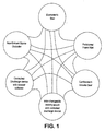
- the invention proposes a number of features, each novel and advantageous in itself.
- the features may be used in an ostomy appliance either in isolation or in combination, to achieve different effects.
- the features include one or more of:
- a first aspect of the invention may provide a sealing member at least a portion of which is elastomeric.
- the sealing member may be configured for sealing around or against a stoma.
- the sealing member may have a closed loop shape.
- the sealing member (or at least the elastomeric portion) may be substantially non-moldable (for example, meaning that it cannot easily be reshaped plastically by manual deformation).
- a substantially non-moldable sealing member is preferred to reduce the possibility that the sealing member may lose sealing force or integrity by substantial plastic deformation (for example, when body waste is pressed against the sealing member for an extended period or at high pressure).
- the sealing member may be used in combination with an adhesive wafer for securing an ostomy appliance to the wearer's skin.
- the sealing member may be configured to seal a periphery of a stomal aperture in the adhesive wafer.
- the sealing member may at least partly overlap the adhesive at the stomal aperture of the wafer, and/or the sealing member may be received at least partly in a gap between the adhesive and the stoma.
- the sealing member may protect the adhesive wafer from exposure to stomal discharge and/or prevent (or at least obstruct) leakage of stomal discharge between the adhesive and the skin. Such protection may be especially advantageous for an ostomy appliance to be worn for an extended period of time, or to be subjected to stomal discharge at high pressure (for example, a controlled discharge device).
- the sealing member may be configured to contact the body to form a seal against the body.
- the sealing member may be configured to contact a portion of the stoma and/or to contact skin around the stoma (e.g., peristomal skin).
- the sealing member may be configured not to contact the stoma.
- the sealing member may be configured to contact the stoma.
- the sealing member may of an impermeable material and/or have an impermeable surface.
- the sealing member may be in the form of a gasket for at least partly overlapping the stoma.
- the sealing member may be configured to apply sealing pressure to the stoma at least partly in an axial direction (for example, at least partly in a direction perpendicular to the skin surface).
- the sealing member may preferably have a stoma engaging surface with a generally closed-loop concave configuration.
- concave may be used broadly to mean that the stoma engaging surface is dished or has a taper or flare such that the sealing member may at least partly cup the surface of the stoma.
- the sealing member may be profiled to have the concave configuration as its natural shape, or the sealing member may have a different natural shape and deform in use to adopt the concave configuration.
- the stoma engaging portion of the sealing member may be flat or planar in an unstressed condition, but deform to provide the concave configuration when fitted to or around the stoma.
- the stoma engaging surface may be configured to engage up to about one third of the height (or protruding height) of the stoma, in use.
- the sealing member may be shaped or supported to apply sealing pressure to the peristomal skin around the stoma.
- a greater sealing force may be applied peristomally than could be applied to the stoma, without the same problems of comfort and stoma damage.
- Such peristomal pressure can improve the seal performance, for example, by one or more of: increasing the area against which the seal can be made; and application of a sealing force to the peristomal skin surrounding the stoma.
- the applied pressure may also tend to at partly increase the degree of protuberance of the stoma, at least relative to the region of skin to which pressure is applied.
- sealing member includes a stoma contacting surface
- increasing the protuberance of the stoma can provide greater stoma area to be contacted (e.g., cupped) by the sealing member and can also urge the stoma outwardly into engagement with the stoma contacting surface of the sealing member.
- Means may be provided for directly or indirectly applying pressure to the sealing member to urge the sealing member against the stoma and/or peristomal skin.
- pressure applying means may, for example, comprise one or more of: a convex shape defining member; a resilient pressure applying member; an inflatable (or pre-inflated) member; a resiliently compressible material, such as foam.
- the pressure applying means may apply pressure directly or indirectly to a surface of the sealing member facing away from the skin.
- the sealing member can also be configured or supported so as to apply greater sealing force around the outside of the stoma (e.g., peristomally) than to the stoma surface itself. This may help protect the stoma from excessive force, while still allowing a high sealing force to be used peristomally.
- another portion of the ostomy appliance may be configured for applying pressure to the peristomal skin around the stoma.
- the seal member may still benefit from the above described effects of increasing stoma protuberance.
- the elastomeric portion of the sealing member may be made of any suitable material, for example, natural or synthetic rubber, silicone, or foam. Such materials may provide excellent cushioning properties (e.g., for comfort), at the same time as excellent elastomeric conformity (e.g., to achieve a closely fitting seal).
- the sealing member may be of a composite construction, comprising first and second materials.
- a first material may provide an impermeable elastomeric sealing surface for contacting with the peristomal skin and/or stoma, to prevent leakage of stomal discharge.
- a second material may provide a foam ring, for example, of open cell foam. The foam material may obstruct release of solid and liquid discharge, but permit escape of flatus gas.
- the foam material may have one or more properties of the peristomal foam wall described below.
- the first and second materials may form a unitary seal member, or the first and second materials may be separable elements.
- the sealing member may be used in a conventional ostomy faceplate for sealing around the stoma, for example, to prevent waste matter from contacting the peristomal skin or from eroding an adhesive attaching the appliance to the skin.
- the excellent sealing performance of the elastomeric sealing member may also be especially suitable for use in a controlled discharge ostomy appliance for controlling or restricting discharge from the stoma.
- the controlled discharge device is a non-entrant device which does not enter the stoma.
- the sealing member can provide significant advantages in achieving a high integrity seal around the stoma to prevent leakage when the device acts to prevent or restrict stomal discharge.
- a second aspect of the invention provides a stoma occluder that acts externally, without entering the stoma itself.
- the stoma occluder may, for example, be implemented as a membrane or drape at least partly covering the stoma.
- the membrane or drape may be formed by a sheet.
- the stoma occluder may be implemented as a block, pad or wad of material.
- the stoma occluder may be pressed against the stoma, for providing a sealing force for occluding the stoma externally.
- the stoma occluder may be implemented as, or supported by, an inflatable or inflated device.
- the term "inflatable/inflated” may be used broadly to mean any device that can be/is expanded, supported or extended by fluid pressure.
- the inflatable/inflated device may be inflated using any suitable inflation fluid, for example, a liquid (e.g., saline) or gas (e.g., air).
- the stoma occluder may be pressed against the stoma by the pressure of inflation.
- the stoma occluder as an inflatable member has an advantage that the fluid can provide a substantially uniform application of pressure as the occluder adapts to the shape of the stoma, regardless of the stoma shape or nonuniformities in the stoma shape.
- the inflatable device may include an inflation port through which the device is inflated. Additionally or alternatively, the inflatable device may be pre-inflated (for example, during manufacture or packaging) and supplied to a user as a ready-inflated item.
- the inflation pressure may be regulated by a feature of the appliance that determines the volume of the inflatable device.
- the feature may be the distance between the stoma and a support surface of the appliance that supports or contacts the inflatable device. The distance may be controlled by one or more spacers, or by a height adjusting mechanism, or a characteristic dimension of the appliance.
- a plurality of appliances may be provided having different characteristic dimensions, to provide different inflation pressures.
- An ostomate may select or be prescribed a specific appliance to suit his or her stoma.
- the stoma occluder may be implemented as, or supported by, an elastomeric member.
- the occluder may be of, or supported by, a resiliently compressible material, such as foam.
- Soft foam can provide excellent elastomeric conformity to adapt to the shape of an individual's stoma and, at the same time, provide excellent cushioning properties for a comfortable fit.
- a hybrid occluder including both an inflatable/inflated device and a foam member is also envisaged.
- the stoma occluder may be impermeable, partly permeable, or substantially permeable, depending on the desired barrier properties for solid waste (stool), liquid waste and gas waste components.
- the stoma occluder may have a generally planar surface, or it may be profiled to fit (either approximately or exactly) a stoma.
- the stoma occluder is especially, but not exclusively, suitable for a controlled discharge device ostomy appliance.
- a third aspect of the present invention provides a wall extending peristomally, and comprising foam.
- the wall is of a closed-loop configuration.
- the wall may define at least partly a confinement region for confining any solid waste excreted from the stoma.
- the wall may be made of or comprise foam material.
- the wall may comprise open cell foam for permitting flatus to vent therethrough.
- the open cell foam may act as a separator for separating flatus gas from solid and/or semi-solid and/or liquid body waste.
- Solid body waste may generally not be able to pass through the foam.
- Liquid and/or semi-solid waste may soak into the foam, but may in general be obstructed in passing through the foam cells by the surface tension of the liquid.
- the wall may be of resiliently compressible foam.
- the foam may be compressed, for producing a tight seal between first and second separable parts of the appliance.
- the compressed foam is able to ensure a strong seal around the confinement region.
- compression of resilient foam may be used to apply a force to a sealing member.
- the sealing member may be configured for sealing around or against the stoma, and/or for sealing an inner periphery in a stomal aperture of the appliance.
- the sealing member may be the elastomeric foam seal described hereinbefore.
- the compressed foam wall may apply pressure directly or indirectly to at least a peristomal region of the sealing member.
- the foam wall may be unitary with the sealing member, or the two may be separate or separable elements.
- the wall may be secured to at least one of a faceplate and a cover.
- the wall may be especially suitable for use in a controlled discharge device for controlling or at least obstructing the discharge of body waste from the stoma.
- the wall may be especially advantageous in combination with one or more of: the elastomeric stoma seal; the non-entrant stoma occluder; and a confinement volume seal described below.
- a fourth aspect of the invention provides a seal for defining at least partly a confinement volume, for example, in a controlled discharge device.
- the confinement volume is a volume external to the stoma, within which stomal discharge (other than flatus) may be substantially confined. Flatus may be vented.
- the confinement volume seal may be effective between a first portion of the appliance that is releasably mounted with respect to a second portion of the appliance.
- the confinement seal may at least partly define the confinement volume when the first portion is mounted with respect to the second portion.
- the confinement volume seal may be broken by releasing the first portion from the second portion.
- the confinement volume seal may be formed at least partly by, or include, one or more of the elastomeric sealing member, the foam wall, and the non-entrant stoma occluder. Additionally or alternatively, a closed loop (e.g. toroidal) confinement member may be provided for applying pressure in a direction towards the skin.
- the confinement member may be configured not to apply pressure to the stoma. Instead, the confinement member may be configured to apply pressure to the foam wall and/or the elastomeric sealing member, to increase the sealing effect surrounding the stoma.
- the confinement member may be an inflatable or inflated member.
- the term "inflatable/inflated” may be used broadly to mean any device that can be/is expanded, supported or extended by fluid pressure.
- the confinement member may include an inflation port through which the device is inflated. Additionally or alternatively, the confinement device may be pre-inflated (for example, during manufacture or packaging) and supplied to a user as a ready-inflated item.
- the inflation pressure may be regulated by a feature of the appliance that determines the volume of the confinement member.
- the feature may be the distance between a surface against which the confinement members bears, and a support surface of the appliance that supports the confinement member.
- the distance may be controlled by one or more spacers, or by a height adjusting mechanism, or a characteristic dimension of the appliance.
- a plurality of appliances may be provided having different characteristic dimensions, to provide different inflation pressures.
- An ostomate may select or be prescribed a specific appliance to suit his or her stoma.
- the confinement member may comprise an elastomeric material to provide a sealing pressure.
- the confinement member could be a composite construction including a spring element (e.g. of metal or plastics) enclosed by an impermeable material.
- a foam wall ring may be arranged between the confinement member and the peristomal skin.
- the foam wall ring may have one or more properties of the peristomal foam wall described above.
- the foam material may be compressed by the pressure applied by the confinement member.
- the properties of the foam and the amount of compression may be configured to prevent escape of solid and liquid components of stomal discharge, while allow flatus gas to escape through the foam.
- an elastomeric sealing member may be arranged for sealing around and/or against the stoma.
- the elastomeric sealing member may have one or more properties of the elastomeric sealing member described above.
- the elastomeric sealing member may be a resilient, conformable member that may create a seal against or around the base of the stoma, to prevent exposure of an adhesive wafer to stomal discharge.
- a fifth aspect of the invention generally provides a universal adhesive faceplate comprising a coupling means for mounting selectively either an ostomy pouch, or a controlled discharge device, to the universal faceplate.
- the controller discharge device may be non-entrant, such that the controlled discharge device does not enter the stoma.
- the coupling means on the faceplate may be configured to permit releasable attachment of the ostomy pouch or controlled discharge device to the faceplate.
- the faceplate may remain in situ on the wearer's skin while one device is interchanged for the other. This can allow an ostomate to swap between an ostomy pouch and a controlled discharge device without having to replace an adhesive faceplate. The inconvenience of removing an existing adhesive faceplate, and applying a new adhesive faceplate unnecessarily, can therefore be avoided.
- a sixth aspect of the invention generally provides a controlled discharge device which incorporates a stowed collector for collecting stomal discharge.
- the controlled discharge device may comprise a first member, a second member releasably secured (or securable) to the first member, and a collapsible collector coupled between the first and second members.
- the collector In an operative (secured) position of the first and second members for preventing (or at least limiting) stomal discharge, the collector may be collapsed to a stowed condition in which the collector occupies only a small volume.
- the collector may be collapsed accordion-style, or folded on itself. The collapsed collector may be stowed within the appliance.
- the collector When the second member is released from the first member, the collector may be distended, to define a larger collection volume for collecting exudate from the stoma. This permits body waste to be discharged when desired by the ostomate, and collected hygienically without having to interchange a collection pouch for the controlled discharge device in order to collect body waste discharged immediately following unblocking of the stoma.
- Embodiments 1 to 8 illustrate preferred configurations of an ostomy appliance comprising a faceplate employing a foam sealing gasket.
- the faceplate may be a mounting device for a waste collection pouch and/or a controlled discharge device.
- the faceplate may be part of a one-piece appliance or part of a multiple-piece appliance (e.g., comprising multiple, separable parts).
- Embodiments 9 to 22 illustrate preferred configurations of a controlled ostomy discharge device.
- the discharge devices may include any of the faceplate configurations of embodiments 1 to 8.
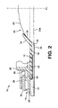
- an ostomy faceplate 10 may generally comprise an adhesive member (or wafer) 12 for securing an ostomy appliance to the skin 20 around a stoma 22.
- the adhesive member 12 may be of closed loop (for example, circular) shape, and comprise a skin-friendly medical grade adhesive, for example, hydrocolloid based adhesive.
- the adhesive surface of the adhesive member 12 may initially be covered by a protective release sheet (not shown) that is peeled from the adhesive member 12 prior to use.
- the appliance is of a two-piece type including a coupling for releasably securing the appliance to the faceplate 10.
- the releasable coupling comprises one or more plastics moldings 14, 16 for forming a mechanical interlock with a complementary coupling member (not shown) on the appliance. If the appliance comprises a collection pouch, then the complementary coupling member may be mounted on the collection pouch. If the appliance comprises a cap, then the complementary coupling member may be mounted on the cap.
- a first of the plastics moldings 14 may be of closed loop shape, and may generally comprise a flange 24 from which upstand one or more walls 26 for guiding engagement with the complementary coupling member (not shown).
- the second plastics molding 16 may generally comprise a split locking ring carried on the first plastics molding 14.
- the split locking ring may comprise a plurality of locking tabs 28 projecting through apertures 30 in one of the walls 26.
- the faceplate 10 further comprises a stoma sealing member 18 for sealing around the periphery of the stoma 22.
- the sealing member 18 may be of closed loop shape, and may generally take the form of a thin gasket comprising a support portion 32 and a stoma engaging portion 34.
- the support portion 32 may be radially outside, and integral with, the stoma engaging portion 34.
- the support portion 32 may be generally planar, and may be received in a recess formed in the adhesive member 12, so as to be sandwiched between the adhesive member 12 and one of the plastics moldings 14.
- the support portion 32 may be secured in position by any suitable means, for example, by welding or by adhesive.
- the stoma engaging portion 34 may be configured to overlap the stoma 22 for sealing against the stoma 22.
- the stoma engaging portion 34 may have a stoma contacting surface 36 of a generally closed loop, concave configuration, surrounding an opening 38.
- the concave configuration may be generally curved in an axial direction (e.g. flared or dished), or generally straight in an axial direction (e.g. frusto conical).
- the concave configuration enables the stoma contacting surface 36 to at least partly cup the surface of the stoma 22.
- Such a concave or cupped contact can provide a relatively large sealing area, especially in contrast to a convex sealing member that arcs away from the stoma surface.
- the stoma engaging portion 34 may be profiled to have the concave configuration as its natural shape, or it may be deformable to the concave configuration when the appliance (or more particularly the sealing member 18) is fitted around the stoma.
- the stoma engaging portion 34 may have a natural flat configuration, and deform to the concave configuration in use.
- the sealing member 18 may be generally elastomeric, and substantially non-moldable (e.g., the sealing member is not easily plastically reshapable in normal use).
- the stoma contacting surface 36 of the sealing member 18 may bear against the stoma 22, at least partly in an axial direction (e.g., at least partly generally perpendicular to the skin surface).
- the sealing member 18 may exert a sealing force on the stoma 22 resulting from one or both of: the at least partly axial pressure; and hoop stress in the sealing member 18 created by slight expansion of the opening 38 to accommodate the girth of the stoma 22 as the sealing member 18 is pressed further down the tapered or rounded side of the stoma 22.
- the sealing member 18 may, for example, be made of plastics foam or a low durometer elastomer such as Silicone or Urethane. These materials may provide excellent cushioning properties (e.g., for comfort), and excellent elastomeric conformity (e.g., to achieve a closely fitting seal).
- the sealing member 18 is preferably impermeable, and may be of closed cell foam, or of open cell foam having an impermeable surface or skin.
- the sealing member may also be of a composite structure with an impermeable bottom surface and an open cell upper element.
- the sealing member 18 may be less than about 2 mm in thickness, for example, about lmm thick. However, sealing members greater than 1 or 2 mm in thickness may be used as well.
- Composite sealing members consisting of two or more materials may be 10mm-13mm or more in thickness.
- a small clearance 40 is shown under the sealing member 18, resulting from the step shape of the adhesive member 12 for accommodating the sealing member 18. If desired, the clearance 40 may be filled, for example, by profiling the sealing member 18 to have a complementary step shape.
- the ostomate may cut the stomal aperture 38 of the sealing member 18 to a size to match his or her stoma 22. This can provide a custom fit, and may be especially useful for irregular stoma shapes.
- the faceplate 10 may be supplied with a pre-sized sealing member 18.
- the sealing member 18 seals the gap between the edge of the adhesive member 12 and the soma 22, to prevent body waste from contacting, and potentially leaking under, the adhesive member 12.
- the adhesive member 12 may erode if contacted by body waste, and the adhesive bond to the skin 20 may also be weakened or lose integrity.
- the resilience of the sealing member 18 can ensure a comfortable, yet snug fit around the stoma, and provide a reliable seal against waste egress.
- the concave configuration of the stoma contacting portion 34 provides a large sealing area.
- the faceplate 10 of the second embodiment is very similar to the first embodiment except for the positioning of the sealing member 18.
- the adhesive member 12 is not step-shaped.
- the sealing member 18 fits between the upper surface of the adhesive member 12 and an undercut lug 42.
- the lug 42 may have a continuous annular shape, or may comprise angularly spaced lug segments.
- An adhesive for example, a low tack adhesive 44 may be coated on the underside of the sealing member 18 to secure the sealing member to the adhesive member 12.
- the adhesive 44 may also be coated over the stoma contacting surface 36 of the sealing member 18 to adhere the sealing member 18 to the stoma 22.
- An adhesive bond between the sealing member 18 and the stoma 22 may further improve the seal between the sealing member 18 and the stoma 22.
- the sealing member 18 of the second embodiment is located slightly further from the skin 20 than in first embodiment. In case this results in a smaller stoma contacting surface 36, the adhesive 44 may compensate for the reduced sealing area.
- the sealing member 18 may be fitted either during manufacture of the faceplate 10, or just prior to use by the ostomate. If desired, the stomal aperture of the adhesive member 12 and/or of the sealing member 18 may be trimmed to a size to match the stoma 22 just prior to securing the faceplate to the ostomate's skin 20. Additionally, or alternatively, the ostomate may have the facility to select a pre-sized sealing member 18 from a range of sealing member sizes.
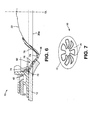
- the faceplate 10 of the third embodiment is similar to that of the preceding embodiments, except that an additional shape defining member 50 is provided.
- the shape defining member 50 is shaped to define a convex bulge 51 to apply pressure to the skin 20 peristomally.
- the shape defining member 50 is preferably relatively stiff at least compared to the sealing member 18.
- the shape defining member 50 may be made of any suitable material, such as plastics (for example, polyethylene) or metal (for example, stainless steel).
- the shape defining member 50 may be substantially rigid, or resilient.
- the shape defining member 50 comprises a spring, in the form of a diaphragm spring having a support portion 52 engaged under the undercut lug 42 (described in the second embodiment), and a convex tapered (e.g. conical) portion 54.
- a spring is preferred to be able to adapt to different individual's stomas 22, and to provide a degree of cushioning for a comfortable fit.
- the convex conical portion 54 bears partly on an inner peripheral portion 58 of the adhesive member 12, and partly on a peristomal portion 60 of the sealing member 18.
- the sealing member 18 may be fastened to the adhesive member 12 and/or to the shape defining member 50, or the sealing member 18 may be separate but held captive against the skin 20 by the shape defining member 18. Although not shown, the sealing member 18 may also extend further outwardly to be sandwiched between the adhesive member 12 and the shape defining member 50.
- the shape defining member 50 of this embodiment does not bear directly against the stoma 22, and so the shape defining member 50 may be relatively stiff (at least compared to the sealing member 18).
- the shape defining member 50 serves to apply pressure to the skin 20 immediately adjacent to the stoma 22. This may offer one or more of the following advantages:
- the shape defining member 50 and/or the sealing member 18 may be fitted to the faceplate 10 during manufacture, or one or both may be fitted manually by the ostomate just prior to securing the faceplate 10 to the ostomate's skin. As in the previous embodiments, the sealing member 18 may be presized, or the ostomate may trim the sealing member 18 to suit his or her stoma.
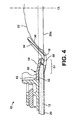
- the fourth embodiment is similar to the third embodiment.
- the main differences relate to the configuration of the shape defining member 50.
- the shape defining member 50 comprises a molded plastics insert having a support portion 62 and a convex projection 64.
- the convex projection 64 may be substantially co-extensive with the adhesive member 12.
- the support portion 62 comprises a latch profile 66 for interlocking engagement with the lug 42 of the faceplate 10.
- the latch profile 66 includes a tapered lead-in surface 68 to enable the shape defining member 50 to be snapped into position.
- the sealing member 18 overlaps, and is sandwiched between, the adhesive member 12 and the convex projection 64 to retain the sealing member 18 in position.
- the shape defining member 50 functions in the same manner as described in the third embodiment, to apply pressure to the peristomal skin 20 surrounding the stoma 22.
- the shape defining member 50 and/or the sealing member 18 may be fitted to the faceplate 10 during manufacture, or one or both may be fitted manually by the ostomate just prior to securing the faceplate 10 to the ostomate's skin.
- the sealing member 18 may be presized, or the ostomate may trim the sealing member 18 to suit his or her stoma.
- the adhesive member 12 may also be cut to size, if desired.
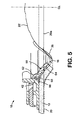
- the fifth embodiment is similar to the third and fourth embodiments.
- the main differences relate to the configuration of the shape defining member 50.
- the shape defining member 50 did not overlie the stoma 22, and did not apply pressure directly to the stoma 22.
- the shape defining member 50 is configured to apply pressure additionally to the stoma 22.
- the shape defining member 50 be at least partly resilient, to allow the sealing member 18 to conform to the shape of the stoma 22.
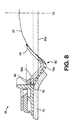
- the shape defining member 50 preferably comprises a rim portion 72 from which project a plurality of inwardly directed spring fingers 74. In the present example, seven fingers 74 are provided substantially equally angularly spaced from each other.
- the number and placement of the fingers may be varied as desired.
- Each spring finger 74 may be substantially V-shaped to provide a first convex portion 76 (similar to the convex portion 54 of the third embodiment), and a second return portion 78.
- the return portion 78 may be shaped to approximately match the concave shape of the stoma engaging portion 34 of the sealing member 18, to press the stoma engaging portion 34 against the stoma 22.
- the apex 79 of the V-shape of the spring finger 74 may be slightly rounded, for reasons of comfort.
- a V-shape is illustrated in Fig. 5, the spring fingers 74 may have any suitable convex or bulged shape to provide pressure against the peristomal skin 20, and additional part-axial and/or part-lateral pressure against the stoma 22.
- the spring fingers 74 can flex independently of one another, to adapt to the shape and size of the individual's stoma 22. For example, flexing of one spring finger 74 does not affect flexing of other spring fingers 74. This can allow the shape defining 50 member to urge the sealing member 18 tightly against the stoma surface, while still allowing a high degree of conformity to suit different stoma shapes and sizes.
- the shape defining member 50 may be held in position by the lug 42 of the faceplate 10.
- the spring member 50 may further comprise a circumferential latch profile 73 with a complementary shape to the lug 42.
- the latch profile 73 may also provide additional strength for reinforcing the rim portion 72. Alternatively, if the latch profile 73 is omitted, then the rim portion 72 may locate under the lug 42 (as in the third embodiment).
- the shape defining member may be made of any suitable material, such as plastics or metal (for example, stainless steel).
- the sealing member 18 may overlap the adhesive member 12 to be sandwiched between the adhesive member 12 and the shape defining member 50.
- the sealing member 18 may be dimensioned to butt the inner peripheral edge of the adhesive member 12, as in the third embodiment.
- the shape defining member 50 and/or the sealing member 18 may be fitted to the faceplate 10 during manufacture, or one or both may be fitted manually by the ostomate just prior to securing the faceplate 10 to the ostomate's skin.
- the sealing member 18 may be presized, or the ostomate may trim the sealing member 18 to suit his or her stoma.
- the sixth embodiment is similar to the fifth embodiment, except that the sealing member 18 and the shape defining member 50 are integrally formed as a unitary member 80, referred to herein as the unitary shape/sealing member 80.
- the unitary shape/sealing member 80 may be of plastics, and formed by integral molding, for example, multi-shot molding.
- integral molding may be used broadly to mean any molding process for integrally forming two different portions as a unitary member, and may rely, for example, on chemical bonding of different plastics materials, or mechanical keying between the two portions, or a combination of both.
- the unitary shape/sealing member 80 comprises a first portion 18a of a first relatively soft elastomeric plastics, and one or more second portions 50a of a second relatively stiff plastics.
- the second portions 50a may be substantially rigid, or stiffly resilient.
- the first portion 18a may be equivalent to the sealing member 18 of the preceding embodiments.
- the one or more second portions 50a may serve to stiffen the first portion 18a in a similar manner to the shape defining member 50 of the third, fourth and fifth embodiments.
- a plurality of second portions 50a are provided in the form of ribs.
- the ribs 50a may define a convex profile in a peristomal region of the first portion 18a.
- the ribs 50a may also be shaped to apply pressure, at least partly against the stoma 22. It is preferred that the first portion 18a extend further inward than the second portions 50a.
- the second portions 50a may be independent (e.g., unconnected directly to one another). This can permit the unitary shape/sealing member 80 to flex in all directions, and allows the unitary shape/sealing member 80 to adapt to the shape and size of an individual's stoma 22.
- the second portions 50a may be molded with a latch profile 82 for forming a mechanical interlock with the rib 42 of the faceplate 10, to hold the unitary shape/sealing member 80 in position.
- the unitary shape/sealing member 80 may be fitted to the faceplate 10 either during manufacture, or it may be fitted by the ostomate just prior to adhering the faceplate 10 to the skin 20. If desired, the ostomate may trim the inner periphery of the first portion 18a to suit his or her stoma size.
- the seventh embodiment is similar to the third to sixth embodiments.
- the main differences relate to the configuration of the shape defining member 50 and the adhesive member 12.
- the adhesive member 12 may include a first zone 12a supported by the shape defining member 50 to have a well defined, bulged shape.
- the adhesive member 12 may include a second zone 12b unsupported by the shape defining member 50, so as to allow at least a degree of moldability.
- the second zone 12b may be shapeable by the ostomate to adapt the adhesive member 12 to suit the individual's stoma size and shape.
- the ostomate can shape the adhesive in the second zone 12b to form a custom fit around and/or against the stoma 22.
- the sealing member 18 may overlap, and be secured to, the adhesive in the second zone 12b.
- the sealing member 18 may be secured by an adhesive surface of the adhesive member 12, or the sealing member may be bonded or welded to the adhesive member 12.
- the sealing member 18 may include an elastomeric concave configuration to cup the surface of the stoma 22.
- the adhesive attachment of the second zone of the adhesive to the stoma 22 provides may provide additional support for the elastomeric sealing member 18.
- the adhesive member 12 may be partly elastic to provide a degree of spring-back, such that the adhesive tends to elastically hug the stoma 22 and/or such elasticity may result from the elastomeric nature of the sealing member 18.
- the eighth embodiment may be similar to the first and second embodiments.
- the main differences relate to the configuration of the sealing member 18.
- the seal member 18 is configured not to directly contact the stoma 22. Instead, the adhesive pad 12 may be cut-back slightly to leave a clearance 84 between an inner edge 12c of the adhesive pad 12 and the stoma 22.
- An inner edge portion 18c of the sealing member 18 may be configured to partly overlap the inner edge of the sealing member 18, and extend into the clearance 84.
- the sealing member 18 therefore protect the inner edge of the adhesive pad from exposure to stomal discharge and/or prevent (or at least obstruct) leakage of stomal discharge between the skin 20 and the adhesive pad 12.
- the sealing member 18 may be located by the undercut 42 and/or by pressure applied from another portion of the appliance in a direction towards the skin.
- a pressure applying member (indicated in phantom at 86) may be arranged on the side (or face) of the sealing member facing away from the skin 20.
- the pressure applying member may comprise an inflatable device and/or a member of compressible foam material.
- the foam material may be of closed cell foam, or of open cell foam, depending on the permeability characteristics desired for solid, liquid and gas body waste.
- the pressure applying member 86 may apply pressure from another portion (not shown) of the ostomy appliance in a direction towards the skin when the other portion is attached to the faceplate 10.
- the other portion may be a collection pouch and/or a controlled discharge device.
- the pressure applying member 86 may at least partly overlie the clearance 84 and/or the inner edge of the adhesive pad 12.
- the pressure applying member 86 does not directly overlie the stoma 22.
- the pressure applying member 86 may be unitary with the sealing member 18 (as a composite member), or the pressure applying member 86 may be separate or separable from the sealing member 18.
- the sealing member 150 and/or the adhesive pad 12 may be pre-sized, or one or both of these elements may be cut to a desired shape and/or size by the ostomate.
- a shape defining member 50/80 of one or more of the preceding embodiments may be used in the eighth embodiment, to further increase the sealing force exerted through the sealing member 18.
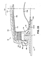
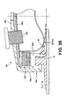
- the ninth embodiment relates to a controlled discharge device 90 which may include the faceplate 10 and elastomeric sealing member 18 of any of the preceding embodiments.
- the sealing member 18 is depicted schematically to have a peristomal bulge 18a, and a stoma contacting surface, but it will be appreciated that the specific shape and configuration of the sealing member 18 and/or the shape defining member 50/80 (if provided), and the adhesive member 12, may vary, for example, as illustrated in the preceding embodiments.
- the controlled discharge device may further comprise a non-entrant stoma occluder 92 in the form of an inflatable balloon 94.
- the balloon 94 may be inflated using any suitable inflation fluid, for example, a liquid (such as saline) or a gas (such as air).
- the inflation fluid may be supplied through an inflation port or conduit 96 from a pump (not shown).
- An inflation/deflation valve (not shown) may also be provided.
- the balloon 94 may be supported in a cap 98 secured permanently or releasably to the faceplate 10, for example, via the plastics moldings 14 and 16.
- the balloon 94 may be of an elastic material, or of a non-elastic material.
- a stoma occluding surface 100 of the balloon 94 may be urged against the stoma 22.
- the stoma occluding surface 100 may drape over the stoma 22, and also over the stoma engaging portion 34 of the elastomeric sealing member 18.
- the stoma occluding surface 100 may be profiled (e.g. pleated or constrained, or molded) to have a non-planar shape.
- the stoma occluding surface may have a natural concave shape generally to complement the shape of the stoma 22.
- the stoma occluding surface 100 may have a natural planar shape which may crease and/or fold as the stoma occluding surface 100 is pressed against the projecting stoma 22, to adapt to the projecting shape.
- a waste collector 102 may be incorporated into the appliance.
- the collector 102 may be collapsible, for example, as a bellows.
- the collector 102 may be in the form of a sleeve or tube that is attached to the cap 98 radially outside the stoma occluder 92.
- the cap 98 may consist of a lower coupling part 98a (first member) for coupling to the faceplate 10, and an upper cover part 98b (second member) for covering the lower part 98a.
- the upper and lower parts 98a and 98 may be releasably fastened, or fastenable, together.
- a releasable fastening 98c may be used for fastening the upper and lower parts 98a and 98 together.
- the releasable fastening 98c may be refastenable after release, or it may be a one-time release device.
- the collector 102 may extend between the two cap parts 98a and 98b.
- the collector 102 may be collapsible into a stowed condition (illustrated in Fig. 10) when the lower and upper parts 98a and 98b of the cap 98 are secured together.
- the collector 102 defines a collection volume 104 around the occluder 92.
- One or more flatus vents 106 may be provided in the cap 98 or in the wall of the collector 102 to allow flatus to vent from the collection volume 104.
- Each flatus vent 106 may include a deodorising filter (not shown).
- the deodorizing filter may be a conventional deodorizing filter commonly used in ostomy pouches.
- the lower and upper parts 98a and 98b of the cap are fastened together, and the cap 98 is secured to the faceplate 10.
- the balloon 94 is inflated to occlude the stoma 22 (as depicted in Fig. 10).
- the pressure in the balloon 94 may generally be sufficient to obstruct egress of solid, semi-solid and liquid waste from the stoma 22.
- Flatus gas may have sufficient pressure to lift the stoma engaging surface 100 of the balloon 94 partly away from the stoma 22, and to create small, temporary channels under the stoma engaging surface 100 to allow the flatus to escape to the surrounding collection volume 104. From the collection volume 104, the flatus may vent to the surrounding atmosphere via the one or more flatus vents 106.
- the elastomeric sealing member 18 provides a precautionary seal around the stoma 22 in case any solid, semi-solid or liquid waste should leak from the stoma 22 past the stoma occluder 92. Leakage of waste might occur due to a pressure drop inside the balloon 94, for example, should any of the inflation fluid leak or should the balloon volume increase to accommodate a change in distance between the balloon 94 and the stoma 22. Also, when the appliance 10 is worn for long periods of time, liquid or semi-solid waste may leak with the passing of flatus. In such a case, it may be important to prevent the body waste from contacting the adhesive member 12. Body waste may erode the adhesive member 12 (leading to possible adhesive failure), or the body waste may leak out between the adhesive member 12 and the skin.
- the environment within a controlled discharge device may be completely different from that in a normal ostomy pouch.
- waste is permitted to flow substantially unobstructed from the stoma into the pouch. Therefore, a conventional stoma seal for an ostomy pouch does not have to withstand considerable pressure of waste acting on the seal.
- any body waste leaking under the balloon 94 is confined to the collapsed collection volume 104 defined by the collapsed collector 102. The body waste may therefore be under considerable pressure.
- the elastomeric sealing member 18 can provide a strong seal around the stoma 22 to prevent any such leaked waste matter from reaching the adhesive member 12.
- the shape of the elastomeric sealing member 18 may utilize the pressure to increase the sealing force against, or around, the stoma 22.
- pressure acting on the surface of the sealing member 18 facing away from the stoma 22 and/or the peristomal skin may increase the sealing force on, or around, the stoma 22, to provide a stronger seal. Therefore, the elastomeric sealing member 18 may enable a more durable seal to be obtained than conventional stoma seals (e.g., typically used for ostomy pouches) that may not provide sufficient seal strength for an externally acting controlled discharge device.
- the balloon 94 may optionally be deflated, and the upper cap part 98b may be released from lower cap part 98a. This extends (or at least permits extension of) the collector 102, to expand the collection volume 104. Since the stoma occluder 92 does not now occlude the stoma 22, body waste is able to be discharged freely from the stoma 22 into the collector 102. The collector 102 therefore provides for hygienic discharge of waste after the stoma 22 has been occluded for a period of time. Once the discharge has been completed, the lower cap part 98a may be released from the faceplate 10 for disposal, and a fresh cap assembly 98 fitted to the faceplate 10.
- the present embodiment enables the faceplate 10 to remain in position for use with replaceable cap assemblies 98
- other embodiments may be configured for disposal of the faceplate 10 with the collector 102 and the cap assembly 98 (in a similar manner to a one-piece ostomy pouch).
- the lower cap part 98a may be permanently secured to the faceplate 10, or the lower cap part 98a may be omitted (and the collector 102 sealed directly to the upper cap part 98a and the faceplate 10).
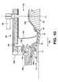
- the tenth embodiment is very similar to the ninth embodiment.
- the main difference is the provision of a layer 108 of compressible foam extending at least in front of the stoma occluding surface 100 of the balloon 94.
- the foam layer 108 may provide one or more of the following functions:
- the foam layer 108 may be left unskinned, or it may be provided with a gas permeable skin (not shown). If the foam layer is intended to be impermeable to gas, then a non-permeable skin (not shown) may be used and/or the foam wall 108 may be of closed cell foam.
- the eleventh embodiment is very similar to the ninth embodiment.
- the main difference is the provision of a foam wall 110 around the stoma 22.
- the foam wall 110 may have a generally closed loop shape, for example, annular.
- the foam wall 110 may provide one or more of the following effects:
- the foam wall 110 may be arranged to be radially inside any flatus vents 106 in the cap 98 and/or in the wall of the collector 102.
- the foam wall 110 can provide a degree of protection against leakage of liquid or semi-liquid waste through the flatus vents 106 (and also prevent soiling of any deodorizing filters, if present).
- the foam wall 110 may be secured to one or both of the faceplate 10 and the cap 98.
- the foam wall 110 may be secured permanently or releasably.
- the foam wall 110 may be provided with an inwardly extending lip 110a.
- the lip 110a may permit transfer of the axial sealing force from the internal pressure of the balloon 94, to increase the axial force exerted by the foam wall 110 in the faceplate region 112.
- the collector 102 may be omitted. Instead, the foam wall 110 may provide a reliable barrier to solid, semi-solid and liquid waste leakage. Any accumulated body waste 98 may need to be cleaned if or when the cap 98 is released from the faceplate 10.
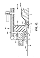
- the twelfth embodiment is very similar to the eleventh embodiment.
- the main difference is that the foam wall 110 is part of a foam member 120 that includes a portion 122 extending behind the inflatable balloon 94.
- the portion 122 may act as a compressible spring between the cap 98 and the balloon 94 to urge the balloon 94 against the stoma 22. Urging the balloon 94 against the stoma 22 may be advantageous in reducing the volume of the balloon 94, and also reducing the effects of a drop in pressure of the inflation fluid inside the balloon.
- the spring effect of the foam portion 122 may also assist in accommodating changes of distance between the stoma 22 and the cap 98.
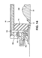
- the thirteenth embodiment is similar to the eleventh embodiment, except that the inflatable balloon 94 (occluder 92) is omitted.
- the foam wall 110 surrounds the stoma 22 (as described in the tenth embodiment) and defines a confinement region 130 for body waste exiting the stoma 22.
- the foam wall 110 acts as at least part of a confinement volume seal for sealing between separable portions of the cap 98.
- the stoma 22 is not directly occluded, but waste matter is confined to the small confinement region 130.
- the foam wall 110 may act as a separator to confine solid waste, and also liquid or semi-solid waste. As explained previously, liquid waste may partly soak into the foam wall 110, but generally does not pass through the foam material. Gas may pass through the foam wall 110 to vent through the flatus vents 106.
- the foam wall may provide one of more of functions (a) - (c) described in the eleventh embodiment.
- Function (a) may be advantageous to enhance the sealing properties of the elastomeric sealing member 18, because sealing member 18 is directly exposed to body waste that is permitted to exude from the stoma 22 until the confinement region 130 becomes filled.
- Function (b) may be advantageous because the occluder 92 of the eleventh embodiment is no longer present to confine solid and liquid waste matter within the stoma 22.
- the foam wall 110 may therefore provide a primary separation function to allow flatus to escape.
- the foam wall 110 may therefore provide a primary seal function to define the confinement volume, for example, relative to the separable parts of the cap 98.
- the upper part 98b of the cap 98 is released from the lower cap part 98a. This extends (or at least permits extension of) the collector 102, to expand the collection volume 104. Body waste accumulated in the confinement region 130 is able to be discharged freely into the collector 102.
- the collector 102 therefore provides for hygienic discharge of waste after the appliance has been used to obstruct stomal discharge for a period of time.
- the cap assembly 98 and the collector 102 may be separated from the faceplate 10 for disposal, and replaced using a fresh cap assembly 98 and collector 102.
- the fourteenth embodiment is very similar to the thirteenth embodiment.
- the main difference is that an absorbent member 132 of or containing absorbent material is provided in the confinement region 130 defined by the foam wall 110.
- the absorbent material may, for example, be a superabsorbent.
- a suitable super absorbent is, for example, an alkali metal methyl methacrylate.
- the absorbent member 132 may be secured to the interior surface of the cap 98, for example, by a heat seal or by adhesive.
- the absorbent member 132 may serve one or both of:
- the absorbent member 132 may tend to expand as it absorbs liquid. Such expansion can increase the degree to which the absorbent member 132 fills or occupies the confinement region 130.
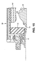
- the fifteenth embodiment is similar to the tenth embodiment, except that the inflatable balloon 94 is replaced by a foam stoma occluder 140.
- the foam stoma occluder 140 may be a separate member from the foam wall 110 (as illustrated in Fig. 16), or the foam stoma occluder 140 and the foam wall 110 may be integrally formed as a unitary member.
- the foam stoma occluder 140 is preferably resilient, and may be of open cell foam and/or of closed cell foam.
- the foam stoma occluder 140 may have a generally planar stoma occluding surface 142, or it may be profiled with a non-planar stoma occluding surface 142.
- the foam stoma occluder 140 may be profiled to have a concave shape generally to match the shape of the stoma 22.
- the foam stoma occluder 142 may be generally hollow, and define an open region 144 behind the stoma occluding surface 142.
- the foam stoma occluder 140 may perform one or both of the following functions:
- the foam may be open-cell foam or closed-cell foam.
- One or both of the surfaces of the foam stoma occluder 140 may be skinned (not shown), and each skin may be permeable or non-permeable.
- the sixteenth embodiment is similar to the fifteenth embodiment.
- the main difference lies in the configuration of the foam stoma occluder 140.
- the foam stoma occluder 140 is a solid member without any open region 144 of the fifteenth embodiment.
- the foam stoma occluder 140 is preferably resilient to conform to the shape of the stoma 22, and to form a close fit thereagainst.
- a flexible membrane or surround 146 may surround at least the stoma occluding surface 142 of the foam stoma occluder 140.
- the flexible surround 146 and/or the foam stoma occluder 140 may be configured to be generally gas permeable or generally impermeable.
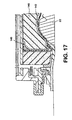
- the seventeenth embodiment is very similar to the fifteenth and sixteenth embodiments.
- the main difference is the configuration of the foam stoma occluder 140.
- a foam stoma occluder is generally solid, and comprises open-cell foam.
- the occluder 140 includes an annular extension flange 148 projecting radially outwardly and received between the lower edge of the foam wall 110, and the region 112 of the faceplate to which pressure is applied.
- the foam wall 110 may be relatively non-compressible or stiffly compressible compared to the foam material of the occluder 140.
- the foam wall 110 may compress the extension flange 148, to apply pressure to the region 112 of the faceplate 10.
- the force applied to the extension flange 148 by the foam wall 110 may tend to urge the foam stoma occluder against the surface of the stoma 22.
- the foam stoma occluder is preferably soft to provide a comfortable fit against the stoma 22.
- the foam stoma occluder 140 may be of open cell foam to allow flatus from the stoma 22 to pass through the occluder 140 and to reach the foam wall 110.
- the foam wall 110 also permits the passage of gas therethrough, allowing the gas to reach the collection volume 104, and to vent through the one or more flatus vents 106.
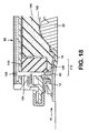
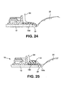
- the eighteenth embodiment is similar to the thirteenth and fourteenth embodiments.
- the stoma 22 is not directly occluded by a contacting surface.
- the appliance may use a faceplate similar to that of the eighth embodiment.
- the confinement region 130 defined by the foam wall 110 may optionally contain an absorbent member 132 to at least partly fill the confinement region and/or to absorb liquid body waste.
- the elastomeric sealing member 18 may take the form of a gasket 150.
- the gasket 150 may be of foam.
- the gasket is preferably non-permeable.
- the gasket 150 may comprise closed-cell foam and/or may include impermeable skinned surfaces.
- the gasket 150 may be separate from the foam wall 110, or the gasket 150 may be joined to, or integrally formed with, the foam wall 110.
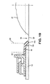
- the gasket 150 may serve to seal an inner peripheral edge 12c of the adhesive member 12 against contact by body waste excreted by the stoma 22 and collecting in the confinement region 130. At least a portion 150a of the gasket 150 may contact the peristomal skin 20. The gasket 150 may partly overlap the edge 12c of the adhesive member 12 (as illustrated in Fig. 19), or the gasket 150 may entirely bear against the peristomal skin 20.
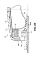
- the nineteenth embodiment is similar to the eighteenth embodiment, except for the configuration of the confinement volume seal.
- the foam wall 110 does not extend the entire height of the cap.
- an inflatable confinement member 160 is disposed on the underside of the cap to bear on the foam wall 110.
- the confinement member 160 may be generally annular or toroidal and, in the example illustrated, has a width approximately equal to that of the foam wall 110.
- the confinement member 160 is configured such that it does not apply a force directly to the stoma 22.
- the elastomeric sealing member is in the form of a gasket 150 that overlaps the inner edge 12c of the adhesive pad 12. A portion 150c of the gasket may bear against the peristomal skin 20.
- the gasket 150 may be configured not to apply a sealing pressure directly to the stoma 22.
- the confinement member 160 may be inflated via an inflation port 96, by means of a suitable pump (not shown).
- the pump may be incorporated into the appliance, or it may be a separate item.
- the inflation pressure within the confinement member 160 determines the strength of the confinement volume seal relative to the parts 98a and 98b of the cap 98, and the force with which the gasket 150 is pressed against the adhesive pad 12 and/or against the peristomal skin 20.
- the pressure may also control the degree to which the foam wall 110 is compressed, which might affect the properties of the foam member 110 in separating flatus while containing solid and liquid stomal discharge.
- the region between the collector 102 and the foam wall 110/confinement member 160 may be vented to allow the escape of flatus that has passed through the foam wall 110.
- a deodorising filter (not shown) may be incorporated to deodorise the flatus.
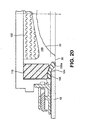
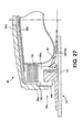
- the twentieth embodiment is very similar to the nineteenth embodiment.
- the main difference lies in the manner in which the confinement member 160 is inflated.
- an inflation port 96 is provided to allow the ostomate to inflate the confinement member 160 to a desired pressure.
- the confinement member is pre-inflated, for example, during manufacture of the ostomy appliance.
- a small port 162 may be provided in the cap 98 to allow for inflation during manufacture.
- the port 162 may be sealed by a plug (not shown) to prevent escape of the inflation fluid.
- the inflation pressure of the confinement member 160 may be predetermined by the manufacturer. This can help avoid differences in performance caused by under- or over-inflation of the confinement member 160 by an ostomate. It also avoids the inconvenience to the ostomate of having to inflate the confinement member 160, and avoids the inconvenience and expense of providing the user with a dedicated inflation pump.
- the volume of the confinement member 160 may generally be fixed by the design of the cap 98.
- the confinement member 160 does not bear against the stoma 22, and so the volume of the confinement member 160 may not be affected by the size and shape of the stoma 22. Since the volume may generally be fixed, then the inflation pressure within the confinement member 160 may be predictable when the appliance is worn on the body. Should adjustment of the inflation pressure be desired, then the pressure may be varied by changing the thickness of the foam member 110 and/or the gasket 150, or some other dimension.
- a range of ostomy appliances may be manufactured with different models inflated to different inflation pressures. The ostomate may select (or be prescribed) a respective model having an inflation pressure to suit his or her personal characteristics.
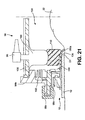
- the twenty first embodiment is very similar to the eighth embodiment.
- One difference lies in the manner in which the inflatable balloon 94 is inflated.
- an inflation port 96 is provided to allow the ostomate to inflate the inflatable balloon 94 to a desired pressure.
- the inflatable balloon 94 is pre-inflated, for example, during manufacture of the ostomy appliance.
- a small port may be provided in the cap 98 to allow for inflation during manufacture. The port may be sealed by a plug (not shown) to prevent escape of the inflation fluid.
- pre-inflation of the balloon 94 provides advantages in simplicity and convenience of use, and avoids the need for the user or the appliance to carry a dedicated inflation pump.
- the balloon 94 may be configured to contact the stoma 22.
- the shape and volume of the balloon 94 may therefore vary in use, depending on the shape and size of the individual's stoma 22. Such variations in volume may affect the pressure within the balloon 94, and hence affect the seal pressure of the balloon 94 against the stoma 22.
- a range of appliances may be produced having different initial inflation pressures.
- the ostomate may select (or be prescribed) a model having a particular initial inflation pressure to suit his or her stoma.
- the volume of the balloon 94 may be controlled by a characteristic of the cap 98.
- the characteristic may a distance between the faceplate 10 (or the first part 98a of the cap 98), and a rear surface (98b/98d) on which the balloon 94 is supported. This distance may be controlled by a dimension of the cap 98.
- a range of caps 98 may be produced having different characteristic dimensions for controlling the volume of the balloon 94, and the ostomate may select (or be prescribed) a suitable model for his or her stoma.
- the balloon 94 is supported by the second cap part 98b that is coupled to the collector 102.
- the second cap part 98b is coupled to an outer cap cover 98d to depend from the cover 98d.
- the cover 98d has a skirt or sidewall 98e that extends towards the faceplate 10, and is releasably secured to the first cap part 98a by the releasable connection 98c.
- the releasable connection 98c is a mechanical catch.
- the height of the sidewall 98e may determine the "height" of the second cap part 98 above the faceplate 10, and hence can control the extent to which the balloon 94 is pressed against the stoma 22.
- a range of outer covers 98d having different sidewall heights 98e may be produced.
- An ostomate may choose (or be prescribed) an appliance having a particular sidewall height to suit his or her stoma.
- the cap 98 may include an adjustment mechanism for adjusting the height of the second cap part 98b relative to the faceplate 10.
- an adjustment mechanism may adjust the position of the second cap part 98b relative to the outer cap cover 98d, and/or the position of the outer cap cover 98d relative to the first cap part 98a.
- a threaded or ramp connection may be used to control axial displacement according to a rotational position. A threaded example is illustrated in Embodiment 23.
- one or more spacers may be provided for adjustment of the relative positioning of the balloon 94 or surfaces abutting or supporting the balloon 94.
- the thickness (e.g. height) of the sealing member 18 may be varied to affect the volume of the balloon 94 and hence affect the inflation pressure of the balloon 94.
- a range of sealing members of different thickness, and/or a range of foam walls of different thickness may be provided to allow an ostomate to select a suitable size to suit his or her stoma.
- Such sealing members or foam wall ranges may either be pre-installed in a range of different caps 98, or they may be installable by the ostomate in a standard cap 98 to customise the cap 98 to suit his or her stoma.
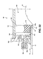
- Flatus may vent from the region 104 between the balloon 94 and the collector 102 by passing through one or more vent channels 170 between the second cap part 98b and the outer cap cover 98d.
- the channels may, for example, be defined by one or more contours of the upper surface of the second cap part 98b and/or the lower surface of the outer cap cover 98d.
- the channels 170 may be generally narrow in at least one dimension to obstruct the passage of solid stomal discharge in the channels 170.
- a deodorising filter 172 may be provided at a vent aperture 174 of the cap 98, in communication with the channels 170, such that flatus venting from the cap 98 passes through the deodorising filter 172 in order to pass to the outside environment.
- the balloon 94 may have a contoured profile, including a peripheral annular projecting portion 100a and central recess or depression 100b contoured to an approximate shape of a stoma.
- the twenty second embodiment is very similar to the twenty first embodiment.
- the main difference lies in the implementation of the sidewall 98e for the outer cap cover 98d, and of the releasable connection 98c to the first cap part 98a.
- the sidewall 98e and the releasable connection 98c may be formed by an annular spacer or segment 98f that is arranged between an upper part of the outer cap cover 98d, and the first cap part 98a.
- the annular segment 98f may include a releasable connection (for example, a frangible connection) to one or both of the outer cap cover 98d or the first cap part 98a.
- the length (or "height") of the annular segment 98f may determine the height of the outer cap cover 98d and the second cap part 98b relative to the first cap part 98a, and hence may control the volume of the balloon 94.
- the ostomate When the ostomate desires to discharge from the stoma, the ostomate releases the outer cover part 98d, which removes the balloon 94 from sealing engagement, and allows distention of the collector 102.
- the twenty third embodiment is similar to the twenty first embodiment.
- the main difference lies in the implementation of the releasable connection 98c between the outer cap cover 98d and the first cap part 98a.
- a screw threaded connection is formed between a first screw thread 180 on the first cap part 98a, and a second screw thread 182 on the side wall 98e of the outer cap cover 98d.
- An ostomate can adjust the volume (and hence pressure) of the balloon 94 by rotation of the outer cap cover 98d relative to the first cap part 98a. Rotation in one direction (e.g.
- the ostomate When the ostomate desires to discharge from the stoma, the ostomate completely unscrews the outer cap cover 98d to separate the outer cap cover 98d from the first cap part 98a.
- the second cap part 98b may be secured to the outer cap cover 98d for rotation therewith.
- the outer cap cover 98d may be rotatable relative to the second cap part 98b.
- the second cap part 98b may remain in a fixed rotational orientation with respect to the first cap part 98a.
- the threaded connection may be between the outer cap cover 98d and the second cap part 98b. Rotation of the outer cap cover 98d may then generate relative movement of the second cap part 98b either towards or away from the outer cap cover 98d.
- the twenty fourth embodiment is similar to the twenty first embodiment.
- the main difference lies in the addition of an adjuster projection 184 that projects inwardly from the second cap part 98b and/or the outer cap cover 98d.
- the adjuster projection 184 may press on the balloon 94 to increase the pressure of the balloon 94 by reducing the volume occupied by the balloon 94.
- the adjuster projection 184 may be screw threaded to permit the degree of protrusion of the projection 184 to be varied.
- the adjuster projection 184 may extend through the second cap part 98b and/or the outer cap cover 98d to permit external adjustment.
- the tip of the adjuster projection 184 may be shaped to have a smooth profile.
- the profile may reduce the risk of damage to the balloon 94.
- one or more protection members may be disposed around or near the adjuster projection 184, to protect the balloon 94 from the projection 184.
- Figs. 24 and 25 illustrate alternative configurations for the sealing member 18/150 of the twenty first to twenty fourth embodiments.
- Fig. 24 illustrates the sealing member in the form of a gasket 150 as described in more detail in the eighth and eighteenth embodiments.
- the balloon 94 may be pre-inflated, or it may be inflatable by the ostomate using a suitable inflation pump.
- Fig. 25 is similar to Fig. 24, but includes an annular foam wall 110 arranged on top of the gasket 150.
- the foam wall 110 is permeable to allow flatus to pass therethrough, while obstructing the passage of solid or liquid body waste.
- the foam wall 110 may be as described in any of the eleventh to twenty first embodiments.
- the foam wall 110 and the gasket 150 may be secured or formed together as a composite member, or the foam wall 110 and the gasket 150 may be separate or separable elements.
Landscapes
- Health & Medical Sciences (AREA)
- Epidemiology (AREA)
- Nursing (AREA)
- Orthopedic Medicine & Surgery (AREA)
- Engineering & Computer Science (AREA)
- Biomedical Technology (AREA)
- Heart & Thoracic Surgery (AREA)
- Vascular Medicine (AREA)
- Life Sciences & Earth Sciences (AREA)
- Animal Behavior & Ethology (AREA)
- General Health & Medical Sciences (AREA)
- Public Health (AREA)
- Veterinary Medicine (AREA)
- Orthopedics, Nursing, And Contraception (AREA)
- Ultra Sonic Daignosis Equipment (AREA)
- Medicines Containing Antibodies Or Antigens For Use As Internal Diagnostic Agents (AREA)
- Materials For Medical Uses (AREA)
Abstract
Description
- This application claims the benefit of priority from U.S. Application Serial No. 10/107998, filed March 27, 2002 and which is hereby incorporated by reference in its entirety.
- The present invention relates to an ostomy appliance to be worn by an ostomate. The invention may be applied to a mounting device (e.g. a faceplate) for securing a collection pouch to a stoma, or to a controlled discharge device for controlling or restricting discharge from the stoma. In particular, the invention may relate to various forms of seal in the region of the stoma.
- One aspect of the invention may relate to an ostomy appliance in the form of a controlled discharge device, for controlling or at least restricting discharge from the stoma. Such a device may also be referred to as an ostomy or stoma "port". A conventional controlled discharge device typically comprises a plug or bung insertable into the stoma (or into a socket itself received within the stoma) to block the stoma internally. When the ostomate desires to pass waste the plug or bung is manually removed. A variation of this design comprises a fixed socket inserted into the stoma, the socket including an inflatable balloon for blocking the waste passage in the socket internally. Blocking the stoma internally is seen as essential to produce the most effective seal against the pressure of body waste. However, such conventional devices have not earned significant acceptance or confidence among ostomates. Although a controlled discharge device potentially offers an ostomate more personal control of his or her discharges of body waste, and may alleviate the burden of wearing a waste collection pouch, it is believed that doubts remain among ostomates about the comfort, hygiene, effectiveness, and potential invasive effects, of an internally fitting stoma device.
- Another aspect of the invention may relate to a sealing member for providing a seal around the stoma. Sealing against or around the stoma is difficult. As well as being comfortable for the ostomate to wear, any seal must not exert too high a pressure on the stoma. Too high a pressure may damage the stoma, and prevent blood flow to the tissue. Various moldable and non-moldable sealing members have been proposed in the art, but this aspect of the invention may relate to a substantially non-moldable, elastomeric sealing member. The term "non-moldable" may mean that the sealing member is not easily plastically deformable when in use, in contrast to a moldable sealing member which is intended to be manually shaped by the ostomate in use. For example, US 60071268 describes an ostomy faceplate including a pad of a barrier adhesive, a non-moldable sealing ring of silicon foam, and a blotter-ring disposed between the pad and the sealing ring. The sealing ring is provided by a soft elastomeric doughnut (or other convex cross-section profile) which sits laterally (radially) outside the stoma to provide a gentle, laterally acting, O-ring type seal contacting the stoma. A potential disadvantage of such a seal is that the seal area is relatively limited. The seal may be relatively weak and vulnerable to leakage when contacted by human waste for extended periods of time, or under significant waste pressure (for example, in a controlled discharge device).
- Referring to the combination diagram of Fig. 1, the invention proposes a number of features, each novel and advantageous in itself. The features may be used in an ostomy appliance either in isolation or in combination, to achieve different effects. The features include one or more of:
- A: an elastomeric seal for providing a seal around or against the stoma;
- B: a non-entrant stoma occluder for occluding the stoma externally. The terms "non-entrant" and "external" may generally mean that the occluder does not pass internally into the stoma;
- C: a peristomal foam wall;
- D: a confinement volume seal;
- E: an interchangeable ostomy pouch and controlled discharge device; and
- F: a controlled discharge device incorporating a stowed discharge collector.
-
- Broadly speaking, a first aspect of the invention may provide a sealing member at least a portion of which is elastomeric. The sealing member may be configured for sealing around or against a stoma. The sealing member may have a closed loop shape.
- The sealing member (or at least the elastomeric portion) may be substantially non-moldable (for example, meaning that it cannot easily be reshaped plastically by manual deformation). A substantially non-moldable sealing member is preferred to reduce the possibility that the sealing member may lose sealing force or integrity by substantial plastic deformation (for example, when body waste is pressed against the sealing member for an extended period or at high pressure).
- The sealing member may be used in combination with an adhesive wafer for securing an ostomy appliance to the wearer's skin. The sealing member may be configured to seal a periphery of a stomal aperture in the adhesive wafer. The sealing member may at least partly overlap the adhesive at the stomal aperture of the wafer, and/or the sealing member may be received at least partly in a gap between the adhesive and the stoma.
- The sealing member may protect the adhesive wafer from exposure to stomal discharge and/or prevent (or at least obstruct) leakage of stomal discharge between the adhesive and the skin. Such protection may be especially advantageous for an ostomy appliance to be worn for an extended period of time, or to be subjected to stomal discharge at high pressure (for example, a controlled discharge device).
- The sealing member may be configured to contact the body to form a seal against the body. The sealing member may be configured to contact a portion of the stoma and/or to contact skin around the stoma (e.g., peristomal skin). The sealing member may be configured not to contact the stoma. Alternatively, the sealing member may be configured to contact the stoma.
- The sealing member may of an impermeable material and/or have an impermeable surface.
- In one form, the sealing member may be in the form of a gasket for at least partly overlapping the stoma. The sealing member may be configured to apply sealing pressure to the stoma at least partly in an axial direction (for example, at least partly in a direction perpendicular to the skin surface).
- Additionally or alternatively, the sealing member may preferably have a stoma engaging surface with a generally closed-loop concave configuration. The term "concave" may be used broadly to mean that the stoma engaging surface is dished or has a taper or flare such that the sealing member may at least partly cup the surface of the stoma. Such an arrangement can increase the seal area and effectiveness. The sealing member may be profiled to have the concave configuration as its natural shape, or the sealing member may have a different natural shape and deform in use to adopt the concave configuration. For example, the stoma engaging portion of the sealing member may be flat or planar in an unstressed condition, but deform to provide the concave configuration when fitted to or around the stoma.
- The stoma engaging surface (if provided) may be configured to engage up to about one third of the height (or protruding height) of the stoma, in use.
- The sealing member may be shaped or supported to apply sealing pressure to the peristomal skin around the stoma. A greater sealing force may be applied peristomally than could be applied to the stoma, without the same problems of comfort and stoma damage. Such peristomal pressure can improve the seal performance, for example, by one or more of: increasing the area against which the seal can be made; and application of a sealing force to the peristomal skin surrounding the stoma. The applied pressure may also tend to at partly increase the degree of protuberance of the stoma, at least relative to the region of skin to which pressure is applied. If the sealing member includes a stoma contacting surface, increasing the protuberance of the stoma can provide greater stoma area to be contacted (e.g., cupped) by the sealing member and can also urge the stoma outwardly into engagement with the stoma contacting surface of the sealing member.
- Means may be provided for directly or indirectly applying pressure to the sealing member to urge the sealing member against the stoma and/or peristomal skin. Such pressure applying means may, for example, comprise one or more of: a convex shape defining member; a resilient pressure applying member; an inflatable (or pre-inflated) member; a resiliently compressible material, such as foam. The pressure applying means may apply pressure directly or indirectly to a surface of the sealing member facing away from the skin.
- The sealing member can also be configured or supported so as to apply greater sealing force around the outside of the stoma (e.g., peristomally) than to the stoma surface itself. This may help protect the stoma from excessive force, while still allowing a high sealing force to be used peristomally.
- As an alternative to the sealing member acting peristomally, another portion of the ostomy appliance may be configured for applying pressure to the peristomal skin around the stoma. With such an arrangement, the seal member may still benefit from the above described effects of increasing stoma protuberance.
- The elastomeric portion of the sealing member may be made of any suitable material, for example, natural or synthetic rubber, silicone, or foam. Such materials may provide excellent cushioning properties (e.g., for comfort), at the same time as excellent elastomeric conformity (e.g., to achieve a closely fitting seal).
- In one form, the sealing member may be of a composite construction, comprising first and second materials. A first material may provide an impermeable elastomeric sealing surface for contacting with the peristomal skin and/or stoma, to prevent leakage of stomal discharge. A second material may provide a foam ring, for example, of open cell foam. The foam material may obstruct release of solid and liquid discharge, but permit escape of flatus gas. The foam material may have one or more properties of the peristomal foam wall described below. The first and second materials may form a unitary seal member, or the first and second materials may be separable elements.
- The sealing member may be used in a conventional ostomy faceplate for sealing around the stoma, for example, to prevent waste matter from contacting the peristomal skin or from eroding an adhesive attaching the appliance to the skin. The excellent sealing performance of the elastomeric sealing member may also be especially suitable for use in a controlled discharge ostomy appliance for controlling or restricting discharge from the stoma. Preferably, the controlled discharge device is a non-entrant device which does not enter the stoma. The sealing member can provide significant advantages in achieving a high integrity seal around the stoma to prevent leakage when the device acts to prevent or restrict stomal discharge.
- Broadly speaking, a second aspect of the invention provides a stoma occluder that acts externally, without entering the stoma itself.
- The stoma occluder may, for example, be implemented as a membrane or drape at least partly covering the stoma. The membrane or drape may be formed by a sheet. Alternatively, the stoma occluder may be implemented as a block, pad or wad of material.
- The stoma occluder may be pressed against the stoma, for providing a sealing force for occluding the stoma externally. In one form, the stoma occluder may be implemented as, or supported by, an inflatable or inflated device. The term "inflatable/inflated" may be used broadly to mean any device that can be/is expanded, supported or extended by fluid pressure. The inflatable/inflated device may be inflated using any suitable inflation fluid, for example, a liquid (e.g., saline) or gas (e.g., air). The stoma occluder may be pressed against the stoma by the pressure of inflation. Implementing the stoma occluder as an inflatable member has an advantage that the fluid can provide a substantially uniform application of pressure as the occluder adapts to the shape of the stoma, regardless of the stoma shape or nonuniformities in the stoma shape.
- The inflatable device may include an inflation port through which the device is inflated. Additionally or alternatively, the inflatable device may be pre-inflated (for example, during manufacture or packaging) and supplied to a user as a ready-inflated item. The inflation pressure may be regulated by a feature of the appliance that determines the volume of the inflatable device. For example, the feature may be the distance between the stoma and a support surface of the appliance that supports or contacts the inflatable device. The distance may be controlled by one or more spacers, or by a height adjusting mechanism, or a characteristic dimension of the appliance. A plurality of appliances may be provided having different characteristic dimensions, to provide different inflation pressures. An ostomate may select or be prescribed a specific appliance to suit his or her stoma.
- In an alternative form, the stoma occluder may be implemented as, or supported by, an elastomeric member. For example, the occluder may be of, or supported by, a resiliently compressible material, such as foam. Soft foam can provide excellent elastomeric conformity to adapt to the shape of an individual's stoma and, at the same time, provide excellent cushioning properties for a comfortable fit.
- A hybrid occluder including both an inflatable/inflated device and a foam member is also envisaged.
- The stoma occluder may be impermeable, partly permeable, or substantially permeable, depending on the desired barrier properties for solid waste (stool), liquid waste and gas waste components.
- The stoma occluder may have a generally planar surface, or it may be profiled to fit (either approximately or exactly) a stoma.
- The stoma occluder is especially, but not exclusively, suitable for a controlled discharge device ostomy appliance.
- Broadly speaking, a third aspect of the present invention provides a wall extending peristomally, and comprising foam.
- Preferably, the wall is of a closed-loop configuration. The wall may define at least partly a confinement region for confining any solid waste excreted from the stoma. The wall may be made of or comprise foam material.
- In one form, the wall may comprise open cell foam for permitting flatus to vent therethrough. The open cell foam may act as a separator for separating flatus gas from solid and/or semi-solid and/or liquid body waste. Solid body waste may generally not be able to pass through the foam. Liquid and/or semi-solid waste may soak into the foam, but may in general be obstructed in passing through the foam cells by the surface tension of the liquid.
- In one form, the wall may be of resiliently compressible foam. In use, the foam may be compressed, for producing a tight seal between first and second separable parts of the appliance. The compressed foam is able to ensure a strong seal around the confinement region.
- Additionally or alternatively, compression of resilient foam may be used to apply a force to a sealing member. For example, the sealing member may be configured for sealing around or against the stoma, and/or for sealing an inner periphery in a stomal aperture of the appliance. The sealing member may be the elastomeric foam seal described hereinbefore. In one form, the compressed foam wall may apply pressure directly or indirectly to at least a peristomal region of the sealing member. The foam wall may be unitary with the sealing member, or the two may be separate or separable elements.
- The wall may be secured to at least one of a faceplate and a cover.
- The wall may be especially suitable for use in a controlled discharge device for controlling or at least obstructing the discharge of body waste from the stoma. The wall may be especially advantageous in combination with one or more of: the elastomeric stoma seal; the non-entrant stoma occluder; and a confinement volume seal described below.
- Broadly speaking, a fourth aspect of the invention provides a seal for defining at least partly a confinement volume, for example, in a controlled discharge device. The confinement volume is a volume external to the stoma, within which stomal discharge (other than flatus) may be substantially confined. Flatus may be vented.
- The confinement volume seal may be effective between a first portion of the appliance that is releasably mounted with respect to a second portion of the appliance. The confinement seal may at least partly define the confinement volume when the first portion is mounted with respect to the second portion. The confinement volume seal may be broken by releasing the first portion from the second portion.
- The confinement volume seal may be formed at least partly by, or include, one or more of the elastomeric sealing member, the foam wall, and the non-entrant stoma occluder. Additionally or alternatively, a closed loop (e.g. toroidal) confinement member may be provided for applying pressure in a direction towards the skin. The confinement member may be configured not to apply pressure to the stoma. Instead, the confinement member may be configured to apply pressure to the foam wall and/or the elastomeric sealing member, to increase the sealing effect surrounding the stoma.
- The confinement member may be an inflatable or inflated member. As before, the term "inflatable/inflated" may be used broadly to mean any device that can be/is expanded, supported or extended by fluid pressure. The confinement member may include an inflation port through which the device is inflated. Additionally or alternatively, the confinement device may be pre-inflated (for example, during manufacture or packaging) and supplied to a user as a ready-inflated item. The inflation pressure may be regulated by a feature of the appliance that determines the volume of the confinement member. For example, the feature may be the distance between a surface against which the confinement members bears, and a support surface of the appliance that supports the confinement member. The distance may be controlled by one or more spacers, or by a height adjusting mechanism, or a characteristic dimension of the appliance. A plurality of appliances may be provided having different characteristic dimensions, to provide different inflation pressures. An ostomate may select or be prescribed a specific appliance to suit his or her stoma.
- In another form, the confinement member may comprise an elastomeric material to provide a sealing pressure. Alternatively, the confinement member could be a composite construction including a spring element (e.g. of metal or plastics) enclosed by an impermeable material.
- In a preferred form, a foam wall ring may be arranged between the confinement member and the peristomal skin. The foam wall ring may have one or more properties of the peristomal foam wall described above. The foam material may be compressed by the pressure applied by the confinement member. The properties of the foam and the amount of compression may be configured to prevent escape of solid and liquid components of stomal discharge, while allow flatus gas to escape through the foam.
- Additionally or alternatively, an elastomeric sealing member may be arranged for sealing around and/or against the stoma. The elastomeric sealing member may have one or more properties of the elastomeric sealing member described above. The elastomeric sealing member may be a resilient, conformable member that may create a seal against or around the base of the stoma, to prevent exposure of an adhesive wafer to stomal discharge.
- Broadly speaking, a fifth aspect of the invention generally provides a universal adhesive faceplate comprising a coupling means for mounting selectively either an ostomy pouch, or a controlled discharge device, to the universal faceplate.
- The controller discharge device may be non-entrant, such that the controlled discharge device does not enter the stoma.
- The coupling means on the faceplate may be configured to permit releasable attachment of the ostomy pouch or controlled discharge device to the faceplate. The faceplate may remain in situ on the wearer's skin while one device is interchanged for the other. This can allow an ostomate to swap between an ostomy pouch and a controlled discharge device without having to replace an adhesive faceplate. The inconvenience of removing an existing adhesive faceplate, and applying a new adhesive faceplate unnecessarily, can therefore be avoided.
- Broadly speaking, a sixth aspect of the invention generally provides a controlled discharge device which incorporates a stowed collector for collecting stomal discharge.
- The controlled discharge device may comprise a first member, a second member releasably secured (or securable) to the first member, and a collapsible collector coupled between the first and second members. In an operative (secured) position of the first and second members for preventing (or at least limiting) stomal discharge, the collector may be collapsed to a stowed condition in which the collector occupies only a small volume. For example, the collector may be collapsed accordion-style, or folded on itself. The collapsed collector may be stowed within the appliance.
- When the second member is released from the first member, the collector may be distended, to define a larger collection volume for collecting exudate from the stoma. This permits body waste to be discharged when desired by the ostomate, and collected hygienically without having to interchange a collection pouch for the controlled discharge device in order to collect body waste discharged immediately following unblocking of the stoma.
- Although certain features and aspects of the invention have been highlighted above, the invention is not limited to these features. The Applicant claims protection for any novel feature, combination of features, or idea, described herein and/or illustrated in the drawings whether or not emphasis has been placed thereon.
- Non-limiting preferred embodiments are now described by way of example only, with reference to the accompanying schematic drawings, in which:
- Fig. 1 is a combination diagram depicting selected combinable features of the invention, and as illustrated further in the preferred embodiments;
- Fig. 2 is a schematic cross-section through part of a first embodiment of ostomy faceplate shown on the body;
- Fig. 3 is a schematic cross-section through part of a second embodiment of ostomy faceplate shown on the body;
- Fig. 4 is a schematic cross-section through part of a third embodiment of ostomy faceplate shown on the body;
- Fig. 5 is a schematic cross-section through part of a fourth embodiment of ostomy faceplate shown on the body;
- Fig. 6 is a schematic cross-section through part of a fifth embodiment of ostomy faceplate shown on the body;
- Fig. 7 is a schematic perspective view of a shape defining member of Fig. 6, shown in isolation;
- Fig. 8 is a schematic cross-section through part of a sixth embodiment of ostomy faceplate shown on the body;
- Fig. 9 is a schematic cross-section through part of a seventh embodiment of ostomy faceplate shown on the body;
- Fig. 10 is a schematic cross-section through part of a ninth embodiment of a controlled ostomy discharge device shown on the body;
- Fig. 11 is a schematic cross-section through part of a tenth embodiment of a controlled ostomy discharge device shown on the body;
- Fig. 12 is a schematic cross-section through part of an eleventh embodiment of a controlled ostomy discharge device shown on the body;
- Fig. 13 is a schematic cross-section through part of a twelfth embodiment of a controlled ostomy discharge device shown on the body;
- Fig. 14 is a schematic cross-section through part of a thirteenth embodiment of a controlled ostomy discharge device shown on the body;
- Fig. 15 is a schematic cross-section through part of a fourteenth embodiment of a controlled ostomy discharge device shown on the body;
- Fig. 16 is a schematic cross-section through part of a fifteenth embodiment of a controlled ostomy discharge device shown on the body;
- Fig. 17 is a schematic cross-section through part of a sixteenth embodiment of a controlled ostomy discharge device shown on the body;
- Fig. 18 is a schematic cross-section through part of a seventeenth embodiment of a controlled ostomy discharge device shown on the body;
- Fig. 19 is a schematic cross-section through part of an eighth embodiment of ostomy faceplate shown on the body;
- Fig 20 is a schematic cross-section through part of an eighteenth embodiment of a controlled ostomy discharge device shown on the body;
- Fig. 21 is a schematic cross-section through part of a nineteenth embodiment of a controlled discharge device shown on the body;
- Fig. 22 is a schematic cross-section through part of a twentieth embodiment of a controlled discharge device shown on the body;
- Fig. 23 is a schematic cross-section through part of a twenty first embodiment of a controlled discharge device;
- Figs. 24 and 25 are schematic partial views illustrating alternative seal configurations for the twenty first embodiment of the invention;
- Fig. 26 is a schematic cross-section through part of a twenty second embodiment of a controlled discharge device;
- Fig. 27 is a schematic cross-section through part of a twenty third embodiment of a controlled discharge device; and
- Fig. 28 is a schematic cross-section through part of a twenty fourth embodiment of a controlled discharge device.
-
- Embodiments 1 to 8 illustrate preferred configurations of an ostomy appliance comprising a faceplate employing a foam sealing gasket. The faceplate may be a mounting device for a waste collection pouch and/or a controlled discharge device. The faceplate may be part of a one-piece appliance or part of a multiple-piece appliance (e.g., comprising multiple, separable parts). Embodiments 9 to 22 illustrate preferred configurations of a controlled ostomy discharge device. The discharge devices may include any of the faceplate configurations of embodiments 1 to 8.
- The cross-section drawings are partial views along a radius to a centerline (CL) through the stoma and stomal aperture of the appliance. The same reference numerals are used to denote equivalent features in the different embodiments, where appropriate.
- Referring to Fig. 2, an
ostomy faceplate 10 may generally comprise an adhesive member (or wafer) 12 for securing an ostomy appliance to theskin 20 around astoma 22. Theadhesive member 12 may be of closed loop (for example, circular) shape, and comprise a skin-friendly medical grade adhesive, for example, hydrocolloid based adhesive. The adhesive surface of theadhesive member 12 may initially be covered by a protective release sheet (not shown) that is peeled from theadhesive member 12 prior to use. - In the present embodiment, the appliance is of a two-piece type including a coupling for releasably securing the appliance to the
faceplate 10. However, the same principles may be applied to a one-piece device without any form of releasably coupling to the faceplate. In the present embodiment, the releasable coupling comprises one ormore plastics moldings flange 24 from which upstand one ormore walls 26 for guiding engagement with the complementary coupling member (not shown). The second plastics molding 16 may generally comprise a split locking ring carried on the first plastics molding 14. The split locking ring may comprise a plurality of lockingtabs 28 projecting throughapertures 30 in one of thewalls 26. The configuration of theseexemplary plastics moldings - The
faceplate 10 further comprises astoma sealing member 18 for sealing around the periphery of thestoma 22. The sealingmember 18 may be of closed loop shape, and may generally take the form of a thin gasket comprising asupport portion 32 and astoma engaging portion 34. Thesupport portion 32 may be radially outside, and integral with, thestoma engaging portion 34. In this embodiment, thesupport portion 32 may be generally planar, and may be received in a recess formed in theadhesive member 12, so as to be sandwiched between theadhesive member 12 and one of the plastics moldings 14. Thesupport portion 32 may be secured in position by any suitable means, for example, by welding or by adhesive. - The
stoma engaging portion 34 may be configured to overlap thestoma 22 for sealing against thestoma 22. Thestoma engaging portion 34 may have astoma contacting surface 36 of a generally closed loop, concave configuration, surrounding anopening 38. The concave configuration may be generally curved in an axial direction (e.g. flared or dished), or generally straight in an axial direction (e.g. frusto conical). The concave configuration enables thestoma contacting surface 36 to at least partly cup the surface of thestoma 22. Such a concave or cupped contact can provide a relatively large sealing area, especially in contrast to a convex sealing member that arcs away from the stoma surface. - The
stoma engaging portion 34 may be profiled to have the concave configuration as its natural shape, or it may be deformable to the concave configuration when the appliance (or more particularly the sealing member 18) is fitted around the stoma. For example, thestoma engaging portion 34 may have a natural flat configuration, and deform to the concave configuration in use. - The sealing
member 18 may be generally elastomeric, and substantially non-moldable (e.g., the sealing member is not easily plastically reshapable in normal use). When thefaceplate 10 is fitted to theskin 20 by pressing thefaceplate 10 on to theskin 20, thestoma contacting surface 36 of the sealingmember 18 may bear against thestoma 22, at least partly in an axial direction (e.g., at least partly generally perpendicular to the skin surface). The sealingmember 18 may exert a sealing force on thestoma 22 resulting from one or both of: the at least partly axial pressure; and hoop stress in the sealingmember 18 created by slight expansion of theopening 38 to accommodate the girth of thestoma 22 as the sealingmember 18 is pressed further down the tapered or rounded side of thestoma 22. - The sealing
member 18 may, for example, be made of plastics foam or a low durometer elastomer such as Silicone or Urethane. These materials may provide excellent cushioning properties (e.g., for comfort), and excellent elastomeric conformity (e.g., to achieve a closely fitting seal). The sealingmember 18 is preferably impermeable, and may be of closed cell foam, or of open cell foam having an impermeable surface or skin. The sealing member may also be of a composite structure with an impermeable bottom surface and an open cell upper element. Typically the sealingmember 18 may be less than about 2 mm in thickness, for example, about lmm thick. However, sealing members greater than 1 or 2 mm in thickness may be used as well. Composite sealing members consisting of two or more materials may be 10mm-13mm or more in thickness. - A
small clearance 40 is shown under the sealingmember 18, resulting from the step shape of theadhesive member 12 for accommodating the sealingmember 18. If desired, theclearance 40 may be filled, for example, by profiling the sealingmember 18 to have a complementary step shape. - If desired, the ostomate may cut the
stomal aperture 38 of the sealingmember 18 to a size to match his or herstoma 22. This can provide a custom fit, and may be especially useful for irregular stoma shapes. Alternatively, thefaceplate 10 may be supplied with apre-sized sealing member 18. - The sealing
member 18 seals the gap between the edge of theadhesive member 12 and thesoma 22, to prevent body waste from contacting, and potentially leaking under, theadhesive member 12. Theadhesive member 12 may erode if contacted by body waste, and the adhesive bond to theskin 20 may also be weakened or lose integrity. The resilience of the sealingmember 18 can ensure a comfortable, yet snug fit around the stoma, and provide a reliable seal against waste egress. The concave configuration of thestoma contacting portion 34 provides a large sealing area. - Referring to Fig. 3, the
faceplate 10 of the second embodiment is very similar to the first embodiment except for the positioning of the sealingmember 18. In the second embodiment, theadhesive member 12 is not step-shaped. The sealingmember 18 fits between the upper surface of theadhesive member 12 and an undercutlug 42. Thelug 42 may have a continuous annular shape, or may comprise angularly spaced lug segments. - An adhesive, for example, a low tack adhesive 44 may be coated on the underside of the sealing
member 18 to secure the sealing member to theadhesive member 12. - The adhesive 44 may also be coated over the
stoma contacting surface 36 of the sealingmember 18 to adhere the sealingmember 18 to thestoma 22. An adhesive bond between the sealingmember 18 and thestoma 22 may further improve the seal between the sealingmember 18 and thestoma 22. - As illustrated in Fig. 3, the sealing
member 18 of the second embodiment is located slightly further from theskin 20 than in first embodiment. In case this results in a smallerstoma contacting surface 36, the adhesive 44 may compensate for the reduced sealing area. - In this embodiment, the sealing
member 18 may be fitted either during manufacture of thefaceplate 10, or just prior to use by the ostomate. If desired, the stomal aperture of theadhesive member 12 and/or of the sealingmember 18 may be trimmed to a size to match thestoma 22 just prior to securing the faceplate to the ostomate'sskin 20. Additionally, or alternatively, the ostomate may have the facility to select apre-sized sealing member 18 from a range of sealing member sizes. - Referring to Fig. 4, the
faceplate 10 of the third embodiment is similar to that of the preceding embodiments, except that an additionalshape defining member 50 is provided. Theshape defining member 50 is shaped to define aconvex bulge 51 to apply pressure to theskin 20 peristomally. Theshape defining member 50 is preferably relatively stiff at least compared to the sealingmember 18. Theshape defining member 50 may be made of any suitable material, such as plastics (for example, polyethylene) or metal (for example, stainless steel). Theshape defining member 50 may be substantially rigid, or resilient. In the present embodiment, theshape defining member 50 comprises a spring, in the form of a diaphragm spring having asupport portion 52 engaged under the undercut lug 42 (described in the second embodiment), and a convex tapered (e.g. conical)portion 54. A spring is preferred to be able to adapt to different individual'sstomas 22, and to provide a degree of cushioning for a comfortable fit. - The convex
conical portion 54 bears partly on an innerperipheral portion 58 of theadhesive member 12, and partly on a peristomal portion 60 of the sealingmember 18. The sealingmember 18 may be fastened to theadhesive member 12 and/or to theshape defining member 50, or the sealingmember 18 may be separate but held captive against theskin 20 by theshape defining member 18. Although not shown, the sealingmember 18 may also extend further outwardly to be sandwiched between theadhesive member 12 and theshape defining member 50. - The
shape defining member 50 of this embodiment does not bear directly against thestoma 22, and so theshape defining member 50 may be relatively stiff (at least compared to the sealing member 18). Theshape defining member 50 serves to apply pressure to theskin 20 immediately adjacent to thestoma 22. This may offer one or more of the following advantages: - (a) An increase in the sealing area between the sealing
member 18 and thestoma 22 andperistomal skin 20. For example, compared to the first and second embodiments, more of the surface area of the sealingmember 18 may make sealing contact with the skin and stoma. - (b) The application of pressure peristomally results in a seal not only against the
stoma 22, but also against the surroundingskin 20. Theskin 20 is less sensitive than thestoma 22, and may tolerate a greater applied pressure without complications. Therefore, this arrangement may allow a greater sealing pressure to be used against theskin 20 than can be used against thestoma 22. - (c) The application of pressure peristomally tends to increase the protuberance of
the
stoma 22, at least with respect to the region ofskin 20 to which pressure is applied. In the drawings, theline 20a represents the usual skin level. Increasing the degree of protuberance increases the surface area of thestoma 22 against which thestoma contacting surface 36 can seal, and also tends to urge thestoma 22 against the sealingmember 18 more strongly. -
- The
shape defining member 50 and/or the sealingmember 18 may be fitted to thefaceplate 10 during manufacture, or one or both may be fitted manually by the ostomate just prior to securing thefaceplate 10 to the ostomate's skin. As in the previous embodiments, the sealingmember 18 may be presized, or the ostomate may trim the sealingmember 18 to suit his or her stoma. - Referring to Fig. 5, the fourth embodiment is similar to the third embodiment. The main differences relate to the configuration of the
shape defining member 50. Theshape defining member 50 comprises a molded plastics insert having asupport portion 62 and aconvex projection 64. Theconvex projection 64 may be substantially co-extensive with theadhesive member 12. Thesupport portion 62 comprises alatch profile 66 for interlocking engagement with thelug 42 of thefaceplate 10. Thelatch profile 66 includes a tapered lead-insurface 68 to enable theshape defining member 50 to be snapped into position. - The sealing
member 18 overlaps, and is sandwiched between, theadhesive member 12 and theconvex projection 64 to retain the sealingmember 18 in position. Theshape defining member 50 functions in the same manner as described in the third embodiment, to apply pressure to theperistomal skin 20 surrounding thestoma 22. - As in the third embodiment, the
shape defining member 50 and/or the sealingmember 18 may be fitted to thefaceplate 10 during manufacture, or one or both may be fitted manually by the ostomate just prior to securing thefaceplate 10 to the ostomate's skin. As in the previous embodiments, the sealingmember 18 may be presized, or the ostomate may trim the sealingmember 18 to suit his or her stoma. Theadhesive member 12 may also be cut to size, if desired. - Referring to Figs. 6 and 7, the fifth embodiment is similar to the third and fourth embodiments. The main differences relate to the configuration of the
shape defining member 50. In the third and fourth embodiments, theshape defining member 50 did not overlie thestoma 22, and did not apply pressure directly to thestoma 22. In the fifth embodiment, theshape defining member 50 is configured to apply pressure additionally to thestoma 22. - In this embodiment, it is preferred that the
shape defining member 50 be at least partly resilient, to allow the sealingmember 18 to conform to the shape of thestoma 22. Theshape defining member 50 preferably comprises arim portion 72 from which project a plurality of inwardly directedspring fingers 74. In the present example, sevenfingers 74 are provided substantially equally angularly spaced from each other. - However, in other embodiments, the number and placement of the fingers may be varied as desired.
- Each
spring finger 74 may be substantially V-shaped to provide a first convex portion 76 (similar to theconvex portion 54 of the third embodiment), and asecond return portion 78. Thereturn portion 78 may be shaped to approximately match the concave shape of thestoma engaging portion 34 of the sealingmember 18, to press thestoma engaging portion 34 against thestoma 22. The apex 79 of the V-shape of thespring finger 74 may be slightly rounded, for reasons of comfort. Although a V-shape is illustrated in Fig. 5, thespring fingers 74 may have any suitable convex or bulged shape to provide pressure against theperistomal skin 20, and additional part-axial and/or part-lateral pressure against thestoma 22. - In this embodiment, the
spring fingers 74 can flex independently of one another, to adapt to the shape and size of the individual'sstoma 22. For example, flexing of onespring finger 74 does not affect flexing ofother spring fingers 74. This can allow the shape defining 50 member to urge the sealingmember 18 tightly against the stoma surface, while still allowing a high degree of conformity to suit different stoma shapes and sizes. - The
shape defining member 50 may be held in position by thelug 42 of thefaceplate 10. Thespring member 50 may further comprise acircumferential latch profile 73 with a complementary shape to thelug 42. Thelatch profile 73 may also provide additional strength for reinforcing therim portion 72. Alternatively, if thelatch profile 73 is omitted, then therim portion 72 may locate under the lug 42 (as in the third embodiment). - As in the third embodiment, the shape defining member may be made of any suitable material, such as plastics or metal (for example, stainless steel).
- In a similar manner to the fourth embodiment, the sealing
member 18 may overlap theadhesive member 12 to be sandwiched between theadhesive member 12 and theshape defining member 50. In an alternative form, the sealingmember 18 may be dimensioned to butt the inner peripheral edge of theadhesive member 12, as in the third embodiment. - Also, as in the third embodiment, the
shape defining member 50 and/or the sealingmember 18 may be fitted to thefaceplate 10 during manufacture, or one or both may be fitted manually by the ostomate just prior to securing thefaceplate 10 to the ostomate's skin. As in the previous embodiments, the sealingmember 18 may be presized, or the ostomate may trim the sealingmember 18 to suit his or her stoma. - Referring to Fig. 8, the sixth embodiment is similar to the fifth embodiment, except that the sealing
member 18 and theshape defining member 50 are integrally formed as aunitary member 80, referred to herein as the unitary shape/sealingmember 80. The unitary shape/sealingmember 80 may be of plastics, and formed by integral molding, for example, multi-shot molding. The term "integral molding" may be used broadly to mean any molding process for integrally forming two different portions as a unitary member, and may rely, for example, on chemical bonding of different plastics materials, or mechanical keying between the two portions, or a combination of both. - In the present embodiment, the unitary shape/sealing
member 80 comprises afirst portion 18a of a first relatively soft elastomeric plastics, and one or moresecond portions 50a of a second relatively stiff plastics. Thesecond portions 50a may be substantially rigid, or stiffly resilient. Thefirst portion 18a may be equivalent to the sealingmember 18 of the preceding embodiments. The one or moresecond portions 50a may serve to stiffen thefirst portion 18a in a similar manner to theshape defining member 50 of the third, fourth and fifth embodiments. Preferably, a plurality ofsecond portions 50a are provided in the form of ribs. Theribs 50a may define a convex profile in a peristomal region of thefirst portion 18a. Theribs 50a may also be shaped to apply pressure, at least partly against thestoma 22. It is preferred that thefirst portion 18a extend further inward than thesecond portions 50a. - In the present embodiment, the
second portions 50a may be independent (e.g., unconnected directly to one another). This can permit the unitary shape/sealingmember 80 to flex in all directions, and allows the unitary shape/sealingmember 80 to adapt to the shape and size of an individual'sstoma 22. - The
second portions 50a may be molded with alatch profile 82 for forming a mechanical interlock with therib 42 of thefaceplate 10, to hold the unitary shape/sealingmember 80 in position. The unitary shape/sealingmember 80 may be fitted to thefaceplate 10 either during manufacture, or it may be fitted by the ostomate just prior to adhering thefaceplate 10 to theskin 20. If desired, the ostomate may trim the inner periphery of thefirst portion 18a to suit his or her stoma size. - Referring to Fig. 9, the seventh embodiment is similar to the third to sixth embodiments. The main differences relate to the configuration of the
shape defining member 50 and theadhesive member 12. Theadhesive member 12 may include afirst zone 12a supported by theshape defining member 50 to have a well defined, bulged shape. Theadhesive member 12 may include asecond zone 12b unsupported by theshape defining member 50, so as to allow at least a degree of moldability. Thesecond zone 12b may be shapeable by the ostomate to adapt theadhesive member 12 to suit the individual's stoma size and shape. In particular, the ostomate can shape the adhesive in thesecond zone 12b to form a custom fit around and/or against thestoma 22. - The sealing
member 18 may overlap, and be secured to, the adhesive in thesecond zone 12b. For example, the sealingmember 18 may be secured by an adhesive surface of theadhesive member 12, or the sealing member may be bonded or welded to theadhesive member 12. As in previous embodiments, the sealingmember 18 may include an elastomeric concave configuration to cup the surface of thestoma 22. The adhesive attachment of the second zone of the adhesive to thestoma 22 provides may provide additional support for theelastomeric sealing member 18. Theadhesive member 12 may be partly elastic to provide a degree of spring-back, such that the adhesive tends to elastically hug thestoma 22 and/or such elasticity may result from the elastomeric nature of the sealingmember 18. - Referring to Fig. 19, the eighth embodiment may be similar to the first and second embodiments. The main differences relate to the configuration of the sealing
member 18. In the eighth embodiment, theseal member 18 is configured not to directly contact thestoma 22. Instead, theadhesive pad 12 may be cut-back slightly to leave aclearance 84 between aninner edge 12c of theadhesive pad 12 and thestoma 22. Aninner edge portion 18c of the sealingmember 18 may be configured to partly overlap the inner edge of the sealingmember 18, and extend into theclearance 84. The sealingmember 18 therefore protect the inner edge of the adhesive pad from exposure to stomal discharge and/or prevent (or at least obstruct) leakage of stomal discharge between theskin 20 and theadhesive pad 12. The sealingmember 18 may be located by the undercut 42 and/or by pressure applied from another portion of the appliance in a direction towards the skin. - A pressure applying member (indicated in phantom at 86) may be arranged on the side (or face) of the sealing member facing away from the
skin 20. The pressure applying member may comprise an inflatable device and/or a member of compressible foam material. The foam material may be of closed cell foam, or of open cell foam, depending on the permeability characteristics desired for solid, liquid and gas body waste. Thepressure applying member 86 may apply pressure from another portion (not shown) of the ostomy appliance in a direction towards the skin when the other portion is attached to thefaceplate 10. For example, the other portion may be a collection pouch and/or a controlled discharge device. Thepressure applying member 86 may at least partly overlie theclearance 84 and/or the inner edge of theadhesive pad 12. In this embodiment, thepressure applying member 86 does not directly overlie thestoma 22. Thepressure applying member 86 may be unitary with the sealing member 18 (as a composite member), or thepressure applying member 86 may be separate or separable from the sealingmember 18. - The sealing
member 150 and/or theadhesive pad 12 may be pre-sized, or one or both of these elements may be cut to a desired shape and/or size by the ostomate. - Although not illustrated explicitly in Fig. 19, a
shape defining member 50/80 of one or more of the preceding embodiments may be used in the eighth embodiment, to further increase the sealing force exerted through the sealingmember 18. - Referring to Fig. 10, the ninth embodiment relates to a controlled discharge device 90 which may include the
faceplate 10 andelastomeric sealing member 18 of any of the preceding embodiments. In Fig. 10, the sealingmember 18 is depicted schematically to have aperistomal bulge 18a, and a stoma contacting surface, but it will be appreciated that the specific shape and configuration of the sealingmember 18 and/or theshape defining member 50/80 (if provided), and theadhesive member 12, may vary, for example, as illustrated in the preceding embodiments. - The controlled discharge device may further comprise a
non-entrant stoma occluder 92 in the form of aninflatable balloon 94. Theballoon 94 may be inflated using any suitable inflation fluid, for example, a liquid (such as saline) or a gas (such as air). The inflation fluid may be supplied through an inflation port orconduit 96 from a pump (not shown). An inflation/deflation valve (not shown) may also be provided. Theballoon 94 may be supported in acap 98 secured permanently or releasably to thefaceplate 10, for example, via the plastics moldings 14 and 16. Theballoon 94 may be of an elastic material, or of a non-elastic material. - When the
balloon 94 is inflated, astoma occluding surface 100 of theballoon 94 may be urged against thestoma 22. Thestoma occluding surface 100 may drape over thestoma 22, and also over thestoma engaging portion 34 of theelastomeric sealing member 18. Thestoma occluding surface 100 may be profiled (e.g. pleated or constrained, or molded) to have a non-planar shape. For example, the stoma occluding surface may have a natural concave shape generally to complement the shape of thestoma 22. Alternatively, thestoma occluding surface 100 may have a natural planar shape which may crease and/or fold as thestoma occluding surface 100 is pressed against the projectingstoma 22, to adapt to the projecting shape. - A
waste collector 102 may be incorporated into the appliance. Thecollector 102 may be collapsible, for example, as a bellows. Thecollector 102 may be in the form of a sleeve or tube that is attached to thecap 98 radially outside thestoma occluder 92. Thecap 98 may consist of alower coupling part 98a (first member) for coupling to thefaceplate 10, and anupper cover part 98b (second member) for covering thelower part 98a. The upper andlower parts releasable fastening 98c may be used for fastening the upper andlower parts releasable fastening 98c may be refastenable after release, or it may be a one-time release device. Thecollector 102 may extend between the twocap parts collector 102 may be collapsible into a stowed condition (illustrated in Fig. 10) when the lower andupper parts cap 98 are secured together. - The
collector 102 defines acollection volume 104 around theoccluder 92. One or more flatus vents 106 may be provided in thecap 98 or in the wall of thecollector 102 to allow flatus to vent from thecollection volume 104. Eachflatus vent 106 may include a deodorising filter (not shown). The deodorizing filter may be a conventional deodorizing filter commonly used in ostomy pouches. - In use, when it is desired to prevent, or at least obstruct, the discharge of waste from the stoma, the lower and
upper parts cap 98 is secured to thefaceplate 10. Theballoon 94 is inflated to occlude the stoma 22 (as depicted in Fig. 10). The pressure in theballoon 94 may generally be sufficient to obstruct egress of solid, semi-solid and liquid waste from thestoma 22. Flatus gas may have sufficient pressure to lift thestoma engaging surface 100 of theballoon 94 partly away from thestoma 22, and to create small, temporary channels under thestoma engaging surface 100 to allow the flatus to escape to the surroundingcollection volume 104. From thecollection volume 104, the flatus may vent to the surrounding atmosphere via the one or more flatus vents 106. - The
elastomeric sealing member 18 provides a precautionary seal around thestoma 22 in case any solid, semi-solid or liquid waste should leak from thestoma 22 past thestoma occluder 92. Leakage of waste might occur due to a pressure drop inside theballoon 94, for example, should any of the inflation fluid leak or should the balloon volume increase to accommodate a change in distance between theballoon 94 and thestoma 22. Also, when theappliance 10 is worn for long periods of time, liquid or semi-solid waste may leak with the passing of flatus. In such a case, it may be important to prevent the body waste from contacting theadhesive member 12. Body waste may erode the adhesive member 12 (leading to possible adhesive failure), or the body waste may leak out between theadhesive member 12 and the skin. - The environment within a controlled discharge device may be completely different from that in a normal ostomy pouch. For example, in an ostomy pouch, waste is permitted to flow substantially unobstructed from the stoma into the pouch. Therefore, a conventional stoma seal for an ostomy pouch does not have to withstand considerable pressure of waste acting on the seal. In contrast, in the controlled discharge device as illustrated in Fig. 10, any body waste leaking under the
balloon 94 is confined to thecollapsed collection volume 104 defined by thecollapsed collector 102. The body waste may therefore be under considerable pressure. Theelastomeric sealing member 18 can provide a strong seal around thestoma 22 to prevent any such leaked waste matter from reaching theadhesive member 12. Should the waste matter be under pressure, then the shape of theelastomeric sealing member 18 may utilize the pressure to increase the sealing force against, or around, thestoma 22. For example, pressure acting on the surface of the sealingmember 18 facing away from thestoma 22 and/or the peristomal skin may increase the sealing force on, or around, thestoma 22, to provide a stronger seal. Therefore, theelastomeric sealing member 18 may enable a more durable seal to be obtained than conventional stoma seals (e.g., typically used for ostomy pouches) that may not provide sufficient seal strength for an externally acting controlled discharge device. - When it is desired to allow waste discharge from the
stoma 22, theballoon 94 may optionally be deflated, and theupper cap part 98b may be released fromlower cap part 98a. This extends (or at least permits extension of) thecollector 102, to expand thecollection volume 104. Since thestoma occluder 92 does not now occlude thestoma 22, body waste is able to be discharged freely from thestoma 22 into thecollector 102. Thecollector 102 therefore provides for hygienic discharge of waste after thestoma 22 has been occluded for a period of time. Once the discharge has been completed, thelower cap part 98a may be released from thefaceplate 10 for disposal, and afresh cap assembly 98 fitted to thefaceplate 10. - Although the present embodiment enables the
faceplate 10 to remain in position for use withreplaceable cap assemblies 98, other embodiments may be configured for disposal of thefaceplate 10 with thecollector 102 and the cap assembly 98 (in a similar manner to a one-piece ostomy pouch). For example, thelower cap part 98a may be permanently secured to thefaceplate 10, or thelower cap part 98a may be omitted (and thecollector 102 sealed directly to theupper cap part 98a and the faceplate 10). - Referring to Fig. 11, the tenth embodiment is very similar to the ninth embodiment. The main difference is the provision of a
layer 108 of compressible foam extending at least in front of thestoma occluding surface 100 of theballoon 94. Thefoam layer 108 may provide one or more of the following functions: - (a) The
foam layer 108 may provide a soft comfort cushion against thestoma 22; - (b) The
foam wall 108 may be of, or comprise, open cell foam. Open cell foam may be permeable to gas, but may obstruct solid passage, and may soak-up liquid entering the foam material. Liquid may separate from gas by virtue of surface tension of the liquid in the foam cells. Thefoam wall 108 may therefore act as a separator to separate solid, liquid and gas waste products, and provide an obstruction to solids and to liquids, while permitting the passage of gas. Such a separation function may be advantageous to avoid physical lifting of thestoma occluding surface 100 of the balloon to pass flatus. Thefoam wall 108 may be profiled to generate its own sealing force against thestoma 22 and/or the sealing force may be the provided by the internal pressure within theballoon 94. -
- If the
foam layer 108 is intended to be permeable to gas, the foam layer may be left unskinned, or it may be provided with a gas permeable skin (not shown). If the foam layer is intended to be impermeable to gas, then a non-permeable skin (not shown) may be used and/or thefoam wall 108 may be of closed cell foam. - Referring to Fig. 12, the eleventh embodiment is very similar to the ninth embodiment. The main difference is the provision of a
foam wall 110 around thestoma 22. Thefoam wall 110 may have a generally closed loop shape, for example, annular. In the present embodiment, thefoam wall 110 may provide one or more of the following effects: - (a) The
foam wall 110 may be resiliently compressible, and may be dimensioned to have a natural height that is greater than the distance between thecap 98 and thefaceplate 10 when coupled together. Thefoam wall 110 may be compressed axially when thecap 98 is secured to thefaceplate 10, thereby applying a restoring force directly or indirectly to aregion 112 of thefaceplate 10 contacting thefoam wall 110. Theregion 112 may include, or be, any of: a portion of theadhesive member 12; a portion of theelastomeric sealing member 18; a portion of the shape defining member 50 (if present); a portion of the unitary shape/sealing member 80 (if present). Thefoam wall 110 can therefore provide an additional force in a direction to increase the sealing force of the sealingmember 18 against thestoma 22 and/or against theperistomal skin 20. - (b) The
foam wall 110 may be of, or comprise, open cell foam. Open cell foam may be permeable to gas, but may obstruct solid passage, and may soak-up liquid entering the foam material. Liquid may separate from gas by virtue of surface tension of the liquid in the foam cells. Thefoam wall 110 may therefore act as a separator to separate solid, liquid and gas waste products. - (c) The foam wall may act as at least part of a confinement volume seal for
confining solid and liquid stomal discharge, and establishing a seal between
the separable portions of the
cap 98. -
- As can be seen in Fig. 12, the
foam wall 110 may be arranged to be radially inside anyflatus vents 106 in thecap 98 and/or in the wall of thecollector 102. Thefoam wall 110 can provide a degree of protection against leakage of liquid or semi-liquid waste through the flatus vents 106 (and also prevent soiling of any deodorizing filters, if present). Thefoam wall 110 may be secured to one or both of thefaceplate 10 and thecap 98. Thefoam wall 110 may be secured permanently or releasably. - As illustrated in phantom at 110a in Fig. 12, the
foam wall 110 may be provided with an inwardly extendinglip 110a. Thelip 110a may permit transfer of the axial sealing force from the internal pressure of theballoon 94, to increase the axial force exerted by thefoam wall 110 in thefaceplate region 112. - If desired, the
collector 102 may be omitted. Instead, thefoam wall 110 may provide a reliable barrier to solid, semi-solid and liquid waste leakage. Any accumulatedbody waste 98 may need to be cleaned if or when thecap 98 is released from thefaceplate 10. - Referring to Fig. 13, the twelfth embodiment is very similar to the eleventh embodiment. The main difference is that the
foam wall 110 is part of afoam member 120 that includes aportion 122 extending behind theinflatable balloon 94. Theportion 122 may act as a compressible spring between thecap 98 and theballoon 94 to urge theballoon 94 against thestoma 22. Urging theballoon 94 against thestoma 22 may be advantageous in reducing the volume of theballoon 94, and also reducing the effects of a drop in pressure of the inflation fluid inside the balloon. The spring effect of thefoam portion 122 may also assist in accommodating changes of distance between thestoma 22 and thecap 98. - Referring to Fig. 14, the thirteenth embodiment is similar to the eleventh embodiment, except that the inflatable balloon 94 (occluder 92) is omitted. Instead, the
foam wall 110 surrounds the stoma 22 (as described in the tenth embodiment) and defines aconfinement region 130 for body waste exiting thestoma 22. As before, thefoam wall 110 acts as at least part of a confinement volume seal for sealing between separable portions of thecap 98. In this embodiment, thestoma 22 is not directly occluded, but waste matter is confined to thesmall confinement region 130. Thefoam wall 110 may act as a separator to confine solid waste, and also liquid or semi-solid waste. As explained previously, liquid waste may partly soak into thefoam wall 110, but generally does not pass through the foam material. Gas may pass through thefoam wall 110 to vent through the flatus vents 106. - The foam wall may provide one of more of functions (a) - (c) described in the eleventh embodiment. Function (a) may be advantageous to enhance the sealing properties of the
elastomeric sealing member 18, because sealingmember 18 is directly exposed to body waste that is permitted to exude from thestoma 22 until theconfinement region 130 becomes filled. - Function (b) may be advantageous because the
occluder 92 of the eleventh embodiment is no longer present to confine solid and liquid waste matter within thestoma 22. Thefoam wall 110 may therefore provide a primary separation function to allow flatus to escape. - Function (c) may be advantageous because the
occluder 92 of the eleventh embodiment is no longer present to confine solid and liquid waste within thestoma 22. Thefoam wall 110 may therefore provide a primary seal function to define the confinement volume, for example, relative to the separable parts of thecap 98. - When it is desired to allow waste discharge, the
upper part 98b of thecap 98 is released from thelower cap part 98a. This extends (or at least permits extension of) thecollector 102, to expand thecollection volume 104. Body waste accumulated in theconfinement region 130 is able to be discharged freely into thecollector 102. Thecollector 102 therefore provides for hygienic discharge of waste after the appliance has been used to obstruct stomal discharge for a period of time. Once discharge has been completed, thecap assembly 98 and thecollector 102 may be separated from thefaceplate 10 for disposal, and replaced using afresh cap assembly 98 andcollector 102. - Referring to Fig. 15, the fourteenth embodiment is very similar to the thirteenth embodiment. The main difference is that an
absorbent member 132 of or containing absorbent material is provided in theconfinement region 130 defined by thefoam wall 110. The absorbent material may, for example, be a superabsorbent. A suitable super absorbent is, for example, an alkali metal methyl methacrylate. Theabsorbent member 132 may be secured to the interior surface of thecap 98, for example, by a heat seal or by adhesive. - The
absorbent member 132 may serve one or both of: - (a) To absorb liquid or semi-solid waste matter discharged from the
stoma 22 into theconfinement region 130. Absorption of such waste may extend the duration for which thefoam wall 110 may function before thefoam wall 110 may become overly-saturated. - (b) To at least partly fill the
confinement region 130, in order to reduce a "head" or volume of solid body waste that may accumulate outside thestoma 22 in theconfinement region 130. In some cases, it may be desirable to reduce such an external accumulation of solid waste, to increase the ostomate's perception of cleanliness. -
- If the
absorbent member 132 is or contains superabsorbent, then theabsorbent member 132 may tend to expand as it absorbs liquid. Such expansion can increase the degree to which theabsorbent member 132 fills or occupies theconfinement region 130. - Referring to Fig. 16, the fifteenth embodiment is similar to the tenth embodiment, except that the
inflatable balloon 94 is replaced by afoam stoma occluder 140. Thefoam stoma occluder 140 may be a separate member from the foam wall 110 (as illustrated in Fig. 16), or thefoam stoma occluder 140 and thefoam wall 110 may be integrally formed as a unitary member. - The
foam stoma occluder 140 is preferably resilient, and may be of open cell foam and/or of closed cell foam. Thefoam stoma occluder 140 may have a generally planarstoma occluding surface 142, or it may be profiled with a non-planarstoma occluding surface 142. For example, thefoam stoma occluder 140 may be profiled to have a concave shape generally to match the shape of thestoma 22. - The
foam stoma occluder 142 may be generally hollow, and define anopen region 144 behind thestoma occluding surface 142. - The
foam stoma occluder 140 may perform one or both of the following functions: - (a) The
foam stoma occluder 140 may at least partly prevent theopen region 144 from filling with solid body waste from thestoma 22. Preventing the free accumulation of solid body waste may give the ostomate more of an impression of cleanliness; - (b) The foam stoma occluder may function at least partly as a separator to separate and allow the passage of flatus gas, while at least partly obstructing the passage of solid, semi-solid and liquid body waste. The separation principles are similar to those discussed in feature (b) of the tenth and eleventh embodiments.
-
- Depending on the properties desired for the
foam stoma occluder 140, the foam may be open-cell foam or closed-cell foam. One or both of the surfaces of thefoam stoma occluder 140 may be skinned (not shown), and each skin may be permeable or non-permeable. - Referring to Fig. 17, the sixteenth embodiment is similar to the fifteenth embodiment. The main difference lies in the configuration of the
foam stoma occluder 140. In the present embodiment, thefoam stoma occluder 140 is a solid member without anyopen region 144 of the fifteenth embodiment. - The
foam stoma occluder 140 is preferably resilient to conform to the shape of thestoma 22, and to form a close fit thereagainst. - A flexible membrane or surround 146 may surround at least the
stoma occluding surface 142 of thefoam stoma occluder 140. As in the previous embodiment, depending on the desired properties, theflexible surround 146 and/or thefoam stoma occluder 140 may be configured to be generally gas permeable or generally impermeable. - Referring to Fig. 18, the seventeenth embodiment is very similar to the fifteenth and sixteenth embodiments. The main difference is the configuration of the
foam stoma occluder 140. In the present embodiment, a foam stoma occluder is generally solid, and comprises open-cell foam. Theoccluder 140 includes anannular extension flange 148 projecting radially outwardly and received between the lower edge of thefoam wall 110, and theregion 112 of the faceplate to which pressure is applied. Thefoam wall 110 may be relatively non-compressible or stiffly compressible compared to the foam material of theoccluder 140. - When the
cap 98 is secured to thefaceplate 10, thefoam wall 110 may compress theextension flange 148, to apply pressure to theregion 112 of thefaceplate 10. In addition, the force applied to theextension flange 148 by thefoam wall 110 may tend to urge the foam stoma occluder against the surface of thestoma 22. The foam stoma occluder is preferably soft to provide a comfortable fit against thestoma 22. - The
foam stoma occluder 140 may be of open cell foam to allow flatus from thestoma 22 to pass through theoccluder 140 and to reach thefoam wall 110. Thefoam wall 110 also permits the passage of gas therethrough, allowing the gas to reach thecollection volume 104, and to vent through the one or more flatus vents 106. - Referring to Fig. 20, the eighteenth embodiment is similar to the thirteenth and fourteenth embodiments. In the present embodiment, the
stoma 22 is not directly occluded by a contacting surface. The appliance may use a faceplate similar to that of the eighth embodiment. Theconfinement region 130 defined by thefoam wall 110 may optionally contain anabsorbent member 132 to at least partly fill the confinement region and/or to absorb liquid body waste. - In the present embodiment, the
elastomeric sealing member 18 may take the form of agasket 150. Thegasket 150 may be of foam. The gasket is preferably non-permeable. For example, thegasket 150 may comprise closed-cell foam and/or may include impermeable skinned surfaces. Thegasket 150 may be separate from thefoam wall 110, or thegasket 150 may be joined to, or integrally formed with, thefoam wall 110. - The
gasket 150 may serve to seal an innerperipheral edge 12c of theadhesive member 12 against contact by body waste excreted by thestoma 22 and collecting in theconfinement region 130. At least aportion 150a of thegasket 150 may contact theperistomal skin 20. Thegasket 150 may partly overlap theedge 12c of the adhesive member 12 (as illustrated in Fig. 19), or thegasket 150 may entirely bear against theperistomal skin 20. - Referring to Fig 21, the nineteenth embodiment is similar to the eighteenth embodiment, except for the configuration of the confinement volume seal. In Fig. 20, the
foam wall 110 does not extend the entire height of the cap. Instead, aninflatable confinement member 160 is disposed on the underside of the cap to bear on thefoam wall 110. Theconfinement member 160 may be generally annular or toroidal and, in the example illustrated, has a width approximately equal to that of thefoam wall 110. Theconfinement member 160 is configured such that it does not apply a force directly to thestoma 22. As in the eighteenth embodiment, the elastomeric sealing member is in the form of agasket 150 that overlaps theinner edge 12c of theadhesive pad 12. A portion 150c of the gasket may bear against theperistomal skin 20. In this embodiment, thegasket 150 may be configured not to apply a sealing pressure directly to thestoma 22. - The
confinement member 160 may be inflated via aninflation port 96, by means of a suitable pump (not shown). The pump may be incorporated into the appliance, or it may be a separate item. The inflation pressure within theconfinement member 160 determines the strength of the confinement volume seal relative to theparts cap 98, and the force with which thegasket 150 is pressed against theadhesive pad 12 and/or against theperistomal skin 20. The pressure may also control the degree to which thefoam wall 110 is compressed, which might affect the properties of thefoam member 110 in separating flatus while containing solid and liquid stomal discharge. As depicted schematically bynumeral 106, the region between thecollector 102 and thefoam wall 110/confinement member 160 may be vented to allow the escape of flatus that has passed through thefoam wall 110. A deodorising filter (not shown) may be incorporated to deodorise the flatus. - Referring to Fig. 22, the twentieth embodiment is very similar to the nineteenth embodiment. The main difference lies in the manner in which the
confinement member 160 is inflated. In the previous embodiment, aninflation port 96 is provided to allow the ostomate to inflate theconfinement member 160 to a desired pressure. In the present embodiment, the confinement member is pre-inflated, for example, during manufacture of the ostomy appliance. Asmall port 162 may be provided in thecap 98 to allow for inflation during manufacture. Theport 162 may be sealed by a plug (not shown) to prevent escape of the inflation fluid. - In this embodiment, the inflation pressure of the
confinement member 160 may be predetermined by the manufacturer. This can help avoid differences in performance caused by under- or over-inflation of theconfinement member 160 by an ostomate. It also avoids the inconvenience to the ostomate of having to inflate theconfinement member 160, and avoids the inconvenience and expense of providing the user with a dedicated inflation pump. - In this embodiment, the volume of the
confinement member 160 may generally be fixed by the design of thecap 98. Theconfinement member 160 does not bear against thestoma 22, and so the volume of theconfinement member 160 may not be affected by the size and shape of thestoma 22. Since the volume may generally be fixed, then the inflation pressure within theconfinement member 160 may be predictable when the appliance is worn on the body. Should adjustment of the inflation pressure be desired, then the pressure may be varied by changing the thickness of thefoam member 110 and/or thegasket 150, or some other dimension. A range of ostomy appliances may be manufactured with different models inflated to different inflation pressures. The ostomate may select (or be prescribed) a respective model having an inflation pressure to suit his or her personal characteristics. - Referring to Fig. 23, the twenty first embodiment is very similar to the eighth embodiment. One difference lies in the manner in which the
inflatable balloon 94 is inflated. In the eighth embodiment, aninflation port 96 is provided to allow the ostomate to inflate theinflatable balloon 94 to a desired pressure. In the present embodiment, theinflatable balloon 94 is pre-inflated, for example, during manufacture of the ostomy appliance. A small port (not shown) may be provided in thecap 98 to allow for inflation during manufacture. The port may be sealed by a plug (not shown) to prevent escape of the inflation fluid. - In a similar manner to the twentieth embodiment, pre-inflation of the
balloon 94 provides advantages in simplicity and convenience of use, and avoids the need for the user or the appliance to carry a dedicated inflation pump. - In the present embodiment, the
balloon 94 may be configured to contact thestoma 22. The shape and volume of theballoon 94 may therefore vary in use, depending on the shape and size of the individual'sstoma 22. Such variations in volume may affect the pressure within theballoon 94, and hence affect the seal pressure of theballoon 94 against thestoma 22. - A range of appliances may be produced having different initial inflation pressures. The ostomate may select (or be prescribed) a model having a particular initial inflation pressure to suit his or her stoma. Additionally, or alternatively, the volume of the
balloon 94 may be controlled by a characteristic of thecap 98. For example, the characteristic may a distance between the faceplate 10 (or thefirst part 98a of the cap 98), and a rear surface (98b/98d) on which theballoon 94 is supported. This distance may be controlled by a dimension of thecap 98. A range ofcaps 98 may be produced having different characteristic dimensions for controlling the volume of theballoon 94, and the ostomate may select (or be prescribed) a suitable model for his or her stoma. - In the example illustrated, the
balloon 94 is supported by thesecond cap part 98b that is coupled to thecollector 102. Thesecond cap part 98b is coupled to anouter cap cover 98d to depend from thecover 98d. Thecover 98d has a skirt orsidewall 98e that extends towards thefaceplate 10, and is releasably secured to thefirst cap part 98a by thereleasable connection 98c. In this example, thereleasable connection 98c is a mechanical catch. The height of thesidewall 98e may determine the "height" of thesecond cap part 98 above thefaceplate 10, and hence can control the extent to which theballoon 94 is pressed against thestoma 22. A range ofouter covers 98d havingdifferent sidewall heights 98e may be produced. An ostomate may choose (or be prescribed) an appliance having a particular sidewall height to suit his or her stoma. - Additionally, or alternatively, the
cap 98 may include an adjustment mechanism for adjusting the height of thesecond cap part 98b relative to thefaceplate 10. For example, such an adjustment mechanism may adjust the position of thesecond cap part 98b relative to theouter cap cover 98d, and/or the position of theouter cap cover 98d relative to thefirst cap part 98a. For example, a threaded or ramp connection may be used to control axial displacement according to a rotational position. A threaded example is illustrated in Embodiment 23. - Additionally, or alternatively, one or more spacers (not shown) may be provided for adjustment of the relative positioning of the
balloon 94 or surfaces abutting or supporting theballoon 94. - Additionally, or alternatively, the thickness (e.g. height) of the sealing member 18 (and/or of a foam wall (not shown) if provided) may be varied to affect the volume of the
balloon 94 and hence affect the inflation pressure of theballoon 94. For example, a range of sealing members of different thickness, and/or a range of foam walls of different thickness (e.g., height) may be provided to allow an ostomate to select a suitable size to suit his or her stoma. Such sealing members or foam wall ranges may either be pre-installed in a range ofdifferent caps 98, or they may be installable by the ostomate in astandard cap 98 to customise thecap 98 to suit his or her stoma. - Flatus may vent from the
region 104 between theballoon 94 and thecollector 102 by passing through one ormore vent channels 170 between thesecond cap part 98b and theouter cap cover 98d. The channels may, for example, be defined by one or more contours of the upper surface of thesecond cap part 98b and/or the lower surface of theouter cap cover 98d. Thechannels 170 may be generally narrow in at least one dimension to obstruct the passage of solid stomal discharge in thechannels 170. Adeodorising filter 172 may be provided at avent aperture 174 of thecap 98, in communication with thechannels 170, such that flatus venting from thecap 98 passes through thedeodorising filter 172 in order to pass to the outside environment. - In the example shown in Fig. 22, the
balloon 94 may have a contoured profile, including a peripheral annular projectingportion 100a and central recess ordepression 100b contoured to an approximate shape of a stoma. - Referring to Fig. 26, the twenty second embodiment is very similar to the twenty first embodiment. The main difference lies in the implementation of the
sidewall 98e for theouter cap cover 98d, and of thereleasable connection 98c to thefirst cap part 98a. In the present embodiment, thesidewall 98e and thereleasable connection 98c may be formed by an annular spacer orsegment 98f that is arranged between an upper part of theouter cap cover 98d, and thefirst cap part 98a. Theannular segment 98f may include a releasable connection (for example, a frangible connection) to one or both of theouter cap cover 98d or thefirst cap part 98a. The length (or "height") of theannular segment 98f may determine the height of theouter cap cover 98d and thesecond cap part 98b relative to thefirst cap part 98a, and hence may control the volume of theballoon 94. - When the ostomate desires to discharge from the stoma, the ostomate releases the
outer cover part 98d, which removes theballoon 94 from sealing engagement, and allows distention of thecollector 102. - Referring to Fig. 27, the twenty third embodiment is similar to the twenty first embodiment. The main difference lies in the implementation of the
releasable connection 98c between theouter cap cover 98d and thefirst cap part 98a. In the present embodiment, a screw threaded connection is formed between afirst screw thread 180 on thefirst cap part 98a, and asecond screw thread 182 on theside wall 98e of theouter cap cover 98d. An ostomate can adjust the volume (and hence pressure) of theballoon 94 by rotation of theouter cap cover 98d relative to thefirst cap part 98a. Rotation in one direction (e.g. counterclockwise) may increase the distance of theouter cap cover 98d (and hence thesecond cap part 98b) from thefirst cap part 98a. Rotation in the other direction (clockwise) may reduce the distance of theouter cap cover 98d (and hence thesecond cap part 98b) from thefirst cap part 98a. - When the ostomate desires to discharge from the stoma, the ostomate completely unscrews the
outer cap cover 98d to separate theouter cap cover 98d from thefirst cap part 98a. - The
second cap part 98b may be secured to theouter cap cover 98d for rotation therewith. Alternatively, theouter cap cover 98d may be rotatable relative to thesecond cap part 98b. Thesecond cap part 98b may remain in a fixed rotational orientation with respect to thefirst cap part 98a. - In a modified form, the threaded connection may be between the
outer cap cover 98d and thesecond cap part 98b. Rotation of theouter cap cover 98d may then generate relative movement of thesecond cap part 98b either towards or away from theouter cap cover 98d. - Referring to Fig. 28, the twenty fourth embodiment is similar to the twenty first embodiment. The main difference lies in the addition of an
adjuster projection 184 that projects inwardly from thesecond cap part 98b and/or theouter cap cover 98d. Theadjuster projection 184 may press on theballoon 94 to increase the pressure of theballoon 94 by reducing the volume occupied by theballoon 94. - In the present embodiment, the
adjuster projection 184 may be screw threaded to permit the degree of protrusion of theprojection 184 to be varied. Theadjuster projection 184 may extend through thesecond cap part 98b and/or theouter cap cover 98d to permit external adjustment. - The tip of the
adjuster projection 184 may be shaped to have a smooth profile. The profile may reduce the risk of damage to theballoon 94. Additionally, or alternatively, one or more protection members (not shown) may be disposed around or near theadjuster projection 184, to protect theballoon 94 from theprojection 184. - Figs. 24 and 25 illustrate alternative configurations for the sealing
member 18/150 of the twenty first to twenty fourth embodiments. Fig. 24 illustrates the sealing member in the form of agasket 150 as described in more detail in the eighth and eighteenth embodiments. In Fig. 24, theballoon 94 may be pre-inflated, or it may be inflatable by the ostomate using a suitable inflation pump. - Fig. 25 is similar to Fig. 24, but includes an
annular foam wall 110 arranged on top of thegasket 150. Thefoam wall 110 is permeable to allow flatus to pass therethrough, while obstructing the passage of solid or liquid body waste. Thefoam wall 110 may be as described in any of the eleventh to twenty first embodiments. Thefoam wall 110 and thegasket 150 may be secured or formed together as a composite member, or thefoam wall 110 and thegasket 150 may be separate or separable elements. - Combinations of the features of the individual controlled discharge devices of embodiments nine to twenty five are also envisaged.
- It will also be appreciated that the foregoing description is merely illustrative of preferred forms of the invention, and that many modifications, improvements and equivalents may be used without departing from the scope and/or principles of the invention. Accordingly, the claims are to be construed to encompass all such modifications, improvements and equivalents.
Claims (86)
- An ostomy appliance comprising:an adhesive member for removably adhering the ostomy appliance to an ostomate's skin, the adhesive member comprising a stomal aperture; andan elastomeric sealing member for sealing an inner periphery of the adhesive member around the stomal aperture to protect the adhesive member from contact by stomal discharge.
- An ostomy appliance according to claim 1, wherein the sealing member at least partly overlaps an edge of the adhesive member, to define an overlapped seal.
- An ostomy appliance according to claim 1 or 2, wherein the sealing member projects inwardly of the inner periphery of the adhesive member.
- An ostomy appliance according to claim 3, wherein the sealing member comprises a tissue contacting portion for contacting a portion of the ostomate's tissue.
- An ostomy appliance according to claim 4, wherein the tissue contacting portion comprises a peristomal skin contacting portion.
- An ostomy appliance according to claim 5, wherein the sealing member is configured not to contact the stoma.
- An ostomy appliance according to claim 4, wherein the tissue contacting portion comprises a stoma contacting portion.
- An ostomy appliance according to any preceding claim, further comprising a pressure applying member for applying pressure directly or indirectly to a surface of the sealing member facing away from the skin, in use, to urge the sealing member in a direction towards the skin.
- An ostomy appliance according to claim 8, wherein the pressure applying member is configured to apply pressure directly or indirectly to the adhesive member.
- An ostomy appliance according to claim 8 or 9, wherein the pressure applying member is configured to apply pressure directly or indirectly to a region of the sealing member projecting radially inward of the inner periphery of the adhesive member.
- An ostomy appliance according to claim 8, 9 or 10, wherein the pressure applying member comprises a resiliently compressible member.
- An ostomy appliance according to claim 11, wherein the pressure applying member comprises resiliently compressible foam.
- An ostomy appliance according to claim 8, 9, 10, 11 or 12, wherein the pressure applying member comprises an inflatable or inflated member.
- An ostomy appliance according to any preceding claim, wherein the ostomy appliance comprises a controlled discharge device.
- An ostomy appliance according to any preceding claim, wherein the ostomy appliance comprises a collection pouch.
- An ostomy appliance for controlling discharge from a stoma, the appliance being non-entrant into the stoma and comprising an adhesive member for removably adhering the appliance to an ostomate's skin, a confinement member supported by the adhesive member for confining at least solid waste excreted from the stoma to a confinement region adjacent to the stoma, the confinement member being configured, in use, to apply pressure directly or indirectly to peristomal tissue without applying pressure to the stoma.
- An ostomy appliance according to claim 16, wherein the confinement member comprises an inflated or inflatable member.
- An ostomy appliance according to claim 16 or 17, wherein the confinement member comprises a resiliently compressible member.
- An ostomy appliance according to claim 18, wherein the confinement member comprises foam.
- An ostomy appliance according to claim 16, 17, 18 or 19, wherein the confinement member is releasably separable from the adhesive member.
- An ostomy appliance according to claim 16, 17, 18, 19 or 20, further comprising an elastomeric sealing member for sealing around a stomal aperture of the adhesive member.
- An ostomy appliance for controlling discharge from a stoma, the appliance comprising a portless sealed inflated member containing inflation fluid, the inflated member being configured to apply a sealing pressure directly or indirectly to the ostomate's tissue for forming a seal thereagainst.
- An ostomy appliance according to claim 22, wherein the inflated member is configured for applying pressure to the stoma.
- An ostomy appliance according to claim 22 or 23, wherein the inflated member is configured for applying pressure to peristomal skin.
- An ostomy appliance according to claim 22, wherein the inflated member is configured for applying pressure to peristomal skin without applying pressure to the stoma.
- An ostomy appliance for controlling discharge from a stoma, the appliance comprising:a non-entrant stoma occluder for occluding a stoma externally; andan elastomeric sealing member for forming a seal around the stoma.
- An ostomy appliance according to claim 26, wherein the elastomeric sealing member comprises a stoma contacting surface for contacting the stoma to seal against the stoma.
- An ostomy appliance according to claim 26 or 27, wherein the non-entrant stoma occluder comprises a stoma occluding surface configured, in use, to apply a force directly or indirectly to the elastomeric sealing member, to urge the sealing member towards to from the seal.
- An ostomy appliance according to claim 28, wherein the elastomeric sealing member is configured to be at least partly sandwiched between the stoma and the stoma occluding surface as a gasket.
- An ostomy appliance according to claim 26, 27, 28 or 29, wherein the elastomeric sealing member partly overlaps the stoma to apply an at least partly axial sealing force against the stoma.
- An ostomy appliance comprising:an adhesive member for removably adhering the ostomy appliance to an ostomate's skin, the adhesive member comprising a stomal aperture; anda substantially non-moldable elastomeric sealing member located at the stomal aperture for contacting the stoma to seal an inner periphery of the stomal aperture of the adhesive member, the elastomeric sealing member having a stoma engaging surface and being configured to at least partly overlap the stoma to apply an at least partly axial sealing force against the stoma.
- An ostomy appliance according to any preceding claim, wherein a stoma engaging surface of the elastomeric sealing member is configured, at least in use, to have or adopt a generally closed-loop concave configuration, to at least partly cup the stoma.
- An ostomy appliance comprising:an adhesive member for removably adhering the ostomy appliance to an ostomate's skin, the adhesive member comprising a stomal aperture; anda substantially non-moldable elastomeric sealing member located at the stomal aperture for contacting the stoma to seal an inner periphery of the stomal aperture of the adhesive member, the sealing member comprising a stoma engaging surface configured, at least in use, to have or adopt a generally closed-loop concave configuration, to at least partly cup the stoma.
- An ostomy appliance according to claim 32 or 33, wherein the stoma engaging surface of the sealing member is tapered or flared to define said concave configuration.
- An ostomy appliance according to any of claims 27 to 34, wherein the stoma engaging surface of the sealing member is generally frusto-conical.
- An ostomy appliance according to any preceding claim, further comprising a shape defining member for directly or indirectly applying pressure through at least a peristomal region of the sealing member to the ostomate's peristomal skin.
- An ostomy appliance comprising:an adhesive member for removably adhering the ostomy appliance to an ostomate's skin, the adhesive member comprising a stomal aperture;a substantially non-moldable elastomeric sealing member located at the stomal aperture for sealing an inner periphery of the stomal aperture of the adhesive member; anda shape defining member for directly or indirectly applying pressure through at least a peristomal region of the sealing member to the ostomate's skin.
- An ostomy appliance according to claim 36 or 37, wherein the elastomeric sealing member comprises a stoma engaging surface for contacting the stoma.
- An ostomy appliance according to claim 36, 37 or 38, wherein the shape defining member is configured not to apply pressure directly to the stoma engaging surface of the elastomeric sealing member.
- An ostomy appliance according to claim 36, 37, 38 or 39, wherein the shape defining member is configured to apply pressure to the stoma engaging surface of the elastomeric sealing member.
- An ostomy appliance according to any of claims 36 to 40, wherein the shape defining member comprises a resilient member.
- An ostomy appliance according to any of claims 36 to 41, wherein the shape defining member is configured to define a generally convex shape in a peristomal region.
- An ostomy appliance according to any of claims 36 to 42, wherein the shape defining member is integrally formed with the elastomeric sealing member.
- An ostomy appliance according to any preceding claim, wherein the sealing member comprises a synthetic material.
- An ostomy appliance according to any preceding claim, wherein the sealing member comprises foam.
- An ostomy pouch according to claim 26 or any claim dependent thereon, wherein the stoma occluder comprises an inflatable member.
- An elastomeric sealing member for sealing an inner periphery of a stomal aperture of an ostomy appliance, the elastomeric sealing member having a closed loop configuration, and comprising an outer peripheral mounting portion, and an inner peripheral stoma engaging surface, the stoma engaging surface having a generally closed-loop concave configuration, for at least partly cup the stoma in use.
- An ostomy appliance for controlling discharge from a stoma, the appliance being non-entrant into the stoma and comprising a wall of closed loop configuration arranged at least peristomally to define a confinement region. for confining any solid waste excreted from the stoma, the wall comprising open cell foam for permitting flatus to vent therethrough.
- An ostomy appliance according to claim 48, wherein the appliance further comprises a first member attachable directly or indirectly to an ostomate's skin and having a stomal aperture, and a cover releasably securable directly or indirectly to the first member.
- An ostomy appliance according to claim 49, wherein the wall comprises resiliently compressible foam that, when the cover is secured to the first member, is compressed to seal said confinement region between the first member and the cover.
- An ostomy appliance for controlling discharge from a stoma, the appliance being non-entrant into the stoma and comprising a first member attachable directly or indirectly to an ostomate's skin and having a stomal aperture, a cover releasably securable directly or indirectly to the first member, and a wall of closed loop configuration arranged at least peristomally to define a peristomal confinement region for confining solid waste excreted from the stoma, the wall comprising a resiliently compressible foam that, when the cover is secured to the first member, is compressed to seal said confinement region between the first member and the cover.
- An ostomy appliance according to claim 49, 50 or 51, wherein the appliance further comprises a sealing member for sealing an inner periphery of a stomal aperture of the first member, and wherein the wall comprises resiliently compressible foam that, when the cover is secured to the first member, is compressed to apply at least a peristomal force to the sealing member.
- An ostomy appliance for controlling discharge from a stoma, the appliance being non-entrant into the stoma and comprising a first member attachable directly or indirectly to an ostomate's skin and having a stomal aperture, a cover releasably securable directly or indirectly to the first member, a sealing member for sealing an inner periphery of the stomal aperture of the first member, and a wall of closed loop configuration arranged at least peristomally to define a peristomal confinement region for confining any solid waste excreted from the stoma, the wall being resiliently compressible such that, when the cover is secured to the first member, the wall is compressed to apply at least a peristomal force directly or indirectly to the sealing member.
- An ostomy appliance according to claim 53, wherein the wall comprises resiliently compressible foam.
- An ostomy appliance according to claim 53 or 54, wherein the wall comprises an inflated or inflatable member.
- An ostomy appliance according to claim 53, 54 or 55, wherein the sealing member is elastomeric.
- An ostomy appliance according to claim 53, 54, 55 or 56, wherein the sealing member comprises a stoma engaging surface for contacting the stoma to seal against the stoma.
- An ostomy appliance according to claim 57, wherein the sealing member overlaps the stoma to apply an at least partly axial force thereto.
- An ostomy appliance according to claim 57 or 58, wherein the stoma engaging surface of the sealing member has a generally closed loop concave configuration, for at least partly cupping the stoma.
- An ostomy appliance according to any of claims 53 to 59, wherein the sealing member comprises foam.
- An ostomy appliance according to any of claims 53 to 60, wherein the sealing member is carried by the wall.
- An ostomy appliance according to any of claims 53 to 61, wherein the sealing member is carried by the first member.
- An ostomy appliance according to any of claims 51 to 62, wherein the wall comprises a region of open-cell foam, and a region of closed-cell foam.
- An ostomy appliance according to any of claims 51 to 63, wherein the wall comprises a relatively compressible region, and a relatively stiff region of greater stiffness than the relatively compressible region.
- An ostomy appliance according to any of claims 52 to 64, wherein the wall is secured to one of the first member and the cover.
- An ostomy appliance according to any of claims 52 to 65, wherein the wall has a generally annular shape.
- An ostomy appliance according to any of claims 52 to 66, wherein when the cover is secured to the first member, the appliance is operative to substantially confine any solid matter excreted from the stoma to within said confinement region, and when the cover is separated from the first member, the appliance is operative to permit discharge of solid matter outside said confinement region.
- An ostomy appliance according to claim 67, further comprising a non-entrant stoma occluder having a stoma occluding surface for occluding the stoma without entering the stoma, the wall encircling the stoma occluding surface.
- An ostomy appliance according to claim 68, wherein the non-entrant stoma occluder comprises an inflatable member.
- An ostomy appliance according to claim 68 or 69, wherein the non-entrant stoma occluder comprises foam.
- An ostomy appliance for controlling and collecting stomal discharge, the appliance comprising:wherein when the second member is secured to the first member, the appliance is operative to substantially block or confine the discharge of solid waste from the stoma, and when the second member is released from the first member, the appliance permits the discharge of waste into the distended collector.a first member attachable directly or indirectly to an ostomate and having a stomal aperture;a second cover member releasably secured or releasably securable to the first member; anda collapsible collector connected between the first and second members, the collector being collapsible to a stowed condition to allow the first and second members to be secured together, and the collector being distendible by separation of the first and second members,
- An ostomy appliance according to claim 71, wherein the collector comprises a collapsible bag.
- An ostomy appliance according to claim 71 or 72, further comprising an adhesive faceplate for adhesive attachment to the ostomate's skin, the first member being releasably securable to the adhesive faceplate.
- An ostomy appliance according to claim 71, 72 or 73, further comprising a confinement member for substantially confining solid waste to a predetermined confinement region when the second member is secured to the first member.
- An ostomy pouch according to claim 74, wherein the confinement member comprises a non-entrant stoma occluder for occluding the stoma without entering the stoma.
- An ostomy pouch according to claim 74 or 75, wherein the confinement member comprises a wall of closed loop shape and arranged peristomally.
- An ostomy pouch according to claim 74, 75 or 76, wherein the confinement member permits the passage of flatus.
- An ostomy pouch according to any of claims 71 to 77, further comprising a peristomal sealing member for sealing a region around the stoma.
- An ostomy system for managing a stoma, the system comprising:an adhesive faceplate adherable to an ostomate's skin, the adhesive faceplate comprising a stomal aperture;a controlled discharge device releasably securable to the faceplate to provide a controlled discharge function for controlling at least partly the discharge of body waste through the stoma; anda collection pouch releasably securable to the faceplate in place of the controlled discharge device, the collection pouch providing substantially unobstructed discharge of body waste from the stoma;whereby the controlled discharge device and the collection pouch may be interchanged and secured to the body using said faceplate.
- An ostomy system according to claim 79, wherein the controlled discharge device comprises a non-entrant stoma occluder for occluding the stoma without entering into the stoma.
- An ostomy system according to claim 79 or 80, wherein the faceplate comprises an elastomeric seal for sealing against the stoma.
- An ostomy system according to claim 81, wherein the controlled discharge device is configured to apply additional sealing force directly or indirectly to the sealing member when the controlled discharge device is secured to the faceplate.
- An ostomy system according to claim 79, 80, 81 or 82, wherein the controlled discharge device comprises a compressible foam member.
- An ostomy system according to any of claims 79 to 83, wherein the controlled discharge device comprises a second collection pouch.
- An ostomy appliance for controlling discharge from a stoma, the appliance comprising an inflatable or inflated device disposed outside the stoma for applying pressure generally in a direction towards a body surface for forming a seal, and a volume adjustment device for mechanically adjusting the volume of the inflatable or inflated device without changing the quantity of inflation fluid therein.
- An ostomy appliance according to claim 85, wherein the volume adjustment device is operative to adjust a pressure of inflation fluid within the inflatable or inflated device.
Applications Claiming Priority (2)
| Application Number | Priority Date | Filing Date | Title |
|---|---|---|---|
| US107998 | 2002-03-27 | ||
| US10/107,998 US6723079B2 (en) | 2002-03-27 | 2002-03-27 | Controlled evacuation ostomy device with external seal |
Publications (2)
| Publication Number | Publication Date |
|---|---|
| EP1348412A1 true EP1348412A1 (en) | 2003-10-01 |
| EP1348412B1 EP1348412B1 (en) | 2011-07-06 |
Family
ID=27804378
Family Applications (3)
| Application Number | Title | Priority Date | Filing Date |
|---|---|---|---|
| EP03006219A Expired - Lifetime EP1348411B1 (en) | 2002-03-27 | 2003-03-20 | Ostomy device with external seal |
| EP11156890A Withdrawn EP2364679A1 (en) | 2002-03-27 | 2003-03-20 | Ostomy device |
| EP03006816A Expired - Lifetime EP1348412B1 (en) | 2002-03-27 | 2003-03-27 | Ostomy appliance |
Family Applications Before (2)
| Application Number | Title | Priority Date | Filing Date |
|---|---|---|---|
| EP03006219A Expired - Lifetime EP1348411B1 (en) | 2002-03-27 | 2003-03-20 | Ostomy device with external seal |
| EP11156890A Withdrawn EP2364679A1 (en) | 2002-03-27 | 2003-03-20 | Ostomy device |
Country Status (12)
| Country | Link |
|---|---|
| US (5) | US6723079B2 (en) |
| EP (3) | EP1348411B1 (en) |
| JP (7) | JP4405742B2 (en) |
| AT (2) | ATE507805T1 (en) |
| AU (3) | AU2003202522B2 (en) |
| CA (2) | CA2420820C (en) |
| DE (1) | DE60336950D1 (en) |
| DK (2) | DK1348411T3 (en) |
| ES (2) | ES2362720T3 (en) |
| MX (2) | MXPA03002504A (en) |
| NZ (6) | NZ524606A (en) |
| ZA (2) | ZA200301820B (en) |
Cited By (17)
| Publication number | Priority date | Publication date | Assignee | Title |
|---|---|---|---|---|
| EP1792590A1 (en) * | 2005-11-30 | 2007-06-06 | Bristol-Myers Squibb Company | Controlled evacuation ostomy appliance |
| EP1806115A1 (en) * | 2006-01-06 | 2007-07-11 | Bristol-Myers Squibb Company | Seal for controlled evacuation ostomy appliance |
| WO2007134608A3 (en) * | 2006-05-24 | 2008-03-06 | Coloplast As | A kit for collecting stool |
| EP1985267A1 (en) | 2007-04-26 | 2008-10-29 | Bristol-Myers Squibb Company | Ostomy appliance collector |
| US7857796B2 (en) * | 2002-03-27 | 2010-12-28 | Bristol-Myers Squibb Company | Ostomy appliance having pressure applying member |
| WO2011031822A1 (en) | 2009-09-11 | 2011-03-17 | Convatec Technologies Inc. | Controlled discharge ostomy appliance and shield therefor |
| US8211073B2 (en) | 2009-06-17 | 2012-07-03 | Hollister Incorporated | Ostomy faceplate having moldable adhesive wafer with diminishing surface undulations |
| EP2181677A3 (en) * | 2004-09-16 | 2012-07-25 | ConvaTec Technologies Inc. | Seal for controlled evacuation ostomy appliance |
| AU2011247843B2 (en) * | 2004-09-16 | 2014-06-26 | Convatec Technologies Inc. | Seal for controlled evacuation ostomy appliance |
| EP2150218A4 (en) * | 2007-05-11 | 2014-12-24 | Convatec Technologies Inc | ACCESSORY FOR STOMIE |
| EP2185110A4 (en) * | 2007-08-27 | 2015-01-07 | Convatec Technologies Inc | FILLED FLUID JOINT FOR CONTACT WITH THE HUMAN BODY |
| EP3040060A4 (en) * | 2013-08-27 | 2017-01-18 | Lin, Jianjiang | Complete flow diversion intestinal ostomy surgery kit |
| WO2018067539A1 (en) * | 2016-10-03 | 2018-04-12 | Hollister Incorporated | Adjustable convexity ostomy barrier |
| US10512562B2 (en) | 2014-01-28 | 2019-12-24 | Hollister Incorporated | Ostomy faceplate including invertible stoma collar |
| EP1649839B1 (en) * | 2004-09-13 | 2020-04-22 | ConvaTec Technologies Inc. | Stoma plug |
| US11246739B2 (en) | 2010-12-17 | 2022-02-15 | Coloplast A/S | Convex shell for use in a base plate of an ostomy appliance |
| US12097142B2 (en) | 2022-09-01 | 2024-09-24 | Hollister Incorporated | Ostomy appliance with customizable barrier ring for localized convex support |
Families Citing this family (139)
| Publication number | Priority date | Publication date | Assignee | Title |
|---|---|---|---|---|
| US6926701B2 (en) * | 2002-07-01 | 2005-08-09 | The Proctor & Gamble Company | Disposable excreta management device |
| GB2409978B (en) * | 2004-01-19 | 2008-02-13 | Peter Andrew Priest | Fistula connector |
| GB2424584A (en) * | 2005-03-30 | 2006-10-04 | Deborah Calvert | Stoma device for maintaining a gastrostomy and/or urostomy stoma |
| US20070010791A1 (en) * | 2005-07-07 | 2007-01-11 | Bristol-Myers Squibb Company | Valve for inflatable chamber of medical device |
| JP4743501B2 (en) * | 2005-09-09 | 2011-08-10 | 独立行政法人国立循環器病研究センター | Stoma |
| ES2550954T3 (en) * | 2005-10-11 | 2015-11-13 | Convatec Technologies Inc. | Ostomy coupling |
| CA2563200A1 (en) * | 2005-10-11 | 2007-04-11 | Bristol-Myers Squibb Company | Controlled evacuation ostomy appliance |
| US8142406B2 (en) * | 2005-12-07 | 2012-03-27 | Convatec Technologies Inc. | Ostomy coupling |
| FR2897537B1 (en) * | 2006-02-17 | 2008-04-25 | Braun Medical Sas | STOMIE POCKET FITTING, TYPE TWO PIECES, FIXED BY COLLAGE |
| GB2437059B (en) * | 2006-04-11 | 2011-12-07 | Welland Medical Ltd | Ostomy Bags |
| US9004059B2 (en) * | 2006-08-10 | 2015-04-14 | Rechargeable Battery Corporation | Reusable heater in a package |
| AU2007312985B2 (en) | 2006-10-17 | 2013-05-30 | C. R. Bard, Inc. | Waste management system |
| NZ578978A (en) * | 2007-02-22 | 2013-01-25 | Convatec Technologies Inc | Rectal appliance including a plurality of corrugated inflatable columns |
| HUE026703T2 (en) * | 2007-04-09 | 2016-10-28 | Convatec Technologies Inc | Ostomy pouch appliance |
| CA2683651C (en) * | 2007-04-09 | 2016-11-29 | Geraint Davies | Stoma closure |
| US20080269698A1 (en) * | 2007-04-25 | 2008-10-30 | Bristol-Myers Squibb Company | Ostomy appliance collector |
| US8777912B2 (en) | 2007-07-22 | 2014-07-15 | C. R. Bard, Inc. | Waste management system |
| US7765006B2 (en) * | 2007-12-13 | 2010-07-27 | Leto Medical, Llc | Method and apparatus for providing continence to a gastrointestinal ostomy |
| DE102007062133B3 (en) * | 2007-12-21 | 2009-07-09 | Ketek Gmbh | Device for a temporary ileostomy or urostomy closure |
| DK2241340T3 (en) * | 2008-01-10 | 2014-08-25 | Alcare Co Ltd | PRESSURE-SENSITIVE ADHESIVE TO SKIN, PRESSURE-SENSITIVE ADHESIVE TO SKIN AND FRONT COVER OF STOMI DEVICE |
| US20100022975A1 (en) * | 2008-03-05 | 2010-01-28 | Vanden Bosch Kalvin K | Ostomy appliance apparatus |
| ES2633665T3 (en) * | 2008-06-19 | 2017-09-22 | Convatec Technologies Inc. | Ostomy accessories to direct effluent outlet |
| CA2737221C (en) * | 2008-09-15 | 2014-12-23 | Hollister Incorporated | Ostomy pouch |
| US8708987B2 (en) * | 2008-11-19 | 2014-04-29 | Convatec Technologies Inc. | Ostomy appliance with moldable adhesive |
| WO2010060115A1 (en) | 2008-11-19 | 2010-05-27 | Convatec Technologies Inc. | Ostomy pouch appliance |
| US8343119B2 (en) * | 2008-12-07 | 2013-01-01 | Melanie Juel Mayer | Stoma cap device for ostomy maintenance assistance |
| US8900116B2 (en) * | 2009-07-14 | 2014-12-02 | Stimatix Gi Ltd. | Inflatable stomal implant |
| EP2453851B1 (en) * | 2009-07-14 | 2014-10-29 | Stimatix Gi Ltd. | Ostomy containment device |
| US9314365B2 (en) | 2009-07-14 | 2016-04-19 | B. Braun Medical Sas | Ostomy port gas release mechanism |
| GB2473667B (en) * | 2009-09-22 | 2015-11-18 | Salts Healthcare Ltd | Adhesive member |
| PT2482767E (en) * | 2009-10-01 | 2016-02-16 | Ostomycure As | A medical closure device |
| US8316985B2 (en) * | 2009-12-23 | 2012-11-27 | Mark Bain | Methods and devices for sound abatement of an abdominal stoma |
| KR101773986B1 (en) * | 2010-02-01 | 2017-09-12 | 사이에드 사베티 | Medical device |
| US10130506B2 (en) | 2010-03-02 | 2018-11-20 | Ostosolutions, LLC | Closure system for an ostomy pouch and related methods |
| US8690848B2 (en) * | 2010-03-02 | 2014-04-08 | Ostosolutions, LLC | Closure for ostomy pouch and method thereof |
| WO2011110140A1 (en) * | 2010-03-09 | 2011-09-15 | Werner Hamel | Sound absorber system for persons having a stoma for suppressing intestine exit noises |
| DK177034B1 (en) | 2010-04-07 | 2011-02-14 | Joergen-Ulrik Brandt | STOMI POSE WITH A COMPRESSABLE SHOOT |
| US20120046582A1 (en) * | 2010-08-17 | 2012-02-23 | The Seaberg Company, Inc. | Chest seal bandage and other medical devices for night use |
| US9724227B2 (en) | 2010-10-20 | 2017-08-08 | Coloplast A/S | Base plate for an ostomy appliance |
| US8684982B2 (en) * | 2010-10-29 | 2014-04-01 | Convatec Technologies Inc. | Controlled evacuation ostomy appliance |
| US8460259B2 (en) * | 2010-11-02 | 2013-06-11 | Convatec Technologies, Inc. | Controlled discharge ostomy appliance and moldable adhesive wafer |
| US8979812B2 (en) * | 2010-11-18 | 2015-03-17 | Galmed | Stoma pad/seal ring |
| RU2582426C2 (en) * | 2010-12-17 | 2016-04-27 | Колопласт А/С | Gasket for stoma |
| US8449513B2 (en) * | 2010-12-27 | 2013-05-28 | Benson Turtleneck Barrier, Llc | Ostomy barrier seal |
| US9999536B2 (en) * | 2010-12-27 | 2018-06-19 | Benson Turtleneck Barrier Llc | Ostomy barrier seal |
| US9498371B2 (en) | 2011-02-21 | 2016-11-22 | International Medical Technology, Inc. | Flow control and collection device |
| US9545329B2 (en) | 2011-02-21 | 2017-01-17 | International Medical Technology | Flow control and collection device |
| US8959815B2 (en) | 2011-08-18 | 2015-02-24 | The Seaberg Company, Inc. | Adhesive casualty and triage card |
| DE102012105856A1 (en) * | 2011-09-30 | 2013-04-04 | Arpad Dani | ostomy appliance |
| US8657799B2 (en) | 2011-11-07 | 2014-02-25 | Georgann M. Carrubba | Ostomy appliance and method |
| JP6078840B2 (en) * | 2012-02-20 | 2017-02-15 | 博司 中西 | Hot spring bathing equipment |
| JP2015515905A (en) | 2012-05-10 | 2015-06-04 | スティマティックス ジーアイ リミテッド | Surgery instruments |
| EP2668937B1 (en) * | 2012-05-29 | 2016-06-29 | Michael Stapf | Device for wound treatment |
| EP2922508B2 (en) | 2012-11-20 | 2024-06-26 | ConvaTec Technologies Inc. | One piece ostomy pouch |
| BR112015012979B1 (en) * | 2012-12-06 | 2021-08-31 | Coloplast A/S | ADAPTABLE OSTOMY BASE PLATE |
| CN106983595B (en) * | 2013-01-29 | 2019-06-28 | 科洛普拉斯特公司 | Ostomy appliance |
| US8914912B2 (en) * | 2013-02-18 | 2014-12-23 | Robert A. Stevenson | Urination relief hatch for waterproof waders and foul weather gear |
| CN103110471B (en) * | 2013-03-12 | 2014-12-10 | 南方医科大学 | Praeternaturalis anus controller for enterostomy |
| RU2015152526A (en) | 2013-05-09 | 2017-06-15 | Стиматикс Джи Лтд | GAS FILTER AND EXHAUST VALVE FOR THE STOMA |
| US20140350500A1 (en) * | 2013-05-24 | 2014-11-27 | Gladys Joseph | Ostomy gas eliminator |
| GB2516470B (en) * | 2013-07-23 | 2020-03-18 | Welland Medical Ltd | Expandable ostomy bag |
| HK1225267A1 (en) | 2013-07-23 | 2017-09-08 | Convatec Technologies Inc. | Moldable adhesive wafers |
| WO2015048446A1 (en) * | 2013-09-26 | 2015-04-02 | 3 West C, Llc | Ostomy bag |
| USD796029S1 (en) | 2013-12-09 | 2017-08-29 | B. Braun Medical Sas | Colostomy appliance |
| USD783814S1 (en) | 2013-12-09 | 2017-04-11 | B. Braun Medical Sas | Adapter for flatus release |
| US10531977B2 (en) | 2014-04-17 | 2020-01-14 | Coloplast A/S | Thermoresponsive skin barrier appliances |
| ES2737894T3 (en) * | 2014-12-19 | 2020-01-16 | Coloplast As | An anal and / or stomal irrigation system and a method to control said system |
| CN104434372A (en) * | 2014-12-30 | 2015-03-25 | 王辉 | Stoma plug used for colostomies |
| US20160228282A1 (en) * | 2015-02-09 | 2016-08-11 | Georgann M. Carrubba | Ostomy appliance |
| US9757270B2 (en) * | 2015-02-09 | 2017-09-12 | Tencar Inc. | Ostomy appliance |
| RU2712075C2 (en) | 2015-03-16 | 2020-01-24 | Колопласт А/С | Stoma apparatus |
| DK178391B1 (en) * | 2015-03-18 | 2016-10-17 | Multi-Lock Aps | An ostomy appliance |
| US10537462B1 (en) * | 2015-11-06 | 2020-01-21 | Wildhatch, LLC | Colostomy appliance with flushable insert |
| JP6914952B2 (en) * | 2015-11-06 | 2021-08-04 | アヴェント インコーポレイテッド | Ostomy equipment, excrement collection device, and excrement collection system |
| US11141100B2 (en) | 2015-12-23 | 2021-10-12 | Coloplast A/S | Moisture assessment system and method for wound care |
| USD847982S1 (en) * | 2016-02-04 | 2019-05-07 | Atos Medical Ab | Heat exchanger base plate |
| EP3439589B1 (en) * | 2016-04-07 | 2020-06-10 | Technische Universiteit Eindhoven | Plasma-assisted odour-free regulation of gas pressure inside stoma bag |
| GB201609954D0 (en) * | 2016-06-07 | 2016-07-20 | Monty Stephanie | A dressing |
| US10449081B2 (en) * | 2017-02-18 | 2019-10-22 | Choon Kee Lee | Ostomy apparatus |
| EP3912602B1 (en) * | 2017-04-10 | 2024-08-21 | Coloplast A/S | Body side member of an ostomy appliance |
| US11547598B2 (en) * | 2017-04-10 | 2023-01-10 | Coloplast A/S | Body side member of an ostomy appliance |
| CN110520084B (en) * | 2017-04-10 | 2022-09-16 | 科洛普拉斯特公司 | Body side members of ostomy appliances |
| WO2018200972A1 (en) * | 2017-04-28 | 2018-11-01 | Regents Of The University Of Minnesota | Compliant aortic stent grafts and related systems and methods |
| DK179423B1 (en) * | 2017-05-31 | 2018-06-18 | Multi Lock Aps | An ostomy appliance |
| JP7348184B2 (en) | 2017-12-22 | 2023-09-20 | コロプラスト アクティーゼルスカブ | Hinged joint for ostomy base plate and sensor assembly parts |
| EP3727219B1 (en) | 2017-12-22 | 2023-08-09 | Coloplast A/S | Moisture detecting base plate for an ostomy appliance and a system for determining moisture propagation in a base plate and/or a sensor assembly part |
| WO2019120438A1 (en) | 2017-12-22 | 2019-06-27 | Coloplast A/S | Tools and methods for placing an ostomy appliance on a user |
| LT3727228T (en) | 2017-12-22 | 2022-08-10 | Coloplast A/S | MAIN BOARD AND SENSOR STRUCTURE PART FOR OSTOMY DEVICE AND METHOD OF MANUFACTURING THE MAIN BOARD AND SENSOR STRUCTURE PART |
| EP3998051B1 (en) | 2017-12-22 | 2025-05-07 | Coloplast A/S | Accessory devices of an ostomy system, and related methods for communicating operating state |
| CN111465373B (en) | 2017-12-22 | 2022-07-08 | 科洛普拉斯特公司 | Ostomy system and monitoring device with angular leak detection |
| EP4248920A3 (en) | 2017-12-22 | 2023-12-27 | Coloplast A/S | Ostomy appliance system, monitor device, and method of monitoring an ostomy appliance |
| WO2019120458A1 (en) | 2017-12-22 | 2019-06-27 | Coloplast A/S | Base plate for an ostomy appliance, a monitor device and a system for an ostomy appliance |
| US10500084B2 (en) | 2017-12-22 | 2019-12-10 | Coloplast A/S | Accessory devices of an ostomy system, and related methods for communicating leakage state |
| WO2019120434A1 (en) | 2017-12-22 | 2019-06-27 | Coloplast A/S | Processing schemes for an ostomy system, monitor device for an ostomy appliance and related methods |
| US10799385B2 (en) | 2017-12-22 | 2020-10-13 | Coloplast A/S | Ostomy appliance with layered base plate |
| EP3727224B1 (en) | 2017-12-22 | 2022-11-02 | Coloplast A/S | Base plate and sensor assembly part of an ostomy system having a moisture sensor |
| US11622719B2 (en) | 2017-12-22 | 2023-04-11 | Coloplast A/S | Sensor assembly part, base plate and monitor device of a medical system and associated method |
| EP3727234B1 (en) | 2017-12-22 | 2022-01-26 | Coloplast A/S | Ostomy appliance with angular leakage detection |
| WO2019120444A1 (en) | 2017-12-22 | 2019-06-27 | Coloplast A/S | A monitor device of an ostomy system having a connector for coupling to both a base plate and an accessory device |
| US11559426B2 (en) * | 2017-12-22 | 2023-01-24 | Coloplast A/S | System including a skin-engageable element of a medical appliance |
| US11471318B2 (en) | 2017-12-22 | 2022-10-18 | Coloplast A/S | Data collection schemes for a medical appliance and related methods |
| EP3727237B1 (en) | 2017-12-22 | 2024-08-21 | Coloplast A/S | A base plate for an ostomy appliance and a device for connecting to a base plate |
| CN111447894B (en) | 2017-12-22 | 2024-07-12 | 科洛普拉斯特公司 | Base plate for an ostomy appliance and method for manufacturing a base plate |
| EP3727236B1 (en) | 2017-12-22 | 2025-03-19 | Coloplast A/S | A base plate for an ostomy appliance and a method for manufacturing it |
| US10849781B2 (en) | 2017-12-22 | 2020-12-01 | Coloplast A/S | Base plate for an ostomy appliance |
| LT3727243T (en) | 2017-12-22 | 2023-08-25 | Coloplast A/S | Base plate and sensor assembly of an ostomy system having a leakage sensor |
| LT3727245T (en) | 2017-12-22 | 2025-06-10 | Coloplast A/S | Data transmission schemes for an ostomy system, monitor device for an ostomy appliance and related methods |
| DK4032510T3 (en) | 2017-12-22 | 2025-09-29 | Coloplast As | BASE PLATE WITH SELECTIVE SENSOR POINTS AND METHOD FOR MANUFACTURING THE SAME |
| US11771585B2 (en) | 2018-01-19 | 2023-10-03 | Ostovalve, Llc | Devices, systems and methods for regulating flow from a stoma on a patient |
| US12178738B2 (en) | 2018-01-19 | 2024-12-31 | Ostovalve Llc | Regulating flow from a stoma on a patient |
| EP3755283B1 (en) | 2018-02-20 | 2024-05-01 | Coloplast A/S | Sensor assembly part and a base plate and an ostomy pouch for an ostomy appliance and a device for connecting to a base plate and/or a sensor assembly part |
| EP4631480A3 (en) | 2018-02-20 | 2025-12-10 | Coloplast A/S | Accessory devices of an ostomy system, and related methods for changing an ostomy appliance based on future operating state |
| EP3755282B1 (en) | 2018-02-20 | 2024-05-08 | Coloplast A/S | Sensor assembly part and a base plate for an ostomy appliance and a device for connecting to a base plate and/or a sensor assembly part |
| WO2019171335A1 (en) | 2018-03-08 | 2019-09-12 | Sds Push Limited | Devices for use with surgically created orifices |
| WO2019174696A1 (en) | 2018-03-15 | 2019-09-19 | Coloplast A/S | Apparatus and methods for determining ostomy appliance wear time based on sensor data |
| WO2019174698A1 (en) | 2018-03-15 | 2019-09-19 | Coloplast A/S | Methods of configuring ostomy notifications and related accessory devices |
| EP4374776A3 (en) | 2018-03-15 | 2024-09-11 | Coloplast A/S | Apparatus and methods for determining ostomy appliance wear time based on location data |
| WO2019174699A1 (en) | 2018-03-15 | 2019-09-19 | Coloplast A/S | Methods for managing remaining wear time of an ostomy appliance and related accessory devices |
| DK3764961T3 (en) | 2018-03-15 | 2024-04-22 | Coloplast As | APPARATUS AND METHODS FOR NAVIGATING A USER OF AN OSTOMY DEVICE TO A CHANGING ROOM |
| US20190321213A1 (en) * | 2018-04-23 | 2019-10-24 | Robert Allen Morrison, SR. | Adjustable Waterproof Barrier For An Ostomy Appliance |
| AU2019320962B2 (en) | 2018-08-15 | 2024-08-15 | Coloplast A/S | Accessory device of an ostomy system and related methods for issue identification |
| USD877902S1 (en) | 2018-08-22 | 2020-03-10 | Christine M. Troli | Medical tube site plug |
| USD1012280S1 (en) | 2018-11-30 | 2024-01-23 | B. Braun Medical Sas | Ostomy device assembly |
| WO2020125907A1 (en) | 2018-12-20 | 2020-06-25 | Coloplast A/S | Ostomy condition classification with image data transformation, devices and related methods |
| EP4257035A3 (en) | 2018-12-20 | 2024-01-03 | Coloplast A/S | Ostomy condition classification with masking, devices and related methods |
| EP4275662B1 (en) | 2019-01-31 | 2025-08-27 | Coloplast A/S | Stomal sensor patch |
| EP3917465A1 (en) | 2019-01-31 | 2021-12-08 | Coloplast A/S | Application of a stomal sensor patch |
| AU2020214965B2 (en) | 2019-01-31 | 2025-09-18 | Coloplast A/S | A sensor patch for an ostomy appliance |
| US11612512B2 (en) | 2019-01-31 | 2023-03-28 | Coloplast A/S | Moisture detecting base plate for an ostomy appliance and a system for determining moisture propagation in a base plate and/or a sensor assembly part |
| EP3692956A1 (en) * | 2019-02-07 | 2020-08-12 | ConvaTec Technologies Inc. | Adjustable convex ostomy device |
| WO2020173534A1 (en) | 2019-02-28 | 2020-09-03 | Coloplast A/S | A sensor patch for attachment to a base plate |
| US11679020B2 (en) * | 2019-04-25 | 2023-06-20 | Convatec Technologies, Inc. | Perforated chamber ostomy wafers, ostomy devices including the same, and methods of applying ostomy wafers and ostomy devices |
| EP3946180A4 (en) * | 2019-04-25 | 2022-05-18 | ConvaTec Technologies Inc. | STOMA WAFER WITH ADHESIVES AND FOAM LAYERS, DEVICES THEREOF AND METHOD OF APPLICATION |
| CA3154934A1 (en) * | 2019-12-06 | 2021-06-10 | Hollister Incorporated | Soft convex ostomy appliance |
| US11590016B1 (en) | 2020-01-28 | 2023-02-28 | Kayal Medical Products LLC | Ostomy system |
| WO2021209105A1 (en) | 2020-04-14 | 2021-10-21 | Coloplast A/S | Monitor device for a personal care system, and related methods |
| EP4420640A3 (en) | 2022-06-22 | 2024-10-16 | Hollister Incorporated | Dynamic convex ostomy barrier |
| US11918508B1 (en) * | 2022-09-01 | 2024-03-05 | Hollister Incorporated | Ostomy appliance for providing customized and localized convex support |
| WO2024105726A1 (en) * | 2022-11-14 | 2024-05-23 | 株式会社Eudaimonix | Colostomy device |
Citations (3)
| Publication number | Priority date | Publication date | Assignee | Title |
|---|---|---|---|---|
| GB751333A (en) * | 1954-09-07 | 1956-06-27 | Yvon Joseph Tasse | Improvements in colostomy appliances |
| WO1992018074A1 (en) | 1991-04-18 | 1992-10-29 | Crafcontrol Ab | A device in a stoma bandage, a method in using said device, and a method for producing the device |
| US6071268A (en) | 1998-05-29 | 2000-06-06 | Wagner; Neldon C. | Ostomy skin barrier assembly, stoma seal assembly and materials for use in stoma seals |
Family Cites Families (60)
| Publication number | Priority date | Publication date | Assignee | Title |
|---|---|---|---|---|
| US54340A (en) * | 1866-05-01 | Improved evaporator | ||
| US2563597A (en) | 1951-08-07 | Ileostomy surgical device | ||
| US543400A (en) * | 1895-07-23 | Half to elisha stout | ||
| US2243529A (en) * | 1940-05-09 | 1941-05-27 | Grossman Abraham | Colostomy appliance |
| US2324520A (en) * | 1941-04-07 | 1943-07-20 | Otis F Lamson | Apparatus and method for closing abnormal openings in wall-like members of the anatomy |
| US2520831A (en) | 1949-07-11 | 1950-08-29 | Edwin R Chincholl | Abdominal appliance |
| US2765790A (en) | 1955-02-18 | 1956-10-09 | Dickson William | Colostomy device |
| US3052236A (en) * | 1959-07-23 | 1962-09-04 | Herbert S Schrieber | Spinal column supporter |
| US3071133A (en) * | 1960-12-30 | 1963-01-01 | Milton E Eisen | Therapeutic pressurized girdle |
| US3543744A (en) * | 1968-11-29 | 1970-12-01 | Edwin Lepar | Equipment for administering enemas for radiological purposes |
| US3581732A (en) | 1969-01-14 | 1971-06-01 | Nancy J Gates | Stoma adapter |
| US3612053A (en) | 1969-06-23 | 1971-10-12 | Minnesota Mining & Mfg | Ostomy sealing washer |
| US3878847A (en) | 1974-03-11 | 1975-04-22 | Arthur E Marsan | Membrane stoma seal for ostomy patients |
| DK132645C (en) | 1974-07-08 | 1976-07-12 | Coloplast As | CHEESE OIL SEAL FOR SEALING BETWEEN A DRAINAGE BAG OPENING AND THE SKIN AROUND THE STOMA AND THE METHOD FOR MAKING IT |
| US3970085A (en) * | 1974-11-29 | 1976-07-20 | Marsan Manufacturing Company, Inc. | Ostomy appliances and sealing elements |
| DE2527706A1 (en) * | 1975-06-21 | 1976-12-30 | Hanfried Dr Med Weigand | DEVICE FOR THE INTRODUCTION OF CONTRAST AGENTS INTO AN ARTIFICIAL INTESTINAL OUTLET |
| US4121589A (en) * | 1975-08-06 | 1978-10-24 | Mcdonnell Roy Edward | Ostomy appliance |
| US4233977A (en) * | 1978-12-28 | 1980-11-18 | Howmedica, Inc. | Closure means for collection appliances |
| GB2082916B (en) * | 1980-08-07 | 1984-04-26 | Smith & Nephew Ass | Ostomy bag attachment |
| US4381765A (en) * | 1981-04-02 | 1983-05-03 | Waters Instruments, Inc. | Ileostomy valve |
| US4775374A (en) * | 1981-11-27 | 1988-10-04 | E. R. Squibb & Sons, Inc. | Skin barrier for use by ostomates |
| US4429856A (en) * | 1981-12-18 | 1984-02-07 | Mallinckrodt, Inc. | Inflation valve |
| US4552135A (en) * | 1984-03-05 | 1985-11-12 | Racz Gabor B | Lumbar belt |
| US4662890A (en) * | 1984-10-09 | 1987-05-05 | Waters Instruments, Inc. | Tubular medical prosthesis |
| US4721508A (en) * | 1984-10-09 | 1988-01-26 | Waters Instruments, Inc. | Ostomy prosthesis |
| US4596566A (en) * | 1984-10-26 | 1986-06-24 | Kay Dennis M | Ostomy appliance with suction securing chamber |
| DK153122C (en) * | 1985-01-15 | 1988-11-14 | Coloplast As | CLOSURE FOR SINGLE USE FOR AN ARTIFICIAL OR INCONTINENT NATURAL TREATMENT |
| NZ214900A (en) * | 1985-02-14 | 1988-02-12 | Craig Med Prod Ltd | Porous plastics gas filter: water repellant surface layer |
| US4723952A (en) * | 1985-02-25 | 1988-02-09 | Thomas Esposito | Ostomy devices and their method of use |
| GB8522037D0 (en) * | 1985-09-05 | 1985-10-09 | Trimark R & D Ltd | Closure device |
| US5312384A (en) * | 1987-09-18 | 1994-05-17 | Temple John E | Incontinence device and applicator |
| US4941869A (en) * | 1988-10-17 | 1990-07-17 | Amico Ben A D | Ostomy plug-pouch |
| DE68909179T2 (en) * | 1988-11-15 | 1994-03-17 | Sans Jose Vidal | Closure element for the control of ileocolostomy. |
| DK2789D0 (en) * | 1989-01-04 | 1989-01-04 | Bar Shalom Daniel | CLOSING FACILITIES FOR COATING |
| US5004464A (en) * | 1989-08-28 | 1991-04-02 | E.R. Squibb & Sons | Convex adapter for ostomy device |
| US5088992A (en) * | 1990-05-30 | 1992-02-18 | Edwards John V | Ostomy device with improved coupling system |
| US5195996A (en) * | 1990-05-30 | 1993-03-23 | E. R. Squibb & Sons | Ostomy device with improved coupling system |
| US5111807A (en) * | 1990-10-11 | 1992-05-12 | Ehob Inc. | Back belt |
| US5261898A (en) * | 1990-11-13 | 1993-11-16 | Polin Stanton G | Temporary colostomy apparatus |
| US5433724A (en) * | 1991-04-23 | 1995-07-18 | Sumitomo Rubber Industries, Ltd. | Compressive hemostatic belt |
| JP3180217B2 (en) * | 1991-04-26 | 2001-06-25 | ニプロ株式会社 | Colostomy closure |
| US5195635A (en) * | 1992-02-10 | 1993-03-23 | Quality Containers International, Inc. | Cryptoplate mobile system for disposing and containing sharps and infectious medical wastes |
| US5330455A (en) | 1992-04-15 | 1994-07-19 | Mckay Lester M | Enterostomy appliance |
| US5396906B1 (en) * | 1992-08-13 | 1998-11-24 | David W Harrold | Back support belt |
| US5366478A (en) * | 1993-07-27 | 1994-11-22 | Ethicon, Inc. | Endoscopic surgical sealing device |
| DE4340705A1 (en) * | 1993-11-30 | 1995-06-01 | Leifheit Ag | Hinged-lid waste bin |
| US5569216A (en) * | 1993-12-02 | 1996-10-29 | Kim; Jae H. | Multipurpose colostomy device having balloons on an end thereof |
| FR2731148B1 (en) | 1995-03-01 | 1997-08-22 | Braun Biotrol B | INFLATABLE COLLECTION POCKET, PARTICULARLY FOR ARTIFICIAL ANUS |
| US5792173A (en) * | 1995-07-10 | 1998-08-11 | Stuart D. Edwards | Wound closure hemostasis device |
| US5795314A (en) * | 1996-06-19 | 1998-08-18 | Berenstein; Moshe | Therapeutic fingernail treatment device |
| JP2001511039A (en) * | 1997-02-07 | 2001-08-07 | ラディ・メディカル・システムズ・アクチェボラーグ | Inflatable hemostat |
| WO1998053771A1 (en) | 1997-05-26 | 1998-12-03 | Coloplast A/S | An ostomy appliance |
| US6485476B1 (en) * | 1998-02-25 | 2002-11-26 | Zassi Medical Evolutions, Inc. | Continent ostomy port |
| US6508794B1 (en) * | 1998-06-26 | 2003-01-21 | The Procter & Gamble Company | Method for collecting and disposing of human waste |
| US6607516B2 (en) * | 1999-02-02 | 2003-08-19 | The Procter & Gamble Company | Disposable human waste management devices with improved adhesive flange to facilitate adhesion in oily conditions |
| US6740067B2 (en) * | 2000-06-14 | 2004-05-25 | Hollister Incorporated | Reformable convex adapter for ostomy appliance |
| US20040087917A1 (en) * | 2000-12-27 | 2004-05-06 | Barakat Mohamed Ali | Method of using an ostomy device |
| US6673056B2 (en) * | 2001-11-05 | 2004-01-06 | Hollister Incorporated | Snap-in insert for convex ostomy faceplate |
| US6689111B2 (en) * | 2002-03-22 | 2004-02-10 | Bristol-Myers Squibb Company | Controlled evacuation ostomy device with internal seal |
| US6723079B2 (en) * | 2002-03-27 | 2004-04-20 | Bristol-Myers Squibb Company | Controlled evacuation ostomy device with external seal |
-
2002
- 2002-03-27 US US10/107,998 patent/US6723079B2/en not_active Expired - Lifetime
-
2003
- 2003-03-04 CA CA2420820A patent/CA2420820C/en not_active Expired - Lifetime
- 2003-03-05 ZA ZA200301820A patent/ZA200301820B/en unknown
- 2003-03-07 NZ NZ524606A patent/NZ524606A/en not_active IP Right Cessation
- 2003-03-07 NZ NZ536365A patent/NZ536365A/en not_active IP Right Cessation
- 2003-03-20 EP EP03006219A patent/EP1348411B1/en not_active Expired - Lifetime
- 2003-03-20 ES ES03006219T patent/ES2362720T3/en not_active Expired - Lifetime
- 2003-03-20 DE DE60336950T patent/DE60336950D1/en not_active Expired - Lifetime
- 2003-03-20 MX MXPA03002504A patent/MXPA03002504A/en active IP Right Grant
- 2003-03-20 AT AT03006219T patent/ATE507805T1/en active
- 2003-03-20 DK DK03006219.4T patent/DK1348411T3/en active
- 2003-03-20 EP EP11156890A patent/EP2364679A1/en not_active Withdrawn
- 2003-03-25 JP JP2003082670A patent/JP4405742B2/en not_active Expired - Fee Related
- 2003-03-26 CA CA2423447A patent/CA2423447C/en not_active Expired - Lifetime
- 2003-03-26 AU AU2003202522A patent/AU2003202522B2/en not_active Expired
- 2003-03-26 US US10/397,928 patent/US7347844B2/en not_active Expired - Lifetime
- 2003-03-27 EP EP03006816A patent/EP1348412B1/en not_active Expired - Lifetime
- 2003-03-27 DK DK03006816.7T patent/DK1348412T3/en active
- 2003-03-27 AU AU2003203221A patent/AU2003203221B2/en not_active Expired
- 2003-03-27 NZ NZ535341A patent/NZ535341A/en not_active IP Right Cessation
- 2003-03-27 NZ NZ52500603A patent/NZ525006A/en not_active IP Right Cessation
- 2003-03-27 ES ES03006816T patent/ES2369209T3/en not_active Expired - Lifetime
- 2003-03-27 NZ NZ535343A patent/NZ535343A/en not_active IP Right Cessation
- 2003-03-27 MX MXPA03002690A patent/MXPA03002690A/en active IP Right Grant
- 2003-03-27 JP JP2003088740A patent/JP4252345B2/en not_active Expired - Fee Related
- 2003-03-27 ZA ZA200302412A patent/ZA200302412B/en unknown
- 2003-03-27 AT AT03006816T patent/ATE515246T1/en active
- 2003-03-27 NZ NZ535342A patent/NZ535342A/en not_active IP Right Cessation
-
2004
- 2004-03-26 US US10/811,055 patent/US8092437B2/en not_active Expired - Fee Related
-
2006
- 2006-03-29 JP JP2006092526A patent/JP2006204952A/en not_active Withdrawn
- 2006-05-09 US US11/430,542 patent/US8096980B2/en not_active Expired - Fee Related
-
2008
- 2008-01-30 US US12/022,335 patent/US7857796B2/en not_active Expired - Lifetime
- 2008-05-12 JP JP2008125345A patent/JP4954939B2/en not_active Expired - Fee Related
- 2008-05-12 JP JP2008125346A patent/JP2008229369A/en active Pending
- 2008-10-02 AU AU2008229767A patent/AU2008229767B2/en not_active Expired
-
2009
- 2009-02-03 JP JP2009022682A patent/JP5020985B2/en not_active Expired - Lifetime
-
2012
- 2012-02-23 JP JP2012036976A patent/JP2012106027A/en active Pending
Patent Citations (3)
| Publication number | Priority date | Publication date | Assignee | Title |
|---|---|---|---|---|
| GB751333A (en) * | 1954-09-07 | 1956-06-27 | Yvon Joseph Tasse | Improvements in colostomy appliances |
| WO1992018074A1 (en) | 1991-04-18 | 1992-10-29 | Crafcontrol Ab | A device in a stoma bandage, a method in using said device, and a method for producing the device |
| US6071268A (en) | 1998-05-29 | 2000-06-06 | Wagner; Neldon C. | Ostomy skin barrier assembly, stoma seal assembly and materials for use in stoma seals |
Cited By (33)
| Publication number | Priority date | Publication date | Assignee | Title |
|---|---|---|---|---|
| US7857796B2 (en) * | 2002-03-27 | 2010-12-28 | Bristol-Myers Squibb Company | Ostomy appliance having pressure applying member |
| US8096980B2 (en) * | 2002-03-27 | 2012-01-17 | Convatec Technologies Inc. | Controlled evacuation ostomy device with external seal |
| US8092437B2 (en) * | 2002-03-27 | 2012-01-10 | Convatec Technologies Inc. | Controlled evacuation ostomy device with external seal |
| EP1649839B1 (en) * | 2004-09-13 | 2020-04-22 | ConvaTec Technologies Inc. | Stoma plug |
| US9636249B2 (en) | 2004-09-16 | 2017-05-02 | Convatec Technologies Inc. | Seal for controlled evacuation ostomy appliance |
| AU2011247843B2 (en) * | 2004-09-16 | 2014-06-26 | Convatec Technologies Inc. | Seal for controlled evacuation ostomy appliance |
| EP2181677A3 (en) * | 2004-09-16 | 2012-07-25 | ConvaTec Technologies Inc. | Seal for controlled evacuation ostomy appliance |
| US8217221B2 (en) | 2005-11-30 | 2012-07-10 | ConvTec Technologies Inc. | Controlled evacuation ostomy appliance |
| EP1792590A1 (en) * | 2005-11-30 | 2007-06-06 | Bristol-Myers Squibb Company | Controlled evacuation ostomy appliance |
| EP1806115A1 (en) * | 2006-01-06 | 2007-07-11 | Bristol-Myers Squibb Company | Seal for controlled evacuation ostomy appliance |
| JP2007181703A (en) * | 2006-01-06 | 2007-07-19 | Bristol Myers Squibb Co | Seal for controlled discharge stoma orthosis |
| AU2007200054B2 (en) * | 2006-01-06 | 2012-11-15 | Convatec Technologies Inc. | Seal for controlled evacuation ostomy appliance |
| US8070737B2 (en) | 2006-01-06 | 2011-12-06 | Convatec Technologies Inc. | Seal for controlled evacuation ostomy appliance |
| US8764716B2 (en) | 2006-05-24 | 2014-07-01 | Coloplast A/S | Kit for collecting stool |
| WO2007134608A3 (en) * | 2006-05-24 | 2008-03-06 | Coloplast As | A kit for collecting stool |
| EP1985267A1 (en) | 2007-04-26 | 2008-10-29 | Bristol-Myers Squibb Company | Ostomy appliance collector |
| EP2150218A4 (en) * | 2007-05-11 | 2014-12-24 | Convatec Technologies Inc | ACCESSORY FOR STOMIE |
| EP2185110A4 (en) * | 2007-08-27 | 2015-01-07 | Convatec Technologies Inc | FILLED FLUID JOINT FOR CONTACT WITH THE HUMAN BODY |
| US8211073B2 (en) | 2009-06-17 | 2012-07-03 | Hollister Incorporated | Ostomy faceplate having moldable adhesive wafer with diminishing surface undulations |
| US8845606B2 (en) | 2009-09-11 | 2014-09-30 | Convatec Technologies Inc. | Controlled discharge ostomy appliance and shield therefor |
| WO2011031822A1 (en) | 2009-09-11 | 2011-03-17 | Convatec Technologies Inc. | Controlled discharge ostomy appliance and shield therefor |
| US11076978B2 (en) | 2009-09-11 | 2021-08-03 | Convatec Technologies Inc. | Controlled discharge ostomy appliance and shield therefor |
| US9943436B2 (en) | 2009-09-11 | 2018-04-17 | Convatec Technologies Inc. | Controlled discharge ostomy appliance and shield therefor |
| US11246739B2 (en) | 2010-12-17 | 2022-02-15 | Coloplast A/S | Convex shell for use in a base plate of an ostomy appliance |
| EP2942039B1 (en) * | 2010-12-17 | 2022-07-06 | Coloplast A/S | A convex supporting device for an ostomy appliance |
| EP3040060A4 (en) * | 2013-08-27 | 2017-01-18 | Lin, Jianjiang | Complete flow diversion intestinal ostomy surgery kit |
| US10512562B2 (en) | 2014-01-28 | 2019-12-24 | Hollister Incorporated | Ostomy faceplate including invertible stoma collar |
| US11571325B2 (en) | 2014-01-28 | 2023-02-07 | Hollister Incorporated | Ostomy faceplate including invertible stoma collar |
| WO2018067539A1 (en) * | 2016-10-03 | 2018-04-12 | Hollister Incorporated | Adjustable convexity ostomy barrier |
| AU2017339905B2 (en) * | 2016-10-03 | 2021-07-22 | Hollister Incorporated | Adjustable convexity ostomy barrier |
| US11896517B2 (en) * | 2016-10-03 | 2024-02-13 | Hollister Incorporated | Adjustable convexity ostomy barrier |
| US12109145B2 (en) | 2016-10-03 | 2024-10-08 | Hollister Incorporated | Adjustable convexity ostomy barrier |
| US12097142B2 (en) | 2022-09-01 | 2024-09-24 | Hollister Incorporated | Ostomy appliance with customizable barrier ring for localized convex support |
Also Published As
Similar Documents
| Publication | Publication Date | Title |
|---|---|---|
| EP1348412B1 (en) | Ostomy appliance | |
| DK2635242T3 (en) | Stomiudtømningsindretning controlled and mouldable adhesive sealing disc | |
| EP1346711B1 (en) | Ostomy device with internal seal | |
| US9345612B2 (en) | Ostomy appliance | |
| EP2112915A2 (en) | Seal for an ostomy appliance | |
| CN112601508A (en) | Ostomy bag |
Legal Events
| Date | Code | Title | Description |
|---|---|---|---|
| PUAI | Public reference made under article 153(3) epc to a published international application that has entered the european phase |
Free format text: ORIGINAL CODE: 0009012 |
|
| AK | Designated contracting states |
Kind code of ref document: A1 Designated state(s): AT BE BG CH CY CZ DE DK EE ES FI FR GB GR HU IE IT LI LU MC NL PT RO SE SI SK TR |
|
| AX | Request for extension of the european patent |
Extension state: AL LT LV MK |
|
| 17P | Request for examination filed |
Effective date: 20040310 |
|
| AKX | Designation fees paid |
Designated state(s): AT BE BG CH CY CZ DE DK EE ES FI FR GB GR HU IE IT LI LU MC NL PT RO SE SI SK TR |
|
| 17Q | First examination report despatched |
Effective date: 20100312 |
|
| GRAP | Despatch of communication of intention to grant a patent |
Free format text: ORIGINAL CODE: EPIDOSNIGR1 |
|
| GRAS | Grant fee paid |
Free format text: ORIGINAL CODE: EPIDOSNIGR3 |
|
| GRAA | (expected) grant |
Free format text: ORIGINAL CODE: 0009210 |
|
| RAP1 | Party data changed (applicant data changed or rights of an application transferred) |
Owner name: CONVATEC TECHNOLOGIES INC. |
|
| AK | Designated contracting states |
Kind code of ref document: B1 Designated state(s): AT BE BG CH CY CZ DE DK EE ES FI FR GB GR HU IE IT LI LU MC NL PT RO SE SI SK TR |
|
| REG | Reference to a national code |
Ref country code: GB Ref legal event code: FG4D |
|
| REG | Reference to a national code |
Ref country code: CH Ref legal event code: EP Ref country code: CH Ref legal event code: NV Representative=s name: BOVARD AG |
|
| REG | Reference to a national code |
Ref country code: IE Ref legal event code: FG4D |
|
| REG | Reference to a national code |
Ref country code: DE Ref legal event code: R096 Ref document number: 60337604 Country of ref document: DE Effective date: 20110825 |
|
| REG | Reference to a national code |
Ref country code: NL Ref legal event code: T3 |
|
| REG | Reference to a national code |
Ref country code: DK Ref legal event code: T3 |
|
| REG | Reference to a national code |
Ref country code: SE Ref legal event code: TRGR |
|
| REG | Reference to a national code |
Ref country code: ES Ref legal event code: FG2A Ref document number: 2369209 Country of ref document: ES Kind code of ref document: T3 Effective date: 20111128 |
|
| PG25 | Lapsed in a contracting state [announced via postgrant information from national office to epo] |
Ref country code: SI Free format text: LAPSE BECAUSE OF FAILURE TO SUBMIT A TRANSLATION OF THE DESCRIPTION OR TO PAY THE FEE WITHIN THE PRESCRIBED TIME-LIMIT Effective date: 20110706 |
|
| REG | Reference to a national code |
Ref country code: SK Ref legal event code: T3 Ref document number: E 10127 Country of ref document: SK |
|
| REG | Reference to a national code |
Ref country code: HU Ref legal event code: AG4A Ref document number: E012077 Country of ref document: HU |
|
| PG25 | Lapsed in a contracting state [announced via postgrant information from national office to epo] |
Ref country code: FI Free format text: LAPSE BECAUSE OF FAILURE TO SUBMIT A TRANSLATION OF THE DESCRIPTION OR TO PAY THE FEE WITHIN THE PRESCRIBED TIME-LIMIT Effective date: 20110706 Ref country code: PT Free format text: LAPSE BECAUSE OF FAILURE TO SUBMIT A TRANSLATION OF THE DESCRIPTION OR TO PAY THE FEE WITHIN THE PRESCRIBED TIME-LIMIT Effective date: 20111107 |
|
| PG25 | Lapsed in a contracting state [announced via postgrant information from national office to epo] |
Ref country code: CY Free format text: LAPSE BECAUSE OF FAILURE TO SUBMIT A TRANSLATION OF THE DESCRIPTION OR TO PAY THE FEE WITHIN THE PRESCRIBED TIME-LIMIT Effective date: 20110706 Ref country code: GR Free format text: LAPSE BECAUSE OF FAILURE TO SUBMIT A TRANSLATION OF THE DESCRIPTION OR TO PAY THE FEE WITHIN THE PRESCRIBED TIME-LIMIT Effective date: 20111007 |
|
| PLBE | No opposition filed within time limit |
Free format text: ORIGINAL CODE: 0009261 |
|
| STAA | Information on the status of an ep patent application or granted ep patent |
Free format text: STATUS: NO OPPOSITION FILED WITHIN TIME LIMIT |
|
| PG25 | Lapsed in a contracting state [announced via postgrant information from national office to epo] |
Ref country code: RO Free format text: LAPSE BECAUSE OF FAILURE TO SUBMIT A TRANSLATION OF THE DESCRIPTION OR TO PAY THE FEE WITHIN THE PRESCRIBED TIME-LIMIT Effective date: 20110706 Ref country code: EE Free format text: LAPSE BECAUSE OF FAILURE TO SUBMIT A TRANSLATION OF THE DESCRIPTION OR TO PAY THE FEE WITHIN THE PRESCRIBED TIME-LIMIT Effective date: 20110706 |
|
| 26N | No opposition filed |
Effective date: 20120411 |
|
| REG | Reference to a national code |
Ref country code: DE Ref legal event code: R097 Ref document number: 60337604 Country of ref document: DE Effective date: 20120411 |
|
| PG25 | Lapsed in a contracting state [announced via postgrant information from national office to epo] |
Ref country code: MC Free format text: LAPSE BECAUSE OF NON-PAYMENT OF DUE FEES Effective date: 20120331 |
|
| REG | Reference to a national code |
Ref country code: IE Ref legal event code: MM4A |
|
| PG25 | Lapsed in a contracting state [announced via postgrant information from national office to epo] |
Ref country code: IE Free format text: LAPSE BECAUSE OF NON-PAYMENT OF DUE FEES Effective date: 20120327 |
|
| PG25 | Lapsed in a contracting state [announced via postgrant information from national office to epo] |
Ref country code: BG Free format text: LAPSE BECAUSE OF FAILURE TO SUBMIT A TRANSLATION OF THE DESCRIPTION OR TO PAY THE FEE WITHIN THE PRESCRIBED TIME-LIMIT Effective date: 20111006 |
|
| PG25 | Lapsed in a contracting state [announced via postgrant information from national office to epo] |
Ref country code: LU Free format text: LAPSE BECAUSE OF NON-PAYMENT OF DUE FEES Effective date: 20120327 |
|
| REG | Reference to a national code |
Ref country code: FR Ref legal event code: PLFP Year of fee payment: 14 |
|
| REG | Reference to a national code |
Ref country code: FR Ref legal event code: PLFP Year of fee payment: 15 |
|
| REG | Reference to a national code |
Ref country code: FR Ref legal event code: PLFP Year of fee payment: 16 |
|
| PGFP | Annual fee paid to national office [announced via postgrant information from national office to epo] |
Ref country code: SK Payment date: 20190227 Year of fee payment: 17 |
|
| PG25 | Lapsed in a contracting state [announced via postgrant information from national office to epo] |
Ref country code: CZ Free format text: LAPSE BECAUSE OF NON-PAYMENT OF DUE FEES Effective date: 20200327 |
|
| REG | Reference to a national code |
Ref country code: AT Ref legal event code: MM01 Ref document number: 515246 Country of ref document: AT Kind code of ref document: T Effective date: 20200327 |
|
| REG | Reference to a national code |
Ref country code: CH Ref legal event code: NV Representative=s name: E. BLUM AND CO. AG PATENT- UND MARKENANWAELTE , CH |
|
| REG | Reference to a national code |
Ref country code: SK Ref legal event code: MM4A Ref document number: E 10127 Country of ref document: SK Effective date: 20200327 |
|
| REG | Reference to a national code |
Ref country code: BE Ref legal event code: MM Effective date: 20200331 |
|
| PG25 | Lapsed in a contracting state [announced via postgrant information from national office to epo] |
Ref country code: AT Free format text: LAPSE BECAUSE OF NON-PAYMENT OF DUE FEES Effective date: 20200327 |
|
| REG | Reference to a national code |
Ref country code: DE Ref legal event code: R082 Ref document number: 60337604 Country of ref document: DE Representative=s name: GLEISS GROSSE SCHRELL UND PARTNER MBB PATENTAN, DE |
|
| PG25 | Lapsed in a contracting state [announced via postgrant information from national office to epo] |
Ref country code: SK Free format text: LAPSE BECAUSE OF NON-PAYMENT OF DUE FEES Effective date: 20200327 Ref country code: BE Free format text: LAPSE BECAUSE OF NON-PAYMENT OF DUE FEES Effective date: 20200331 |
|
| PGFP | Annual fee paid to national office [announced via postgrant information from national office to epo] |
Ref country code: SE Payment date: 20210311 Year of fee payment: 19 Ref country code: TR Payment date: 20210316 Year of fee payment: 19 |
|
| PGFP | Annual fee paid to national office [announced via postgrant information from national office to epo] |
Ref country code: DK Payment date: 20211216 Year of fee payment: 20 |
|
| PGFP | Annual fee paid to national office [announced via postgrant information from national office to epo] |
Ref country code: HU Payment date: 20220109 Year of fee payment: 20 Ref country code: GB Payment date: 20220307 Year of fee payment: 20 Ref country code: DE Payment date: 20220224 Year of fee payment: 20 Ref country code: CH Payment date: 20220317 Year of fee payment: 20 |
|
| PGFP | Annual fee paid to national office [announced via postgrant information from national office to epo] |
Ref country code: NL Payment date: 20220124 Year of fee payment: 20 Ref country code: IT Payment date: 20220107 Year of fee payment: 20 Ref country code: FR Payment date: 20220324 Year of fee payment: 20 |
|
| PG25 | Lapsed in a contracting state [announced via postgrant information from national office to epo] |
Ref country code: TR Free format text: LAPSE BECAUSE OF NON-PAYMENT OF DUE FEES Effective date: 20220327 |
|
| PGFP | Annual fee paid to national office [announced via postgrant information from national office to epo] |
Ref country code: ES Payment date: 20220407 Year of fee payment: 20 |
|
| PG25 | Lapsed in a contracting state [announced via postgrant information from national office to epo] |
Ref country code: SE Free format text: LAPSE BECAUSE OF NON-PAYMENT OF DUE FEES Effective date: 20220328 |
|
| REG | Reference to a national code |
Ref country code: DE Ref legal event code: R071 Ref document number: 60337604 Country of ref document: DE |
|
| REG | Reference to a national code |
Ref country code: NL Ref legal event code: MK Effective date: 20230326 |
|
| REG | Reference to a national code |
Ref country code: CH Ref legal event code: PL |
|
| REG | Reference to a national code |
Ref country code: DK Ref legal event code: EUP Expiry date: 20230327 |
|
| REG | Reference to a national code |
Ref country code: GB Ref legal event code: PE20 Expiry date: 20230326 |
|
| REG | Reference to a national code |
Ref country code: ES Ref legal event code: FD2A Effective date: 20230426 |
|
| PG25 | Lapsed in a contracting state [announced via postgrant information from national office to epo] |
Ref country code: GB Free format text: LAPSE BECAUSE OF EXPIRATION OF PROTECTION Effective date: 20230326 |
|
| PG25 | Lapsed in a contracting state [announced via postgrant information from national office to epo] |
Ref country code: ES Free format text: LAPSE BECAUSE OF EXPIRATION OF PROTECTION Effective date: 20230328 |